1
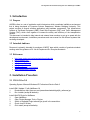
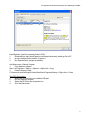
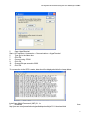
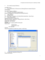
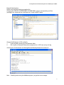
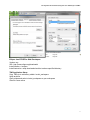
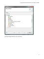
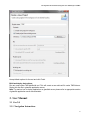
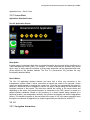
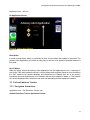
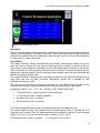
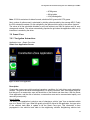
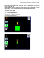
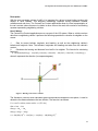
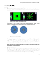
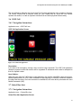
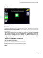
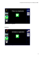
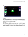
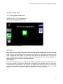
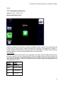
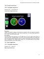
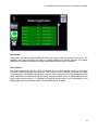
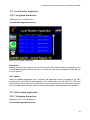
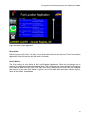
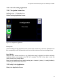
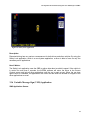
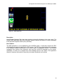
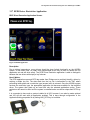
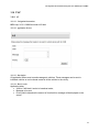
Development Environment Setup and User Manual for AGORA Version 2.0 A Versatile Environment for the Development of IntelliDrive Applications (Visual …Extensible …Rule-Based) Department of Computer Science, Western Michigan University Development Environment Setup and User Manual for AGORA Table of Contents Table of Contents .......................................................................................................................... ii Revision History ............................................................................................................................ ii 1. Introduction ..............................................................................................................................1 1.1 1.2 1.3 Purpose ........................................................................................................................................ 1 Intended Audience ....................................................................................................................... 1 References ................................................................................................................................... 1 2. Installation Procedure .............................................................................................................1 2.1 2.2 VIS/A3/Gov 2.0 ........................................................................................................................... 1 TMC ............................................................................................................................................ 6 3. User Manual .............................................................................................................................9 3.1 3.2 3.3 3.4 3.5 3.6 3.7 3.8 3.9 3.10 3.11 3.12 3.13 3.14 3.15 3.16 3.17 31 3.18 3.19 3.20 3.21 Gov 2.0 ........................................................................................................................................ 9 A3 .............................................................................................................................................. 10 Carbon Emissions Tracker......................................................................................................... 11 Smart Cone ................................................................................................................................ 13 Course/Fine Context .................................................................................................................. 14 VOIP Call .................................................................................................................................. 17 School Bus Alert........................................................................................................................ 17 Police Car/Ambulance/Fire Truck Alert.................................................................................... 18 Tow Truck Alert ........................................................................................................................ 21 Virtual Control Panel ................................................................................................................. 24 Wallet Application..................................................................................................................... 24 Local Weather Application ........................................................................................................ 26 Fuel Location Application ......................................................................................................... 26 Vehicle Tracking Application ................................................................................................... 28 Safety Lock Application ............................................................................................................ 28 Variable Message Sign (VMS) Application .............................................................................. 29 RFID Driver Restriction Application ........................................................................................ 31 TMC .......................................................................................................................................... 32 Tomographic Reports ................................................................................................................ 33 Vehicle Tracker ......................................................................................................................... 35 Vehicle Wallet Viewer .............................................................................................................. 36 Appendix A: Glossary..................................................................................................................37 Revision History Name Date Reason For Changes Version Vinay B Gavirangaswamy 01/24/2010 Initial Draft 1.0 Vinay B Gavirangaswamy 02/16/2010 Changed project name from VII to AGORA, changed paragraph formatting, and reformatted cover page. 1.1 Vinay B Gavirangaswamy 06/22/2010 Enhanced TMC related documentation 1.2 Jamie Lynn Groos 06/23/2010 Enhanced VIS related documentation 1.3 Vinay B Gavirangaswamy 07/06/2010 New version release 2.0 ii Development Environment Setup and User Manual for AGORA 1. Introduction 1.1 Purpose AGORA refers to a set of application and infrastructure which constitutes intellidrive environment that is being developed at Computer Science Department, Western Michigan University. This project consists of several software applications and hardware components. This infrastructure consists of On-Board Equipment (OBE), Road Side Equipment (RSE), and Traffic Management Centers (TMC), which work together to increase the safety and efficiency of the transportation network. This document is intended to help internal and external team member to get up to speed with the development environment, installation procedures and user manual for the different systems that are being developed. 1.2 Intended Audience Document is primarily intended for members of MDOT team which consists of graduate students working under the guidance of Dr. Ala Al-Fuqaha and Dr. Dionysios Kountanis. 1.3 References http://www.oracle.com/us/technologies/java/index.htm http://netbeans.org/ http://www.mysql.com/ http://www.eclipse.org/ http://javafx.com/ http://www8.garmin.com/support https://glassfish.dev.java.net/ 2. Installation Procedure 2.1 VIS/A3/Gov 2.0 Operating System: Microsoft Windows XP Professional Service Pack 3 Install JDK 6 Update 17 with NetBeans 6.8 1. Download from http://java.sun.com/javase/downloads/widget/jdk_netbeans.jsp 2. Run installer (accept all defaults). Install JAVAFX Plugin for NetBeans 1. Open NetBeans. 2. Open Plugins Manager Tools > Plugins 3. Switch to Available Plugin tab and type javafx in the search box. 4. Check JavaFX Kit box. 5. Click Install (accept all defaults). 1 Development Environment Setup and User Manual for AGORA Install Spanner (used for accessing Garmin GPS) 1. Download from http://www8.garmin.com/support/download_details.jsp?id=1627 2. Unzip to desired folder (default: C:\garmin). 3. Run SpannerSetup (accept all defaults). Add Spanner as a Startup Program 1. Copy Spanner program Start > All Programs > Garmin > Spanner > Right-click > Copy 2. Paste to Startup Folder C:\Documents and Settings\All Users\Start Menu\Programs\Startup > Right-click > Paste Test GPS Connectivity 1. Attach the GPS device to an available USB port. 2. Run the Spanner program. 3. Select the GPS from the drop down box. 4. Click the Start button. 2 Development Environment Setup and User Manual for AGORA 5. Open HyperTerminal Start > All Programs > Accessories > Communications > HyperTerminal 6. Type gps in the Name box. 7. Click OK. 8. Connect using: COM1 9. Click OK. 10. Change Bits per second to 9600. 11. Click OK. *If a connection to the GPS is made, data should be displayed similar the image below. Install Java Media Framework (JMF) 2.1.1e 1. Download http://java.sun.com/javase/technologies/desktop/media/jmf/2.1.1/download.html from 3 Development Environment Setup and User Manual for AGORA 2. Run installer (accept all defaults). Add OBDII Library: 1. Copy rxtxSerial.dll to C:\Documents and Settings\Student\.netbeans\6.8\javafxsdk\lib\desktop Setup MDOT Project in NetBeans 1. Copy MDOT files/folders to desired location. (Default: C:\Documents and Settings\Student\Desktop\Research) 2. Open NetBeans. 3. Add new project. File > Open Project > (browse to mdot folder)/PathAnimationNew > Open Project 4. Create LibraryJAVAFX Expand PathAnimation in Projects Tab Right-Click Libraries > Add Library > Manage Libraries > New Library Library Name: LibraryJAVAFX Library Type: Class Libraries Click OK. Add JAR/Folder > (browse to MDOT directory)/lib Select: jce.jar JFXtras-0.5.jar swing-layout-1.0.3.jar Add JAR/Folder Click OK. Select LibraryJAVAFX from Add Library window > Add Library 5. Change path in Application Settings File. Click on the Files tab. 4 Development Environment Setup and User Manual for AGORA Expand PathAnimation. Double click ApplicationSettings.properties file. Change path of RULES, SUPERNODES, ROADSIGNS to point to corresponding xml files. (example2.xml, supernode.xml, xmlOutput.xml - found in MDOT folder) Change Path/Settings in VOIP config file: 1. Create a folder named log in the Research folder. 2. Edit .cfg file (in Research folder) that corresponds to a VOIP user (a.cfg or b.cfg) contacts_file="C:\Documents and Settings\Student\Desktop\Research\contacts.lst" Note: If building and running the NetBeans project, you get the error message: 5 Development Environment Setup and User Manual for AGORA Unable to start java.exe: The system cannot find the file specified. Java did not get installed on the system (even though it should be in the NetBeans bundle). Download and install Java 6 Update 18 from http://www.java.com/en/download/manual.jsp 2.2 TMC Download and install Glassfish Version: 2.1.1 URL: https://glassfish.dev.java.net/public/downloadsindex.html Install location: c:\glassfish Install instruction: Please refer to glassfish web site for install instructions Environment variables: Please setup following system environment variable as shown below Variable Name AS_ADMIN_USER AS_HOME JAVA_HOME Value admin C:\glassfish <your system java install directory> 6 Development Environment Setup and User Manual for AGORA Eclipse Java EE IDE for Web Developers Version: any URL: http://www.eclipse.org/downloads/ Install location: c:\eclipse Install instruction: unzip downloaded archive to above specified directory TMC Application Setup: Copy TMC.zip to a directory called c:\mdot_workspace Upzip archieve Open eclipse and select c:\mdot_workspace as your workspace Goto file->new->other 7 Development Environment Setup and User Manual for AGORA And enter following information in the next screen 8 Development Environment Setup and User Manual for AGORA Accept default options for the rest and click Finish. Build and deploy Instructions: Run ant script under TMC\build\build.xml. This will create a war archived file under TMC\bin\war. Deploy this war file in glassfish application server. Note: To read on how to deploy application on glassfish server please refer to appropriate section of glassfish application sever documentation. 3. User Manual 3.1 Gov 2.0 3.1.1 Navigation Instructions 9 Development Environment Setup and User Manual for AGORA Application Icon →Gov 2.0 Icon 3.1.2 Screen Shots Application Selection Screen: Gov 2.0 Application Screen: Figure 1: Gov 2.0 Description: In some cases it is necessary for a diver to provide information about current driving conditions to a Traffic Management Center (TMC). For example, if a driver encounters an accident, they should have a way to easily report the accident so that proper authorities can be dispatched and other drivers alerted of the possible hazards. The Gov 2.0 (Government 2.0) provides the very functionality described above. How It Works: The Gov 2.0 application displays hazards (as icons) that a driver may encounter in the transportation system. When a driver encounters a hazard that needs to be reported, he/she selects the proper hazard by touching the correct icon. Once the icon representing the hazard is selected, a verification area is displayed to confirm the type of hazard along with the latitude and longitude locations of the hazard. The driver then selects the confirm or the cancel button and depending on the action, the hazard information is transmitted to the TMC, where it is stored in a hazard locations database. Based on the frequency of a certain hazard being reported (at a particular location), the transportation authority can prioritize the hazards and take the appropriate actions. This hazard information is also conveyed to the users of VIS in the same geographic area through the on-demand A3 application (or dynamic signs/alerts) as described in section 3.2. 3.2 A3 3.2.1 Navigation Instructions 10 Development Environment Setup and User Manual for AGORA Application Icon →A3 Icon A3 Application Screen: Figure 2: A3 Description: In order to keep drivers safe it is necessary for them to know about the hazards in their area. The Advisory Alert Application (A3) offers an easy way for drivers to be alerted of possible hazards in their area. How It Works: When the driver selects the Advisory Alert application from the applications menu, a message is sent to the TMC that includes the driver‟s current latitude and longitude. Based on this information the TMC searches its hazards database and determines the hazards that are in the driver‟s immediate area and sends back a list of hazards that the driver should be aware of. The hazards are visually displayed with a small icon and some corresponding text that explains the details. 3.3 Carbon Emissions Tracker 3.3.1 Navigation Instructions Application Icon →Car Emissions Tracker Icon Carbon Emissions Tracker Application Screen: 11 Development Environment Setup and User Manual for AGORA Figure 3: Carbon Emissions Tracker Description: With the increasing threat of global warming, individuals are becoming more conscious about their impact on the environment. The Carbon Emissions Tracker allows individuals to track the amount of carbon their vehicle puts into the atmosphere each time they turn the car on by simply displaying it on the screen in a trip-by-trip format. How It Works: The Carbon Emissions Tracker calculates the miles traveled, fuel used and carbon foot print for each “trip” which is defined to be the time from which the engine is started, to the time it shut off. The number of miles traveled is calculated using the GPS device which is attached to the system. Every 10 seconds, the GPS is polled for the new location of the car. The distance between the new latitude and longitude location and the old latitude and longitude location is then calculated and added to the running distance total. The Carbon Emissions Tracker is able to calculate the amount of fuel consumed during a trip by using data read from the OBD (On-Board Diagnostics) System that is standard on cars manufactured starting in 1996. The values of mass air flow and speed are requested from the OBD and then plugged into the following equation which returns the instantaneous miles per gallon (MPG) of the vehicle. Instantaneous MPG = (14.7 * 6.17 * 454 * SPEED) / (3600 * MASS AIR FLOW) 14.7 grams of air to 1 gram of gasoline - ideal air/fuel ratio 6.17 pounds per gallon - density of gasoline 454 grams per pound - conversion 3600 seconds per hour conversion To find the average MPG during a trip, the instantaneous rate is averaged over time. The carbon footprint during a trip requires a few calculated values. First, to calculate the CO2 emissions from a gallon of fuel, the carbon emissions are multiplied by the ratio of the molecular weight of CO2 (m.w. 44) to the molecular weight of carbon (m.w.12): 44/12. CO2 emissions from a gallon of gasoline = 2,421 grams x 0.99 x (44/12) 12 Development Environment Setup and User Manual for AGORA = 8,788 grams = 8.8 kg/gallon = 19.4 pounds/gallon Note: If C02 for emissions for diesel is need, substitute 2421 grams with 2778 grams. Next, number of gallons used is calculated by dividing miles traveled by the average MPG. Finally the C02 emissions constant (19.4)is multiplied by the gallons which results in the carbon footprint. The values of all the calculated variables for a trip are written to an XML file (carbon.xml) for easy storage and retrieval. The values automatically populate the grid when the application starts, so no interaction is needed by the driver. 3.4 Smart Cone 3.4.1 Navigation Instructions Application Icon →Smart Cone Icon Smart Cone Application Screen: Figure 4: Smart Cone Application Description: Construction zones can quickly produce hazardous conditions for both drivers and construction workers. The goal of the Smart Cone application is to quickly create an “alert” area warns the driver that they are in a construction zone and should be on the lookout and slow down. With the Smart Cone application, and the click of a button, a construction zone can be communicated rapidly, and removed just as quickly. How It Works: The Smart Cone application is simply a way of changing a vehicle “type” from a standard vehicle type to a “Smart Cone” type. When the green go button is clicked in the application, the type value in the vehicle's hash table is update to be the Smart Cone type. This information is then propagated in the vehicle's hash table to the neighboring vehicles. Neighboring vehicles look 13 Development Environment Setup and User Manual for AGORA through their context in search of the “Smart Cone”, and if it is found, displays the construction cone icon in their alert area. Similarly, when the application's stop button is clicked, the vehicle type is changed back to that of a standard vehicle, and the propagation process through the hash table is again followed. 3.5 Course/Fine Context 3.5.1 Navigation Instructions Application Icon →Course/Fine Context Icon Course/Fine Application Screen: Figure 5: Course Context Application Figure 6: Fine Context Application 14 Development Environment Setup and User Manual for AGORA Description: With the ever increasing volume of traffic, it is important for a driver to know his/her location with respect to other vehicles. This becomes increasingly important during hazardous weather conditions and rush hour. The Course/Fine Context applications allow for visual representation of the car's context; where there are in relation to other cars on the road; with a series of red flashing squares representing neighboring vehicles. How It Works: The Course/Fine Context applications are a core part of the VIS system. When a vehicle receives data from a neighboring vehicle it performs the following operations to visualize its neighbor on the screen: 1. Gets its current latitude, longitude, and heading, as well as the neighboring vehicle‟s latitude and longitude. Note: The latitudes, longitudes and heading are taken from the vehicle‟s context. 2. Calculates the bearing and distance from itself to its neighbor. The formula for calculating bearing is: 𝜃 = 𝑎𝑡𝑎𝑛2 sin ∆𝑙𝑜𝑛𝑔 ∗ cos 𝑙𝑎𝑡2 , cos 𝑙𝑎𝑡1 ∗ sin 𝑙𝑎𝑡2 − sin 𝑙𝑎𝑡1 ∗ cos 𝑙𝑎𝑡2 ∗ cos ∆𝑙𝑜𝑛𝑔 where 𝜃 represents the direction (in compass degrees). Figure 7: Bearing between two vehicles. The „Haversine‟ formula, which calculates great-circle distances between the two points, is used to determine the distance between the two vehicles. The formula is as follows: 𝑅 = 𝑒𝑎𝑟𝑡ℎ′ 𝑠 𝑟𝑎𝑑𝑖𝑢𝑠 𝑚𝑒𝑎𝑛 𝑟𝑎𝑑𝑖𝑢𝑠 = 6,371 𝑘𝑚 ∆𝑙𝑎𝑡 = 𝑙𝑎𝑡2 − 𝑙𝑎𝑡1 ∆𝑙𝑜𝑛𝑔 = 𝑙𝑎𝑡2 − 𝑙𝑎𝑡1 ∆𝑙𝑜𝑛𝑔 = 𝑙𝑜𝑛𝑔2 − 𝑙𝑜𝑛𝑔1 𝑎 = sin ∆𝑙𝑎𝑡 2 2 + cos 𝑙𝑎𝑡1 ∗ cos 𝑙𝑎𝑡2 ∗ sin ∆𝑙𝑜𝑛𝑔 2 2 15 Development Environment Setup and User Manual for AGORA 𝑐 = 2 ∗ 𝑎𝑡𝑎𝑛2 𝑎, 1−𝑎 𝑑 =𝑅∗𝑐 3. Determine which location on the screen should blink. The Course Context screen has 8 possible locations and the Fine Context has 24 locations as seen below: Figure 8: Course and fine context blinking locations. Each location is given a number as seen below corresponding to the square blinking locations on the screen and it is assumed that the local vehicle is heading north. Figure 9: Vehicle rotation example. If the local vehicle is indeed heading north, then a car directly in front of it (bearing in the range 337.5 to 22.5 on a compass) would be in position 1 and square 1 should blink. However, if the local vehicle was instead heading southeast (as seen in Fig. 9) and a vehicle was directly in front of it, position 4 should blink on the screen. Note: The square that should blink depends on the heading of the local vehicle, NOT the heading of the neighboring vehicles. 4. Blink the selected square. Once the proper square is selected, the location to blink is stored in the local hash table of that neighboring vehicle. Every 500ms, the GUI thread checks all the vehicles in the local hash context for this location information. It then generates a list of squares that should be turned green, and proceeds to do so. The same process repeats indefinitely. 16 Development Environment Setup and User Manual for AGORA The only difference between the Course and Fine Context applications is the number of squares. The Course Context has 8 locations, while the Fine Context has 48. Since the Fine Context squares are smaller, it is able to represent vehicles that are farther physical distance away. 3.6 VOIP Call 3.6.1 Navigation Instructions Application Icon →VOIP Call Icon VOIP Call Application Screen: Figure 10: VOIP Call Application Description: In the case of an emergency, having a way to call for help is essential. The VOIP Call application allows the system to send and receive calls to registered IP addresses which could for example be that of a dispatch center. How It Works: When the user clicks the "call" button on the application, the system uses MjSip (open source javabased implementation of a SIP stack available at www.mjsip.org) to initiate a connection between the caller and the callee. Once the connection is established, the voice data is processed with Java Media Framework (JMF). 3.7 School Bus Alert 3.7.1 Navigation Instructions Application Icon → School Bus Icon School Bus Alert Application Screen: 17 Development Environment Setup and User Manual for AGORA School Bus: Figure 11: School Bus Application Description: School buses make frequent stops to pick up and drop off children. The purpose of the School Bus Alert application is to make drivers aware that there is a school bus in their area and remind them to watch out for children crossing the road. How It Works: The School Bus Alert application is very similar to the Smart Cone Application in that when the green go button is pushed, the vehicle type is changed from a standard vehicle to a school bus. This information is propagated to the vehicle's neighbors. The vehicle type remains “school bus” until the stop button on the application is pressed. When the application is running, neighbors will see a vehicle of type school bus in their context and display a school bus icon in the alert area. 3.8 Police Car/Ambulance/Fire Truck Alert 3.8.1 Navigation Instructions Application Icon →Police Car/Ambulance/Fire Truck Alert Icon Police Car/Ambulance/Fire Truck Alert Application Screen: Police: 18 Development Environment Setup and User Manual for AGORA Figure 12: Police Car Application Ambulance: Figure 13: Ambulance Application 19 Development Environment Setup and User Manual for AGORA Fire: Figure 14: Fire Truck Application Description: When there is an accident, fire, or any other event that requires emergency personnel, response time is critical as seconds can save lives. The purpose of the Police Car, Ambulance, and Fire Truck Alert applications is to alert the driver that one of these vehicles is approaching and proper protocol should be followed as is the law of the state. In Michigan for example, the driver should slow down, pull over and stop while these vehicles pass. How It Works: The Police Car/Ambulance/Fire Truck Alert applications are very similar to the Smart Cone and School Bus Applications in that when the green go button is pushed, the vehicle type is changed from a standard vehicle to a police car, ambulance or fire truck. This information is propagated to the vehicle's neighbors. The vehicle type remains the specified type until the stop button on the application is pressed. When the application is running, neighbors will see a vehicle of type police car, ambulance or fire truck in their context and display the associated icon in the alert area. 20 Development Environment Setup and User Manual for AGORA 3.9 Tow Truck Alert 3.9.1 Navigation Instructions Application Icon → Tow Truck Alert Icon Tow Truck Alert Application Screen: Figure 15: Tow Truck Application Description: When a Tow Truck is called to the scene of an accident or other related event, it is often the case that a partial lane blockage will follow while the truck maneuvers the disabled vehicle into proper position. These lane blockages can be hazardous to other drivers, especially during times of high traffic or sharp and windy roads. The sooner that other driver can know about the Tow Truck, the more time they have to react and reduce speed or change lanes. The Tow Truck application is used to alert drivers to the above mentioned situations. How It Works: The Tow Truck application is very similar to the Police Car/Ambulance/Fire Truck Alert in that when the green go button is pushed, the vehicle type is changed from a standard vehicle to a tow truck. This information is propagated to the vehicle's. The vehicle type remains “tow truck” until the stop button on the application is pressed. When the application is running, neighbors will see a vehicle of type tow truck in their context and display the associated icon in the alert area. 21 Development Environment Setup and User Manual for AGORA Sphinx 3.9.2 Navigation Instructions Application Icon → Sphinx Icon Sphinx Application Screen: Description: Hands free operation is critical when it comes to software running in vehicles. The fewer things that a driver has to control create a safer environment for everyone. The integration of Sphinx, a speech recognizer developed by the Sphinx group at Carnegie Mellon University, allows the driver to switch between screens using simple single word voice commands. How It Works: When the user clicks the start button on the application, the system activates Sphinx4 and waits for the user to speak one of the recognized words. When the system hears a word that it knows, the main screen is changed to screen associated with that word. Sphinx continues to operate until the user clicks the stop button. Currently, the system uses the following words to change between the main application screens: Words Screen application Application course Course Context fine Fine Context call VOIP Call 22 Development Environment Setup and User Manual for AGORA voice Sphinx 23 Development Environment Setup and User Manual for AGORA 3.10 Virtual Control Panel 3.10.1 Navigation Instructions Application Icon → Control Panel Icon Control Panel Application Screen: Figure 17: Virtual Control Panel Application Description: Gauges are essential in vehicles today because the supply the driver with important information such as speed and engine RPMs. In the case the gauge failure, the Control Panel application is able to step in as a backup gauge system. How It Works: The Virtual Control Panel application uses the OBD system of the car to obtain engine RPM and vehicle speed data. The obtained data is then used to move the gauge needles to the appropriate spot on the gauge and also displays the data in a textbox on the gauge for easy viewing. Not only does this application offer a backup gauge system, but it also demonstrates how the AGORA system pulls data from the car OBD computer. 3.11 Wallet Application 3.11.1 Navigation Instructions Application Icon → Wallet Icon Wallet Application Screen: 24 Development Environment Setup and User Manual for AGORA Figure 18: Wallet Application Description: Today there are many scenarios where a driver may need to pay for services during a trip. For example, they may encounter toll roads or parking garages that require payment. The Wallet Application is used to automatically charge a credit card for these types of services. How It Works: The Wallet Application uses the GPS coordinates of a car and compares them to the known locations of parking garages, toll roads, etc. The locations of these entities are stores in an XML file generated by the external Charge Point Capture Utility. Along with the GPS coordinates of the entity, additional information such as the charge amount is stored. When a vehicle passes one of these stored location points it is charged the specified amount and a row is generated on the Wallet Application screen with the date, price and description of charge. 25 Development Environment Setup and User Manual for AGORA 3.12 Local Weather Application 3.12.1 Navigation Instructions Application Icon → Weather Icon Local Weather Application Screen: Figure 19: Local Weather Application Description: Weather can often cause problems for drivers, especially when severe storms are threatening. The Local Weather application allows the driver to access the local five day weather forecast with the touch of a button. How It Works: When the Weather Application icon is selected, the application sends a message to the TMC containing the current latitude and longitude of the vehicle taken from the GPS. The TMC then uses a web service to return the five day forecast to the vehicle. Each day of the forecast is given a row of the table with the column values of date, low temperature, high temperature and summary. 3.13 Fuel Location Application 3.13.1 Navigation Instructions Application Icon → Fuel Gauge Icon Fuel Location Application Screen: 26 Development Environment Setup and User Manual for AGORA Figure 20: Fuel Location Application Description: With fuel prices on the rise, it is often nice to know where the fuel can be found. The Fuel Location application offers this service with the touch of a button. How It Works: The Fuel location is very similar to the Local Weather Application. When the fuel gauge icon is selected, the application sends a message to the TMC containing the current latitude and longitude of the vehicle taken from the GPS. The TMC then uses a web service to return the five cheapest gas stations in the area. Each station is given a row of the table with the column values of price, name of the station, and address. 27 Development Environment Setup and User Manual for AGORA 3.14 Vehicle Tracking Application 3.14.1 Navigation Instructions Application Icon → Configuration Icon VehicleTracking Application Screen: Figure 21: Configuration Application Description: Vehicle tracking can help people be aware of where their vehicles are at all times. Applications like this are especially useful for parents who wish to track the locations of their new teenage drivers. How It Works: When the Track Vehicle check box on the Configuration page is checked, the vehicle continually sends its latitude and longitude to the TMC in a message. The TMC is then able to track the vehicle visually using Google Maps. Note: As some people may see vehicle tracking as an invasion of privacy, it is easily disable by unchecking the Track Vehicle check box. 3.15 Safety Lock Application Safety Lock Application Screen: 28 Development Environment Setup and User Manual for AGORA Figure 22: Safety Lock Application Description: Distracted driving has very serious consequences for both drivers and other vehicles. By using the Safety Lock application, which is a core system application, a driver is able to focus on only the necessary set of applications. How It Works: The Safety Lock application uses the OBD to gather data about a vehicle‟s speed. If the vehicle is in motion for more than 5 seconds, the AGORA software will return the driver to the Course Context screen and lock all other applications until the car is again at rest. When the car does again return to a standstill, the applications will unlock and the driver will be able to navigate to the other applications as usual. 3.16 Variable Message Sign (VMS) Application VMS Application Screen: 29 Development Environment Setup and User Manual for AGORA Figure 23: VMS Application Description: Large Variable Message Signs have been showing up along the highways in the recent years. The AGORA VMS application brings the messages inside the vehicle and allows for custom messages to be delivered to specific areas quickly and easily. How It Works: The VMS application is a core application of the AGORA system. It continually contacts the TMC with latitude and longitude data from the GPS system. The TMC then determines which messages in its database should be delivered to the vehicle based on geographic location. The returned messages have priorities that determine how long they should be displayed on the screen. Additionally, an audio cue is played when new messages arrive at the vehicle. This application allows for important information to be quickly and easily distributed to all vehicles. 30 Development Environment Setup and User Manual for AGORA 3.17 RFID Driver Restriction Application RDIF Driver Restrction Application Screen: Figure 24: RFID Application Description: Due to driving inexperience, young drivers should be given limited functionality on the AGORA system. At the same time, an older more experienced driver may be able to handle the full application set and still drive safely. The RFID Driver Restriction application is able to distinguish between the two drivers with simply a key fob scan. How It Works: The RFID application uses and RFID tag reader from Phidge.com to positively identify a driver by swiping a simple key fob. The data read from the key fob is transmitted to the TMC where processing takes place and a restriction type (access level) is returned. Once the AGORA system receives the restriction type, the appropriate application set becomes available for the identified driver. The system then starts up as usual with only the selected applications active. These restrictions will remain in effect until the system is restarted and a new driver swipes their RFID key fob. It is convenient to have such a system installed in all VIS; however it can also be made optional and VIS will still work with all application enabled. This is done through configuration in the ApplicationSetting.properties file by setting HAS_RFID key to true\false. 31 Development Environment Setup and User Manual for AGORA 3.18 TMC 3.18.1 A3 3.18.1.1 Navigation Instructions URL: http://10.2.2.3:8080/tmc-web-ui/A3.html 3.18.1.2 Application Screen: 3.18.1.3 Description A3 application allows user to send messages to vehicles. These messages can be sent to individual vehicles or can be broad casted to all the vehicles in the vicinity. 3.18.1.4 How it works Application takes VIN# or if left blank it works in broadcast mode, Message to be sent Priority which determine the amount of time that this message will be displayed on the screen 32 Development Environment Setup and User Manual for AGORA 3.19 Tomographic Reports 3.19.1 Navigation Instructions URL: http://10.2.2.3:8080/tmc-web-ui/TomographicReports.html 3.19.2 Application Screen: 3.19.3 Description Tomographic reports are generated for the hazards that are around given geographic area. Report generator takes the visible section on the screen and generates the report for either all the hazards or individual hazards. 3.19.4 How it works In the Hazards menu user can either select one among following options Ice condition Pot holes Road kill Foggy Animal 33 Development Environment Setup and User Manual for AGORA Accident 34 Development Environment Setup and User Manual for AGORA 3.20 Vehicle Tracker 3.20.1 Navigation Instructions URL: http://10.2.2.3:8080/tmc-web-ui/VehicleTracker.html 3.20.2 Application Screen: 3.20.3 Description Vehicle tracker application tracks the movement of a given vehicle. 3.20.4 How it works Enter the vehicle‟s VIN# and select the menu option to track vehicle‟s movement. 35 Development Environment Setup and User Manual for AGORA 3.21 Vehicle Wallet Viewer 3.21.1 Navigation Instructions URL: http://localhost:8080/tmc-web-ui/VehicleWalletViewer.html 3.21.2 Application Screen: 3.21.3 Description Vehicle wallet report is summary\history report for all the toll charges. 3.21.4 How it works Enter VIN# for the vehicle, whose toll history should be generated. 36 Development Environment Setup and User Manual for AGORA Appendix A: Glossary MDOT – Michigan Department of Transportation OBE – On-Board Equipment RSE – Road-Side Equipment TMC – Traffic Management Centers A3– Advisory Alert Application LSA – Life Safety Application VIS – Vehicle Integrated Software OSIL- Operating System Isolation Layer OS- Operation System CAL- Communication Abstraction Layer DSRC- Dedicated short range communications 37