1
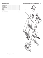
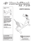
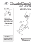
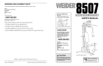
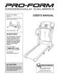
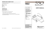
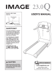
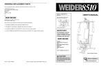
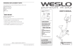
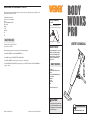
ORDERING REPLACEMENT PARTS
If you encounter any problems with this product, or if you need to order replacement parts, contact the ICON
Health & Fitness, Ltd. office, or write:
ICON Health & Fitness, Ltd.
Customer Service Department
Unit 4
Revie Road Industrial Estate
Revie Road
Beeston
Leeds
LS11 8JG
UK
Model No. WEFMBE14010
Serial No.
Write the serial number in the
space above for future reference.
Tel:
08457 089 009
Serial Number Decal
Outside the UK: 0 (044) 113 387 7133
Fax: 0 (044) 113 387 7125
USER’S MANUAL
QUESTIONS?
When ordering parts, please be prepared to give the following information:
As a manufacturer, we are committed to providing complete
customer satisfaction. If you
have questions, or if there are
missing or damaged parts,
please call:
• the MODEL NUMBER of the product (WEFMBE14010)
• the NAME of the product (WEIDER® BODY WORKS PRO)
• the SERIAL NUMBER of the product (see the front cover of this manual)
• the KEY NUMBER and DESCRIPTION of the part(s) (see the PART LIST and the EXPLODED DRAWING on
pages 10 and 11)
08457 089 009
Or write:
ICON Health & Fitness, Ltd.
Unit 4
Revie Road Industrial Estate
Revie Road
Beeston
Leeds
LS11 8JG
UK
[email protected]
CAUTION
Read all precautions and instructions in this manual before using
this equipment. Save this manual
for future reference.
Part No. 192831 R0605A
Printed in China © 2004 ICON IP, Inc.
Visit our website at
www.iconeurope.com
EXPLODED DRAWING—Model No. WEFMBE14010
TABLE OF CONTENTS
IMPORTANT PRECAUTIONS . . . . . . . . . . . . . . . . . . . . . . . . . . . . . . . . . . . . . . . . . . . . . . . . . . . . . . . . . . . . . . . . .3
BEFORE YOU BEGIN . . . . . . . . . . . . . . . . . . . . . . . . . . . . . . . . . . . . . . . . . . . . . . . . . . . . . . . . . . . . . . . . . . . . . . .4
PART IDENTIFICATION CHART . . . . . . . . . . . . . . . . . . . . . . . . . . . . . . . . . . . . . . . . . . . . . . . . . . . . . . . . . . . . . . .5
ASSEMBLY . . . . . . . . . . . . . . . . . . . . . . . . . . . . . . . . . . . . . . . . . . . . . . . . . . . . . . . . . . . . . . . . . . . . . . . . . . . . . . .6
ADJUSTMENTS . . . . . . . . . . . . . . . . . . . . . . . . . . . . . . . . . . . . . . . . . . . . . . . . . . . . . . . . . . . . . . . . . . . . . . . . . . .9
PART LIST . . . . . . . . . . . . . . . . . . . . . . . . . . . . . . . . . . . . . . . . . . . . . . . . . . . . . . . . . . . . . . . . . . . . . . . . . . . . . . .10
EXPLODED DRAWING . . . . . . . . . . . . . . . . . . . . . . . . . . . . . . . . . . . . . . . . . . . . . . . . . . . . . . . . . . . . . . . . . . . . .11
ORDERING REPLACEMENT PARTS . . . . . . . . . . . . . . . . . . . . . . . . . . . . . . . . . . . . . . . . . . . . . . . . . .Back Cover
R0604A
30
25
26
29
27
24
33
13
28
18
34
5
45
33
34
16
32
26
41
40
37 14
15
35
37
38 39
21 39
39 38
40
41 23 22
36
20
46
12
2
22 2341
12
39
21
37
38
40
41 23
39
17
39
32
32
8
43
35
10
44
12
3
12
11
7
35
35
19
19
32
47
11
49
35
36
4
11
WIEDER is a registered trademark of ICON IP, Inc.
2
9
10
22
31
48
42
6
37
38 39
21 39
39
11
43
32
40
14
16
32
22 23
1
45
15
25
12
39
21
18 13
11
PART LIST—Model No. WEFMBE14010
Key No.
Qty.
1
2
3
4
5
6
7
8
9
10
11
12
13
14
15
16
17
18
19
20
21
22
23
24
25
26
1
1
1
1
1
1
1
1
1
2
4
10
2
2
2
2
2
2
2
1
4
4
4
1
2
2
Description
Key No.
Qty.
27
28
29
30
31
32
33
34
35
36
37
38
39
40
41
42
43
44
45
46
47
48
49
#
#
#
1
2
2
1
1
7
2
2
8
4
4
6
12
4
4
2
2
1
2
1
1
2
2
1
1
1
Seat
Seat Bracket
Rail
Stabiliser
Upper Bar
Support Leg
Adjustment Foot
Adjustment Leg
Adjustment Bracket
Adjustment Bushing
60mm Round Outer Cap
M8 Nylon Locknut
Foam Pad
25mm x 50mm Inner Cap
Large Pulley
Pulley Housing
Small Pulley
Round End Cap
Bumper
Support Leg Isolator
Wheel
Small Bushing
Large Bushing
Handlebar
Inner Cap
Handgrip
R0604A
Description
Knob
Handle
Clip
Cord
M6 x 138mm Bolt
M10 Nylon Locknut
M10 Nylon Locknut (Bright Zinc)
M10 Washer (Bright Zinc)
M10 Washer
M10 x 25mm Bolt
M6 x 16mm Screw
M8 x 42mm Bolt
M8 Washer
M8 x 32mm Bolt
M8 Large Washer
M10 x 55mm Bolt
M10 x 75mm Bolt
M10 x 90mm Bolt
M10 x 30mm Bolt
M4 x 20mm Self-tapping Screw
M6 Nylon Locknut
M6 x 25mm Screw
Plastic Knob
Videocassette
User’s Manual
Workout Chart
Note: “#” Indicates a non-illustrated part. Specifications are subject to change without notice. See the back cover
for information on ordering replacement parts.
IMPORTANT PRECAUTIONS
WARNING:
To reduce the risk of serious injury, read the following important precautions before using the weight training system.
1. Read all instructions in this manual before
using the weight training system.
12. The weight training system is intended for
home use only. Do not use the weight training system in any commercial, rental, or
institutional setting.
2. It is the responsibility of the owner to ensure
that all users of the weight training system
are adequately informed of all precautions.
13. The decal shown here has been placed on
the weight training system. If the decal is
missing or illegible, call our Customer
Service Department at 08457 089 009 and
order a free replacement decal. Apply the
replacement decal in the location shown.
3. Use the weight training system only as
described in this manual.
4. Use the weight training system only on a
level surface. Cover the floor beneath the
weight training system to protect the floor.
5. Inspect and properly tighten all parts each
time you use the weight training system.
Replace any worn parts immediately.
6. Keep hands and feet away from moving parts.
7. Always tie back long hair to prevent it from
becoming caught.
8. Keep children under 12 years old and pets
away from the weight training system at all
times.
9. The weight training system should not be
used by persons weighing more than 115 kg
(250 lbs).
10. Always wear athletic shoes for foot protection whilst exercising.
11. If you feel pain or dizziness whilst exercising, stop immediately and cool down.
WARNING:
Before beginning this or any exercise program, consult your physician. This
is especially important for persons over the age of 35 or persons with pre-existing health problems.
Read all instructions before using. ICON assumes no responsibility for personal injury or property
damage sustained by or through the use of this product.
10
3
BEFORE YOU BEGIN
ADJUSTMENTS
Thank you for selecting the WEIDER® BODY WORKS
PRO weight training system. The versatile BODY
WORKS PRO is designed to help you develop every
major muscle group of the body. Whether your goal is
a shapely figure, dramatic muscle size and strength, or
a healthier cardiovascular system, the BODY WORKS
PRO weight training system will help you to achieve
the specific results you want.
For your benefit, read this manual carefully before
using the BODY WORKS PRO weight training sys-
tem. If you have additional questions, please call our
Customer Service Department at 08457 089 009. To
help us assist you, please note the product model
number and serial number before calling. The model
number is WEFMBE14010. The serial number can be
found on a decal attached to the weight training system (see the front cover of this manual).
The weight training system is designed to use your own body weight as resistance. The steps below explain
how the weight training system can be adjusted and folded for storage. Refer to the accompanying exercise
guide and videocassette to see the correct form for each exercise.
Before reading further, please review the drawing
below and familiarise yourself with the parts that are
labelled.
ADJUSTING THE INCLINE
Rail
Handgrip
Seat
Inspect and tighten all parts each time you use the weight training system. Replace any worn parts immediately.
The weight training system can be cleaned with a damp cloth and mild, non-abrasive detergent; never use
solvents.
3
The incline of the weight training system can be adjusted to change the resistance level of your workout.
To adjust the incline, lift the Rail (3) until the knob on
the Adjustment Bracket (9) can be pulled from the
adjustment hole in the Adjustment Leg (8). Raise or
lower the Frame to the desired incline and insert the
knob into an adjustment hole in the Adjustment Leg.
Note: Be sure that the knob on the Adjustment
Bracket is fully inserted into an adjustment hole in
the Adjustment Leg.
8
Adjustment
Holes
9
Knob
Support Leg
Handle
Adjustment Foot
Adjustment Leg
Adjustment Bracket
ATTACHING THE HANDLEBAR
24
For some exercises, the Handlebar (24) must be
attached to the weight training system. Slide the
Handlebar into the Upper Bar (5) and secure it with the
Knob (27). Turn the Knob clockwise until it is tight.
27
5
CAUTION: Remove the Handlebar
(24) when performing an exercise that does not
require it.
Stabiliser
SECURING THE CORD
When storing the weight training system, or performing
exercises that do not require the use of the Handles
(not shown), secure the Cord (30) by wrapping it
around the Plastic Knobs (49) on the Stabiliser (4).
49
30
4
4
9
6. Remove the Large Pulley (15) from one of the
Pulley Housings (16).
6
45
PART IDENTIFICATION CHART
32
16
Wrap one end of the Cord (30) around the Large
Pulley (15). Reattach the Large Pulley inside the
Pulley Housing (16) with the M10 x 30mm Bolt (45)
and the M10 Nylon Locknut (32). Note: Do not
overtighten the Bolt; the Pulley should be able
to turn easily.
15
29
45
16
28
This chart is provided to help you identify the small parts used in assembly. The number in parenthesis below
each part refers to the key number of the part, from the PART LIST on page 10. Important: Some parts may
have been pre-assembled for shipping purposes. If you cannot find a part in the parts bags, check to
see if it has been pre-assembled.
32
Repeat this step with the other Pulley Housing (16).
30
29
28
Attach a Handle (28) to each end of the Cord (30)
with the two Clips (29).
M10 x 90mm Bolt (44)
7. Make sure all parts are properly tightened before you use the weight training system. The use of the
remaining parts will be explained in ADJUSTMENTS, on page 9.
M10 Washer (34, 35)
M10 x 75mm Bolt (43)
M6 x 16mm Screw (37)
M10 x 55mm Bolt (42)
M8 Large Washer (41)
M6 x 25mm Screw (48)
M8 x 42mm Bolt (38)
M4 x 20mm Self-tapping Screw (46)
M8 x 32mm Bolt (40)
M8 Washer (39)
M6 Nylon Locknut (47)
M10 Nylon Locknut (32, 33)
8
M10 x 30mm Bolt (45)
M8 Nylon Locknut (12)
M10 x 25mm Bolt (36)
5
M6 x 138mm Bolt (31)
15
3. Note: The following steps require two people.
ASSEMBLY
make sure all parts are oriented as shown in the
drawings.
Make Assembly Easier for Yourself.
Everything in this manual is designed to ensure
that the weight training system can be assembled successfully by anyone. Before beginning
assembly, make sure to read the information
on this page; this brief introduction will save
you much more time than it takes to read it.
• For help identifying small parts, use the PART
IDENTIFICATION CHART on page 5.
The following tools (not included) are required
for assembly:
• Place all parts in a cleared area and remove the
packing materials. Do not dispose of the packing
materials until assembly is completed.
• One standard screwdriver
• Tighten all parts as you assemble them, unless
instructed to do otherwise.
Assembly will be more convenient if you have a
socket set, a set of open-end or closed-end spanners, or a set of ratchet spanners. If further assistance is needed, please call our Customer
Service Department at 08457 089 009.
• One Phillips screwdriver
1. Attach the Stabiliser (4) to the Rail (3) with two M10
x 25mm Bolts (36) and two M10 Washers (35).
3
32
6
43
Note: Do not overtighten the Locknuts (32); the
Adjustment Leg (8) and the Support Leg (6)
must pivot easily.
44
4. Have a second person hold the ends of the Cord
(30) above the Seat (1). See the inset drawing.
Slide the Seat Bracket (2) onto the Rail (3). Be sure
that the Wheels (21) are on top of the Rail and
that the Large Bushings (23) are below the Rail.
• Two adjustable spanners
• As you assemble the weight training system,
Attach the Adjustment Leg (8) to the Rail (3) with an
M10 x 90mm Bolt (44) and an M10 Nylon Locknut
(32).
Attach the Support Leg (6) to the Rail (3) with an
M10 x 75mm Bolt (43) and an M10 Nylon Locknut
(32).
• Assembly requires two people.
Before beginning assembly, carefully read the
following information and instructions:
3
8
4
Decal
1
CAUTION: Be sure the Seat (1)
30
is oriented as shown in the drawing.
1
3
3
35
21
2
21
23
3
23
36
35
4
2. Attach the Adjustment Foot (7) to the Adjustment
Leg (8) with two M10 x 55mm Bolts (42), four M10
Washers (35), and two M10 Nylon Locknuts (32).
5. Attach the Upper Bar (5) to the Rail (3) with two
M10 Washers (35) and two M10 x 25mm Bolts (36).
2
5
5
42
8
35
35
3
7
35
35
32
6
35
35
7
36