1
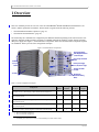
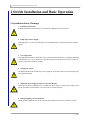
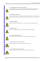
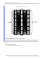
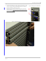
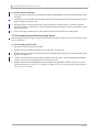
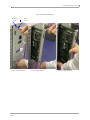
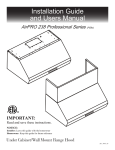
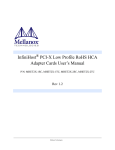
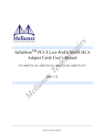
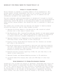
10U 4X SDR/DDR InfiniBand Switch Platform
User’s Manual
Rev 0.60
2
10U 4X SDR/DDR InfiniBand Switch Platform User’s Manual
3
Contents
Contents
3
List of Figures
5
List of Tables
7
About this Manual
9
Chapter 1 Overview
Chapter 2
11
1.1 Ordering Information
1.1.1 Additional Parts for Standalone Ordering
12
12
Switch Installation and Basic Operation
13
2.1 Installation Safety Warnings
2.2 Installation Steps
2.2.1 Physical Installation
2.2.2 Power Connections
2.2.3 InfiniBand Copper Cable Installation
2.2.4 Switch Power Up
2.2.4.1 Power Supply and Spine Board Indicator Status at Power ON
2.2.5 InfiniBand Fabric Initialization and Management
2.2.6 Hot-Swap Extraction/Insertion of Leaf Boards
2.2.6.1 Extracting a Leaf Board
2.2.6.2 Inserting a Leaf Board
2.2.7 Hot-Swap Extraction/Insertion of Spine Boards
2.2.7.1 Extracting a Spine Board
2.2.8 Inserting a Spine Board
2.2.9 Hot-Swap Extraction/Insertion Power Supply Modules
2.2.9.1 Extracting a PSU
2.2.9.2 Inserting a PSU
2.2.10 Hot Swap Replacement of Fan Module
2.2.10.1 Extracting the Fan Module
2.2.10.2 Inserting the Fan Module
2.2.11 Switch Protection Mechanisms
2.2.11.1 Over-temperature Shutdown Mechanism
13
15
15
15
16
17
17
18
19
19
21
21
21
23
24
24
25
26
26
27
28
28
Chapter 3 Switch Management Tools
3.1 IBADM Features
3.1.1 IBADM Requirements
3.1.2 How to Get IBADM
3.2 Embedded Management Tools
Appendix A: Integrated Management Features
A.1 Getting Started: Switch Integrated Management
A.1.1 Serial Console Access
A.1.2 Ethernet Access
A.1.3 Verifying Status of Drivers
31
31
32
32
32
33
33
34
34
35
Appendix B: Specifications
Appendix C: Mechanical Drawings
Appendix D: RS232 Connector Pinout
36
37
38
Revision History
39
Rev 0.60
4
Rev 0.60
10U 4X SDR/DDR InfiniBand Switch Platform User’s Manual
5
List of Figures
Figure 1: Switch Hardware Components
Figure 2: Two Power Inlets - Electric Caution Notification
Figure 3: PSU And Alarm Indicators
Figure 4: Leaf Status, Present, PHY, and Logical Link LEDs
Figure 5: Topology of a 144 4X-Port Switch
Figure 6: Retaining Screw and Red Button
Figure 7: Leaf Board Extraction
Figure 8: Spine Board Extraction
Figure 9: Spine Board Insertion
Figure 10: PSU Extraction
Figure 11: PSU Insertion
Figure 12: Fan Module Extraction
Figure 13: Fan Module Insertion
Figure 14: Default Configuration Model
Figure 15: CPU Status LEDs, Fan Status
Figure 16: Status, Hot Swap, and System Fail LEDs
Figure 17: Chassis Side View Drawing
Figure 18: Chassis Front View Drawing
Figure 19: Chassis Rear View Drawing
Figure 20: Integrated CPU Board Ports Diagram
11
16
17
18
19
20
20
22
24
25
26
27
28
31
33
34
37
37
37
38
Rev 0.60
6
Rev 0.60
10U 4X SDR/DDR InfiniBand Switch Platform User’s Manual
7
List of Tables
Table 1: Reference Documents and Websites
Table 2: Switch Configuration Examples
Table 3: Ordering Part Numbers
Table 4: Additional Part Numbers
Table 5: Switch Rack Mechanical and Environmental Requirements (Fully Populated Chassis)
Table 6: Port LEDs Decoder Table
Table 7: Switch Specifications
Table 8: RJ45 Pinout
Table 9: Revision History of this User’s Manual
9
11
12
12
15
16
36
38
39
8
10U 4X SDR/DDR InfiniBand Switch Platform User’s Manual
9
About this Manual
This manual provides an overview of the 10U Chassis 4X InfiniBand Switch Platform and guidelines for its operation.
Intended Audience
This manual is intended for users and system administrators responsible for installing and setting up the switch platform.
The manual assumes familiarity with the InfiniBand™ architecture specification.
Related Documentation
The documentation set accompanying the 10U 4X InfiniBand Switch platform includes the following:
Table 1 - Reference Documents and Websites
Switch Firmware and Firmware Update Tools
See http://www.mellanox.com under Firmware downloads. Note that the
Switch System described in this manual is based on Mellanox Technologies’ MT47396 InfiniScaleTM III switch device.
InfiniBand Administration (IBADM) Tools User’s Manual
Document no. 2130UM (Mellanox Technologies document)
Describes the installation and use of IBADM tools for management and
firmware updates of platforms based on Mellanox Technologies’ InfiniBand devices.
Available from http://www.mellanox.com under Management Tools.
IB Switch Platforms Embedded Management Tools
Document no. 2141UM
Describes the Embedded Management Tools (EMGT) package, which provides Out-of-Band management capabilities for InfiniBand switches.
Available from http://docs.mellanox.com (requires a Mellanox Technologies customer account).
Rev 0.60
10
Rev 0.60
10U 4X SDR/DDR InfiniBand Switch Platform User’s Manual
11
1 Overview
This User’s Manual provides an overview of the 10U 4X SDR/DDR1 Modular InfiniBand Switch Platform (‘the
Switch’) and the operational environment. The document is organized into the following sections:
• “Switch Installation and Basic Operation” (page 13)
• “Switch Protection Mechanisms” (page 28)
The Switch ships in a minimum base configuration plus additional modules depending on the chosen customer configuration. Optional modules include Leaf boards, a redundant management capability of Spine boards, and redundant power supply units. Figure 1,“Switch Hardware Components” shows the various hardware components required
for installation. Table 2 provides some configuration examples.
Figure 1: Switch Hardware Components
Hot Swap Spine Boards
With Management Interfaces
1 (left) and 2 (right)
Dual AC Imput and ON/OFF
Switch
Leaf Boards
1-12 (Top to
Bottom)
Hot Swap Power Supply
Unit 1 (left) & Unit 2 (right)
Hot Swap Fan Module
Air Intake
Air Exhaust
Mounting Rails
(Rack Front Mounting
Shown)
Table 2 - Switch Configuration Examples
Configuration
Leaf
Boards
Power Supply Spine Board Spine Board
Modules
w/Mgmt
w/o Mgmt
12 4X ports (1 Leaf), 1 Power Supply, 2 Spine boards without management 1
1
1
2
0
12 4X ports (1 Leaf), 1 Power Supply, 1 Spine board w/o management, 1 Spine
board with management
1
1
1
1
144 4X ports (12 Leafs), 1 Power Supply, 1 Spine board w/o management, 1 Spine
board with management
12
1
1
1
144 4X ports (12 Leafs), 2 Power Supplies, 1 Spine board w/o management, 1 Spine
board with management
12
2
1
1
144 4X ports (12 Leafs), 2 Power Supplies, 2 Spine boards with management 2
12
2
0
2
1. This is the minimal configuration.
2. This is the maximal configuration.
1. 4X IB SDR ports transfer data at 10Gb/s, and 4X IB DDR ports transfer data at 20Gb/s.
Rev 0.60
Overview
12
1.1 Ordering Information
Table 3 on page 12 provides an information guide for ordering a specific configuration of the Switch platform.
Table 3 - Ordering Part Numbers
Switch Part Number
Description
TBD
TBD
1.1.1 Additional Parts for Standalone Ordering
Table 4 - Additional Part Numbers
Rev 0.60
Part Number
Part Name
TBD
TBD
10U 4X SDR/DDR InfiniBand Switch Platform User’s Manual
13
2 Switch Installation and Basic Operation
2.1 Installation Safety Warnings
1.
Installation Instructions
Read all installation instructions before connecting the equipment to the power source.
2.
Bodily Injury Due to Weight
This equipment is very heavy and should be carried by four people to avoid back and/or other bodily
injuries.
3.
Over-temperature
This equipment should not be operated in an area with an ambient temperature exceeding the maximum
recommended: 50°C (122°F). Moreover, to guarantee proper air flow, allow at least 8cm (3 inches) of
clearance around the ventilation openings.
4.
Stacking the Chassis
The chassis should not be stacked on any other equipment. If the chassis falls, it can cause bodily injury
and equipment damage.
5.
Redundant Power Supply Connection - Electrical Hazard
This product includes a redundant power or a blank in its place. In case of a blank power supply, do not
operate the product with the blank cover removed or not securely fastened.
6.
During Lightning - Electrical Hazard
During periods of lightning activity, do not work on the equipment or connect or disconnect cables.
Rev 0.60
Switch Installation and Basic Operation
14
7.
Copper InfiniBand Cable Connecting/Disconnecting
Copper InfiniBand cables are heavy and not flexible, as such they should be carefully attached to or
detached from the connectors. Refer to the cable manufacturer for special warnings/instructions.
8.
Rack Mounting and Servicing
When this product is mounted or serviced in a rack, special precautions must be taken to ensure that the
system remains stable. In general you should fill the rack with equipment starting from the bottom to the
top.
9.
Equipment Installation
This equipment should be installed, replaced, or serviced only by trained and qualified personnel.
10. Equipment Disposal
Disposal of this equipment should be in accordance to all national laws and regulations.
11. Local and National Electrical Codes
This equipment should be installed in compliance with local and national electrical codes.
12. Norway Electrical Codes - Electrical Hazard
The switch platform must be connected to an earthed mains socket-outlet.
13. Norway Electrical Codes - Electrical Hazard
In Norway, this system should be connected to the IT power distribution system only.
Rev 0.60
10U 4X SDR/DDR InfiniBand Switch Platform User’s Manual
15
2.2 Installation Steps
Installation and initialization of the Switch is a simple process requiring attention to the normal mechanical, power,
and thermal precautions for rack-mounted equipment. The Switch does not require any programming or configuration to begin operation in an InfiniBand fabric using standard compliant Subnet Management software. The following
steps provide a basic overview of the installation process:
1.
Physical Installation - Section 2.2.1
2.
Power Connections - Section 2.2.2
3.
InfiniBand Copper Cable Installation - Section 2.2.3
4.
Switch Power Up - Section 2.2.4
5.
InfiniBand Fabric Initialization and Management - Section 2.2.5
6.
Hot Swap Extraction/ Insertion of Leaf and Spine Boards - Section 2.2.6
7.
Hot Swap Extraction/ Insertion of Power Modules - Section 2.2.9
8.
Hot Swap Extraction/ Insertion of Fan Module - Section 2.2.10
2.2.1 Physical Installation
Warning: This equipment is very heavy and should be carried by four people to avoid back and/or
other bodily injuries.
The Switch uses 10U of rackspace in a standard 19” rack. As shown in Figure 1,“Switch Hardware Components”, the
Switch ships from the factory with the mounting racks on the front side. In addition to the mounting rails, the Switch
requires support underneath the unit to support the un-mounted side (in this case, the rear side).
Please ensure to choose a rack which is able to support the mechanical and environmental characteristics of a fully
populated Switch Chassis as listed in Table 5, “Switch Rack Mechanical and Environmental Requirements (Fully
Populated Chassis)”.
Table 5 - Switch Rack Mechanical and Environmental Requirements (Fully Populated Chassis)
Rack Height
Rack Width
10U
19” (EIA-310)
Rack
Depth
Weight
Max. Power (144 4X Ports)
Ambient Temp.
23.6”
(600mm)
159 lb
(72.2 kg)
TBD [W] @ 220VAC
Dual 100-240VAC Inputs, 5060Hz, 14.5-5.8A
Max: 55ºC
Min: 0ºC
The rack mounting holes conform to the IEA-310 standard for 19-inch racks. Take precautions to guarantee proper ventilation to ensure air intake at the front of the chassis and exhaust in the rear; this is crucial for maintaining good airflow at ambient temperature. In particular, route cables such that they do
not impede the air exhaust from the chassis.
2.2.2 Power Connections
The Switch includes an integrated hot-swap power supply which supports up to two load-sharing 1000W supply
units. The slots for the two power supply units (PSUs) are on the front panel and labelled as 1-2. Two independent AC
inputs are located above the slots, one for each PSU. This dual AC design enables optional use of separate main and
backup AC feeds. The input voltage is auto-adjusting for 110/220 VAC, 50hz or 60hz power connections. The power
cords should be standard 3-wire AC power cords including a safety ground.
Rev 0.60
Switch Installation and Basic Operation
16
Install at least one power unit to turn on the Switch. A single PSU can supply power for all configurations including
the maximum populated system. The second PSU provides a failover mechanism such that the system will continue
operating when one PSU fails.
Figure 2: Two Power Inlets - Electric Caution Notification
2.2.3 InfiniBand Copper Cable Installation
The Switch uses industry standard 4X InfiniBand copper cables which are available from several vendors. The standard 4X cables support full 20+20Gb/s (DDR) and 10+10Gb/s (SDR) bidirectional wire speed of the Switch ports.
All InfiniBand 4X connections are made to the Leaf Boards. Each Leaf has 12 InfiniBand 4X copper connectors
which are numbered 1-12 from left to right.
All cables can be inserted or removed with the unit powered on. To insert a cable, press the connector onto the port
receptacle until the connector is firmly seated. The green LED indicator to the left of the port will light when the
physical connection is established (when unit is powered on). Then lock the connector using the latching mechanism
particular to the cable vendor. To remove, disengage the lock and slowly pull the connector away from the port receptacle.
Table 6 is a decoder of the ports yellow and green LEDs states.
Table 6 - Port LEDs Decoder Table
Port Green LED State
Port Yellow LED State
ON (steady)
OFF
ON (steady)
ON (Steady)
Blinking
--
ON (Steady)
Blinking
OFF
OFF
Description
Physical link connection of port is established, but the logical link
connection is not
Both the physical and logical link connections of port are established
Physical link error
Transfer activity is on-going. Blinking rate is proportional to traffic
rate
Cable is unseated / unconnected
Note: The switch does not provide a visual means that indicates the port speed configuration (SDR/DDR).
The speed configuration, however, can be retrieved using software.
Rev 0.60
10U 4X SDR/DDR InfiniBand Switch Platform User’s Manual
17
Warning: Take care to not impede the air exhaust flow through the ventilation next to the InfiniBand
ports. Use cable lengths which allow routing horizontally around to the side of the chassis before bending upward or downward in the rack.
2.2.4 Switch Power Up
Check all boards, power supply, and fan tray modules for proper insertion and seating before turning on the power
switch (read Section 2.2.6 through Section 2.2.7 to ensure all modules are properly installed). Do not leave any open
slots in the chassis. Insert thermal blanks in unused leaf slots and make sure that both power supply doors are shut in
order to maintain balanced air flow. Also, mounting screws should all be tightened.
The power switches are located just above the AC inputs as shown in Figure 1, “Switch Hardware Components,” on
page 11.
2.2.4.1 Power Supply and Spine Board Indicator Status at Power ON
As the power is turned on, you should observe the following conditions for normal operation:
1.
Power Supply Unit(s) AC OK and DC OK indicators are ON and Alarm indicator is OFF. See Figure 3.
Figure 3: PSU And Alarm Indicators
2.
All LED indicators on the Spine and Leaf Boards light up briefly and then
turn off.
3.
Spine Board indicators will display status of internal links to the installed
Leaf Boards. All PHY links to present Leaf Boards should be ON.
4.
There is a green Status LED that indicates (per Spine and per Leaf) Board
that all its power supplies are good. Make sure that all are on. (See
Figure 4.)
5.
There is a yellow Status LED per Leaf and per Spine Board. For a Leaf
Board it should always be off. For a Spine Board it is on in case one of its
power supplies are faulty. Make sure they are all off.
6.
For Spine Boards only: There is a yellow System Fail LED that will light to
indicate one of the following failure situations: a fan failure, over-temperature, or a main AC power supply failure. On power-on this LED will blink
for several seconds and then turn off if none of the above situations has
occurred.
7.
There is a blue LED per Spine and per Leaf Board. It should be off for all boards.
Rev 0.60
Switch Installation and Basic Operation
18
The Spine Board has two sets of indicators. One shows
which Leaf Boards are present. The second set shows
the internal link status to the Leaf Boards. The green
PHYSICAL LINK LED indicators on the Spine (and
Leaf) Boards will indicate the state representing the
link status of their corresponding ports. The green PHY
LED is (steady) ON to indicate the physical link is up.
It blinks to indicate a physical link error.The yellow
LOGICAL LINK LED indicates the logical link is
active and will turn ON only when the link is enabled
by subnet management software in the InfiniBand subnet. It blinks during activities, and the blinking rate is
proportional to traffic rate.
Figure 4: Leaf Status, Present, PHY, and Logical Link LEDs
PHY (Green) LEDs
Logical (Yellow) LEDs
2.2.5 InfiniBand Fabric Initialization and Management
Subnet Management and Subnet Administration are standard components defined by the InfiniBand Specification
which implement fabric initialization, discovery, and configuration. The Switch switching fabric can be managed by
any third party Subnet Management software running on an InfiniBand Host that is connected to any Switch port. The
Switch is also compatible with the Open Source Subnet Manager OpenSM.
The Switch is basically an InfiniBand fabric built out of individual InfiniBand switch devices and appears so to external Subnet Managers. The Switch supports the SystemImage GUID feature of the InfiniBand specification which
means that software management tools that support this feature can recognize all the internal devices as a single
Switch system.
Figure 5 shows the topology of a fully populated all-4X ports System (144 ports). The system features up to 2.88
Tbit/sec (IB ports in DDR configuration)1 Constant Bisectional Bandwidth (CBB) Fat Tree topology that the Subnet
Manager will discover and configure to enable a full cluster to operate. For more information refer to the documentation of the Subnet Manager being used.
1. 1.44 Tbit/sec when IB ports are in SDR configuration
Rev 0.60
10U 4X SDR/DDR InfiniBand Switch Platform User’s Manual
19
Figure 5: Topology of a 144 4X-Port Switch
Spine Board
1
Leaf1
Spine1
Leaf7
Leaf3
Spine1
Leaf8
Leaf4
Spine1
Leaf9
6 Leaf Board
6 Leaf Boards
Leaf5
Spine2
Leaf10
Leaf6
Spine2
Leaf11
Leaf2
Spine2
Leaf12
Spine Board
2
2.2.6 Hot-Swap Extraction/Insertion of Leaf Boards
Switch Leafs are located on the back of the system. Each Switch Leaf board has a pair of ejectors that lock the board
in place and serve as a lever for seating or extracting (see Figure 7). The ejectors snap inward to lock the board into
place and include a red button to disengage the lock and electrically notify the system that an extraction has been
requested.
2.2.6.1 Extracting a Leaf Board
1.
Disconnect all cables connected to the Leaf board.
Rev 0.60
Switch Installation and Basic Operation
20
2.
Unscrew the retaining screws on the outside of the connectors. These
screws are captive and will remain hanging in place. See Figure 6.
3.
Press the red buttons to unlock the ejectors.
4.
Press the ejectors outward so that the board pops out, then slowly
slide the board out. Note that the board is short, therefore do not let
go of it while sliding it out. See Figure 7.
Figure 6: Retaining Screw and Red Button
Retaining
Screw
Red
Button
Figure 7: Leaf Board Extraction
Rev 0.60
10U 4X SDR/DDR InfiniBand Switch Platform User’s Manual
21
2.2.6.2 Inserting a Leaf Board
1.
Verify the ejectors are unlocked by pressing the red buttons and pulling the ejectors outward on both sides of the
board slot.
2.
Carefully seat the Leaf board into the side guide rails and slowly slide the board into the chassis until the ejectors
begin to engage on the chassis edge.
3.
Begin pressing the ejectors inward to fully seat the connectors. If unusual resistance is experienced, pull the
board out and inspect for bent pins or connector problems. Otherwise continue to seat the board with the ejectors
until the locks snap.
4.
Screw in the captive retaining screws on the outside of each ejector to lock the Leaf board in place.
2.2.7 Hot-Swap Extraction/Insertion of Spine Boards
Each Switch Spine board has a pair of ejectors that lock the board in place and serve as a lever for seating or extracting (see Figure 8(a)).
2.2.7.1 Extracting a Spine Board
1.
Disconnect all cables connected to the spine.
2.
Unscrew both (top and bottom) retaining screws of the spine. See Figure 8(a).
3.
Hold the spine ejectors and press both of them outward simultaneously. Expect some resistance before the board
pops out. See Figure 8(a).
4.
Pull the ejectors out till they form 90 degrees with the panel of the system. Then slide the Spine board about 4
inches (~10cm) out by slowly pulling the ejectors. See Figure 8(b).
5.
Hold the board with one hand supporting its bottom and the other grasping its middle (see Figure 8(c)). Then
slide the board all the way out. Note not to damage the GBX connectors on the board and/or the EMI gasket of
the spine-hole in the system.
Rev 0.60
Switch Installation and Basic Operation
22
Figure 8: Spine Board Extraction
Retaining
Screw
Spine
Ejector
(a) Step 3 of Spine Extraction
Rev 0.60
(b) Step 4 of Spine Extraction
(c) Step 5 of Spine Extraction
10U 4X SDR/DDR InfiniBand Switch Platform User’s Manual
23
2.2.8 Inserting a Spine Board
Note: Do not insert a Spine board before Leaf boards are inserted. This may damage the chassis.
1.
Hold the Spine board with one hand supporting its bottom and the other grasping its middle (as in Figure 9(c)).
2.
Insert the board into its rail. The board should slide in without resistance.
3.
Once the board is about 4 inches (~10cm) inside its rail, hold the spine ejectors and push the board in until it cannot move.
4.
Make sure the spine ejectors are open all the way (90 degrees). Now press both ejectors inward simultaneously.
You should feel the ejectors are hooked into the front panel. See Figure 9(a).
5.
With the guide pin (at top of the board from inside) aligned with its hole in the system panel, press both ejectors
applying some force to close them completely. The ejectors have small security pins that should fit into the small
slots in the Spine board panel. See Figure 9(b).
Note: Some switch versions have a captive screws instead of a security pin.
6.
Screw in the captive retaining screws to the left of each ejector to lock the Spine board in place.
Rev 0.60
Switch Installation and Basic Operation
24
Figure 9: Spine Board Insertion
Guide Pin
Ejector Hook
Security
Pin
Slot for
Securing
Spine Ejector
(a) Guide Pin
(b) Securing the Spine
board
2.2.9 Hot-Swap Extraction/Insertion Power Supply Modules
A PSU (Power Supply Unit) in a redundant configuration can be extracted without bringing down the system. A single PSU should not be extracted with the system on if the system is not in redundant configuration. Please refer to
Figure 1,“Switch Hardware Components” for location of the PSU components.
2.2.9.1 Extracting a PSU
1.
Turn off the AC switch (see Figure 10(a)). Note that the (yellow) System Fail LED turns on (see Figure 10(b)).
2.
Disconnect the AC cord.
3.
Open the PSU panel door by loosening the retaining screw.
4.
Press the square locking button in the lower left corner of the PSU. The lever on the lower side should pop out.
See Figure 10(c).
5.
Pull the lever outward (to the right) till the PSU unseats. The (yellow) System Fail LED should turn off.
6.
Remove the PSU with one hand pulling the lever and the other supporting the PSU from the bottom (see
Figure 10(d)).
Rev 0.60
10U 4X SDR/DDR InfiniBand Switch Platform User’s Manual
25
Figure 10: PSU Extraction
AC Switch
System Fail
LED
AC Inlet
Retaining
Screw
PSU Panel
Door
(b) Yellow System Fail
LED location
(a) AC Switch, Inlet, Door
Square
Locking
Button
PSU Lever
(c) Press square button to pop out lever (Step 4)
(d) Pulling out the PSU (Step 6)
2.2.9.2 Inserting a PSU
1.
Make sure the AC switch is turned off.
2.
Disconnect the AC cord.
3.
Make sure the lever is unlocked.
4.
Insert by sliding the PSU into the opening until slight resistance is felt. With the lever opened all the way, push
the PSU in until it seats completely. See Figure 11(a).
5.
Press the lever in until it locks. Hold the nearby mounting rail for support. See Figure 11(a).
6.
Close the PSU panel door and tighten the retaining screw.
7.
Connect the AC cord.
8.
Turn the AC switch back on. The (green) AC OK and DC OK LEDs should turn on.
Rev 0.60
Switch Installation and Basic Operation
26
Figure 11: PSU Insertion
(a) With the lever open, push the PSU till it
seats completely (Step 4)
(b) Press the lever in to lock it (Step 5)
2.2.10 Hot Swap Replacement of Fan Module
The fan module of the Switch platform is located in the center of the front panel (see Figure 12(a)). It includes three
fans. The system is designed to shut down in the following two fan-related cases:
• Failure of two out of the three fans for more than 3 minutes
• No fan module is in the system for more than 3 minutes
Note: The yellow Fan Fail LED will blink the moment one fan fails. This is a warning that the fan module
should be replaced soon.
2.2.10.1 Extracting the Fan Module
1.
Unscrew the four captive screws that hold the fan module to the chassis. See Figure 12(a).
2.
Slowly slide out the fan module while holding both its upper and lower ejectors.
3.
Notice that a yellow Fan Fail LED located on the Spine Board is now blinking. See Figure 12(b).
Rev 0.60
10U 4X SDR/DDR InfiniBand Switch Platform User’s Manual
27
Figure 12: Fan Module Extraction
Yellow Fan
Fail LED
Upper
Ejector
Fan Module
Boundaries
Retaining
Screws
(b) Fan Status LEDs
(a) Fan module boundaries
2.2.10.2 Inserting the Fan Module
You now have up to 3 minutes to insert a new fan module (otherwise the system will shut down):
1.
Slowly slide in the new fan module while holding both its upper and lower ejectors. Make sure the guide pin (at
top of the module from inside) is aligned with its hole before pushing the module all the way in. See
Figure 13(b).
2.
Screw back the four captive screws.
3.
Make sure that the yellow Fan Fail LED is turned off and the green Fan Good LED is on. See Figure 12(b).
Figure 13(a) shows the three fans in the extracted module and the opening in the MTS1400 platforms where it should
fit.
Rev 0.60
Switch Installation and Basic Operation
28
Figure 13: Fan Module Insertion
Guide Hole
Guide Pin
(b) Make sure Guide Pin is aligned
with its hole when pushing
(a) Fan module includes three fans
2.2.11 Switch Protection Mechanisms
The Switch design includes protective mechanisms which shutdown the switch system upon detecting one of the following critical conditions:
1.
Fan related conditions: A failure of two out of the three fans for more than 3 minutes, or the lack of a fan module
in the system for more than 3 minutes causes a shutdown of the switch system. See Section 2.2.10 for more
details.
2.
Over-temperature condition: The Switch0 monitors the temperature on the Spine cards of the system. If the temperature exceeds a certain threshold, a thermal shutdown occurs. See Section 2.2.11.1 for details.
2.2.11.1 Over-temperature Shutdown Mechanism
The Switch system uses an on-board thermal sensor to track the Spine cards temperature. If a card’s temperature
exceeds an over-temperature protection threshold, a thermal shutdown occurs.
Over-temperature threshold:
The over-temperature threshold per card is set to 70ºC. This temperature is reached, for example, at 57ºC ambient
temperature with a single fan working.
Shutdown process:
1.
The ‘System Fail’ LED starts to blink.
2.
After 3 minutes the system shuts down:
Rev 0.60
10U 4X SDR/DDR InfiniBand Switch Platform User’s Manual
29
• All Leaf cards power
• Main Spine cards power rails
• Fans power
3.
The ‘System Fail’ LED stops blinking and remains constantly on.
Note: The only power active after the shutdown is the 5V Auxiliary power of the Spine cards.
Recovery process:
If the temperature goes below the threshold within 3 minutes of shutdown initiation, the system aborts the shutdown
process and returns to normal operation. After 3 minutes, the power sources listed above are powered-down. To
restart the system’s operation, the main AC switch must be turned off then on again.
Rev 0.60
Switch Installation and Basic Operation
30
Rev 0.60
10U 4X SDR/DDR InfiniBand Switch Platform User’s Manual
31
3 Switch Management Tools
This chapter describes:
• In-Band management of the Switch System using the IBADM package (Section 3.1)
• Out-of-Band management of the Switch System via Embedded Management Tools (Section 3.2)
3.1 IBADM Features
Maintenance and configuration of the Switch is done in-band through the InfiniBand fabric using the Mellanox
InfiniBand Administration (IBADM) tools package (see “Related Documentation” on page 9). This package provides
the ability to make firmware upgrades and monitor the temperature, voltage, port utilization, and other status parameters in the switch.
The IBADM tools enable the system administrator to manage one or more Switches from a single remote InfiniBand
host. The features include the following:
• Full In-Band Management of multiple Switch Systems and Mellanox HCA Systems from a single host
• Simple default configuration to get started quickly
• Name-based subnet browsing and topology verification
• Event monitoring of port statistics, link status and system status for all ports in the switch
• Checking and updating the firmware
• Intuitive Command Line Interfaces
• Extensible and customizable via common scripting languages
Note: IBADM provides no baseboard management capabilities.
Figure 14 shows the default configuration model for these tools:
Figure 14: Default Configuration Model
Switch Administration Components:
MTS14400 Switch System
•
HCA
•
Driver
•
IBADM Tools
Host
InfiniBand HCA
InfiniBand
Subnet
Manager
Rev 0.60
Switch Management Tools
32
3.1.1 IBADM Requirements
The general requirements for installing the IBADM software are listed below. Please see the IBADM release notes
for details on platform, OS, Driver and Subnet Management support.
1.
Computer Platform with any Mellanox Technologies InfiniHostTM HCA installed
2.
HCA Driver
3.
InfiniBand compliant Subnet Management. The Open source Subnet Manager (OpenSM) is recommended.
3.1.2 How to Get IBADM
The IBADM tool and documentation are available for download via http://www.mellanox.com. See “Related Documentation” on page 9.
3.2 Embedded Management Tools
Embedded Management Tools are based on the I2C interface of the switch system. These tools can be run from the
embedded Power-PC CPU card installed in the switch, or from the Linux host PC via a USB to I2C adapter (an
MTUSB-x device available from Mellanox).
These tools enable basic chassis management functions such as:
• monitoring temperature, voltages, power supplies and fans
• Querying for board serial numbers and their revisions
In addition, the tools enable firmware management capabilities such as:
• Querying for existing firmware versions
• Burning new firmware (from scratch or for recovery from damaged firmware)
• Querying for and changing system GUIDs
• Checking for duplicate or bad GUIDs
For further details, see Embedded Management Tools User’s Manual.
Rev 0.60
10U 4X SDR/DDR InfiniBand Switch Platform User’s Manual
33
Appendix A: Integrated Management Features
The default and recommended way to manage the Switch is using the IBADM package as described in Chapter 3. All
features described below are also available with the IBADM tools. However, the Switch may include an integrated
management CPU (on a Spine board) that provides an alternate method of performing some of the management functions.
The CPU and dedicated control logic is located on the Spine board for monitoring the chassis hardware environment
and hot-swap events. This CPU is accessible through an RS-232 Serial port or an Ethernet 10/100 interface. The following functionality is provided:
• Familiar Linux OS environment with RS-232 Console Interface and Ethernet Secure Shell Access.
Note: Fabric management is defined in Chapter 14, Subnet Management, within the InfiniBand 1.2 Specification. The Switch does not include integrated subnet management. Thus an external host-based Subnet
Manager is required to support the required InfiniBand fabric management functions.
The following section describes how to configure and use the Operating System.
A.1 Getting Started: Switch Integrated Management
Figure 1: CPU Status LEDs, Fan Status
Embedded management is implemented by a processor on one of the
Spine boards. The Spine with an active CPU can be identified by a
lighted “CPU Status” indicator on the Spine I/O panel (see Figure 1).
This requires special SW support on the management board (please
contact Mellanox Technologies).
The I/O panel also has a serial RS-232 console port or Ethernet 10/
100 port to access the CPU. The processor runs a Linux Operating
System tuned for embedded operation and provides a standard environment for remote access.
After a correct power up sequence, both Spine Boards should have
the Status LED ON and Hot Swap and System Fail LEDs OFF (and
at least one spine has the “CPU STATUS” on). See Figure 2.
Note: The CPU Status LEDs and the Ethernet activity LEDs
require CPU SW support. Mellanox Technologies does not
include such support in the supplied management utilities package.
Rev 0.60
34
Figure 2: Status, Hot Swap, and System Fail LEDs
The Switch operating system has the following features:
1.
64MBytes of System Memory
2.
16MB Flash File system including basic Linux tools and secure shell remote access
3.
Pre-installed Switch tool kit for hot-swap management, firmware management, and monitoring.
The Linux kernel will boot automatically when the Switch is powered on. To reboot the OS use the reboot command
at the OS prompt. Boot time is approximately 40 seconds.
All necessary drivers and services for Switch applications are automatically started at boot time.
A.1.1 Serial Console Access
The serial port provides a standard console login to the embedded OS. It is accessible through the RJ45 connector on
the Spine Board Panel (see “RS232 Connector Pinout” on page 38). A standard DB9 to RJ45 serial cable (or equivalent) can be used to connect from a standard PC serial port.
The Switch is shipped with the following default login parameters:
Serial Port Configuration:
Username: root
Password: 1234
9600 Baud rate, 8bits, No Parity, 1 Stop bit
Once logged in, a standard Linux command line is available.
A.1.2 Ethernet Access
Access is also provided through the 10/100 Ethernet Port. By default the interface is configured to use DHCP to
automatically assign an IP address and other network parameters.
If you choose to statically configure the Ethernet interface, you must log in through the serial console and edit the
/etc/sysconfig file to your preferred IP ADDRESS and NETMASK follows:
bash-2.05# vi /etc/sysconfig/network
NETWORKING=yes
DEVICE=eth0
Rev 0.60
10U 4X SDR/DDR InfiniBand Switch Platform User’s Manual
35
BOOTPROTO=none
HOSTNAME=gz1
IPADDR=<Your chosen IP ADDRESS>
NETMASK=<Your chosen NETMASK>
GATEWAY=
NETWORK=
BROADCAST=
Once the ethernet interface is working, remote login is provided via secure shell as shown in the following example:
Remote Host Prompt: ssh <Your Switch IP Address>
username: root
password: 1234
bash-2.05:
A.1.3 Verifying Status of Drivers
The OS booting sequence will also automatically start the necessary drivers and services for the Switch applications.
The tool kit is stored in the flash file system at /usr/mellanox. The following shows how to check the status of the
driver and application services and the correct responses:
bash-2.05# mst status
MST modules:
-----------MST PCI module is not loaded
MST PCI configuration module is not loaded
MST Calibre (I2C) module is not loaded
MST 8xx module loaded
MST devices:
-----------/dev/mst/mif-i2c-8xx:
- MPC860 Motorola I2C master
The root filesystem is configured as a ram disk, which means any changes made to the user environment will not persist across a reboot or power cycle.
Rev 0.60
36
Appendix B: Specifications
Table 1 - Switch Specifications
Physical
Power and Environmental
Size:
Weight:
Mounting:
Air Flow:
Heat Dissipation:
20Gb/s Connector1:
17.5” (10U) H x 23.6” D x 19” W
159 lb (72.2 Kg) fully configured
19” Rackmount
600CFM (200CFM each fan)
1000W
InfiniBand
Protocol Support
Auto-Negotiation 20 (4X DDR), 10 (4X
SDR), 5 (1X DDR), 2.5 (1X SDR)
QoS: 8 InfiniBand Virtual Lanes for all ports
RDMA Support:
Yes, All Ports
Management: Baseboard, Performance, and Device management Agents for full InfiniBand InBand Management
Supports SystemImage GUID
Scalability and Performance
Addressing:
Hot Swappable:
Simultaneous wire-speed any port to any
port
48K Unicast Addresses Max. per Subnet
16K Multicast Addresses per Subnet
4X Leaf Boards 12 10or 20 Gb/s Ports
1. The connector is good for 10Gb/s operation too.
Rev 0.60
100-240VAC 50-60Hz 14.5-5.8A
TBD [W] @ 220VAC
0 to 55º Celsius
10% - 90% non-condensing
-48VDC
Regulatory
InfiniBand:
Switching Performance:
Voltage:
Maximum Power:
Temperature:
Humidity:
Altitude:
Shock:
Vibration:
Internal Voltage:
Safety:
TBD
EMC:
TBD
Reliability, Availability and Serviceability Features
Code Load and Activation:
Hot Swappable:
N+1 Redundant:
Link Failover:
Fan Module, Power Supplies, Leaf and
Spine Modules
Power Supplies and Fans
Yes: IB Automatic Path Migration
10U 4X SDR/DDR InfiniBand Switch Platform User’s Manual
37
Appendix C: Mechanical Drawings
Figure 3: Chassis Side View Drawing
Figure 4: Chassis Front View Drawing
Figure 5: Chassis Rear View Drawing
Rev 0.60
38
Appendix D: RS232 Connector Pinout
The RS232 monitor connector is a shielded RJ45 Jack, where the shield is connected to GND. The jack pinout is provided in Table 2. In Figure 6,“Integrated CPU Board Ports Diagram”, the jack is module instance ‘PM1’.
Table 2 - RJ45 Pinout
Pin Number
Pin Name
1
NC
2
NC
3
DTR#
4
GND
5
RXD
6
TXD
7
CTS#
8
RTS#
Figure 6: Integrated CPU Board Ports Diagram
Rev 0.60
10U 4X SDR/DDR InfiniBand Switch Platform User’s Manual
39
Revision History
Table 3 - Revision History of this User’s Manual
Revision
Date
0.60
Oct 2006
Details
No 12X port Leafs are available. All 12X relevant text is removed.
Added Section 2.1, “Installation Safety Warnings,” on page 13
Added a note to Section A.1, “Getting Started: Switch Integrated Management,” on
page 33 regarding SW support for CPU Status and Ethernet activity LEDs
Minor text modifications (to enhance clarity) throughout the document
0.50
Dec 2005
Added a description of Out-of-Band, Embedded Management Tools as “Embedded Management Tools” on page 32. The tools’ User’s Manual is listed in under “About this Manual” on page 9
0.40
Nov 2005 First revision released
Rev 0.60
40
Rev 0.60