1
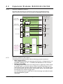
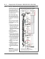
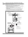
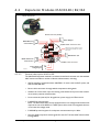
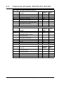
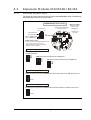
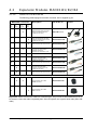
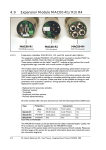
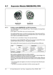
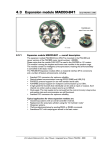
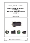
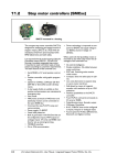
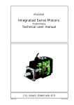
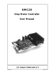
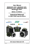
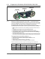
4.2
Expansion Modules MAC00-B1/B2/B4
MAC00-B4
With M12 connectors
MAC00-B2
With cable glands
MAC00-B1
With DSUB connectors
4.2.1
Expansion modules MAC00-B1, B2 and B4 — overall description
The expansion modules MAC00-B1, B2 and B4 can be mounted in all the standard MAC
motors up to MAC800. These modules are among the simplest and lowest cost modules
in the product range. The modules contain no intelligence (microprocessor).
The MAC00-B1, B2 or B4 expansion module offers an industrial interface that mates with
the standard MAC motor and offers a number of feature enhancements, including:
• Different kinds of connectors for more reliability (compared to the basic motor itself).
• Full RS232 protocol support for use with standard serial cable.
• Full RS485 protocol support for multipoint communication up to 100m.
• Sourcing (PNP) outputs for status signals O1 and O2 instead of sinking (NPN).
• Only MAC00-B1: LEDs to indicate: O1, O2 output status. Zero switch (analogue input) status and Input power status.
• Only MAC00-B2 and B4: Dual supply. The main supply can be removed but the control circuitry is kept active and position data and communication are still functional.
Typical applications for these expansion modules are:
• Closed loop systems with an overall controller involved.
• Replacement for pneumatic cylinders using the “Air Cylinder mode”
• Dispenser systems
• Simple velocity or torque control via +/-10V input.
• Machine adjustment/setup by sending RS232 or RS485 commands.
The B1, B2 and B4 are equivalent except for the following hardware differences:
Type
Protection
Class
Connectors
Dual
Supply
I/O and interface
Power supply
LEDs at I/O
MAC00-B1
IP42
DSUB 9 pole
3 pole Phoenix
Yes
No
MAC00-B2
IP67/IP65*
Cable glands
Cable glands
No
Yes
M12
M12
No
Yes
IP67/IP65*
MAC00-B4
Note*: IP65 on MAC400-800
JVL Industri Elektronik A/S - User Manual - Integrated Servo Motors MAC050 - 800
79
4.2
Expansion Modules MAC00-B1/B2/B4
4.2.2
General hardware aspects
All internal and external main connections can be seen in the illustration below.
Please note that a few features are only available in MAC00-B4 and partly in B2.
Basic MAC motor with MAC00-B1, B2 or B4 module inserted.
MAC00-B1/B2/B4 expansion module
Power supply
MAC50-141: +12-48V
MAC800: +12-32V
P+
P-
Fuse F10A
Power ground (P-) is not connected in the MAC00-Bx module
Control
Supply
Analogue input
or Zero search input
±10V nom. or up to 32V
AIN
GND
Multifunction I/O
B+
This GND is only available at the MAC00-B1
At the MAC00-B2 and B4 the P- or OCM is
used as ground for AIN
Status outputs
RS485 Interface
These terminals are
not available at the
external connector at
MAC00-B4. Use the
internal switch to
enable the feature
RS232 Interface
A
Analogue input
A
Multifunction I/O
(Bidirectional)
B
PNP Output
Driver
2 channel
differential
Transceiver
B
Tx
Tx-PD
Rx
GND
AIN
GND
B+
O1
O2
O2
OCM
TERM
Power supply
A+
Overvoltage
protection
BO+
O1
(MAC050 to 800)
P+
P-
Control supply only in MAC00-B2 and B4.
This feature makes it possible to keep
communication and position data active
while main power P+ is removed.
A+
A-
Basic MAC motor
Interface
Control
RX
TX
GND
Status outputs
Asynchronous
interface
Asynchronous
serial interface
TT1052GB
4.2.3
General hardware description
The MAC00-B1, B2 and B4 modules offer the following external connections.
• Power supply (P+/P-)
These terminals are used for the main supply of the motor. A voltage between +12
and 48VDC (MAC50-141) and +12-32VDC (MAC400-800) must be connected.
• Analogue input (AIN)
The analogue input is used either as an analogue input or digital input. When used as
an analogue input, it can control velocity, torque or position depending on which
mode is set for motor operation. When used for digital input, it can be used in position-related modes for the external zero-search sensor. Also in “Air Cylinder Mode”
the analogue input is used as a trigger input.
For a functional description, please refer to General Analogue input (AIN) description
when using MAC00-Bx, page 83.
(continued)
80
JVL Industri Elektronik A/S - User Manual - Integrated Servo Motors MAC050 - 800
4.2
Expansion Modules MAC00-B1/B2/B4
• Multifunction I/O (A+,A- , B+and B-)
The functionality of these terminals is the same as for the basic MAC motor. They
can be set up in 3 different configurations.
- Pulse inputs - for functional description please refer to Multifunction I/O used as
pulse inputs, page 73 and General description: “General description: “Multifunction
I/O” when using a Bx module, page 86
- Pulse outputs - for functional description please refer to Multifunction I/O used as
pulse outputs, page 74 and
- RS422 interface - for functional description please refer to Multifunction I/O used
as serial communication interface, page 75.
Important !:
Remember to configure “I/O type” as “Pulse Input” in MacTalk if none of the 4 terminals A+, A-, B+ and B- is used (the multifunction I/O’s). This must be done to
avoid random function of the motor since the multifunction I/Os are defined as “Serial data” as default.
• Status outputs (O1, O2, O+, and OCM)
The status outputs O1 and O2 (PNP outputs) indicate the actual status of the MAC
motor.
O1 This output functions as an “In Position” or “at velocity” output depending on
which operating mode is selected. The position interval can be set up using the
MacTalk program.
O2 This output is normally passive but if an unrecoverable error occurs, it will be
activated to indicate that normal operation of the motor has been interrupted
and no further operation is possible until a reset or power down has been made.
• RS485 Interface (A-, B+ and GND)
Serial balanced interface for connection to a PC or a controller. The protocol is similar to the RS232 or USB interface, which means that all registers/parameters in the
motor can be monitored or changed. The RS485 is recommended for longer distances or in noisy environments.
• RS232 Interface (Rx, Tx and GND)
Serial unbalanced interface for connection to a PC or a controller. The protocol is
similar to the USB or RS485 interface, which means that all registers/parameters in
the motor can be monitored or changed. RS232 is not recommended for long distances (>10m).
The MAC motor uses “binary” communication protocol which makes it possible to access all the internal registers. Please consult MacTalk communication, page 281 for further
details.
JVL Industri Elektronik A/S - User Manual - Integrated Servo Motors MAC050 - 800
81
4.2
Expansion Modules MAC00-B1/B2/B4
4.2.4
General power supply description
The power supply must be connected to the terminals marked P+ and P-.
MAC50, 95, 140 or 141:
A supply voltage in the range 12VDC to 48VDC can be used. However the maximum
speed of the motor (4000 RPM) is based on 48VDC. A lower voltage will decrease the
speed/torque performance, and in general it is not recommended to run the motor at
more than 2000 RPM if, for example, 24VDC is used as the supply.
Optionally, the MAC00-B2 and B4 modules also offer a control voltage input (O+) which
means that the internal control circuitry will be kept powered when the main supply
(P+) is removed. See also the description: Power supply (only MAC050 to 141), page 59.
MAC400 or 800
For the MAC400-800, the main supply is 115/230VAC connected at separate terminals.
The P+ power supply terminal only serves as a supply to the internal control circuitry.
The voltage must stay in the range +12-32VDC. See also the Power supply circuitry (only
MAC400), page 61 or Power supply circuitry (only MAC800), page 65.
Power supply connections to a MAC140 and a MAC800
mounted with a MAC00-B1, B2 or B4 modules.
+12-32VDC
MAC50-141 Motor
with MAC00-B1,
B2 or B4
Power
Supply
(control voltage)
(Bus voltage)
+12-48VDC
Power supply
GND
Make sure that all
involved units are
connected to the same
potential
It is recommended
that a separate supply
line is used for each motor.
P+
P-
Control voltage O+
Only MAC50-141 with
B2 or B4 (Optional)
MAC800 Motor
with MAC00-B1,
B2 or B4
Power
Supply
P+
P-
Main supply
Max. 32VDC !
Mains 230VAC
TT1053GB
82
JVL Industri Elektronik A/S - User Manual - Integrated Servo Motors MAC050 - 800
4.2
Expansion Modules MAC00-B1/B2/B4
Analogue input connection at the MAC motor
mounted with a MAC00-B1, B2 or B4 modules.
Connected to a external controller
Position or
velocity
controller
MAC motor
+MAC00-B1, B2 or B4
±10V out
Ground
Make sure that all
involved units are
connected to the same
potential
AIN (analogue input)
GND (ground) *
Screen
Note ! : screen only
connected to signal source.
Connected to a potentiometer
If only 24V supply is available
insert a 2.7k resistor here.
Power supply
10VDC
Screen
2kOhm potentiometer
(JVL typeno. “POT2K”)
MAC motor
+MAC00-B1, B2 or B4
Make sure that all
involved units are
connected to the same
potential
AIN (analogue input)
GND (ground) *
Note ! : screen only
connected to signal source.
This example only covers 0-10V but other configurations do of course also exist, such as 0-5V or +/-10V.
Connected to a zero search switch
MAC motor
+MAC00-B1, B2 or B4
Zero search switch
Power supply
10-32VDC
Make sure that all
involved units are
connected to the same
potential
AIN (analogue input)
GND (ground) *
TT1055GB
* The GND used with the AIN is not equal for all modules. See the specific hardware description of the actual module
to make sure that the intended GND terminal is used.
Note: Do not apply voltages higher than 32V to the analogue input (AIN)
4.2.5
General Analogue input (AIN) description when using MAC00-Bx
When a MAC00-B1, B2 or B4 module is mounted in the MAC motor, the analogue input
is available in the same manner as in the basic motor itself.
The analogue input can be used for several applications and the function of the analogue
input is determined by the mode in which the motor is set to operate.
Typically the input is used for controlling the velocity, torque or position of the motor
but the input is also used as digital input for zero search or in “Air Cylinder Mode” where
it is used as trigger input for the movement done by the motor.
For further information concerning physical connections, see the individual chapters for
each module type: General description MAC00-B1, page 88, General description MAC00B2, page 89, or General description MAC00-B4, page 91.
JVL Industri Elektronik A/S - User Manual - Integrated Servo Motors MAC050 - 800
83
4.2.6
RS232 - General description when using a MAC00-Bx module
The RS232 interface is considRS232 network with 2 x MAC140 and 1 x MAC800
ered the main interface to the
mounted with MAC00-B1, B2 or B4 modules.
motor when the motor is set
up using the MacTalk winCentral
Make sure that all
Power supply
involved units are
dows software from a PC or
Controller
connected to the same
from any kind of controller us(for example a PC)
potential
ing a RS232 interface.
Opto isolation *
(Bus voltage)
GND
+12-32VDC
Tx
Rx
GND
Note:The basic MAC motor
does not fully support RS232
since the interface signals are
only 5V levels. See also the basic description - Serial interface,
page 69.
+12-48VDC
Expansion Modules MAC00-B1/B2/B4
(control voltage)
4.2
Screen
Screen connected
to GND in each end
MAC50-141
Motor
*** Address=1
Connectors:
Please read the individual description for the MAC00-B1,
B2 or B4 to see the RS232
connector layout.
84
**
Screen
1 Ensure that Tx-PD is connected to TX on one of the
units in the system. Note
that the B1, B2 and B4
modules all contain a termination resistor which can be
activated.
2 Use screened cable.
3 Ensure that GND is also
connected.
4 Ensure that all units have a
proper connection to safety
ground (earth) in order to
refer to the same potential.
5 Ensure that the supply lines
are connected individually
in order to minimise the
voltage drop between the
motors.
6 Master Controller RS485
interface:
If available, it is strongly recommended a type with optical isolation is used.
7 The interface cable length
should not exceed 10 metres.
Rx
RS232
Tx
Tx-PD Interface
GND Power P+
Supply PControl voltage
Only MAC50-141
with B2 or B4
O+
MAC50-141
Motor
*** Address=2
Rx
RS232
Tx
Tx-PD Interface
GND Power P+
Supply P-
Screen
When connecting the RS232
interface to a PC or controller, the following rules must
be followed:
Control voltage
Only MAC50-141
with B2 or B4
O+
MAC800
Motor
*** Address=3
Rx
RS232
Tx
Tx-PD Interface
GND Power P+
Supply PUp to 7
Motors
Main supply
Max. 32VDC !
Mains 230VAC
* Opto isolation is recommended.
** At least one unit on the line must be terminated. The MAC00-B1, B2
and B4 contain this feature. See the individual module descriptions.
*** Each unit connected must be setup with an address via The MacTalk program.
If only one unit is connected no address is needed.
JVL Industri Elektronik A/S - User Manual - Integrated Servo Motors MAC050 - 800
TT0907GB
Expansion Modules MAC00-B1/B2/B4
4.2.7
RS485 - General description when using a MAC00-Bx module
The RS485 offers more noiseRS485 network with 2 x MAC140 and 1 x MAC800
immune communication compared to the RS232 interface.
mounted with MAC00-B1, B2 or B4 modules.
Up to 32 motors can be conCentral
Make sure that all
Power supply
nected to the same line.
involved units are
Controller
1 Use twisted-pair cable
2 Use screened cable
(B u s v o ltag e )
+12-48VDC
A
B
GND
**
GND
+12-32VDC
connected to the same
potential
Opto isolation *
Screen connected
to GND in each end
S cre e n
When connecting the RS485
interface to a central controller, the following rules must
be followed:
(for example a PC)
(c o n tro l vo lta g e )
4.2
MAC50-141
Motor
*** Address=1
A
RS485
B
Interface
GND
4 Ensure that all units have a
proper connection to safety
ground (earth) in order to
refer to the same potential.
S c re e n
3 Ensure that GND is also
connected.
5 The last unit in each end of
the network must be terminated. Note that the B1, B2
and B4 modules all contain a
termination resistor which
can be activated.
Control voltage
Only MAC50-141
with B2 or B4
O+
*** Address=2
A
RS485
B
Interface
GND
Power
Supply
7 Master Controller RS485
interface:
If available, it is strongly recommended a type with optical isolation is used.
Connectors:
Please read the individual description for the MAC00-B1,
B2 or B4 to see the connector
layout.
P+
P-
MAC50-141
Motor
S cre e n
6 Ensure that the supply lines
are connected individually
in order to minimise the
voltage drop between the
motors.
Power
Supply
P+
P-
Control voltage O+
Only MAC50-141 with
B2 or B4 (Optional)
MAC800
Motor
*** Address=3
A **
RS485
B
Interface
GND
Power
Supply
Up to 32
Motors
P+
P-
Main supply
Max. 32VDC !
Mains 230VAC
TT1049GB
* Opto isolation is recommended.
** The last unit at each end of the line must be terminated. The MAC00-B1, B2
and B4 contain this feature. See the individual module descriptions.
*** Each unit connected must be setup with an address via The MacTalk program.
If only one unit is connected no address is needed.
JVL Industri Elektronik A/S - User Manual - Integrated Servo Motors MAC050 - 800
85
4.2
Expansion Modules MAC00-B1/B2/B4
Input type setup for all common output types
The Dip switch is located at the rear side on all
3 module types MAC00-B1, B2 and B4.
Dip-Switch setting
Balanced or "push-pull" output connected
to the A and B input
ON
PNP
1 2 3 4
NPN
A+
PNP
INPUT
SETUP + NPN
B
OFF
OFF
OFF
OFF
Dipswitch 5+6 only at MAC00-B4. Please consult the B4 chapter.
NPN (sink) output connected to the A and B input
PNP
ON
NPN
PNP
INPUT
SETUP + NPN
B
1 2 3 4
A+
ON
OFF
ON
OFF
Dipswitch 5+6 only at MAC00-B4. Please consult the B4 chapter.
PNP (source) output connected to the A and B input
PNP
ON
NPN
PNP
INPUT
SETUP + NPN
B
1 2 3 4
A+
OFF
ON
OFF
ON
TT0937GB
Dipswitch 5+6 only at MAC00-B4. Please consult the B4 chapter.
4.2.8
General description: “Multifunction I/O” when using a Bx module
The function of the Multifunction I/O is equal to that of the basic motor with the exception that the B1, B2 or B4 modules include an overvoltage protection and a dip-switch to
set up what kind of signal source feeds the input (if the Multifunction I/O is set up as inputs).
The illustration above shows how to set up the Multifunction I/O terminals as balanced/
push pull, NPN or PNP input. The illustrations below show examples of connections for
each of these signal types.
4.2.9
Connecting an NPN signal source to the Multifunction I/O
The drawing below shows how to connect an NPN source to the MAC00-B1, B2 or B4
multifunction I/Os. The diagram shows the A channel. The B channel must be connected
in the same manner. Ensure that the A- and B- terminals are unconnected in order to
maintain proper function.
Warning: Voltages higher than 5V must under no circumstance be connected directly to
the input since this will damage the input permanently.
NPN (sink) output connected to the A and B input
MAC motor with MAC00-B1, B2 and B4 expansion module
Signal source (PLC)
A+
PNP
INPUT
SETUP + NPN
B
NPN
PNP
A+
A-
NPN
Output
switch
B+
BGround
GND
ON
OFF
ON
OFF
Dipswitch 5+6 only at MAC00-B4.
Please consult the B4 chapter.
Warning:
Never connect voltages
higher than 5V directly to
the A or B terminals since
this can damage the inputs.
If used, the B+ terminal must be connected in the same manner as the A+ terminal.
86
ON
Dip-Switch setting:
1 2 3 4
The A- and B- terminals must be left unconnected.
JVL Industri Elektronik A/S - User Manual - Integrated Servo Motors MAC050 - 800
TT0942GB
4.2
Expansion Modules MAC00-B1/B2/B4
4.2.10
Connecting a PNP signal source to the Multifunction I/O
The drawing below shows how to connect a PNP source to the MAC00-B1, B2 or B4
multifunction I/Os. The diagram shows the A channel. The B channel must be connected
in the same manner.
Ensure that the A- and B- terminals are unconnected in order to maintain proper function.
Warning: Voltages higher than 5V must under no circumstance be connected directly to
the input since this will damage the input permanently. Use a proper resistor as indicated
in the table below.
PNP (source) output connected to the A and B input
Power
Supply
5-32VDC
+
PNP
Output
switch
Optional
resistor
See table
Dip-Switch setting:
NPN
A+
PNP
INPUT
SETUP + NPN
B
PNP
Dipswitch 5+6 only at MAC00-B4.
Please consult the B4 chapter.
BA+
Warning:
Never connect voltages
higher than 5V directly to
the A or B terminals since
this can damage the inputs.
GND
If used, the B+ terminal must be connected in the same manner as the A+ terminal.
The A- and B- terminals must be left unconnected.
TT0941GB
Connecting a balanced/push-pull signal to the Multifunction I/O
The drawing below shows how to connect a balanced or push-pull signal source to the
MAC00-B1, B2 or B4 multifunction I/Os. Use twisted-pair cable for the balanced signals
in order to ensure noise immunity.
Note: If inputs are used in pulse-direction format input A (A+/A-) is pulse input and input
B (B+/B-) is direction input.
Warning: Voltages higher than 5V must under no circumstance be connected directly to
the input since this will damage the input permanently. Use a proper resistor as indicated
in the table below.
Balanced or push-pull output connected to the A and B input
MAC motor with MAC00-B1, B2 or B4 expansion module
PNP
BGND
Signal GND
RS422 outputs (balanced)
Twisted pair cable is recommended
OFF
OFF
OFF
OFF
A
B+
B
ON
A-
From internal
Control circuitry
NPN
A+
PNP
INPUT
SETUP + NPN
B
1 2 3 4
A+
A
Puls/dir
Dip-Switch setting:
External pulse source
Form at
Quadrature
4.2.11
OFF
ON
OFF
ON
B+
AGround
1 2 3 4
Signal source (PLC)
MAC motor with MAC00-B1, B2 or B4 expansion module
Resistor size
0 Ohm (none)
390 Ohm
1 kOhm
1.2 kOhm
1.8 kOhm
2.7 kOhm
3.3 kOhm
ON
Supply:
5VDC
8VDC
12VDC
15VDC
18VDC
24VDC
30VDC
B
Dipswitch 5+6 only at MAC00-B4.
Please consult the B4 chapter.
Warning:
Never connect voltages
higher than 5V directly to
the A or B terminals since
this can damage the inputs.
TT0943GB
JVL Industri Elektronik A/S - User Manual - Integrated Servo Motors MAC050 - 800
87
4.2
Expansion Modules MAC00-B1/B2/B4
4.2.12
General description MAC00-B1
The MAC00-B1 expansion module is an industrial interface that mates with the standard
MAC motor and offers a number of feature enhancements, including:
• Standard 9-pin D-SUB connectors for additional reliability.
• Addition of a Zero switch input for locating a mechanical zero point of the actuator
when used in position-related modes.
• Plugable screw terminal connector for power supply and Zero switch.
• LEDs to indicate: O1 and O2 output status, Zero switch (analogue input) status.
Input power status.
• Full RS232 and RS485 protocol support for use with standard 9-pin DSUB.
• Sourcing (PNP) outputs for status signals O1 and O2 instead of sinking (NPN).
The following illustration shows all the connectors on the MAC00-B1 module.
MAC00-B1 connector descriptions
IN/OUT
General I/O
Signal ground
5
GND
Balanced pulse in- or outputs used for
Pulse and direction signals or
Quadrature encoder signal
Optional these terminals can be
used for the MAC high speed
communication using RS422
9
4
B-
3
B+
O1
6
1
A+
O2
7
2
A-
O+
8
AIN
LED’s for showing the output status of
O1 and O2. Notice that LED’s are only
active if the O+ terminal is supplied.
Industri Elektronik
IN/OUT
SETUP
Status outputs
Default:
O1 = In position output
O2 = Error output
Analogue input +/-10V.
Optional zero sensor input
O1
O2
LED for showing the voltage level at
the analogue input (AIN).
LED for showing the voltage level at
the power supply input (P+)..
Option MAC00-B1
RS232 Connections
RS485 Connections
Power/Analogue input
SETUP
1
6
2
RS232 Rx
7
3
RS232 TX
9
5
Signal ground
Tx-PD
Terminator
8
4
RS485 A-
RS232 Note !
The TX-PD terminal must
be connected to Tx (pin 3)
if the MAC motor is not
using addressing
RS485 B+
(for RS232 and RS485
RS232 Interface between MAC motor and a PC.
MAC00-B1
PC
P+ (Main power +12-48(32)VDC *)
AIN (Analog input / zero switch input **)
P- (Power ground - also for AIN)
Notes :
* MAC50-141:
P+ is main supply terminal
Apply +12-48VDC.
MAC800:
P+ is the control supply terminal
Apply +12-32VDC (max 32V!)
** Do not apply higher voltages
than 32VDC to the AIN terminal.
7
5
Gnd
3
Tx
Tx
Rx
Rx
Gnd
7
2
1
5
3
2
1
Use JVL programming cable type RS232-9-1
for connecting to PC.
88
TT0900GB
JVL Industri Elektronik A/S - User Manual - Integrated Servo Motors MAC050 - 800
4.2
Expansion Modules MAC00-B1/B2/B4
Shown from front:
Shown from rear (inside):
RS485 Balanced
serial interface
O+
O1
O2
OCM
GND
B
A
TERM
Status Outputs
“IN/OUT SETUP” cable enters here
DipSwitch for setting signal source type
for the Multifunction I/O when used as
pulse inputs.
BB+
AA+
RS232 Unbalanced
serial interface
TT0935GB
4.2.13
GND
RX
TX
TXPD
Power Supply and
analogue input
Multifunction I/O
“POWER” cable enters here
P+
AIN
P-
General description MAC00-B2
The MAC00-B2 expansion module is an industrial interface that mates with the standard
MAC motors and offers a number of feature enhancements, including:
• IP67 protection if mounted on basic MAC050-141 motor with the IP67 option, and
IP65 on MAC400-600
• Direct cable connection through sealed compression cable glands.
• Addition of a Zero switch input for locating a mechanical zero point of the actuator
when used in position-related modes.
• Screw terminals (internal) for all signal lines, power supply and Zero switch.
• Full RS232 protocol support
Note: The basic MAC motor is only equipped with a low-voltage serial interface that
requires the use of the RS232-9-1-MAC option cable which has integrated electronics to boost the voltage levels.
• Full RS485 protocol support for multipoint communication up to 100m.
• Sourcing (PNP) outputs for status signals O1 and O2. The basic MAC motors offers
sinking (NPN).
JVL Industri Elektronik A/S - User Manual - Integrated Servo Motors MAC050 - 800
89
4.2
Expansion Modules MAC00-B1/B2/B4
4.2.14
MAC00-B2 option with cables
The ‘MAC00-B2’ type number designation only covers the basic module without any cables.
If a number is added after the basic type number, for example MAC00-B2-10, this suffix
indicates that the module is fitted with 2x10m of cable. One cable is used for the power
supply and analogue input, and the other cable covers all the signal lines, i.e. RS232,
RS485, status outputs and multifunction I/O. See the following tables.
Power cable (Cable 1) - Internal connector J4
Signal name
Pin no.
Description
Wire colour
P-
3
Power supply ground
White
AIN
2
Analogue input (AIN)
Green
P+
1
Power supply +12-48VDC Nom.
Yellow /
Brown
Signal cable (Cable 2) - Internal connectors J5-8
Signal name
Pin no.
Description
Wire colour
O+
J5/1
Status Outputs. Positive supply - Max. 30VDC
Red
O1
J5/2
Status Outputs. Output 1 - PNP(sourcing) max. 25mA
Grey
O2
J5/3
Status Outputs. Output 2 - PNP(sourcing) max. 25mA
Pink
OCM
J5/4
Status Outputs. Output ground
Blue
B-
J6/1
Multifunction I/O. Terminal B-.
Brown/Green
B+
J6/2
Multifunction I/O. Terminal B+.
Connect to ground (GND J7/4 or J8/4) if not used ***
White/Green
A-
J6/3
Multifunction I/O. Terminal A-.
Grey/Pink
A+
J6/4
Multifunction I/O. Terminal A+.
Connect to ground (GND J7/4 or J8/4) if not used ***
Red/Blue
TXPD *
J7/1
TX
J7/2
RX
J7/3
RS232 Interface. Receive. Connect to ground if not used.
White
GND
J7/4
RS232 Interface. Ground for RS232
Brown
TERM **
J8/1
RS485 Interface. Terminator. Connect to “A” (J8/2) if MAC
motor is the last node on the interface bus.
Important: Do not connect if not used.
Purple
A-
J8/2
RS485 Interface. A terminal.
Important: Do not connect if not used.
Yellow/Brown
B+
J8/3
RS485 Interface. B terminal
Important: Do not connect if not used.
White/Yellow
GND
J8/4
RS485 Interface. Signal ground.
Black
RS232 Interface. Transmit pull-down
(Connect to TX if addressing is not used).
RS232 Interface. Transmit
(Connect to TXPD if addressing is not used).
Green
Yellow
Cable Screen
The cable-screen is internally connected to motor housing. Externally it must be connected to earth.
*Connect to the TX terminal if the module is the only or the last node on the line in order to terminate the line.
**Connect to the A terminal if the module is the only or the last node on the line in order to terminate the line.
***Remember to configure “I/O type” as “Pulse Input” in MacTalk if none of the 4 terminals A+, A-, B+ and Bare used (the multifunction I/Os). This must be done to avoid random function of the motor since the multifunction I/Os are defined as “Serial data” by default.
Important: Please note that the cables are a standard type. They are not recommended for use in cable chains or where the cable is repeatedly bent. If this is
required, use a special robot cable (2D or 3D cable).
90
JVL Industri Elektronik A/S - User Manual - Integrated Servo Motors MAC050 - 800
4.2
Expansion Modules MAC00-B1/B2/B4
Expansion module MAC00-B4 front plate
PWR
IO
Basic I/O’s
M12 - 8pin male
connector including:
Multifunction I/O’s (A+...)
and O1, O2, GND and
the analogue input AIN
Power supply
M12 - 5pin male
connector including:
P+ (primary supply), and O+
(secondary supply) and P-
COM1
COM2
Communication 1
M12 - 8pin female
connector including:
RS232, RS485 and
USB interface
Communication 2
M12 - 5pin female
connector including:
RS232, RS485
TT1015GB
4.2.15
General description MAC00-B4
The MAC00-B4 expansion module is protection class IP67 (MAC050-141) and is basically similar to the B1 and B2 modules except that it offers M12 circular industrial connectors which makes the module flexible and robust.
Additional features are:
-
Secondary power supply input which can be used to keep the control core alive during emergency situations
Dual interface connectors make it easy to daisy chain with other motors at the RS232
or RS485 interface.
4.2.16
Expansion MAC00-B4 hardware description
The MAC00-B4 offers IP67 (MAC050-141) protection and M12 connectors which
makes it ideal for automation applications where no additional protection is desired. The
M12 connectors offer solid mechanical protection and are easy to unplug compared to
the B2 module with cable glands.
The connector layout:
“PWR” - Power input. M12 - 5pin male connector
Signal name
Description
Pin no.
JVL Cable
WI1000M12
F5A05N
P+
Main supply +12-48VDC. Connect with pin 2 *
1
Brown
1
P+
Main supply +12-48VDC. Connect with pin 1 *
2
White
1
P-
Main supply ground. Connect with pin 5 *
3
Blue
1
O+
Output supply / Control voltage +12-30VDC.
4
Black
1
P-
Main supply ground. Connect with pin 3 *
5
Grey
1
Isolation
group
* Note: P+ and P- are each available at 2 terminals. Make sure that both terminals are connected in order
to split the supply current in 2 terminals and thereby avoid an overload of the connector.
(Continued next page)
JVL Industri Elektronik A/S - User Manual - Integrated Servo Motors MAC050 - 800
91
4.2
Expansion Modules MAC00-B1/B2/B4
“IO” - Basic I/O’s. M12 - 8pin male connector.
Signal name
Description
Pin no.
JVL Cable
WI1000-M12
F8A05N
A+
Multifunction I/O terminal A+
1
White
1
A-
Multifunction I/O terminal A-
2
Brown
1
B+
Multifunction I/O terminal B+
3
Green
1
B-
Multifunction I/O terminal B-
4
Yellow
1
O1
Digital output 1 - PNP output
5
Grey
1
O2
Digital output 2 - PNP output
6
Pink
1
OCM
Ground intended to be used together with the
other signals in this connector.
7
Blue
1
AIN
Analogue input +/- 10V or used for zero search
8
Red
1
Isolation
group
“COM1” - Communication connector 1. M12 - 8pin female connector.
Description
Pin no.
JVL Cable
WI1000-M12
M8A05N
Not used
1
White
RS232: TX
RS232 interface. Transmit terminal
Leave open if unused.
2
Brown
1
RS232: RX
RS232 interface. Receive terminal
Leave open if unused.
3
Green
1
GND
Ground intended to be used together with the
other signals in this connector,
4
Yellow
1
RS485: A-
RS485 interface. Leave open if unused
5
Grey
1
RS485: B+
RS485 interface. Leave open if unused
6
Pink
1
Not used
7
Blue
Not used
8
Red
Signal name
Isolation
group
“COM2” - Communication connector 2. M12 - 5pin female connector
92
Signal name
Description
Pin no.
JVL Cable
WI1000M12
M5A05N
RS232 Rx
RS232 interface receive terminal.
Leave open if unused
1
Brown
1
RS232 Tx
RS232 interface transmit terminal.
Leave open if unused
2
White
1
RS485 A-
RS485 interface. Leave open if unused
3
Blue
1
RS485 B+
RS485 interface. Leave open if unused
4
Black
1
GND
Interface ground (same as main ground).
5
Grey
1
JVL Industri Elektronik A/S - User Manual - Integrated Servo Motors MAC050 - 800
Isolation
group
4.2
Expansion Modules MAC00-B1/B2/B4
4.2.17
MAC00-B4 dip-switch setup
The 6 pole dip-switch is placed on the rear side of the MAC00-B4 module. The following
illustration shows how to set up the switch.
MAC00-B4 Dip switch settings
Main fuse 10Amp.
Replace only with:
Schurter type
Rear side of the MAC00-B4
“3402.0040.11”
expansion module
or
Littlefuse type
“451-10A”
Mini dip-switch
OFF
ON
1
2
3
4
5
6
Dip-Switch for
Input type setup
Dip 5 - RS232 TxPD
Dip 6 - RS485 Term.
SW1
Default switch setting:
As shown above. Dip1-6=OFF,ON,OFF,ON,ON,OFF
- Input A and B is setup for PNP outputs.
- RS232 TxPD (Transmit pull-down) is enabled.
- RS485 Termination is disabled.
Input type setup (only switch 1-4)
TT1031GB
Balanced or "push-pull" output connected
to the A and B input
1
2
3
4
5
6
OFF
OFF
OFF
OFF
-
SW1
NPN (sink) output connected to the A and B input
1
2
3
4
5
6
ON
OFF
ON
OFF
-
PNP (source) output connected to the A and B input
SW1
1
2
3
4
5
6
OFF
ON
OFF
ON
-
SW1
RS232 TxPD setup (only switch 5)
One of the motors connected to an RS232 line must have this switch set to “ON” but only at one !.
1
2
3
4
5
6
ON/OFF
-
SW1
RS485 Term. setup (only switch 6)
The last motors connected to an RS485 line must have this switch set to “ON” but only at one !.
1
2
3
4
5
6
ON/OFF
SW1
JVL Industri Elektronik A/S - User Manual - Integrated Servo Motors MAC050 - 800
93
4.2
Expansion Modules MAC00-B1/B2/B4
4.2.18
Cables for the MAC00-B4
The following cables equipped with M12 connector can be supplied by JVL.
MAC00-B4 Connectors
Description
JVL Order no.
RS232 Interface cable. Connects
directly from MAC00-R4 to PC
Length: 5m (197 inch)
RS232-M12-1-5-5
X
Cable (Ø5.5mm) with M12 female
5-pin connector loose wire ends
0.35mm² (22AWG) and foil screen.
Length: 5m (197 inch)
WI1000-M12F5T05N
X
Same as above but 20m (787 inch)
WI1000-M12F5T20N
X
Cable with M12 male 5-pin connector loose wire ends 0.35mm²
(22AWG) and screen.
See also type RS232-M12-1-5-5.
WI1000-M12M5T05N
X
Same as above but 20m (787 inch)
WI1000-M12M5T20N
X
Cable with M12 female 8-pin
connector loose wire ends
0.22mm² (24AWG) and screen.
Length: 5m (197 inch)
WI1000-M12F8T05N
X
Same as above but 20m (787 inch)
WI1000-M12F8T20N
X
Cable with M12 male 8-pin
connector loose wire ends
0.22mm² (24AWG) and screen.
Length: 5m (197 inch)
WI1000-M12M8T05N
X
Same as above but 20m (787 inch)
WI1000-M12M8T20N
“IO”
8pin
Male
“COM1”
8pin
Female
“COM2”
5pin
Female
Picture
“PWR”
5pin
Male
X
Protection caps. Optional if connector is not used to protect from dust / liquids.
X
X
X
X
IP67 protection cap for M12
female connector.
WI1000-M12FCAP1
IP67 protection cap for M12
male connector.
WI1000-M12MCAP1
Important: Please note that the cables are a standard type. They are not recommended for use in cable chains or where the cable is repeatedly bent. If this is required, use a special robot cable (2D or 3D
cable).
94
JVL Industri Elektronik A/S - User Manual - Integrated Servo Motors MAC050 - 800