1
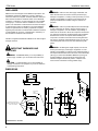
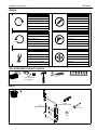
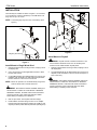
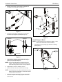
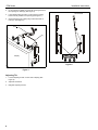
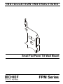
INSTALLATION INSTRUCTIONS
Small Flat Panel Tilt Wall Mount
Spanish Product Description
German Product Description
Portuguese Product Description
Italian Product Description
Dutch Product Description
French Product Description
FPM Series
FPM Series
Installation Instructions
DISCLAIMER
Milestone AV Technologies and its affiliated corporations and
subsidiaries (collectively "Milestone"), intend to make this
manual accurate and complete. However, Milestone makes no
claim that the information contained herein covers all details,
conditions or variations, nor does it provide for every possible
contingency in connection with the installation or use of this
product. The information contained in this document is subject
to change without notice or obligation of any kind. Milestone
makes no representation of warranty, expressed or implied,
regarding the information contained herein. Milestone assumes
no responsibility for accuracy, completeness or sufficiency of
the information contained in this document.
Chief® is a registered trademark of Milestone AV Technologies.
All rights reserved.
IMPORTANT WARNINGS AND
CAUTIONS!
WARNING: A WARNING alerts you to the possibility of
serious injury or death if you do not follow the instructions.
WARNING: Failure to read, thoroughly understand, and
follow all instructions can result in serious personal injury,
damage to equipment, or voiding of factory warranty! It is the
installer’s responsibility to make sure all components are
properly assembled and installed using the instructions
provided.
WARNING: Failure to provide adequate structural strength
for this component can result in serious personal injury or
damage to equipment! It is the installer’s responsibility to
make sure the structure to which this component is attached
can support five times the combined weight of all equipment.
Reinforce the structure as required before installing the
component. The wall to which the mount is being attached
may have a maximum drywall thickness of 5/8" (1.6cm). Do
not install drywall anchors into the seam between drywall
pieces.
WARNING: Exceeding the weight capacity can result in
serious personal injury or damage to equipment! It is the
installer’s responsibility to make sure the combined weight of
all components attached to the mount does not exceed 45 lbs
(20.4 kg) for wood stud installation OR 30 lbs (13.6 kg) for
drywall installation. Use with products heavier than the
maximum weight indicated may result in collapse of the
mount and its accessories causing possible injury.
CAUTION: A CAUTION alerts you to the possibility of
damage or destruction of equipment if you do not follow the
corresponding instructions.
DIMENSIONS
3.68
3.45
5.63
1.29
FACE TILTS
5 UP
18 DOWN
.60
2.13
2.25
1.13
.38
MOUNTING BUTTONS ON
INTERFACE BRACKET FIT INTO
SLOTS ON MOUNT
1.50
4.38
3.63
1/4 x 3/8 SLOT
DIMENSIONS: INCHES
2
Installation Instructions
FPM Series
LEGEND
Tighten Fastener
Pencil Mark
Apretar elemento de fijación
Marcar con lápiz
Befestigungsteil festziehen
Stiftmarkierung
Apertar fixador
Marcar com lápis
Serrare il fissaggio
Segno a matita
Bevestiging vastdraaien
Potloodmerkteken
Serrez les fixations
Marquage au crayon
Loosen Fastener
Drill Hole
Aflojar elemento de fijación
Perforar
Befestigungsteil lösen
Bohrloch
Desapertar fixador
Fazer furo
Allentare il fissaggio
Praticare un foro
Bevestiging losdraaien
Gat boren
Desserrez les fixations
Percez un trou
Phillips Screwdriver
Adjust
Destornillador Phillips
Ajustar
Kreuzschlitzschraubendreher
Einstellen
Chave de fendas Phillips
Ajustar
Cacciavite a stella
Regolare
Kruiskopschroevendraaier
Afstellen
Tournevis à pointe cruciforme
Ajuster
TOOLS REQUIRED FOR INSTALLATION
#2
1/8" (wood stud)
3/8" (drywall)
PARTS
A (1)
[FPM Assembly]
B (4)
10-24
[Hollow wall anchor]
D (2)
#10 x 2-1/2"
C (4)
#10
3
FPM Series
Installation Instructions
INSTALLATION
The FPM may be installed on either a single 2" x 4" wood stud,
or on drywall (1/2" minimum thickness). The FPM allows a tilt
range from 5° up to 18° down.
2
x2
NOTE: The latching flag may be moved, if necessary. (See
4
x2
Figure 1)
5
(D) x 2
Flag
(A)
(C)
Figure 2
Flag may be moved
Install Mount to Drywall
WARNING: Drywall must be a minimum thickness of 1/2"
Figure 1
and a maximum thickness of 5/8". Do not install drywall
anchors into the seam between drywall pieces.
Install Mount to Single Wood Stud
1.
Determine approximate mounting location, keeping in mind
the display size.
1.
Determine approximate mounting location, keeping in mind
the display size.
2.
Use a stud sensor to locate applicable wood stud. Mark
location with a pencil.
2.
3.
Level FPM assembly (A) at desired height and, using it as a
template, mark the location of upper and lower pilot holes.
Ensure marks are in the center of wood stud.
Level FPM assembly (A) at desired height and, using it as a
template, mark the location of the four anchor holes (one in
each corner slot).
NOTE: Mount can provide ±1/2" of lateral shift by using mount
holes on either side of vertical center line.
WARNING: ELECTRICAL SHOCK HAZARD! Drilling into
electrical wires or cables can cause DEATH or SERIOUS
PERSONAL INJURY! ALWAYS make certain area behind
mounting surfaces is free of electrical wires and cables
before drilling or installing mount fasteners.
4.
Drill 1/8" pilot holes. Ensure pilot holes are straight.
5.
Fasten FPM to wood stud using two #10 x 2-1/2" Phillips
head screws (D) through two #10 washers (C), FPM (A), and
drywall (not shown) and install into pilot holes. (See Figure 2)
4
WARNING: ELECTRICAL SHOCK HAZARD! Drilling into
electrical wires or cables can cause DEATH or SERIOUS
PERSONAL INJURY! ALWAYS make certain area behind
mounting surfaces is free of electrical wires and cables
before drilling or installing mount fasteners.
Installation Instructions
3.
FPM Series
Drill 3/8" anchor holes. Ensure holes are straight and
completely through drywall. (See Figure 3)
(A)
4
2
(B) x 4
x4
3
(B)
Anchor x 4
screws
8
5
x4
(C) x 4
Figure 3
4.
Gently tap anchor (B) into anchor hole. Anchor barbs
should be fully engaged in drywall (See Figure 4).
Anchor not
collapsed
Drywall
Anchor
collapsed
Figure 5
Install Display to Mount
NOTE: Proper interface must be attached to display. Follow
instructions included with interface assembly.
1.
Open latching flag by rotating flag clockwise on FPM (A).
(See Figure 6)
Latching
flag closed
Anchor barb
Latching
flag open
1
Figure 4
5.
Using Phillips screwdriver, tighten anchor screw until
anchor has fully collapsed against back side of drywall.
(See Figure 3) and (See Figure 4)
NOTE: Anchor screw will feel tight until anchor begins to
collapse. Screw will then turn easier for many turns.
Screw will feel tight when anchor has fully collapsed.
6.
Repeat Steps 4 and 5 for remaining anchors.
7.
Remove and retain anchor screws from anchors (B).
NOTE: Anchors (B) may come with small washers which may
Figure 6
be left on the screw or discarded. These small washers
do NOT replace washers (C).
8.
Insert anchor screws through washers (C), FPM (A) and
install into collapsed anchors (B). Tighten until secure.
(See Figure 5)
5
FPM Series
Installation Instructions
2.
Lift and maneuver display such that all mounting buttons fit
into openings on FPM (A). (See Figure 7)
3.
Lower display firmly into place. Ensure each mounting
button has fully seated in the opening (See Figure 7)
4.
Close latching flag by rotating flag counterclockwise on
FPM (A). (See Figure 7)
10° Tilt Down
Latching
flag
4
(A)
2
3
Display
1
2
Figure 8
Figure 7
Adjusting Tilt
1.
Loosen adjusting screws on each side of display (See
Figure 8).
2.
Adjust tilt as desired.
3.
Retighten adjusting screws.
6
3
Installation Instructions
FPM Series
7
FPM Series
Installation Instructions
USA/International
Europe
Chief Manufacturing, a products division
of Milestone AV Technologies
8803-000034 RevD
2011 Milestone AV Technologies, a
Duchossois Group Company
www.chiefmfg.com
09/11
Asia Pacific
A
P
F
A
P
F
A
8401 Eagle Creek Parkway, Savage, MN 55378
800.582.6480 / 952.894.6280
877.894.6918 / 952.894.6918
Fellenoord 130 5611 ZB EINDHOVEN, The Netherlands
+31 (0)40 2668620
+31 (0)40 2668615
Office No. 1 on 12/F, Shatin Galleria
18-24 Shan Mei Street
Fotan, Shatin, Hong Kong
P 852 2145 4099
F 852 2145 4477