1
Application Note 005
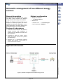
Automatic management of two different energy
sources
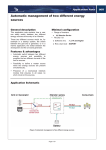
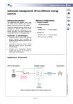
General description
This application note explains how a user
can easily switch between two different
energy sources at the entry of an Xtender.
These two different sources would be, for
example in a backup system, the switch
between the grid and a generator, or in a
marine application, the switch between the
shorepower and the on board generator.
Minimal configuration
Range of inverters
o
All Xtender Series
RCC02 / 03
o Software vers.
: 1.3.14 and higher
o RCC User level : EXPERT
Features & advantages
Automatic switch between two different
energy sources and possibility to
program the two different currents of the
two ac sources.
Possibility to define a master source
when two energy sources are present
simultaneously.
Presence of a mechanical interlock
module that ensures in all cases no
short circuit on the sources.
Application Schematic
Page 1 / 9
AN-005-V.2.2.3-08 | © STUDER INNOTEC
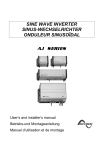
(Figure 1) Automatic management of two different energy sources
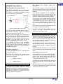
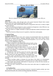
Detailed description
For example, the computer system of a
company…
The automatic AC transfer switch
This computer system is connected to the grid
(like any other consumer) but it is the system
that can not afford a power outage in case of a
blackout.
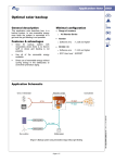
This particular application is a set composed of
three relays and two time-delay relays to detect
the presence or absence of different energy
sources at the entry of the system.
It is therefore necessary for the company to
have a second source of energy only for the
computer system. (Backup source consists of a
generator, a battery and an inverter-charger).
For this reason, the second ac source may be
less powerful than the grid. For example, the
current delivered by the grid is 40A while the
current drawn by the computer system is only
8A. So the generator should be sized for 8 to
10A.
The backup runs on batteries and if the blackout
is too long, the generator is started.
(Figure 2) Automatic AC transfer switch
The user can define a master source in case of
simultaneous presence of the two different
energy sources (see situation 4 p.3).
Also, the user can program the current of the
two ac sources. The Xtender will automatically
select the predefined current depending on the
connected ac source. With the remote entry, the
Xtender is informed about which of the ac
source is selected to set the proper current.
It is possible to order all the necessary
equipment at Studer Innotec. Note that Studer
Innotec does not supply prewired mounting for
this application. (Scheme and list of equipment
available on page 5).
Function description
To better illustrate this function, we will take two
concrete examples.
Note also that there are two general cases
involving the use of different energy sources at
the entry of an Xtender :
1.
Backup systems
2.
Marine systems
In normal case the max. current of the ac
source = 40A and in backup case the max.
current of the ac source = 10A.
Marine systems
In the case of a boat equipped with an on board
generator. When the boat is at sea, the energy
source is the on board generator. But when the
boat is moored into port, the energy source is
also the shorepower. In most cases, these two
ac sources have different powers.
The on board generator might provide 16A as
the shorepower only 8A. This will require many
changes during docking or departure at sea of
the boat.
With the automatic management of two different
energy sources, all these changes belong to the
past.
For example, back to our boat…
A boat docked at the port during the night will be
connected to the dock (max. current of the ac
source = 8A). When the boat goes at sea, its
power source becomes the generator (max.
current of the ac source = 16A).
At midday, the boat returns to port and connects
back to the dock (max. current of the ac source
= 8A).
Backup systems
In the case of a system requiring no power
interruption (backup system), there could be two
different ac sources, for example the grid and a
generator. The automatic AC transfer switch will
automatically connect to the second source in
case for example of a blackout.
The boat heads for sea again for the afternoon
and uses the generator as energy source (max.
current of the ac source = 16A).
Page 2 / 9
005
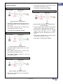
System situations
The contact “remote entry” is still open. (max.
current of the ac source = 15A)
Situation 1
The battery is automatically charged.
Situation 4
(Figure 3) System on grid connected
The power is delivered from the grid (or for a
marine application from the shorepower), AC
out = AC in.
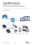
(Figure 6) System simultaneously connected the grid
and on a generator
The contact “remote entry” is closed. (max.
current of the ac source = 10A)
There are two energy sources on the system
but the master source selected is the grid.
The battery is automatically charged.
The power is delivered from the master
source, here the grid (or for a marine
application from the shorepower), AC out =
AC in.
Situation 2
The contact “remote entry” is closed. (max.
current of the ac source = 10A)
The battery is automatically charged.
(Figure 4), System in mode "stand-alone"
The grid is disconnected, there is no more
power on AC in.
The contact “remote entry” is open. (max.
current of the ac source = 15A)
The battery supplies energy to AC out
through the inverter.
Situation 3
(Figure 5) System on generator connected
The power is delivered from the generator,
AC out = AC gen.
Page 3 / 9
005
005
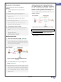
Parameters & descriptions
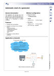
Automatic generator startup (Optional)
For backup systems, it is obviously convenient
to have a fully automated system. Thus it is
possible in case of blackout and under-voltage
battery to start the generator automatically i.
Three parameters allow controlling this
function :
1. “Use an alternate max. input current”
{1566}.
This is possible with the Xtender and one of its
auxiliary contacts.
└> authorize the use of a second energy
source at the input of the system.
Set as YES
2. “Alternate max. input current” {1567}.
└> is the value of the power ac source of the
second energy source.
Set according to the size of the circuit
breaker or the grid capacity.
3.
“Remote entry active” {1545}.
(Figure 8) System with an automatic generator startup
└> This parameter allows you to determine if
the command entry is activated closed or
open.
Notes
Associated application notes :
Set as active open
(Master source = closed)
(Second source = open)
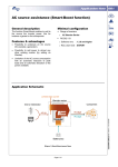
AN001 AC source assistance (Smart-Boost function)
i
Additional function
1. “Smart-Boost allowed” {1126}. (Optional)
└> helps the generator by adding the missing
power. Prevents from overloading the input
even if consumers are higher than the input
source (grid or generator).
Set as YES
(Figure 7), System with the Smart-Boost function
activated
2. “Immediate detection of input voltage loss”
{1435}. (Optional)
└> Allows to starting the inverter mode as quick
as possible in case of fluctuations of the
AC-in grid. This function is useful when it
comes to very sensitive loads that require
an uninterruptible power supply (UPS).
Set as YES
Page 4 / 9
Only possible with a generator equipped with an
automatic start
005
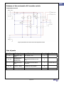
Scheme of the automatic AC transfer switch
Independent neutral
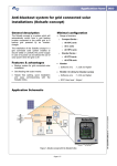
(Figure 9) Automatic AC transfer switch with independent neutral
List of parts
Part Name
Designation
Studer reference
Quantity Specification
K1
Installation relay
[16A]
REL-INSTAL-16A
1
K2, K3
Contactor threephase [AllenBradley 32A]
REL-CONTACTEUR-3L-32A230V
2
-
Mechanical lock
block
REL-CONTACTEUR-BLOCVERROU
1
F1, F2
Fuse block [Woertz
– 4mm2 – Grey]
B-WOERTZ-4#-FUSIBLE
2
K4, K5
Time-delay relay
REL-INSTAL-RETARD-5A
2
Page 5 / 9
For K2 and K3
Time-delay = 2s
005
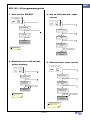
RCC -02 / -03 programming guide
1. User level to EXPERT
3. Use an alternate max. input
current
Press SET and search with
:
Press SET and search with
:
User level {5012}
System {1101}
Press SET and insert the code i :
Press SET and search with
42 64 68
Remote entry
(Remote ON/OFF)
{1537}
Press SET :
Press SET and search with
Your level is
EXPERT
i
:
:
Use an alternate
max input current
{1566}
The code is available in the
user manual RCC -02 / -03
Press SET, selection Yes
with
and press SET :
The alternate max
input current is
activated
2. Maximum source AC current
(power sharing)
4. Alternate max. input current
Press SET and search with
Press SET and search with
System {1101}
Basic settings {1100}
Press SET and search with
Press SET and search with
:
:
Remote entry
(Remote ON/OFF)
{1537}
Max source AC
current (Power
Sharing) {1107}
Press SET, adjust the desired
value i with
and press SET :
Press SET and search with
Your input current is
adjusted
i
:
:
:
Alternate max input
current {1567}
Press SET, adjust the desired
value i with
and press SET :
The current value [Aac] must be
set according to the size of the
circuit breaker or the grid
capacity
Your input current is
adjusted
i
Page 6 / 9
The current value [Aac] must be
set according to the size of the
circuit breaker or the grid
capacity
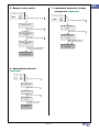
5. Remote entry active
005
7. Immediate detection of input
voltage loss (optional)
Press SET and search with
:
Press SET and search with
:
System {1101}
Press SET and search with
:
Press SET and search with
Remote entry
(Remote ON/OFF)
{1537}
Press SET and search with
:
The mode UPS is
selected
Press SET, selection Open
with
and press SET :
The remote entry is
active as Open
6. Smart-Boost allowed
(optional)
:
Basic settings {1100}
Press SET and search with
:
Lockings {1123}
Press SET and search with
Immediate detection
of input voltage loss
{1435}
Press SET, selection Yes
with
and press SET :
Remote entry active
{1545}
Press SET and search with
AC-IN and Transfer
{1197}
:
Smart-Boost allowed
{1126}
Press SET, selection Yes
with
and press SET :
The Smart-Boost is
allowed
Page 7 / 9
:
005
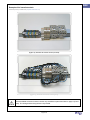
Example of AC transfert switch
Fieldtests and pictures by STUDER Innotec ( http://www.studer-innotec.com )
(Figure 10), Automatic AC transfer switch (not wired)
(Figure 11), Automatic AC transfer switch (wired)
The kit available at Studer Innotec includes only the different parts described on page 5 (List of
parts). The wiring and the fixing rail are not provided.
Page 8 / 9
005
Notes
__________________________________________________________________________________
__________________________________________________________________________________
__________________________________________________________________________________
__________________________________________________________________________________
__________________________________________________________________________________
__________________________________________________________________________________
__________________________________________________________________________________
__________________________________________________________________________________
__________________________________________________________________________________
__________________________________________________________________________________
__________________________________________________________________________________
__________________________________________________________________________________
__________________________________________________________________________________
__________________________________________________________________________________
__________________________________________________________________________________
__________________________________________________________________________________
__________________________________________________________________________________
__________________________________________________________________________________
__________________________________________________________________________________
__________________________________________________________________________________
__________________________________________________________________________________
__________________________________________________________________________________
__________________________________________________________________________________
Worldwide sales and service
Switzerland
Studer Innotec
Rue des Casernes 57
1950 SION / Switzerland
Tel :027 205 60 80 / Fax : 027 205 60 88
Email : [email protected]
Web : http://www.studer-innotec.com
Limitation of responsibility
The use of STUDER INNOTEC devices is the responsibility of the customer in all cases. STUDER INNOTEC reserves the right to
make any modifications to the product without prior notification.
Page 9 / 9