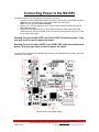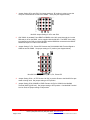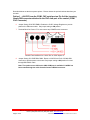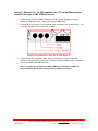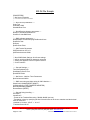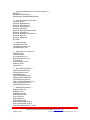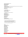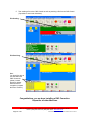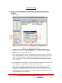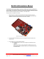
1
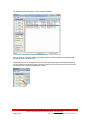
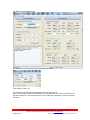
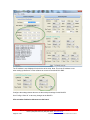
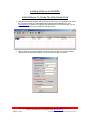
Mx1053 UNI Installation Manual (Ax2200 Board) The Universal Network Interface (UNI) is connected to a CNC control. The UNI “virtualizes” the local serial port to an IP Address & TCP port for remote access by Ethernet enabled software. On the UNI, COM1 is reserved for the serial port to the control (also called Port D internally). All ports have pin 9 capable of bringing in power (12-24VDC) – see Jumper JP33. The usual order of installation is as follows: 1. With the power off, install the UNI noting the power supply and cable connections. Usually a serial cable will be supplied, but in case it is not the DB9 on the UNI is like a standard PC serial port with pin 9 being a power input (or output). Mx1053 Universal Network Interface – Rev 7 2. Connect the UNI RJ-45 Ethernet port up to a working CAT5 cable connected to the corporate LAN. 3. On your DNC server, load the supplied software: a. Install the AxHDU Utility from the CD and configure the Ax2200 then install i. MxServer ii. NetDNC NOTE: It is important to configure Net-DNC and MxServer in the order indicated above. When using the software, you must start MxServer prior to any DNC system. Memex Automation Inc., 200 – 3425 Harvester Rd., Burlington, ON Canada L7N 3N1 Phone: (905) 635-1540 Fax: (905) 631-9640 www.memex.ca Page 1 of 20 \ISO9000\DOCs\M100728F - UNI Pictorial Installation Manual - MAI.doc Connecting Power to the Mx1053 The Mx1053 UNI can be powered by three methods, as follows: 1. +24 VDC from the COM1 CNC serial port on Pin 9 of the incoming female DB9 connector attached to the CNC data port of the control (COM1 CNC Connector) NOTE: Use this option for Fanuc Controls. 2. External +18 – 24 VDC applied to the J7 Terminal Block Header located to the right of DB9 COM3 serial port. 3. External +5 VDC applied to the J7 Terminal Block Header located to the right of DB9 COM3 serial port. JP10, Reg ENBL, does not need to be jumpered if 5VDC is to be used for the main power supply. Warning: Do not use both 5VDC and 18 to 24 VDC for external power. Only one type must be used to power the board. Warning: Do not use both +24VDC from COM1 CNC serial port and external power. Only one type must be used to power the board. To set the jumper settings on the Mx1053 upon which the Ax2200HS has been placed, follow the instructions 1 to 8 below. Mx1053 Power and Jumper Setting Memex Automation Inc., 200 – 3425 Harvester Rd., Burlington, ON Canada L7N 3N1 Phone: (905) 635-1540 Fax: (905) 631-9640 www.memex.ca Page 2 of 20 \ISO9000\DOCs\M100728F - UNI Pictorial Installation Manual - MAI.doc 1. Jumper Setting JP31 and JP32: Set jumper setting to “B” position in order to route the com port of the Ethernet module to the COM1 – CNC port (see diagram below). Mx1053 Jumper Setting for JP31 and JP32 2. CNC COM1: A standard Fanuc DB9F to DB25M, with +24V routed through pin 9 on the DB9 and pin 25 on the DB25, can be supplied with the Mx1053. The DB9F of the cable is connected to the CNC port of the Mx1053 and the DB25M is connected to the DB25F RS232 serial port of a Fanuc CNC machine. 3. Jumper Setting P1, P3, P4 and P5: Reroutes the RJ12 Mx2000 HOI Terminal Signal to COM2 as well as COM3. Set jumper setting to “D” position (see diagram below). Mx1053 RJ12 Jumper Setting for P1, P3, P4 and P5 4. Jumper Setting JP16 + 24 TR: Routes +24 VDC to provide Power to the Mx1053 if a tape reader is being used. Set jumper setting to OFF position. 5. Jumper Setting JP33 COM3/RJ12 PWR: Routes +9 VDC to COM3 for the Mx2000 Terminal (9VDC @ 350 mA). Set jumper setting to OFF position. If an Mx2000 Terminal is to be used, set jumper setting to ON position. Memex Automation Inc., 200 – 3425 Harvester Rd., Burlington, ON Canada L7N 3N1 Phone: (905) 635-1540 Fax: (905) 631-9640 www.memex.ca Page 3 of 20 \ISO9000\DOCs\M100728F - UNI Pictorial Installation Manual - MAI.doc Described below are the three power options. Please choose the option that best describes your scenario. Option 1 - +24 VDC from the COM1 CNC serial port on Pin 9 of the incoming female DB9 connector attached to the CNC data port of the control (COM1 CNC Connector) 6. Jumper Setting JP10 REG ENBL: Enables the 5V DC Voltage Regulator to provide power to the Ethernet module. Set jumper setting to ON position. 7. Terminal Block for Power J7: Do not connect any POWER to this connector. Mx1053 Terminal Block for =18-24 VDC or 5VDC Option J7 8. Jumper Setting JP1 PWR DB9-COM1: Routes +24 VDC from Pin 9 of COM1 DB9 connector to provide power to the board. Set jumper setting to ON position if routed through DB9 COM1 cable. Note: The option to use +24V on the CNC COM1port is available if +24VDC has been routed through the cable from the Control’s RS232 connector. Memex Automation Inc., 200 – 3425 Harvester Rd., Burlington, ON Canada L7N 3N1 Phone: (905) 635-1540 Fax: (905) 631-9640 www.memex.ca Page 4 of 20 \ISO9000\DOCs\M100728F - UNI Pictorial Installation Manual - MAI.doc Option 2 - External +18 – 24 VDC applied to the J7 Terminal Block Header located to the right of DB9 COM3 serial port. 6. Jumper Setting JP10 REG ENBL: Enables the 5V DC Voltage Regulator to provide power to the Ethernet module. Set jumper setting to ON position. 7. Terminal Block for Power J7: Route external power to provide power to the Mx1053. +18 to 24 VDC and GND on Pin 3 (see Item 3, below). Mx1053 Terminal Block for =18-24 VDC or 5VDC Option J7 8. Jumper Setting JP1 PWR DB9-COM1: Routes +24 VDC from Pin 9 of COM1 DB9 connector to provide power to the board. Set jumper setting to OFF position if +24VDC is not being routed through DB9 Connector. 9. Note: The option to use +24V on the CNC COM1port is available if +24VDC has been routed through the cable from the Control’s RS232 connector. Memex Automation Inc., 200 – 3425 Harvester Rd., Burlington, ON Canada L7N 3N1 Phone: (905) 635-1540 Fax: (905) 631-9640 www.memex.ca Page 5 of 20 \ISO9000\DOCs\M100728F - UNI Pictorial Installation Manual - MAI.doc Option 3 - External +5 VDC applied to the J7 Terminal Block Header located to the right of DB9 COM3 serial port. JP10, Reg ENBL, does not need to be jumpered if 5VDC is to be used for the main power supply. 6. Jumper Setting JP10 REG ENBL: Enables the 5V DC Voltage Regulator to provide power to the Ethernet module. Set jumper setting to OFF position. 7. Terminal Block for Power J7: Route external power to provide power to the Mx1053. +5 VDC on Pin 2 (see Item 2, below) and GND on Pin 3 (see Item 3, below). Mx1053 Terminal Block for =18-24 VDC or 5VDC Option J7 8. Jumper Setting JP1 PWR DB9-COM1: Routes +24 VDC from Pin 9 of COM1 DB9 connector to provide power to the board. Set jumper setting to OFF position if +24VDC is not being routed through DB9 Connector. Note: The option to use +24V on the CNC COM1port is available if +24VDC has been routed through the cable from the Control’s RS232 connector. Memex Automation Inc., 200 – 3425 Harvester Rd., Burlington, ON Canada L7N 3N1 Phone: (905) 635-1540 Fax: (905) 631-9640 www.memex.ca Page 6 of 20 \ISO9000\DOCs\M100728F - UNI Pictorial Installation Manual - MAI.doc Use AxHDU To Configure The UNIs Over the LAN Mx1053 – Ax2200HS - Configuration Summary 1. At a PC station, if the AxHDU (High Speed Deployment Utility) software is not already installed, please install it now. 2. Launch the AxHDU software. 3. Click on the Search button to search for any Mx1053s on the Network. The Mx1053 is shipped using DHCP mode. 4. Click on the Device with the appropriate MAC address to highlight it and click on setup. This will bring up a window that will provide information on the serial configuration of the Mx1053 and the Network information of the Ax2200HS device. To change the IP address to a Static IP address, uncheck Enable DHCP and insert the IP Address, Subnet Mask and Gateway Address. (Note: It is advisable to change the IP address from DHCP to a static IP address once it is seen on the network.) For the Serial port settings, the CNC setting for the Ax2200HS is the only section that needs to be modified. It needs to match the control that the Mx1053 is attached to. a. b. c. d. e. f. Serial Baud Rate. Data Bits. Parity Bits. Stop Bits. Flow Control. Wait for XON. After the Serial and Network Settings has been updated, write the configuration to the Mx1053 by going to the top left of the configuration menu and clicking on Config Write All. Click on Exit to leave the configuration menu. 5. The serial and network configuration has now been completed. Using the AxHDU Utility Go to Start > Programs > AxHDU and click on the menu item. Memex Automation Inc., 200 – 3425 Harvester Rd., Burlington, ON Canada L7N 3N1 Phone: (905) 635-1540 Fax: (905) 631-9640 www.memex.ca Page 7 of 20 \ISO9000\DOCs\M100728F - UNI Pictorial Installation Manual - MAI.doc The UMI HS Deployment utility’s search window will appear. Click on “Search” to poll the network for Ax2200 network modules attached to the Mx1053 UNI and display a list of devices found. Identify the device to be configured on the Device list by comparing the MAC address display to the one printed on the Mx1053 (Silver Lantronix module). Click on the device on the list and click on ‘Setup’ button to open its configuration window. Memex Automation Inc., 200 – 3425 Harvester Rd., Burlington, ON Canada L7N 3N1 Phone: (905) 635-1540 Fax: (905) 631-9640 www.memex.ca Page 8 of 20 \ISO9000\DOCs\M100728F - UNI Pictorial Installation Manual - MAI.doc The Setup utility window appears. Click Config > Read > All The status window will refresh and the device will respond in the list. Note: This will fail to connect to the AxHS2200 if other application is currently connected to this machine’s 4444 port. You must disconnect or turn off the other application in order to configure the board. Memex Automation Inc., 200 – 3425 Harvester Rd., Burlington, ON Canada L7N 3N1 Phone: (905) 635-1540 Fax: (905) 631-9640 www.memex.ca Page 9 of 20 \ISO9000\DOCs\M100728F - UNI Pictorial Installation Manual - MAI.doc The IP address is now displayed for the device to be setup. Note: This is the IP address to use when setting up MxServer or other software to connect to the Mx1053 for DNC. Configure the settings shown above to set the serial port settings for this Mx1053. Use “Config-> Write All” to save any changes to the Mx1053. Click exit when finished to disconnect to the board. Memex Automation Inc., 200 – 3425 Harvester Rd., Burlington, ON Canada L7N 3N1 Phone: (905) 635-1540 Fax: (905) 631-9640 www.memex.ca Page 10 of 20 \ISO9000\DOCs\M100728F - UNI Pictorial Installation Manual - MAI.doc Installing MxServer and NetDNC Install MxServer To Create The Virtual Serial Ports 1. With the UNI installed properly and configure, we now have to set up MxServer to create the virtual local serial port. Install MxServer (Download ‘MxSvr###NT5.exe’ from www.memex.ca or locate on a supplied CD) and follow the on screen prompts. The run the MxServer shortcut on the desktop to see this screen: 2. Add a machine (or select the default) and hit the yellow IP button to configure MxCom properties for the first UNI (machine). You should see this type of a screen. Memex Automation Inc., 200 – 3425 Harvester Rd., Burlington, ON Canada L7N 3N1 Phone: (905) 635-1540 Fax: (905) 631-9640 www.memex.ca Page 11 of 20 \ISO9000\DOCs\M100728F - UNI Pictorial Installation Manual - MAI.doc 3. After you have created all the virtual ports you need to finish it off with configuring some MxServer settings as follows (as an example): After emulating the above, hit APPLY to set the data. The information is stored in the Mx.INI file if you want to inspect or manipulate it later. If you select a machine and double click, you will see the following. Note that the Serial Port is created, but not OPENED until Net-DNC opens. It should also connect to the UNI that you are pointing to. Memex Automation Inc., 200 – 3425 Harvester Rd., Burlington, ON Canada L7N 3N1 Phone: (905) 635-1540 Fax: (905) 631-9640 www.memex.ca Page 12 of 20 \ISO9000\DOCs\M100728F - UNI Pictorial Installation Manual - MAI.doc MX.INI File Sample [PROPERTIES] ;** Mx Server Properties ;** ===================== ; ;---- Auto connect parameters ---Auto=True AutoDelay=1000 ShowWindow=True ; ;---- Send/Receive directory parameters ---RecDir=C:\Net-DNC\Send\receive SendDir=C:\Net-DNC\Send ; ;---- DNC software parameters ---DNCSoftware=C:\Net-DNC\program\Dncwin32.exe RunDNC=False DirScan= RunDirScan=False ; ;---- UMI Tracker Parameters UMITrackerHost=127.0.0.1 UMITrackerInterval=15000 ; ; ;** Net COM Default Settings. All of these settings ;** will be used be all NetCom instances unless the ;** setting also appears in the Port specific section ;** for the machine ; ;---- General Settings ---TimeOutGranularity=50 SendStateToServer=True RunAsEXE=False ; ;---- Net Server - NetCom Timer Parameters NetComInterval=30000 ; ;---- DNC reset string and Abort string for CNC Machine ---AbortCmd=%|O8003|(RESET)|M30|%| CNCAbortString=(FILE TRANSFER ABORTED) BarCodeAbortString=ABORT RemoteReset=(RESET) ; ;---- General String Handling ---CrLfChar=| InsertChar=^ ; Format of the TranslateChar string: "##>##, ##>##" (and etc). ; Translating is done by specifying the Ascii decmial value of the char to translate and the decimal value of the char to ;translate to. Such as: 65>67 = 'A' to 'C' ;TranslateChars=65>67 ; Memex Automation Inc., 200 – 3425 Harvester Rd., Burlington, ON Canada L7N 3N1 Phone: (905) 635-1540 Fax: (905) 631-9640 www.memex.ca Page 13 of 20 \ISO9000\DOCs\M100728F - UNI Pictorial Installation Manual - MAI.doc ;---- Command parameters for file send and barcode ---BarCode=* MaxBarCodeFileChars=30 RemoteSend=%|O8004|(SND^)|M30|% ; ;---- Command parameters for HSL ---HSLCmd_Dir=X4 HSLCmd_DirStartDelim=[ HSLCmd_DirEndDelim=] HSLCmd_Download=AD ^ HSLCmd_Upload=RL HSLCmd_UploadResponse=LOAD HSLCmd_UploadFile=^ HSLCmd_UploadDone=Added File HSLCmd_Abort=X9 HSLCmd_Delete=DP ^ Ext=False ; ;---- TelNet Settings ---TelnetDataPort=False TelnetBarcodePort=False TelnetHSLPort=False ; ;---- Debug and Trace Settings ---DebugFile=False TraceFile=False ErrorLoggingOn=True DebugFilesCloseSecs=10 TraceLevel=4 TraceToWindow=False UseEcho=False CheckChar=~ ; ;---- VSP Handling Settings ---VSPortSoftControl=False VSPortInputSize=8192 PortOffMaxSecs=0 PortFlushDelaySeconds=2 VSPProcessPeriodMS=200 VSPStopCheckingLimit=5 VSP_ForceXOFFInRxChar=True VSP_EnableHWFlow=True VSPPortEmptyTimeout=1 ; ;---- UMI Handling Settings ---UMIPacketSize=511 UMINAKLimit=0 UMINAKDelay=100 UMITimeOut=10000 UMI_AckChar=6 UMI_NakChar=21 UMI_EOBChar=165 UMI_ClearBufferDB_Cmd=3 UMI_ClearBufferUB_Cmd=4 UMI_SetPortWaitForXOFF_Cmd=0 Memex Automation Inc., 200 – 3425 Harvester Rd., Burlington, ON Canada L7N 3N1 Phone: (905) 635-1540 Fax: (905) 631-9640 www.memex.ca Page 14 of 20 \ISO9000\DOCs\M100728F - UNI Pictorial Installation Manual - MAI.doc UMI_SetPortWaitForXON_Cmd=0 UMI_Escape_Cmd=27 MxClear=(MXCLEAR) UseMxClear=False UseRabbit=True ; PassFilter is a comma delimited string that specifies the decimal value to be passed when filtering valid characters ; values being filtered are: 0,1,2,5,6,7,8,9,11 ;PassFilter=0,1,2,3,4,5,6,7,8,9,10,11 AtomicChar1=13 AtomicChar2=10 ; ;---- Socket Settings ---SocketConnectTimeout=5000 SocketTimerC=5000 SocketTimerD=30000 ; ;---- Socket Failure and Detection Settings ---NoTrafficSecs=5 NoHSLActivitySecs=5 NoBarCodeTrafficSecs=5 PollPeriodSecs=10 RecoveryPeriodSecs=60 PingAttemptsMax=2 PingTimeout=500 UsePing=True UsePoll=True UseTracker=False UseBarScanner=False HandheldSend=%|O8004|(SEND-^)|M30|% ; ;**** END OF MAIN PROPERTIES PARAMETERS **** '** Note that any of the default settings above may be over '** written by placing an entry for the setting in the '** Port section corresponding to the machine in question ; ;*********************************************** [Port0] MachineName=UNI PortAddress=10.10.1.39 HSLPort=1000 DataPort=4444 BarCodePort=4321 PortName=COM35 UseRabbit=False UseMxClear=False Deleted=False EnableData=True EnableBarCode=False EnableHSL=False DebugFile=True TraceFile=False AutoLoad=True Memex Automation Inc., 200 – 3425 Harvester Rd., Burlington, ON Canada L7N 3N1 Phone: (905) 635-1540 Fax: (905) 631-9640 www.memex.ca Page 15 of 20 \ISO9000\DOCs\M100728F - UNI Pictorial Installation Manual - MAI.doc Installing Net-DNC After MxServer 1. Net-DNC can now be started from the Net Console (or if AUTO mode is enabled, it will start on the next MxSrv.exe mount. Note that MxServer must be running before Net-DNC as it reads the available serial ports at the start and the virtual ones must be available. You will see something like the screens below. 2. Click on Setup and select the COM Setup tab: Memex Automation Inc., 200 – 3425 Harvester Rd., Burlington, ON Canada L7N 3N1 Phone: (905) 635-1540 Fax: (905) 631-9640 www.memex.ca Page 16 of 20 \ISO9000\DOCs\M100728F - UNI Pictorial Installation Manual - MAI.doc From the SETUP tab you can setup a new COM port (in this case COM10) to talk with the machine tool virtually through our UNI. Make sure that you select XON/XOFF & RTSCTS for flow control. If COM10 is not available, you may need to restart Net-DNC or shut down Net-DNC & MxServer. Note: MxServer must show ‘Created’ under its port status to be seen or connected properly under Net-DNC . 3. The Special Tab: Allows for some additional behavior changes during the file transfer process. Note: Change the File Start / End characters to match a unique character set found in your part program files. Leave blank to send everything in the file. 4. Put the machine setup into REMOTE Mode (yellow) and test the configuration. Memex Automation Inc., 200 – 3425 Harvester Rd., Burlington, ON Canada L7N 3N1 Phone: (905) 635-1540 Fax: (905) 631-9640 www.memex.ca Page 17 of 20 \ISO9000\DOCs\M100728F - UNI Pictorial Installation Manual - MAI.doc 5. Test sending a file to the CNC Control as well as punching a file from the CNC Control (if possible to test in both directions). File Sending: File Receiving: Note: You should be able to see data within the CNC Viewer tab (shown) in both directions without data loss and/or corruption (compare the files to confirm). Congratulations, you are done installing a DNC Connection. Repeat for all other Machines Memex Automation Inc., 200 – 3425 Harvester Rd., Burlington, ON Canada L7N 3N1 Phone: (905) 635-1540 Fax: (905) 631-9640 www.memex.ca Page 18 of 20 \ISO9000\DOCs\M100728F - UNI Pictorial Installation Manual - MAI.doc Troubleshooting Q. Why can’t I find the Ax2200HS on the network when I do a Search using Broadcast? A. Use IP Scan to scan for a particular IP Range and identify the Lantronix device on the Ax2200HS. 1. Open AxHDU. Diagram H.1 – AxHDU Using IP Scan 2. Default search configuration is to Use Broadcast. Select Use IP Scan (see Item 1, Diagram H.1, above). The IP Scan Setting can now be selected. Click on IP Scan Setting (see Item 2, Diagram H.1, above). 3. The IP range can then be set to a particular range to search for a Lantronix device (see Item 3 and 4, Diagram H.1, above). For example, if the local PC IP is set to 10.10.1.5, a Lantronix device could have been provided by the DHCP server for a range between 10.10.1.1 up to 10.10.1.255. The search can be expanded by modifying the start and end IP addresses. 4. Click on Set (see Item 5 Diagram H.1 above) to accept the settings and click on Exit (see Item 6 Diagram K.1 above) to return to the main AxHDU window. 5. At this point, click on Search to initiate a poll of the Lantronix devices on the network based on the IP address provided in IP Scan Settings. Once the search has been completed, a list of the Lantronix devices will be shown under the Device List. Choose the appropriate device by referring back to either the MAC address of the device or the unique Hostname given to the device. Memex Automation Inc., 200 – 3425 Harvester Rd., Burlington, ON Canada L7N 3N1 Phone: (905) 635-1540 Fax: (905) 631-9640 www.memex.ca Page 19 of 20 \ISO9000\DOCs\M100728F - UNI Pictorial Installation Manual - MAI.doc Memex Automation Inc. 200 – 3425 Harvester Rd., Burlington, Ontario Canada L7N 3N1 Phone: 905-635-1540 Fax: 905-631-9640 www.memex.ca [email protected] (905) 635-3041 [email protected] (905) 635-3043 Thank you for using Memex products Memex Automation Inc., 200 – 3425 Harvester Rd., Burlington, ON Canada L7N 3N1 Phone: (905) 635-1540 Fax: (905) 631-9640 www.memex.ca Page 20 of 20 \ISO9000\DOCs\M100728F - UNI Pictorial Installation Manual - MAI.doc