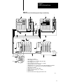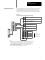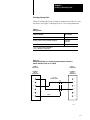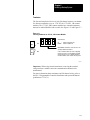
1
Chapter
1
PLC3 Programmable Controller
Backup Systems
User Manual
Important User Information
Because of the variety of uses for this product and because of the
differences between solid-state products and electromechanical products,
those responsible for applying and using this product must satisfy
themselves as to the acceptability of each application and use of this
product. For more information, refer to publication SGI-1.1 (Safety
Guidelines for the Application, Installation and Maintenance of Solid-State
Control).
The illustrations, charts, and layout examples shown in this manual are
intended solely to illustrate the text of this manual. Because of the many
variables and requirements associated with any particular installation,
Allen-Bradley Company cannot assume responsibility or liability for actual
use based upon illustrative uses and applications.
No patent liability is assumed by Allen-Bradley Company with respect to
use of information, circuits, equipment, or software described in this text.
Reproduction of the contents of this manual, in whole or in part, without
written permission of Allen-Bradley Company is prohibited.
Throughout this manual we make notes to alert you to possible injury to
people or damage to equipment under specific circumstances.
WARNING: Tells readers where people may be hurt if
procedures are not followed properly.
CAUTION: Tells readers where machinery may be damaged or
economic loss can occur if procedures are not followed
properly.
Warnings and cautions:
identify a possible trouble spot
tell what causes the trouble
give the result of improper action
tell the reader how to avoid trouble
Important: We recommend that you frequently backup your application
programs on appropriate storage media to avoid possible data loss.
PLC is a registered trademark of Allen-Bradley Company
Table of Contents
Preface . . . . . . . . . . . . . . . . . . . . . . . . . . . . . . . . . . . . . . .
P1
Manual Objectives . . . . . . . . . . . . . . . . . . . . . . . . . . . . . . . . . . .
Audience . . . . . . . . . . . . . . . . . . . . . . . . . . . . . . . . . . . . . . . . . .
What This Manual Contains . . . . . . . . . . . . . . . . . . . . . . . . . . . .
WARNINGS, CAUTIONS and Important Information . . . . . . . . . . .
Terms and Conventions . . . . . . . . . . . . . . . . . . . . . . . . . . . . . . .
Related Publications . . . . . . . . . . . . . . . . . . . . . . . . . . . . . . . . . .
P1
P1
P1
P2
P2
P3
Choosing a Backup Configuration . . . . . . . . . . . . . . . . . . .
11
Chapter Objectives . . . . . . . . . . . . . . . . . . . . . . . . . . . . . . . . . . .
Backup Concepts . . . . . . . . . . . . . . . . . . . . . . . . . . . . . . . . . . . .
Choosing a Backup Configuration . . . . . . . . . . . . . . . . . . . . . . . .
Choosing a Switchover Method . . . . . . . . . . . . . . . . . . . . . . . . . .
11
11
14
17
Installing a Backup System . . . . . . . . . . . . . . . . . . . . . . . .
21
Chapter Objectives . . . . . . . . . . . . . . . . . . . . . . . . . . . . . . . . . . .
Installing the Hardware . . . . . . . . . . . . . . . . . . . . . . . . . . . . . . . .
Power Supply Considerations . . . . . . . . . . . . . . . . . . . . . . . . . . .
Grounding Considerations . . . . . . . . . . . . . . . . . . . . . . . . . . . . .
Shielding Considerations . . . . . . . . . . . . . . . . . . . . . . . . . . . . . .
Configuring the I/O Chassis . . . . . . . . . . . . . . . . . . . . . . . . . . . . .
Configuring Scanner Modules . . . . . . . . . . . . . . . . . . . . . . . . . . .
Connecting the I/O Channel Wiring . . . . . . . . . . . . . . . . . . . . . . .
Configuring 1775MX Memory Communication Modules . . . . . . . .
21
21
26
26
26
27
28
215
224
Operating a Backup System . . . . . . . . . . . . . . . . . . . . . . .
31
Chapter Objectives . . . . . . . . . . . . . . . . . . . . . . . . . . . . . . . . . . .
Starting Up a Backup System . . . . . . . . . . . . . . . . . . . . . . . . . . .
Shutting Down a Backup System . . . . . . . . . . . . . . . . . . . . . . . . .
Restarting a Backup System . . . . . . . . . . . . . . . . . . . . . . . . . . . .
Disconnecting a Faulted Processor . . . . . . . . . . . . . . . . . . . . . . .
Restarting a Repaired Processor . . . . . . . . . . . . . . . . . . . . . . . . .
31
31
34
34
35
35
Using the 1775MX Memory Communication Module . . . . .
41
Chapter Objectives . . . . . . . . . . . . . . . . . . . . . . . . . . . . . . . . . . .
Controlling the Operation of Memory Communication Modules . . . .
Using LIST Functions for Control . . . . . . . . . . . . . . . . . . . . . . . . .
Using Message Instructions for Control . . . . . . . . . . . . . . . . . . . .
Error Codes . . . . . . . . . . . . . . . . . . . . . . . . . . . . . . . . . . . . . . . .
41
42
43
417
433
ii
Table of Contents
Programming Techniques . . . . . . . . . . . . . . . . . . . . . . . . .
51
Chapter Objectives . . . . . . . . . . . . . . . . . . . . . . . . . . . . . . . . . . .
Signal Conditioning . . . . . . . . . . . . . . . . . . . . . . . . . . . . . . . . . .
Timers and Counters at Switchover . . . . . . . . . . . . . . . . . . . . . . .
Timing Considerations at Switchover . . . . . . . . . . . . . . . . . . . . . .
Forcing I/O . . . . . . . . . . . . . . . . . . . . . . . . . . . . . . . . . . . . . . . .
Executing Block Transfers . . . . . . . . . . . . . . . . . . . . . . . . . . . . .
Restarting a Repaired Processor . . . . . . . . . . . . . . . . . . . . . . . . .
Reducing Backup Communication Overhead . . . . . . . . . . . . . . . .
Using Data Table Status Bits . . . . . . . . . . . . . . . . . . . . . . . . . . . .
Programming Considerations for Data Highway and
Data Highway Plus . . . . . . . . . . . . . . . . . . . . . . . . . . . . . . . .
Programming Considerations for Memory Communication Modules
51
51
52
53
55
55
55
56
59
516
522
Diagnosing Faults . . . . . . . . . . . . . . . . . . . . . . . . . . . . . . .
61
Chapter Objectives . . . . . . . . . . . . . . . . . . . . . . . . . . . . . . . . . . .
How the Backup System Behaves When a Major Fault Occurs . . . .
Locating a Fault . . . . . . . . . . . . . . . . . . . . . . . . . . . . . . . . . . . . .
A Logic Diagnostic Routine . . . . . . . . . . . . . . . . . . . . . . . . . . . . .
61
61
62
68
Preface
Preface
Manual Objectives
This manual shows you how to install, configure, and operate a backup
system configured with PLC-3 or PLC-3/10 processors.
In this manual we describe:
backup system concepts
procedures for installing backup systems
procedures for operating backup systems
programming techniques
fault diagnosis
Audience
Before you read this manual or attempt to use a backup system, you should
be familiar with the PLC-3 or PLC-3/10 programmable controller. Also,
you may need to be familiar with one or more optional modules used in
backup systems.
What This Manual Contains
Table A describes the contents of each chapter in this manual.
Table A
Manual Contents
If you want to read about:
Refer to Chapter:
an overview of backup concepts; description of
scanner and memory backup configurations
1 Choosing a Backup Configuration
procedures for installing a backup system; wiring
diagrams
2 Installing a Backup System
procedures for starting up, shutting down, restarting, 3 Operating a Backup System
disconnecting and restarting a repaired processor
controlling memory communication modules using
LIST commands and message instructions
4 Using the 1775MX Memory
Communication Module
signal conditioning, timing requirements, forcing I/O,
block transfers, status words, considerations when
using communication adapter and memory
communication modules
5 Programming Techniques
what happens when a fault occurs; locating faults by 6 Diagnosing Faults
using indicators and status words
P-1
Preface
WARNINGS, CAUTIONS and
Important Information
Information that is especially important to note is identified by three labels:
WARNING
CAUTION
Important
WARNING: tells you of circumstances or practices that can
lead to personal injury as well as damage to equipment.
CAUTION: tells you of circumstances or practices that can
lead to damage of equipment.
Important: provides you with information that is important for the
successful application of the PLC-3 backup system.
Terms and Conventions
Some terms used in this manual may be unfamiliar to you. We list these
terms with a brief definition of each.
Bit terminology - the states of logic bits are defined as follows:
ON = Set = 1 = high state
OFF = Reset = 0 = low state
Channel configuration - using LIST functions or message instructions to
assign specific parameters to the I/O channels on scanner modules.
Communication adapter module - refers to the 1775-KA module used in
PLC-3 and PLC-3/10 processors.
Memory communication module - refers to the 1775-MX module used in
PLC-3 processors.
Processor - refers to a PLC-3 or PLC-3/10 programmable controller
system consisting of a power supply, chassis, modules, cables, and all other
components needed to achieve an operational system.
Programming terminal - refers to an industrial terminal system, e.g.,
Allen-Bradley -T4, -T47, -T50, or -T60 terminals, or an AT-type computer
with 6200 software.
Scanner module - refers to 1775-S4A or -S5 modules used in PLC-3
processors and/or 1775-SR or -SR5 modules used in PLC-3/10 processors.
P-2
Preface
Related Publications
For more information about components used with the PLC-3 backup
system, see the publications listed in Table B.
Table B
Related Publications
Publication Title
Publication Number
PLC3 Programmable Controller Installation
and Operation Manual
17756.7.1
PLC3 Family Programmable Controller
Programming Reference Manual
17756.4.1
I/O ScannerProgrammer Interface Module
User's Manual
17756.5.2
PLC3 Communication Adapter Module
User's Manual
17756.5.1
1770T4 Industrial Terminal System
17706.5.15
PLC3 Family I/O Scanner Communication
Adapter Module User's Manual
17756.5.5
Additionally, you can use our publication index (publication SD499) as a
guide to further information about products related to the PLC-3 and
PLC-3/10 processors. Consult your local Allen-Bradley Company sales
engineer or distributor for information regarding this publication or others.
P-3
Chapter
1
Choosing a Backup Configuration
Chapter Objectives
The information in this chapter can help you:
understand backup concepts
evaluate different backup configurations
choose a switchover method
Backup Concepts
A backup system consists of two processors configured in such a way that
the backup processor will take control of outputs if the primary processor
faults. Figure 1.1 shows the basic concept of a backup system.
Figure 1.1
Basic Backup System
PRIMARY
PROCESSOR
I/O
TO/FROM I/O
BACKUP
COMMUNICATION
BACKUP
PROCESSOR
I/O
10971I
A second processor, which is identical to the first, is connected to the main
processor. During normal operation, the backup processor operates in a
listen-only mode. If the primary processor encounters a major fault, the
backup processor takes control of the outputs. This transfer of control also
can occur due to a loss of power to the primary processor or a broken
cable.
1-1
Chapter 1
Choosing a Backup Configuration
Why Use a Backup System?
Backup is useful for applications in which an unexpected shutdown is
costly or otherwise undesirable. By configuring a PLC-3 or PLC-3/10
system for backup communication, you can guard against shutdowns
caused by processor faults.
Shutdowns can also be caused by power losses or faults in equipment other
than the programmable controller. For these cases, you must take other
measures to guard against shutdown.
Important: Backup does not protect you from faults caused by
programming errors or system timeouts, because the error or timeout will
also occur in the backup processor.
Backup Terminology
Some terms you should be familiar with are:
Backup communication - communication between the primary and the
backup processors.
Backup communication channel - transfers data from the primary to the
backup processor; transfers data table values from the backup to the
primary processor; and, identifies the default processor if a cable breaks. A
backup communication channel is required for backup systems using the
scanner backup configuration.
Backup mode - a mode in which a processor performs a listen-only
function (monitors inputs without controlling outputs) while remaining
ready to take control of the outputs.
Backup processor - a programmable controller which performs a
listen-only function (monitors inputs without controlling outputs). It
remains ready to take control of outputs should a fault occur in the primary
processor.
Backup system - includes the primary and backup processor. When we use
the term processor we are referring to a processor chassis, modules, cables,
and the other components needed for operation.
Channel configuration - a procedure using the LIST feature of the
processor to assign a specific operation to one of the channels on an I/O
scanner module.
Hardware configuration - the manner in which the backup processor is
installed with the primary processor.
1-2
Chapter 1
Choosing a Backup Configuration
Primary processor - the processor that is controlling outputs. When
switchover to the backup processor occurs, the backup processor becomes
the primary processor, since now it is controlling outputs.
Stand-alone processor - a programmable controller that is not configured
for backup.
Switchover - transfer of control from the primary processor to the backup
processor.
Backup Communication
Backup communication is communication between the primary and backup
processors. Without backup communication, the backup processor receives
only input and peer-to-peer data.
Since the primary and backup processors may have started at different
times and are not synchronized, the data table values may be different in
each processor. You can reduce these differences by transferring internal
storage points via backup communication.
You can establish backup communication using:
one or more of the serial I/O channels as a backup communication
channel.
the parallel data communication of the 1775-MX memory
communication module
Data Highway or Data Highway Plus communication
1-3
Chapter 1
Choosing a Backup Configuration
Choosing a Backup
Configuration
There are two backup configurations:
scanner backup (Figure 1.2) which uses only I/O scanner modules
MX backup (Figure 1.3) which uses 1775-MX memory communication
modules
How Scanner Backup Works
Figure 1.2 shows the implementation of scanner backup. The number one
scanner module controls switchover as well as backup, peer-to-peer, and
I/O communication channels.
Figure 1.2
Scanner Backup Configuration
PRIMARY PROCESSOR
BACKUP PROCESSOR
SCANNER
MODULE #1
SCANNER
MODULE #1
B/U
TO/FROM
OTHER
PEERTOPEER
CHANNELS
CH2
TO/FROM
I/O
CH3
CH1
CH2
CH3
BACKUP CABLE
BACKUP COMMUNICATION
PEERTOPEER
COMMUNICATION
I/O COMMUNICATION
CH4
B/U
CH1
CH2
CH3
CH4
10972I
The data table of the backup processor can be updated in three ways.
The backup processor listens only to discrete real world inputs.
The input/output buffer transfers data files over the backup
communication cable. (You must program move and move file
instructions to transfer critical data table information.)
Data Highway or Data Highway Plus communication
1-4
Chapter 1
Choosing a Backup Configuration
How MX Backup Works
Figure 1.3 shows the implementation of MX backup. The scanner modules
still control I/O communication channels but the memory communication
modules handle data transfers between the primary and backup processors.
Figure 1.3
MX Backup Configuration
TO/FROM
OTHER
PEERTOPEER
CHANNELS
TO/FROM
I/O
CH1
CH2
CH3
PRIMARY PROCESSOR
BACKUP PROCESSOR
SCANNER
MODULE #1
SCANNER
MODULE #1
B/U
B/U
CH1
CH2
CH3
PEERTOPEER
COMMUNICATION
I/O COMMUNICATION
I/O COMMUNICATION
CH4
CH1
CH2
CH3
CH4
INTERCONNECT CABLE
MEMORY
COMMUNICATION
MODULE
MEMORY
COMMUNICATION
MODULE
B/U
B/U
XMTG
RCVG
BACKUP COMMUNICATION
XMTG
RCVG
10973I
1-5
Chapter 1
Choosing a Backup Configuration
Selecting Scanner or MX Backup
Table 1.A and Table 1.B summarize the attributes of scanner backup and
MX backup, respectively. Choose the backup configuration most suitable
for your application.
Table 1.A
Scanner Backup Attributes
Advantages:
Disadvantages:
No additional cost (every 1775S4A, SR, S5,
and SR5 has this feature built in).
Backup communication channel is necessary
for transferring data table and the transfer is
relatively slow (8 words per 14 milliseconds.)
External switch box may be required.
Processor restart procedure is not flexible.
Table 1.B
MX Backup Attributes
Advantages:
Disadvantages:
Data table in the backup processor is virtually
identical to the one in the primary processor.
More costly than scanner backup.
No external hardware is needed.
Highspeed data transfer from the primary to
the backup processor. (100k words per second
for continuous or 10k words per second for
onetime transfers).
Ability to transfer program data from the
primary processor to the backup processor.
Increased time required for other operations
such as program scan. This increase is
approximately 10% for file intensive programs
and approximately 15% for I/O intensive
programs. You must consider this increase
when developing your program and configuring
your system.
Extra features are available, such as memory
download, memory compare, backup status,
etc.
The only permissible switchover method is
automatic switchover with controllable
switchback.
Easily configurable through LIST.
Simple restart procedure.
1-6
Requires an extra slot in each processor
chassis.
Chapter 1
Choosing a Backup Configuration
Choosing a Switchover
Method
The three methods of switching control of outputs from the primary to the
backup processor are:
automatic switchover with no switchback
automatic switchover with controllable switchback
manual switchover
You can use any one of these methods for scanner backup, but you must
use automatic switchover with controllable switchback for MX backup.
Table 1.C lists the attributes associated with each method.
Table 1.C
Switchover Method Attributes
Switchover
Method:
Attributes:
Automatic
Switchover with
No Switchback
Backup processor automatically takes control of outputs when the primary
processor faults.
No operator intervention required at switchover.
Shutting off the primary processor initiates switchover.
Both the primary and the backup processor must be shut down and
restarted when reinstalling a repaired processor.
Not recommended for applications using multidrop modems with 1775KA
modules because the modem port is not disabled after a processor fault.
Automatic
Switchover with
Controllable
Switchback
Backup processor automatically takes control of outputs when the primary
processor faults.
No operator intervention required at switchover.
Shutting off the primary processor initiates switchover.
Either processor can be the primary" processor.
The backup processor does not have to be shut down when reinstalling a
repaired primary processor.
Not recommended for applications using multidrop modems with 1775KA
modules because the modem port is not disabled after a processor fault.
Continued on Next Page
1-7
Chapter 1
Choosing a Backup Configuration
Switchover
Method:
Attributes:
Manual
Switchover
When the primary processor faults, the system shuts down as though no
backup system were available.
Operator intervention is required at switchover.
Control of the process is lost until switchover occurs.
Quickly resume control of a process following a fault in the primary
processor.
Easy to transfer between primary and backup processor.
Manual switchovers do not guard against unexpected shutdowns as well as
automatic switchovers do.
We suggest this method for applications using multidrop modems with
1775KA modules.
1-8
Chapter
2
Installing a Backup System
Chapter Objectives
This chapter describes how to install PLC-3 and PLC-3/10 backup
systems. Specifically, it provides recommendations for:
power supplies
grounding
shielding
configuring I/O chassis
configuring scanner modules
connecting I/O channel wiring
configuring memory communication modules
Installing the Hardware
In general, the recommendations and procedures for installing a PLC-3 or
PLC-3/10 backup system closely resemble those of a stand-alone
processor. To install a backup system, do the following:
read the power supply, grounding, and shielding recommendations.
configure all I/O chassis.
configure all scanner modules.
connect and configure I/O channels.
configure 1775-MX memory communication modules (necessary only if
MX backup will be used).
This chapter describes each of these tasks. For additional detailed
information about installing PLC-3 and PLC-3/10 processors, see the
PLC-3 Programmable Controller Installation and Operation Manual
(publication 1775-6.7.1).
CAUTION: To guard against damage to equipment, make sure
that all modules in the backup processor are the same series and
revision as their counterparts in the primary processor. If not,
the backup system may not work properly.
2-1
Chapter 2
Installing a Backup System
Important: The number one scanner module (thumbwheel set to 1) in
both primary and backup processors must be a 1775-S4A or -S5 for PLC-3
based processors, or a 1775-SR or -SR5 for PLC-3/10 based processors.
Figure 2.1 on page 2-3 shows typical connections for a PLC-3 backup
system using scanner backup. Figure 2.2 on page 2-4 shows typical
connections for a PLC-3 backup system using MX backup. Figure 2.3 on
page 2-5 shows typical connections for a PLC-3/10 backup system using
scanner backup.
2-2
Chapter 2
Installing a Backup System
Figure 2.1
Connections for a PLC3 Backup System Using Scanner Backup
1
2
9
2
12
8
5
3
To Earth
Ground
10
7
5
13
2
3
11
7
4
4
6
To other
I/O Chassis
in the Channel
6
Blue
8
7
Shield
7
Clear
1.
2.
3.
4.
5.
6.
7.
8.
9.
10.
11.
12.
13.
PLC-3 Processor (Primary)
Power Supply (cat. no. 1775-P1)
1771 I/O Chassis (cat. no. 1771-A1B, -A2B, A3B, -A4B)
Power Supply (cat. no. 1771-P2)
Processor Chassis Power Cable, 6ft. (cat. no. 1775-CAP)
I/O Power Cable, 1ft. (cat. no. 1771-CE)
Twinaxial Cable (cat. no. 1770-CD) 10,000 ft. Max. Each I/O Channel at 57.6K Baud
Terminator (cat. no. 1770-XT) Connect one at each end of the I/O Channel
PLC-3 Processor (backup)
Backup Cable (cat. no. 1775-CBA, -CBB)
Backup Communication Cable (cat.no. 1770-CD)
Ground Bus Plate
Connection between Power Supply System Common studs
10391
2-3
Chapter 2
Installing a Backup System
Figure 2.2
Connections for a PLC3 Backup System Using MX Backup
1
2
9
2
12
8
5
3
To Earth
Ground
10
7
5
13
2
3
11
7
4
4
6
To other
I/O Chassis
in the Channel
6
Blue
8
7
Shield
7
Clear
1.
2.
3.
4.
5.
6.
7.
8.
9.
10.
11.
12.
13.
PLC-3 Processor (Primary)
Power Supply (cat. no. 1775-P1)
1771 I/O Chassis (cat. no. 1771-A1B, -A2B, A3B, -A4B)
Power Supply (cat. no. 1771-P2)
Processor Chassis Power Cable, 6ft. (cat. no. 1775-CAP)
I/O Power Cable, 1ft. (cat. no. 1771-CE)
Twinaxial Cable (cat. no. 1770-CD) 10,000 ft. Max. Each I/O Channel at 57.6K Baud
Terminator (cat. no. 1770-XT) Connect one at each end of the I/O Channel
PLC-3 Processor (backup)
Memory Communication Cable (cat. no. 1775-CM)
Memory Communication Cable (cat. no. 1775-CM)
Ground Bus Plate
Connection between Power Supply System Common studs
18720
2-4
Chapter 2
Installing a Backup System
Figure 2.3
Connections for a PLC3/10 Backup System Using Scanner Backup
1
7
10
6
To Earth
Ground
8
5
2
2
9
5
3
3
4
To other
I/O Chassis
in the Channel
4
Blue
6
5
Shield
5
Clear
1.
2.
3.
4.
5.
6.
7.
8.
9.
10.
PLC-3/10 Processor (Primary)
1771 I/O Chassis (cat. no. 1771-A1B, -A2B, A3B, -A4B)
Power Supply (cat. no. 1771-P2)
I/O Power Cable, 1ft. (cat. no. 1771-CE)
Twinaxial Cable (cat. no. 1770-CD) 10,000 ft. Max. Each I/O Channel at 57.6K Baud
Terminator (cat. no. 1770-XT) Connect one at each end of the I/O Channel
PLC-3/10 Processor (backup)
Backup Cable (cat. no. 1775-CBA, -CBB)
Backup Communication Cable (cat.no. 1770-CD)
Ground Bus Plate
18756
2-5
Chapter 2
Installing a Backup System
Power Supply Considerations
For a PLC-3 backup system, it is important to choose suitable power
supplies and make sure they are connected properly.
To reduce the chance of inadvertent shutdowns due to loss of power, we
recommend using two separate 1775-P1 or -P3 power supplies. Use one
power supply for the primary processor and the other power supply for the
backup processor. Further, connect each power supply to a separate source
of AC power.
Important: In backup systems, never use the processor supply for
powering an I/O chassis. A processor failure could cause the I/O to fail
also.
For detailed information about installing power supplies, refer to the
PLC-3 Programmable Controller Installation and Operation Manual
(publication 1775-6.7.1).
Grounding Considerations
All grounding requirements applicable to a stand-alone PLC-3 or
PLC-3/10 processor also apply to backup systems. In addition, you need to
do the following:
When using a 1775-P1 power supply, connect the system common studs
together on the power supplies of the primary and backup processors .
Use 1-inch braid or 8 AWG wire.
If the primary and backup processors are in separate enclosures, connect
the ground bus plates of the primary and backup processors together.
Use 1-inch braid or 8 AWG wire.
Connect the ground bus plate of either the primary or backup processor,
but not both, to earth ground.
Use star washers to assure a positive ground connection between metal
surfaces and ground lugs.
For detailed information about grounding, see Wiring and Grounding
Guidelines (publication 1770-4.1).
Shielding Considerations
2-6
Use shielded cable for I/O channel wiring as specified in the PLC-3
Programmable Controller Installation and Operation Manual (publication
1775-6.7.1) to minimize noise pickup. Also, use shielded cable for
peer-to-peer communication channels, backup communication channels,
and Data Highway/Data Highway Plus channels. We recommend using
1770-CD twinaxial cable (Belden 9463), or equivalent.
Chapter 2
Installing a Backup System
Configuring the I/O Chassis
You must configure all I/O chassis for backup mode operation. Each I/O
chassis has eight switches. Two of the switches, switches 2 and 8, are
especially important because they affect the operation of a backup system.
See Figure 2.4 for the function and location of the I/O chassis switches.
Figure 2.4
Location and Function of I/O Chassis Backplane Switches
Switch
Last State
1
OFF ON
ON
Outputs of this I/O chassis remain in their last state when
a fault is detected by this I/O adapter. 1
OFF
Outputs of this I/O chassis are turned off when a fault is
detected by this I/O adapter.
1
2
3
4
Switch
Always On
5
6
7
8
Processor Restart Lockout
2
ON
The I/O chassis can be restarted from
the processor.
OFF
The processor is locked out from
restarting the I/O chassis after a fault.
Always On
Switches
Addressing
5
6
OFF
OFF
2 - slot
ON
OFF
1 - slot 2
OFF
ON
1/2 - slot 2, 3
ON
ON
Not allowed
Pressed in
at top Closed (ON)
Pressed in at
bottom Open (OFF)
NOTES:
1. CAUTION: If you set this switch to the ON position, when a fault is detected, outputs connected to this
chassis remain in their last state to allow machine motion to continue. We recommend that you set
switch 1 to the OFF position to de - energize outputs wired to this chassis when a fault is detected.
2. The 1771 - AS adapter does not support 1 - slot or 1/2 - slot addressing. When you use this
adapter, set switches 5 and 6 to the OFF position.
3. The 1771 - ASB series A adapter does not support 1/2 - slot addressing.
16191
2-7
Chapter 2
Installing a Backup System
Setting Switch 2
The processor restart lockout switch (switch 2) must be ON so the backup
processor is capable of restarting the I/O chassis at switchover, if
necessary. If the system has more than one I/O chassis, switch 2 must be
ON in each chassis. For more detailed information about the processor
restart lockout feature, refer to the PLC-3 Programmable Controller
Installation and Operations Manual (publication 1775-6.7.1).
Setting Switch 8
The chassis I/O to backup processor switch (switch 8) must be ON so the
backup processor can receive inputs from the I/O chassis. The backup
processor will not be able to receive inputs from the I/O chassis if switch 8
is set incorrectly.
CAUTION: To guard against damage to equipment, make sure
that switch 8 on a 1771-A1B I/O chassis with starting module
group 0 is set to ON. If this switch is not ON, the backup
processor will not receive inputs from the I/O chassis.
Configuring Scanner Modules
You set up and install scanner modules whether you are configuring a
system for scanner backup or MX backup. The only difference is the cable
used between the backup connectors on the various modules.
To configure a scanner module you must:
set backup switches
select a backup cable
connect the backup cable
connect I/O channel wiring.
Setting Backup Switches
Each scanner module has four switches for selecting a switchover method
or stand-alone mode. Figure 2.5 and Figure 2.7 show the location of these
switches for the various scanner modules.
To select the backup mode, do the following:
1.
2-8
Set backup switches 1 through 4 on the number one scanner module
(thumbwheel set to 1) in both primary and backup processors for the
type of switchover desired. See Table 2.A for 1775-S4A and 1775-SR
scanners or Table 2.B for 1775-S5 and 1775-SR5 scanners.
Chapter 2
Installing a Backup System
2.
Set all backup switches on all other scanner modules, if any are
present, in both the primary and backup processors to the up position.
Figure 2.5
Location of Backup Switches for 1775S4A and 1775SR Scanner
Modules
Top Edge
of Module
18753
Figure 2.6
Setting Backup Switches on the 1775S4A and 1775SR Scanner
Modules
Not Used
(always UP)
ON
Not Used
(always UP)
ON
OFF
Switch Positions:
ON
UP
= Switch is away from board
DOWN = Switch is toward board
OFF
1
2
3
4
OFF
Set per
Table 2.A
Set per
Table 2.A
10794I
Table 2.A
Backup Switches on 1775S4A and 1775SR Scanner Modules
Switch
Switchover Method
2
4
Processor
Automatic switchover with controllable
switchback
DOWN
UP
both primary and backup
Automatic switchover with no switchback
DOWN
UP
UP
UP
primary
backup
Manual switchover
UP
DOWN
both primary and backup
Standalone mode
UP
UP
both primary and backup
2-9
Chapter 2
Installing a Backup System
Figure 2.7
Location of Backup Switches for 1775S5 and 1775SR5 Scanner
Modules
Backup Switch at
Bottom Edge of Module
Terminator Switch at
Bottom Edge of Module
18754
Figure 2.8
Setting Backup Switches on 1775S5 and 1775SR5 Scanner Modules
Not Used
(always UP)
ON
Not Used
(always UP)
ON
OFF
Switch Positions:
ON
UP
= Switch is away from board
DOWN = Switch is toward board
OFF
1
2
3
4
OFF
Set per
Table 2.B
10975I
Table 2.B
Backup Switches for 1775S5 and 1775SR5 Scanner Modules
Switch
Switchover Method
2-10
2
3
Processor
Automatic switchover with controllable
switchback
DOWN
UP
both primary and backup
Automatic switchover with no
switchback
DOWN
UP
UP
UP
primary
backup
Manual switchover
UP
DOWN
both primary and backup
Standalone mode
UP
UP
both primary and backup
Chapter 2
Installing a Backup System
Selecting a Backup Cable
Choose a backup cable for the switchover method desired. Table 2.C lists
the choices. See Figure 2.9 through Figure 2.11 for wiring information.
Table 2.C
Backup Cables
Switchover Method:
Backup Cable:
Automatic switchover with no switchback
1775CBA
Automatic switchover with controllable switchback
1775CBB1
1775CM2
Manual switchover
1775CBB
1. Use for scanner backup configuration.
2. Use for MX backup configuration.
Figure 2.9
Backup Cable Wiring for Scanner Backup with Automatic Switchover
with No Switchback (Cat. No. 1775CBA)
PRIMARY
PROCESSOR
BACKUP
PROCESSOR
SCANNER #1
BACKUP
CONNECTOR
SCANNER #1
BACKUP
CONNECTOR
1
1775CBA
BACKUP CABLE
1
2
2
3
3
4
4
5
5
6
SHIELD
6
10976I
2-11
Chapter 2
Installing a Backup System
Figure 2.10
Backup Cable Wiring for Scanner Backup with Automatic Switchover
with Controllable Switchback (Cat. No. 1775CBB)
PRIMARY
PROCESSOR
SCANNER #1
BACKUP
CONNECTOR
BACKUP
PROCESSOR
1775CBB
BACKUP CABLE
SWITCH
SCANNER #1
BACKUP
CONNECTOR
1
1
2
2
3
3
4
4
5
5
6
SHIELD
6
10977I
CAUTION: To guard against damage to equipment, make sure
that:
switch 2 closes within 8 milliseconds of switch 4
switch 3 closes within 8 milliseconds of switch 1
CAUTION: If these conditions are not satisfied when you
throw the switch to change the processor that is designated as
the primary processor to the processor currently controlling
outputs, the new primary processor may fault.
2-12
Chapter 2
Installing a Backup System
Figure 2.11
Backup Cable Wiring for Manual Switchover (Cat. No. 1775CBB)
PRIMARY
PROCESSOR
BACKUP
PROCESSOR
1775CBB
BACKUP CABLE
SCANNER #1
BACKUP
CONNECTOR
SCANNER #1
BACKUP
CONNECTOR
1
1
2
2
3
3
4
4
SWITCH
TO
SYSTEM
COMMON
5
6
5
6
10978I
Connecting the Backup Cable
Figure 2.12 shows how to connect a backup cable for the scanner backup
configuration.
Important: If you are configuring the system for MX backup instead of
scanner backup, do not connect the backup cable as shown. See the
instructions in Configuring 1775-MX Memory Communication Modules
for information about installing the interconnect cables.
To configure scanner backup, do the following:
1.
Locate the backup cable.
2.
Connect one end of the backup cable to the backup connector on the
number one scanner module (thumbwheel set to 1) in the primary
processor.
3.
Connect the other end to the backup connector on the number one
scanner module (thumbwheel set to 1) in the backup processor.
2-13
Chapter 2
Installing a Backup System
Figure 2.12
Connections for Scanner Backup
Primary Processor
Backup Processor
Backup cable (see text)
10395
2-14
Application:
Cable:
Automatic switchover with no switchback
1775CBA
Automatic switchover with controllable switchback
1775CBB
Manual switchover
1775CBB
Chapter 2
Installing a Backup System
Connecting the I/O
Channel Wiring
There are four I/O serial communication channels per scanner. Depending
on your system architecture, you can use one or more of them for:
I/O communication
Peer-to-peer communication
Backup communication
To do this, you connect I/O cables to the terminal swing arm and configure
each channel for the type of communication desired. You configure I/O
channels by using LIST.
Figure 2.13 shows how to identify the terminals on a terminal swing arm.
Figure 2.13
I/O Cables Terminate at Terminal Swing Arms
Channel
No. 3
Channel
No. 1
Line 1
Line 1
Shield
Shield
Line 2
Line 2
Line 1
Line 1
Shield
Shield
Line 2
Line 2
Channel
No. 4
Channel
No. 2
10044
Important: For 1775-S4A or -SR scanner modules used as the number
one scanner, when using I/O channel 5 to communicate with a peripheral
device, I/O channel 4 of the number one scanner module cannot be used.
Do not make any connections to I/O channel 4.
2-15
Chapter 2
Installing a Backup System
Connecting I/O Communication Channels
Figure 2.14 shows the connections when using I/O channel 1.
Figure 2.14
Connections for I/O Communication
Primary Processor
Backup Processor
Blue
Blue
Shield
Twinaxial Cable
(cat. no. 1770-CD)
Terminator
(cat. no. 1770-XT)
(Refer to page 223)
Shield
To I/O Chassis
Clear
Channel No. 1 Shown
Clear
Channel No. 1 Shown
10392
2-16
Chapter 2
Installing a Backup System
If you designate another I/O channel for use as an I/O communication
channel, replace the references to I/O channel 1 with the actual I/O channel
in the following procedure.
1.
Connect one end of a 1770-CD twinaxial cable (Belden 9463) to the
I/O channel 1 terminals on the terminal swing arm of a scanner
module in the backup processor.
2.
For 1775-S4A, -SR scanner modules, install a 1770-XT terminator to
the I/O channel 1 terminals in the backup processor as shown in
Figure 2.14. For 1775-S5 and -SR5 scanner modules, you can either
install a 1770-XT terminal or select a terminator by using the internal
switches as shown in Figure 2.17.
Important: If the internal terminator option is used, the link will be
unterminated if the swing arm is removed from the scanner.
3.
Connect the other end of the 1770-CD twinaxial cable to the I/O
channel 1 terminals on the terminal swing arm of the corresponding
scanner module in the primary processor.
4.
Connect one end of another 1770-CD twinaxial cable to the I/O
channel 1 terminals on the terminal swing arm of the scanner module
in the primary processor.
5.
Connect the other end of this cable to the designated I/O device.
6.
Repeat steps 1 through 5 for other channels used for I/O
communication.
7.
Using LIST, configure each channel for use as I/O communication.
2-17
Chapter 2
Installing a Backup System
Connecting an I/O Channel for PeertoPeer Communication
Any I/O channel can be used for peer-to-peer communication. Figure 2.15
shows the connections when using I/O channel 1.
Figure 2.15
Connecting an I/O Channel for PeertoPeer Communication
Primary Processor
Backup Processor
Terminator
(cat. no. 1770-XT)
(Refer to page 223)
Blue
Twinaxial Cable
(cat. no. 1770-CD)
Shield
Blue
Shield
To other
PLC-3 systems
Clear
Channel No. 1 Shown
Clear
Channel No. 1 Shown
10393
2-18
Chapter 2
Installing a Backup System
If you designate another I/O channel for use as a peer-to-peer
communication channel, replace the references to I/O channel 1 with the
actual I/O channel used in the following procedure.
1.
Connect one end of a cat. no. 1770-CD twinaxial cable to the I/O
channel 1 terminals on the terminal swing arm of a scanner module in
the backup processor. If this is a 1775-S4A or 1775-SR scanner
module, do not connect the shield.
For 1775-S4A and 1775-SR scanner modules, install a cat. no.
1770-XT terminator to the I/O channel 1 terminals in the backup
processor as shown in Figure 2.15. For 1775-S5 and 1775-SR5
scanner modules, you can either install a 1770-XT terminator or
select a terminator by using the internal switches as shown in
Figure 2.17 on page 2-23.
Important: If the internal terminator option is used, the link will be
unterminated if the swing arm is removed from the scanner.
2.
Connect the other end of the 1770-CD twinaxial cable to the I/O
channel 1 terminals on the terminal swing arm of the corresponding
scanner module in the primary processor. Connect the shield.
3.
Connect one end of another 1770-CD twinaxial cable to the I/O
channel 1 terminals on the terminal swing arm of the scanner module
in the primary processor. Connect the shield.
4.
Connect the other end of this 1770-CD twinaxial cable to the
designated peer-to-peer channel in another processor. If this is a
1775-S4A or 1775-SR scanner module, do not connect the shield.
5.
Connect one end of another 1770-CD twinaxial cable to the I/O
channel 1 terminals on the terminal swing arm of this scanner
module. Connect the shield.
6.
Connect the other end of this 1770-CD twinaxial cable to the
designated peer-to-peer channel in another processor. If this is a
1775-S4A or 1775-SR scanner module, do not connect the shield.
7.
Repeat steps 5 and 6 for up to 6 slaves and 1 master.
2-19
Chapter 2
Installing a Backup System
8.
If the last scanner is a 1775-S4A or 1775-SR scanner module, install
a 1770-XT terminator to the I/O channel 1 terminals as shown in
Figure 2.15. For 1775-S5 and 1775-SR5 scanner modules, you can
either install a 1770-XT terminator or select a terminator by using the
internal switches as shown in Figure 2.17 on page 2-23.
9.
Using the LIST function, configure I/O channel 1 in the backup
processor for peer-to-peer communication. Use the same peer-to-peer
station number as the primary processor. If the primary processor is a
master, configure the backup processor as a master. If the primary
processor is a slave, configure the backup processor as a slave.
Important: The master number must be different from all slave numbers
on the link. The master number and all slave numbers must be unique and
selected from numbers 81 through 89.
As shown in the above procedure, the twinaxial cable shield is always
connected on 1775-S5 or 1775-SR5 scanner modules but alternately
connected between 1775-S4A or 1775-SR scanner modules.
2-20
Chapter 2
Installing a Backup System
Connecting an I/O Channel for Backup Communication
Any I/O channel can be used for backup communication. Figure 2.16
shows the connections when using I/O channel 1.
Figure 2.16
Connecting an I/O Channel for Backup Communication
Primary Processor
Backup Processor
Terminator
(cat. no. 1770-XT)
Blue
Blue
Twinaxial Cable (cat. no. 1770-CD)
Shield
(Refer to page 223)
Shield
Terminator
(cat. no. 1770-XT)
Clear
Channel No. 1 Shown
(Refer to page 223)
Clear
Channel No. 1 Shown
10394
2-21
Chapter 2
Installing a Backup System
If you designate another I/O channel for use as a backup communication
channel, replace the references to I/O channel 1 with the actual I/O channel
used in the following procedure.
1.
Connect one end of a 1770-CD twinaxial cable to the I/O channel 1
terminals on the terminal swing arm of a scanner module in the
backup processor.
2.
For 1775-S4A, -SR scanner modules, install a 1770-XT terminator to
the I/O channel 1 terminals in the backup processor as shown in
Figure 2.16. For 1775-S5 and -SR5 scanner modules, select a
terminator by using the internal switches as shown in Figure 2.17.
3.
Connect the other end of the 1770-CD twinaxial cable to the I/O
channel 1 terminals on the terminal swing arm of the corresponding
scanner module in the primary processor.
4.
For 1775-S4A, -SR scanner modules, install a 1770-XT terminator to
the I/O channel 1 terminals in the primary processor as shown in
Figure 2.16. For 1775-S5 and -SR5 scanner modules, select a
terminator by using the internal switches as shown in Figure 2.17.
5.
Using the LIST function, configure I/O channel 1 for backup
communication in both the primary and backup processors.
Important: Use numbers 81 through 89 for the resident and partner
numbers.
CAUTION: To guard against damage to equipment, make sure
that you configure each channel in the backup system with the
same resident and partner numbers, when using multiple backup
communication channels. If you use a different resident or
partner number on different channels of the same processor,
both processors may shut down if the backup cable breaks.
2-22
Chapter 2
Installing a Backup System
Terminators
The first and last physical device of each I/O channel requires a terminator.
Use discrete terminators (cat. no. 1770-XT) for 1775-S4A, -SR scanner
modules. The 1775-S5, -SR5 scanner modules have internal terminators
that can be enabled/disabled with a switch. See Figure 2.17 and Figure 2.7.
Figure 2.17
Selecting Terminators on 1775S5, SR5 Scanner Modules
Switch Positions:
ON
ON
OFF
ON
OFF
1
2
3
4
UP
= Switch is away from board
DOWN = Switch is toward board
When DOWN, a terminator is connected on the corre
sponding communication channel.
OFF
Connect a terminator when the scanner is physically
the first or last device on a Data Highway, Data High
way Plus, I/O, peertopeer, or backup communica
tions link; otherwise, set the switch to the UP position.
10979I
Important: When using internal terminators, removing the terminal
swing arm from a module causes the communication channels to be
unterminated.
For more information about terminators and I/O channel wiring, refer to
the PLC-3 Programmable Controller Installation and Operation Manual
(publication 1775-6.7.1).
2-23
Chapter 2
Installing a Backup System
Configuring 1775MX Memory
Communication Modules
To implement MX backup you need two 1775-MX memory
communication modules, one for the primary processor and another for the
backup processor, and one 1775-CM memory communication cable
assembly. The cable assembly consists of four cables. Two of them are
interconnect cables (3 feet long) that eliminate the need for a 1775-CBA or
1775-CBB backup cable. The other two cables are communication cables
(30 feet long).
Figure 2.18 shows the connections required for MX backup.
Figure 2.18
Connections for MX Backup
RCVG
Primary Processor
RCVG
Backup Processor
Interconnect
Cable
XMTG
Memory Communication Cable Assembly (cat. no. 1775-CM)
XMTG
12187
2-24
Chapter 2
Installing a Backup System
To configure MX backup, do the following:
1.
Insert one memory communication module in the primary processor
and one in the backup processor. A memory communication module
can occupy any slot in a PLC-3 processor chassis; however, to obtain
the best system performance in multi-chassis systems, you should
place the memory communication module in the same chassis as the
memory modules.
2.
Connect the XMTG end of a 1775-CM cable to the XMTG connector
on the memory communication module in the backup processor.
3.
Connect the RCVG end of this cable to the RCVG connector on the
memory communication module in the primary processor.
4.
Connect the RCVG end of the other 1775-CM cable to the RCVG
connector on the memory communication module in the backup
processor.
5.
Connect the XMTG end of this cable to the XMTG connector on the
memory communication module in the primary processor.
6.
Connect one end of a 1775-CM interconnect cable to the backup
connector on the number one scanner module in the primary
processor.
7.
Connect the other end of this cable to the backup connector on the
memory communication module in the primary processor.
8.
Connect one end of the other 1775-CM interconnect cable to the
backup connector on the number one scanner module in the backup
processor.
9.
Connect the other end of this cable to the backup connector on the
memory communication module in the backup processor.
10. Set the option switches on the number one scanner modules in both
the primary and backup processor for automatic switchover with
controllable switchback. See Table 2.A on page 2-9 or Table 2.B on
page 2-10.
CAUTION: To guard against damage to equipment, support
1775-CM cables so the weight of the cable does not cause stress
at the connectors. If you don’t support the cables, the wires may
break.
2-25
Chapter
3
Operating a Backup System
Chapter Objectives
This chapter describes how to operate a backup system. It recommends
procedures for:
starting up a backup system
shutting down a backup system
restarting a backup system
disconnecting a faulted processor
restarting a repaired processor.
CAUTION: To guard against damage to equipment, make sure
you follow the startup procedure recommended for your backup
system configuration. If you use the wrong procedure, the
backup processor could be configured improperly, or the
primary processor could be prevented from regaining control of
outputs.
Starting Up
a Backup System
To start up a backup system for the first time, find the appropriate startup
method for your backup configuration in Table 3.A, then follow that
procedure.
Table 3.A
Startup Procedure Selection
If You Have This Backup Configuration:
Use This
Startup Procedure:
Page
Scanner backup
Method 1
32
Method 2
33
MX backup if programs in the primary and backup
processors are different
MX backup if programs in the primary and backup
processor are identical
3-1
Chapter 3
Operating a Backup System
Startup Procedure Method 1
1.
Turn off both the primary and backup processors, if they are not
already off.
2.
Turn on the backup processor.
3.
Select program load mode in the backup processor.
4.
Load the program into the backup processor.
5.
Select automatic configuration to configure the I/O channels in the
backup processor.
6.
Manually configure peer-to-peer or backup communication channels,
if any are used. If you need additional information to complete this
step, refer to the PLC-3 Family Programmable Controller
Programming Reference Manual (publication 1775-6.4.1).
7.
Turn off the backup processor.
8.
Turn on the primary processor.
9.
Select program load mode in the primary processor.
10. Load the program into the primary processor.
11. Select automatic configuration to configure the I/O channels in the
primary processor.
12. Manually configure peer-to-peer or backup communication channels,
if any are used. If you need additional information to complete this
step, refer to the PLC-3 Family Programmable Controller
Programming Reference Manual (publication 1775-6.4.1).
13. Turn on the backup processor.
14. If a series A, revision C (or earlier) communication adapter module
(1775-KA) is in the backup processor, change the Data Highway
station number now. If you need additional information to complete
this step, refer to the section Programming Considerations for Data
Highway and Data Highway Plus on page 5-13, or the PLC-3
Communication Adapter Module User’s Manual (publication
1775-6.5.2).
15. Select run mode in the backup processor.
16. Select run mode in the primary processor.
3-2
Chapter 3
Operating a Backup System
Startup Procedure Method 2
1.
Turn off both the primary and backup processors, if they are not
already off.
2.
Turn on the primary processor.
Important: Whichever processor you turn on first is designated as the
primary processor; the other is designated as the backup processor.
3.
Select program load mode in the primary processor.
4.
Load the program into the primary processor.
5.
Using the LIST functions in the primary processor, configure all
modules in the primary processor.
6.
Turn on the backup processor.
7.
Select program load mode in the backup processor.
8.
Using the LIST function, perform a memory download.
Important: If the primary processor was in run mode when you executed
memory download, the backup processor will be in run mode when the
download is completed.
9.
If a series A, revision C (or earlier) communication adapter module
(1775-KA) is in the backup processor, change the Data Highway
station number now. If you need additional information to complete
this step, refer to the PLC-3 Communication Adapter Module User’s
Manual (publication 1775-6.5.1).
10. Select run mode in the backup processor.
11. Select run mode in the primary processor.
Important: You can write the ladder program so the primary processor
automatically performs a memory download when it enters the run mode.
Doing this would allow you to skip step 8 in the startup procedure. The
example rungs in Figure 3.1 show how to program the download.
3-3
Chapter 3
Operating a Backup System
Figure 3.1
Example Rung for Performing Memory Download at Startup
Inputs
B1:0
S0:3
EN
00
17
Shutting Down
a Backup System
Restarting
a Backup System
3-4
MSG
Message
Control
Channel
Download
#B0:0
E2.14.1
05
DN
ER
To shut down a backup system, do the following:
1.
Select program load mode in the primary processor.
2.
Select program load mode in the backup processor.
3.
Turn off the backup processor.
4.
Turn off the primary processor.
If you followed the shutdown procedure previously described, you can
restart the backup system by doing the following:
1.
Turn on the primary processor.
2.
Turn on the backup processor.
3.
Select run mode in the backup processor.
4.
Select run mode in the primary processor.
Chapter 3
Operating a Backup System
Disconnecting
a Faulted Processor
To troubleshoot and/or repair a faulted processor, you may have to
disconnect it.
To disconnect a faulted processor, do the following:
1.
Turn off the faulted processor.
2.
Disconnect the following cables:
3.
a.
For the scanner backup configuration, disconnect the backup
cable from the number one scanner module in the faulted
processor.
b.
For the MX backup configuration, disconnect the
communication cables from the RCVG and XMTG connectors
on the memory communication module in the faulted processor.
Remove the terminal swing arms from all scanner modules in the
faulted processor.
CAUTION: To guard against damage to equipment, be careful
not to short any of the field wiring while removing terminal
swing arms. If shorts occur in field wiring, equipment may be
damaged.
Restarting
a Repaired Processor
The procedure for restarting a repaired processor depends on the backup
system configuration and switchover method used.
To restart a repaired processor, find the appropriate restarting method to
use in Table 3.B, then follow that procedure.
Table 3.B
Restarting Procedure Selection
Use This
Restarting Procedure:
Page
Scanner backup if using automatic switchover with no
switchback
Method 1
36
Scanner backup if using automatic switchover with
controllable switchback;
Method 2
37
Method 3
37
If You Have This Backup Configuration:
MX backup
Scanner backup if using manual switchover
3-5
Chapter 3
Operating a Backup System
Restart Procedure Method 1
1.
Turn off both processors, if they are not already off.
2.
Reconnect the backup cable to the number one scanner module in the
repaired processor.
3.
Reconnect the terminal swing arms to all scanner modules in the
repaired processor.
4.
Turn on the backup processor.
5.
Select program load mode in the backup processor.
6.
Verify that channel configurations, values in data tables, and user
program are correct in the backup processor. If there are any incorrect
entries, correct them before proceeding.
7.
Turn off the backup processor.
8.
Turn on the primary processor.
9.
Select program load mode in the primary processor.
10. Verify that channel configurations, values in data tables, and user
program are correct in the primary processor. If there are any
incorrect entries, correct them before proceeding.
11. Turn on the backup processor.
12. Select run mode in the backup processor.
13. Select run mode in the primary processor.
3-6
Chapter 3
Operating a Backup System
Restart Procedure Method 2
1.
For the scanner backup configuration, place the switch, located in the
backup cable, so that the processor currently controlling outputs is the
primary processor.
2.
Reconnect the following cables:
a.
For scanner backup configuration, reconnect the backup cable to
the number one scanner module in the repaired processor.
b.
For the MX backup configuration, reconnect the communication
cables to the RCVG and XMTG connectors on the memory
communication module in the faulted processor.
3.
Reconnect the terminal swing arms to all scanner modules in the
repaired processor.
4.
Turn on the repaired processor.
5.
Check the configuration of each I/O channel, values in the data
tables, and the program in the repaired processor. If there are any
incorrect entries, correct them before proceeding. Manually
reconfigure the repaired processor, if necessary.
6.
Select run mode in the repaired processor.
Restart Procedure Method 3
1.
Reconnect the backup cable to the number one scanner in the repaired
processor.
2.
Reconnect the terminal swing arms to all scanner modules in the
repaired processor.
3.
Turn on the repaired processor.
4.
Check the configuration of each I/O channel, values in the data
tables, and the program in the repaired processor. If there are any
incorrect entries, correct them before proceeding. Manually
reconfigure the repaired processor, if necessary.
5.
Select run mode in the repaired processor.
3-7
Chapter
4
Using the 1775MX
Memory Communication Module
Chapter Objectives
This chapter describes how to use 1775-MX memory communication
modules. Depending on your application, you can program the memory
communication module to:
transfer data from the primary processor to the backup processor to
ensure that the data table in the backup processor matches that in the
primary processor.
transfer data from the backup processor to the primary processor to
provide data or status back to the primary.
download memory from the primary processor to the backup processor
to initialize the backup processor with the same data and configuration
as the primary processor.
control on-line editing capability to prevent the primary processor or
backup processor from being programmed independently.
compare the ladder programs in the primary and backup processors to
ensure that all or part of the programs are identical.
voluntarily transfer control to the backup processor. For example, you
could switch over to the backup processor when performing
maintenance on the primary processor.
disable the backup processor from assuming control of the outputs after
switchover. For example, when on-line editing is occurring in the
primary processor but the changes have not yet been sent to the backup
processor.
4-1
Chapter 4
Using the 1775MX
Memory Communication Module
Controlling the Operation
of Memory Communication
Modules
As shown in Table 4.A, you can control operation of memory
communication modules by using:
LIST functions (see page 4-3).
message (MSG) instructions (see page 4-16).
Typically, you use LIST functions during the development of your
application. This approach lets you select and deselect options manually.
In addition to providing additional selections, you can use message
instructions to automate memory communication module setup once you
are sure of the application. By inserting message instructions into the
ladder program, the memory communication module can be configured
automatically when powering up in the run mode or whenever the system
changes from program mode to run mode.
Table 4.A
LIST Functions and MSG Instructions
By Using:
You can:
4-2
LIST Function
MSG Instruction
transfer the contents of the data table from the
primary to the backup processor continuously
Yes
Yes
transfer the contents of selected files from the
primary to the backup processor continuously
Yes
Yes
transfer the contents of the data table from the
primary to the backup processor one time
No
Yes
transfer the contents of selected files from the
primary to the backup processor one time
No
Yes
stop further continuous transfers once the transfer
in progress completes
Yes
Yes
download memory from the primary to the backup
processor
Yes
Yes
control online editing capability for a
programmable terminal
Yes
Yes
compare the ladder program in the backup
processor with the one in the primary processor
continuously
Yes
Yes
transfer control to the backup processor
No
Yes
inhibit the backup processor from taking control of
outputs when the primary processor faults
No
Yes
transfer backup processor data to the primary
processor
Yes
Yes
Chapter 4
Using the 1775MX
Memory Communication Module
The following sections describe how to control memory communication
modules by using LIST functions and message instructions.
Using LIST Functions
for Control
The LIST functions for memory communication modules follow the same
convention as other modules in a PLC-3 system.
Important: Concerning the operation of LIST functions, note the
following points:
If the primary processor faults, switchover occurs and the backup
processor takes control of outputs. The backup processor assumes that
LIST is active unless it encounters a program control command to
redirect control to the ladder program. When the primary processor is
repaired and restarted, it becomes the “backup” processor, and the
memory communication module resumes operation.
If the backup processor faults, all data transfers in progress stop until the
backup processor is repaired and restarted. Once the backup processor is
active again, the memory communication module resumes operation.
You can view the status of a memory communication module by making a
series of selections in the LIST menu. You can view the status of a memory
communication module from either the primary processor or the backup
processor Figure 4.1. If you make selections from the backup processor,
however, they have no effect on the operation of the memory
communication module until the backup processor takes control of outputs.
The only exception is the backup to primary data transfer function; it can
be accessed through the backup processor.
Important: In this manual, the term MCM refers to the memory
communication module not to the PLC-3 high-speed interface and
diagnostic software (cat. no. 1775-MCM).
4-3
Chapter 4
Using the 1775MX
Memory Communication Module
Figure 4.1
LIST Menu for Primary and Backup Processor
SYSTEM MODE
1
TEST MONITOR
2 * RUN MONITOR
3
PROGRAM LOAD
4 * REMOTE ENABLE
5
SYSTEM STATUS
6
MODULE STATUS
ENTER NEXT >
MODULES
1 01 1775-ME8 A/A
2 01 1775-L3 A/E
3 01 1775-S5 A/G
4 01 1775-MX A/C
ENTER NEXT >
MCM OPERATION
CHASSIS 00 SLOT 06
SYSTEM ID. 03
LIST CONTROL
1
INACTIVE
2 * FILE TRANSFER
3
DATA TABLE XFER
4
MEMORY DOWNLOAD
5
LOCK SYSTEM
6 * UNLOCK SYSTEM
7
ENABLE PROG COMP
8 * DISABLE PROG COMP
9
FILE SELECTION
10 PROG COMP LIMITS
11 BACKUP TO PRIMARY DATA TRANSFER
ENTER NEXT >
THIS FEATURE CAN ONLY BE ENABLED/DISABLED WHEN SYSTEM IS IN PROGRAM MODE. THIS FEATURE MUST BE CONFIGURED IDENTICALLY IN BOTH THE PRIMARY AND BACKUP MX
MODULES.
ENTER E TO ENABLE THIS FEATURE OR D TO DISABLE IT.
PROG COMP LIMITS
0=COMP DISABLED
MAIN
00004
SUBROUTINE
00003
FAULT
00000
FILE SELECTIONS
1 O0
2 I0
3 N23
4 D2
5 T0
6 C0
ENTER NEXT >
10980I
The MCM OPERATION menu shows you three things:
the source of control functions
selections made in LIST
present operational status of the memory communication module
Chassis and slot information appear directly beneath the title of the menu.
A system identification number, which is derived from the chassis and slot
numbers of scanner number one, is also shown.
4-4
Chapter 4
Using the 1775MX
Memory Communication Module
As shown in Table 4.B, a heading, which appears directly beneath the
system identification, identifies the current source of control commands for
the memory communication module.
Table 4.B
Menu Headings
This heading:
Tells you that:
LIST CONTROL
operation of the memory communication module is being
controlled by selections made in LIST
PROGRAM CONTROL
operation of the memory communication module is being
controlled by message instructions in the ladder program
BACKUP
you are viewing LIST selections for the memory communication
module in the backup processor. These selections have no affect
on system operation (except for the Backup to Primary Data
Transfer function) as long as the primary processor is controlling
outputs.
Important: At switchover, the backup processor takes control of the
outputs and LIST selections in the backup processor take effect
immediately.
As shown in Table 4.C, symbols, which appear to the left of the entries on
the menu, identify the LIST selections that have been made and the current
operational status of the memory communication module.
Table 4.C
Menu Symbols
This symbol:
Means that:
*
the command has been selected in LIST and is active.
L
the command has been selected in LIST and would be active if
module operation were under LIST control. LIST selections could
also be inactive if the primary processor is in program load mode.
the command has not been selected in LIST, but is active. This
could occur for the following reasons:
A
operation of the module is being controlled by the
ladder program
the module cannot execute the LIST function selected
the processor is in program load mode
the MCM OPERATION menu displayed is for the
memory communication module in the backup
processor
Note that there is an A entry for every L.
4-5
Chapter 4
Using the 1775MX
Memory Communication Module
The MCM OPERATION menu contains an entry for each LIST function
listed in Table 4.D. These functions are a subset of those available when
using message instructions.
Table 4.D
LIST Functions
Command
Description
INACTIVE
The memory communication module stops both continuous
data transfers and continuous file transfers to the backup
processor.
FILE TRANSFER
The memory communication module transfers the selected
files from the primary to the backup processor continuously.
FILE SELECTION
Lets you select up to 16 files for use with the file transfer
function.
DATA TABLE XFER
The memory communication module continuously transfers
the entire data table, except the data table status section,
from the primary to the backup processor.
MEMORY DOWNLOAD
The memory communication module stops any data transfer
in progress and transfers the entire contents of PLC3
memory from the primary to the backup processor.
LOCK SYSTEM
The memory communication module has the edit resource
for both the primary and backup processors. This protects
the ladder program in the current context from being edited
while in the run or test mode.
UNLOCK SYSTEM
The memory communication module releases the edit
resource for both the primary and backup processors.
ENABLE PROG COMP
The memory communication module compares the ladder
diagram program in the backup processor with the one in the
primary processor on a wordbyword basis.
DISABLE PROG COMP
The memory communication module prevents the execution
of the program compare function.
PROG COMP LIMITS
Lets you select specific sections of the ladder program to be
compared when ENABLE PROG COMP has been
selected.
BACKUP TO PRIMARY
DATA TRANSFER
Lets you transfer up to 16 words from the backup to the
primary processor.
The following sections describe each LIST command in detail.
4-6
Chapter 4
Using the 1775MX
Memory Communication Module
Inactive Command
The INACTIVE command lets you discontinue continuous data table and
file transfers. As long as the selection INACTIVE is active, the memory
communication module inhibits data and file transfers between the primary
processor and the backup processor.
If a data or file transfer was in progress when you selected the INACTIVE
function, it will become effective on completion of the transfer in progress.
Then, all subsequent data and file transfers will be inhibited.
File Transfer Command
The FILE TRANSFER command lets you transfer a group of selected files
from the primary to the backup processor. You can specify from 1 to 16
files by using the file selection function.
When the selection FILE TRANSFER is active, the memory
communication module transfers the selected files from the primary to the
backup processor continuously. If the list of files contains a file that does
not exist in the primary processor, the memory communication module:
displays the message FILE LIST ERROR on the PLC-3 front panel or
on the programming terminal
proceeds to the next legitimate file in the list.
For the file transfer function to work properly, the primary processor must
be in run mode or test mode. File transfer will stop if you switch the
primary processor to program mode. When you switch the primary
processor out of program mode, file transfer will become active again as
long as the selection FILE TRANSFER is still active in LIST.
4-7
Chapter 4
Using the 1775MX
Memory Communication Module
File Selection Command
To specify a group of files, select the entry FILE SELECTION in the
MCM OPERATION menu. The files currently in the list are displayed,
followed by the prompt FILE SELECTION ENTER NEXT>.
You select up to 16 files, one at a time, by entering information using the
following syntax:
e/sf [ENTER]
where:
e is the entry number (1 to 16)
s is the data table section specifier (Table 4.E)
f is the file number
Table 4.E
Data Table Section Specifiers
Data Table Section
Specifier
Output Image
O
Input Image
I
Timer
T
Counter
C
Integer
N
Floating Point
F
Decimal (BCD)
D
Binary
B
ASCII
A
High Order Integer
H
Pointers
P
Status
S
Important: You must use the slash (/) as the delimiter separating the entry
number from the data table section specifier. For example, to add decimal
file 2 to the fourth position in the list, type:
4/D2 [ENTER]
4-8
Chapter 4
Using the 1775MX
Memory Communication Module
Important: Timers and counters cannot be separated into control, preset,
and accumulated value for the purpose of file transfers. In addition,
pointers cannot be separated into section, file, and word. Therefore, no file
number is necessary (although you can specify file 0). For example, to add
the timer section to the fifth position in the list, the counter section to the
sixth position, and the pointer section to the seventh position in the list,
type:
5/T
6/C
7/P
or 5/T0 [ENTER]
or 6/C0 [ENTER]
or 7/P0 [ENTER]
Important: Changes to the file list do not become effective until you
reselect the FILE TRANSFER function. This helps prevent deleting a file
by mistake. To delete a file, use the following procedure:
1.
To delete the third file, for example, type:
3 [ENTER]
2.
Move back to the MCM OPERATION menu by pressing:
[ENTER]
3.
To make the change effective, type:
2 [ENTER]
Now, the third file on the file list has been deleted.
CAUTION: To guard against damage to equipment, make sure
there is sufficient memory available in the backup processor to
accommodate the files when the memory communication
module (1775-MX) executes a file transfer. If not enough
memory is available, the backup processor will shut down.
4-9
Chapter 4
Using the 1775MX
Memory Communication Module
Data Table Transfer Command
The DATA TABLE XFER command lets you transfer all of the data table
sections except the status section (section 13), from the primary processor
to the backup processor continuously. The memory communication module
transfers all undefined sections, i.e., 14, 15, and so on, as well.
The primary processor must be in run mode or test mode for transfers to
occur. If you switch the primary processor to program mode, data table
transfer becomes inactive.
The memory communication module forces the data table in the backup
processor to be identical to the one in the primary processor. Thus,
deletions as well as creations may take place in the backup processor.
Further, if a section of the data table exists in the backup processor but not
in the primary processor, that section will be deleted in the backup
processor.
LIST commands INACTIVE, FILE TRANSFER, and DATA TABLE
XFER are mutually exclusive, i.e., only one may be used at a time.
CAUTION: To guard against damage to equipment, make sure
there is sufficient memory available in the backup processor to
accommodate the data when the memory communication
module (1775-MX) executes a data table transfer. If not enough
memory is available, the backup processor will shut down.
4-10
Chapter 4
Using the 1775MX
Memory Communication Module
Memory Download Command
The MEMORY DOWNLOAD command lets you transfer the entire
contents of the PLC-3 memory from the primary to the backup processor.
This transfer occurs once each time you request it, and has a higher priority
than the data transfer function.
The backup processor cannot take control of outputs if the primary
processor faults during the download. After the transfer is completed, the
LIST menu is redisplayed and the memory communication module
resumes operation.
Important: A memory download will not occur if:
- the backup processor has insufficient memory to accommodate the
memory contents of the primary processor. Should this occur, the memory
communication module will abort the memory download and resume
operation.
- an error occurs during download. In this case, the memory
communication module aborts the memory download and the backup
processor shuts down.
- the keyswitch on the primary processor is in the MEMORY PROTECT
ON position. This causes the primary processor to display an error message
unless the ignore keyswitch option is enabled on privilege 72.
Important: If you are using a series A, revision C (or earlier)
communication adapter module (1775-KA) in the backup processor, you
must change its Data Highway station number after performing a memory
download.
Lock System Command
The LOCK SYSTEM command lets you protect the ladder program in the
current context of both the primary and backup system from being edited
by a programming terminal. This protection remains in effect until you
unlock the processor or place it in program mode.
For this command to function properly, the primary processor must be in
run mode or test mode. If you switch the primary processor to program
mode, the memory communication module unlocks both the primary and
backup processors.
4-11
Chapter 4
Using the 1775MX
Memory Communication Module
When you select the LOCK SYSTEM command, the memory
communication module attempts to acquire the edit resource for both the
primary and backup processors. The edit resource is defined as the ability
of a programming terminal to create and/or edit the ladder program in the
current context and manipulate the data table. If a ladder program is
already being edited with a programming terminal, the memory
communication module cannot acquire the edit resource until the editing
session is terminated.
Even though a PLC-3 backup system is locked, you can still:
create and delete PLC-3 memory sections
edit contexts other than the current context
Important: When the PLC-3 backup system is locked, a programming
terminal cannot edit the ladder program in the current context. Other
intelligent devices must honor the edit resource.
Important: The PLC-3 backup system is not considered locked unless the
edit resource is acquired for both processors.
You can check the status of each processor by looking at file 4, word 0 of
the status section. For further information about interpreting status words
refer to Using Data Table Status Bits in chapter 5.
Unlock System Command
The UNLOCK SYSTEM command lets you release the edit resource for
both the primary and backup processors, thus allowing you to edit the
program in the current context with a programming terminal.
4-12
Chapter 4
Using the 1775MX
Memory Communication Module
Enable Program Compare Command
The ENABLE PROG COMP command lets you compare the ladder
program in the backup processor with the one in the primary processor on
a word-by-word basis. This function works in conjunction with the
program compare limits selections. See Table 4.F.
Table 4.F
Program Compare
If the memory communication module:
Then:
completes the program compare without
error
bit 13 is set in file 4, word 0 of the status section.
(You must reset this bit.) The memory
communication module continues the comparison
until a miscompare occurs.
encounters a miscompare, LIST will show:
bit 12 is set in file 4, word 0 of the status section;
the address of the rung containing the
miscomparison is put into file 4, words 1 and 2;
and bit 14 is reset in file 4, word 0.
L
A
Enable Program Compare
Disable Program Compare
To continue the comparison, you must reset the
status bit (bit 12 in file 4 word 0) and reselect
ENABLE PROG COMP
For a further description of status bits, see Using
Data Table Status Bits in chapter 5 of this manual.
For a program comparison to occur, the primary processor must be in run
mode or test mode. If you switch the primary processor to program mode,
the program comparison function becomes inactive. When you switch the
primary processor out of program mode, program comparison will become
active again if the selection ENABLE PROG COMP is still active in LIST.
Important: Some data appearing in the ladder diagram is actually
contained in the data table. If you alter a ladder diagram (in either the
primary or the backup processor) in such a way that the information in the
data table changes but the information in the program section remains
unchanged, then the program comparison function will not detect a
miscomparison. This may happen when using the following instructions:
-
message send
block transfer
file instructions
bit shifts
-
diagnostic detect
timers
counters
first-in-first-out (FIFO)
4-13
Chapter 4
Using the 1775MX
Memory Communication Module
Disable Program Compare Command
The DISABLE PROG COMP command lets you disable the program
comparison function. When this command is active, the memory
communication module resets the program comparison status bit.
Program Compare Limits Command
The PROG COMP LIMITS command lets you select specific sections of
the ladder program to be compared when ENABLE PROG COMP has
been selected.
This function works in conjunction with the enable program compare
function. For the command to operate properly, you must select the limit
before you select ENABLE PROG COMP.
When you select PROG COMP LIMITS, the PROG COMP LIMITS menu
appears. The menu shows the current value of limits used for the program
compare function. The first time you select this function, all limits are set
to zero. The display will show the values of limits upon subsequent use.
Legitimate values for limits range from 1 to 32,767.
PROG COMP LIMITS
0=COMP DISABLED
MAIN
00000
SUBROUTINE
00000
FAULT
00000
ENTER NEXT >
Each limit has a corresponding label comment number in the ladder
program. If you need further assistance with label comment numbers, refer
to the PLC-3 Programmable Controller Programming Manual (publication
1775-6.4.1) for detailed information.
When the enable program compare selection is active, the memory
communication module compares each section of the ladder program from
the first rung through the specified rung. As shown in LIST by 0 =
COMPARE DISABLED, if you set the limit for a particular section at
zero, the module does not compare that section. If the memory
communication module cannot find the label comment number for a
section, it will compare that entire section of the ladder program.
4-14
Chapter 4
Using the 1775MX
Memory Communication Module
To enter the program compare limits, do the following:
1.
Select the command PROG COMP LIMITS from the MCM
OPERATION menu by typing:
10 [ENTER]
2.
Enter the program limits into the PROG COMP LIMITS menu using
the following syntax:
m/s/f
where:
3.
m is the limit for the main program section
s is the limit for the subroutine program section
f is the limit for the fault program section
To begin the program compare function, select the command
ENABLE PROG COMP from the MCM OPERATION menu by
typing:
7 [ENTER]
Important: If a limit is modified while a program comparison is in
progress, the new value will not be used until you select the command
ENABLE PROG COMP again.
4-15
Chapter 4
Using the 1775MX
Memory Communication Module
Backup to Primary Data Transfer Command
The BACKUP TO PRIMARY DATA TRANSFER command lets you
enable the backup to primary data transfer function. When enabling or
disabling this feature, the processor must be in program mode.
When you enable BACKUP TO PRIMARY DATA TRANSFER, the
backup processor transmits up to sixteen words from the memory
communication module’s data table status section (beginning at S4:4) into
corresponding data table locations of the memory communication module
in the primary processor.
The following conditions must exist for the backup to primary data transfer
to occur:
Both the primary and backup memory communication modules must be
revision A/C or later.
The backup to primary data transfer function must be selected in both
the primary and backup processors via LIST function or message
command.
The number of words to be transferred must be created beginning with
S4:4. Note that there is no requirement to have the files the same length.
However, the backup processor will send only the number of words
contained in the smaller of the two backup and primary files.
This transfer occurs only in conjunction with a data table transfer or a
file transfer from the primary to the backup.
4-16
Chapter 4
Using the 1775MX
Memory Communication Module
Using Message Instructions
for Control
Operation of a memory communication module using message (MSG)
instructions follows the same convention as other modules in a PLC-3
system. The memory communication module has additional functions,
however, that let you enable and disable operation of memory
communication modules from the ladder program.
Table 4.G lists the commands available for use in message instructions. All
of the functions available in LIST are also available in message
instructions. In addition, there are four commands - TRANSFER DATA,
TRANSFER $<file list>, DISABLE OUTPUTS, PROGRAM CONTROL
- available in message instructions that are not available when using LIST
control.
Table 4.G
MSG Instruction Functions
Command
Abbreviation
Description
STOP
STO
The memory communication module stops
both continuous data transfers and continuous
file transfers to the backup processor.
START $<file list>
STA $<file list>
The memory communication module transfers
the selected files from the primary to the
backup processor continuously. You can
select up to 16 files for the transfer.
TRANSFER $<file list>
T $<file list>
The memory communication module transfers
the selected files from the primary to the
backup processor one time only. You can
select up to 16 files for the transfer.
START DATA
STA D
The memory communication module transfers
the entire data table except the data table
status section from the primary to the backup
processor continuously.
TRANSFER DATA
TD
The memory communication module transfers
the entire data table except the data table
status section from the primary to the backup
processor one time only.
DOWNLOAD
DO
The memory communication module stops
any data transfer in progress and transfers the
entire contents of PLC3 memory from the
primary to the backup processor.
LOCK
LO
The memory communication module acquires
the edit resource for both the primary and
backup processors. This protects the ladder
program in the current context from being
edited with a programming terminal.
UNLOCK
U
The memory communication module releases
the edit resource for both the primary and
backup processors.
4-17
Chapter 4
Using the 1775MX
Memory Communication Module
Command
Abbreviation
Description
ENABLE COMPARE
EC
The memory communication module
compares a specified section of the ladder
program in the backup processor with the
corresponding section in the primary
processor on a wordbyword basis.
DISABLE COMPARE
DI C
The memory communication module prevents
the execution of the program compare
function.
DISABLE OUTPUTS
DI O
The memory communication module inhibits
the backup processor from taking control of
outputs when the primary processor faults.
ENABLE OUTPUTS
EO
The memory communication module allows
the backup processor to assume control of the
outputs after switchover.
LIST CONTROL
LI C
The memory communication module will be
controlled by selections in LIST rather than by
commands in message instructions of a
ladder program.
PROGRAM CONTROL
PC
The memory communication module will be
controlled by commands in message
instructions of a ladder program rather than
the selections made in LIST.
TRANSFER CONTROL
TC
The memory communication module forces a
switchover from the primary to the backup
processor.
STATUS ON *
STAT ON
The memory communication module enables
data transfer from the backup processor to the
primary processor.
STATUS OFF *
STAT OFF
The memory communication module disables
data transfer from the backup processor to the
primary processor.
* Supported by series A release C (or later) 1775MX modules.
To modify the operation of memory communication modules, you enter
commands into the ladder program using one or more message
instructions. Figure 4.2 shows the format of a typical message instruction.
Figure 4.2
Example MSG Instruction for a Memory Communication Module
+MSG–––––––––––––––––––––––––+
|
+MESSAGE
+–(EN)–+
|Control
#B0:0|
|
|Channel
E2.14.1+–(DN) |
|<command>
|
|
|
+–(ER) |
|
|
|
|
|
|
+––––––––––––––––––––––––––––+
|
4-18
Chapter 4
Using the 1775MX
Memory Communication Module
See Table 4.H when creating a message instruction:
Table 4.H
Message Instruction Components
Enter the:
Which is:
Control
section and starting word of the control file. (The control file is
usually a binary file; and, binary files must start at word 0.)
Channel
always the address E2.14.1 where: E2 is the module status area
of PLC3 memory; 14 is the section number of the memory
communication module; and, 1 is the number of the memory
communication module
<command>
one of the function commands for controlling memory
communication module operation.
Important: You may enter either the entire name or the abbreviated name
as listed in Table 4.G.
In the remainder of this section, we describe the operation of each
command. Some functions require one or more parameters following the
command. Parameters you have to enter, we enclose in angle brackets
(< >).
If you need additional assistance with message instructions, refer to the
PLC-3 Programmable Controller Programming Manual (publication
1775-6.4.1) for detailed information.
Stop Command
The STOP command lets you discontinue continuous data table transfers,
continuous file transfers, or both. The STOP function is equivalent to the
INACTIVE function in LIST.
After the primary processor executes a message instruction containing the
STOP command, the memory communication module stops transferring
data tables, files, or both from the primary to the backup processor. If you
execute this command while a data or file transfer is active, the current
transfer will be allowed to complete before the stop function becomes
effective. Then, all subsequent data table and file transfers will be
inhibited.
4-19
Chapter 4
Using the 1775MX
Memory Communication Module
Start $ <file list> Command
The START $<file list> command lets you transfer selected files from the
primary to the backup processor. You can select from 1 to 16 files for use
with this function. The START $<file list> function is equivalent to the
FILE TRANSFER function in LIST.
After the primary processor executes a message instruction containing the
START $<file list> command, the memory communication module
transfers the group of selected files from the primary to the backup
processor continuously. For file transfer to occur, the primary processor
must be in run mode or test mode. If you switch the primary processor to
program mode, file transfer will stop.
You may use either commas (,) or slashes (/) as delimiters when specifying
files. You can specify files like this:
$sf, s2f2, s3 f3 , ... , s16 f16
or like this:
$sf / s2 f2 / s3 f3 / ... / s16 f16
where:
s is the data table section specifier (Table 4.I)
f is the file number
If the list of files contains a file that does not exist in the primary
processor, the memory communication module:
displays the message FILE LIST ERROR on the PLC-3 front panel or
on the programming terminal
proceeds to the next legitimate file in the list
4-20
Chapter 4
Using the 1775MX
Memory Communication Module
Table 4.I
Data Table Section Specifiers
Data Table Selection
Specifier
Output Image
O
Input Image
I
Timer
T
Counter
C
Integer
N
Floating Point
F
Decimal (BCD)
D
Binary
B
ASCII
A
High Order Integer
H
Pointers
P
Status
S
Important: Timers and counters cannot be separated into control, preset,
and accumulated value for the purpose of file transfers. In addition,
pointers cannot be separated into section, file, and word. Therefore, no file
number is necessary (although you can specify file 0).
For example, to add the timer section to the fifth position in the list, the
counter section to the sixth position, and the pointer section to the seventh
position in the list, type:
5/T
6/C
7/P
or 5/T0 [ENTER]
or 6/C0 [ENTER]
or 7/P0 [ENTER]
Figure 4.3 shows a rung for executing a continuous file transfer. It uses
integer file 2 and the timer section of the data table.
4-21
Chapter 4
Using the 1775MX
Memory Communication Module
Figure 4.3
Example Rung Illustrating Continuous File Transfer
| B1:0
|
+––]
+–(EN)–+
|
00
|
|
|
|
|
|
|
|
|
|
|
|
|
S0:3
+MSG–––––––––––––––––––––––––+
[–––]
[–––––––––––––––––––––––––––––––+MESSAGE
17
|Control
|Channel
#B0:0|
E2.14.1+–(DN)
|START $N2, T
|
|
+–(ER)
|
|
|
|
+––––––––––––––––––––––––––––+
Bit B1:0/00 is an internal storage bit used to control execution of the
transfer command. You can use any unused data table bit for this purpose. Bit
S0:3/17 is the run/backup bit.
CAUTION: To guard against damage to equipment, make sure
there is sufficient memory available in the backup processor to
accommodate the files when the memory communication module
(1775-MX) executes a file transfer. If not enough memory is
available, the backup processor will shut down.
Important: If the file list is modified while a file transfer is active, the
changes do not go into effect until the next time you invoke the
START $<file list> command.
4-22
Chapter 4
Using the 1775MX
Memory Communication Module
Transfer $ <file list> Command
The TRANSFER $<file list> command lets you transfer selected files from
the primary processor to the backup processor one time. You can select
from 1 to 16 files for use with this function.
The TRANSFER $<file list> command and START $<file list> command
are quite similar. The primary difference between them being that the
TRANSFER $<file list> command causes the transfer to occur only one
time whereas the START $<file list> command causes the transfer to occur
continuously. The syntax of both commands is identical. See Figure 4.4.
CAUTION: To guard against damage to equipment, make sure
there is sufficient memory available in the backup processor to
accommodate the files when the memory communication module
(1775-MX) executes a file transfer. If not enough memory is
available, the backup processor will shut down.
Important: If you selected continuous file transfer previously, you must
stop it before you can use the TRANSFER $<file list> command. Use the
STOP command to terminate a continuous file transfer.
Figure 4.4
Example Rung for Performing a One Time File Transfer
| B1:0
|
+––]
+–(EN)–+
|
00
|
|
|
|
|
|
|
|
|
|
|
|
|
S0:3
+MSG–––––––––––––––––––––––––+
[–––]
[–––––––––––––––––––––––––––––––+MESSAGE
17
|Control
|Channel
|TRANSFER $N3
|
#B0:0|
E2.14.1+–(DN)
|
+–(ER)
|
|
|
|
+––––––––––––––––––––––––––––+
Bit B1:0/00 is an internal storage bit used to control execution of the
transfer command. You can use any unused data table bit for this purpose. Bit
S0:3/17 is the run/backup bit.
4-23
Chapter 4
Using the 1775MX
Memory Communication Module
Start Data Command
The START DATA command lets you transfer the entire contents of the
data table, except the status section, from the primary processor to the
backup processor. The START DATA function is equivalent to the DATA
TABLE XFER function in LIST.
After the primary processor executes a message instruction containing the
START DATA command, the memory communication module
continuously transfers the entire data table, less the status section, from the
primary to the backup processor.
For the transfer to occur, the primary processor must be in run mode or test
mode; however, the backup processor may be in any mode. Even if the
backup processor is in program mode, the data table will be transferred
successfully. If you switch the primary processor to program mode, the
transfer will stop and the memory communication module reverts to LIST
control. If you switch the processor to program mode then back to run
mode or test mode, the message instruction must be executed for the
transfer to become active again.
The memory communication module forces the data table in the backup
processor to be identical to the one in the primary processor. Thus,
deletions as well as creations may take place in the backup processor.
Further, if a section of the data table exists in the backup processor but not
in the primary processor, that section will be deleted in the backup
processor.
CAUTION: To guard against damage to equipment, make sure
there is sufficient memory available in the backup processor to
accommodate the data table when the memory communication
module (1775-MX) executes a START DATA command. If not
enough memory is available, the backup processor will shut
down.
Important: Use of the commands STOP, TRANSFER $<file list>, and
START DATA is mutually exclusive. You can use one, and only one, at a
time.
4-24
Chapter 4
Using the 1775MX
Memory Communication Module
Transfer Data Command
The TRANSFER DATA command lets you transfer all sections of the data
table, except the status section, from the primary processor to the backup
processor one time only. The transfer includes all sections of the data table
except the status section (section 13).
The TRANSFER DATA command and the START DATA commands are
quite similar. The primary difference between them being that the
TRANSFER DATA command causes the transfer to occur only one time
whereas the START DATA command causes the transfer to occur
continuously.
CAUTION: To guard against damage to equipment, make sure
there is sufficient memory available in the backup processor to
accommodate the data table when the memory communication
module (1775-MX) executes a data table transfer. If not enough
memory is available, the backup processor will shut down.
Important: If you previously selected continuous data table transfer, you
must stop it before you can use the TRANSFER DATA command. Use the
STOP command to terminate a continuous data table transfer.
Download Command
The DOWNLOAD command lets you transfer the entire contents of the
PLC-3 memory from the primary processor to the backup processor. This
transfer occurs once each time you request it, and it has a higher priority
than the data transfer function.
After the primary processor executes a message instruction containing the
DOWNLOAD command, the memory communication module stops any
active data transfer and immediately transfers the entire contents of the
PLC-3 memory in the primary processor to the backup processor. The
transfer occurs once each time this function executes.
The backup processor cannot take control of outputs if the primary
processor faults during a memory download. The memory communication
module resumes its previous operation at the conclusion of the transfer.
4-25
Chapter 4
Using the 1775MX
Memory Communication Module
Important: A memory download will not occur if:
- the backup processor has insufficient memory to accommodate the
memory contents of the primary processor. Should this occur, the memory
communication module will abort the memory download function and
resume operation.
- an error occurs during download. In this case, the memory
communication module aborts the memory download function and the
backup processor shuts down.
-the keyswitch on the primary processor is in the MEMORY PROTECT
ON position. This causes the primary processor to display an error message
unless the ignore keyswitch option is enabled on privilege 72.
Important: If you are using a series A, revision C (or earlier)
communication adapter module (1775-KA) in the backup processor, you
must change its Data Highway station number after performing a memory
download during initial system configuration.
Lock Command
The LOCK command lets you protect the ladder program in the current
context from being edited by a programming terminal. This protection
remains in effect until you unlock the processor or place it in program
mode. The LOCK function is equivalent to the LOCK SYSTEM function
in LIST.
When the primary processor executes a message instruction containing the
LOCK command, the memory communication module attempts to acquire
the edit resource for both the primary and backup processors. The edit
resource is defined as the ability of a programming terminal to create
and/or edit the ladder program and manipulate the data table. If a ladder
program is already being edited with a programming terminal, the memory
communication module cannot acquire the edit resource until the editing
session is terminated.
For the LOCK command to function properly, the primary processor must
be in run mode or test mode. If you switch the primary processor to
program mode, the memory communication module unlocks both the
primary and backup processors.
Even though a PLC-3 backup system is locked, you can still:
create and delete PLC-3 memory sections
edit contexts other than the current context
4-26
Chapter 4
Using the 1775MX
Memory Communication Module
You can check the status of each processor by looking at file 4, word 0 of
the status section. For further information about interpreting status words
refer to Using Data Table Status Bits in chapter 5.
Important: The PLC-3 backup system is not considered locked unless the
edit resource is acquired for both processors. When the PLC-3 backup
system is locked, a programming terminal cannot edit the ladder program
in the current context. Other programming devices must honor the edit
resource.
Unlock Command
The UNLOCK command lets you release the edit resource for both the
primary and backup processors; thus, allowing you to edit the program in
the current context with a programming terminal. The UNLOCK function
is equivalent to the UNLOCK SYSTEM function in LIST.
Enable Compare Command
The ENABLE COMPARE command lets you compare specific sections of
the ladder program in the backup processor with corresponding sections in
the primary processor on a word-by-word basis.
When the primary processor executes a message instruction containing the
ENABLE COMPARE command, the memory communication module
compares each section of the ladder program from the first rung through
the specified rung. If you set the limit for a particular section at zero, that
section will not be compared. If the memory communication module
cannot find the label comment number for a section, it will compare that
entire section of the ladder program. See Table 4.J.
4-27
Chapter 4
Using the 1775MX
Memory Communication Module
Table 4.J
Enable Compare
If the memory communication module:
Then:
completes the program compare without
error
bit 13 is set in file 4, word 0 of the status section.
(You must reset this bit.) The memory
communication module continues the comparison
until a miscompare occurs.
encounters a miscompare LIST will show:
bit 12 is set in file 4, word 0 of the status section;
the address of the rung containing the
miscomparison is put into file 4, words 1 and 2;
and bit 14 is reset in file 4, word 0.
Enable Program Compare
Disable Program Compare
L
A
To continue the comparison, you must reset the
status bit (bit 12 in file 4 word 0) and reselect
ENABLE COMP
For a further description of status bits, see Using
Data Table Status Bits in chapter 5 of this manual.
For a program comparison to occur, the primary processor must be in run
mode or test mode. If you switch the primary processor to program mode,
the program comparison function becomes inactive. When you switch the
primary processor out of program mode, program comparison will become
active again.
To specify limits in the ladder program, use the syntax shown below. You
can use either the slash (/) or the comma (,) as a delimiter between
parameters.
ENABLE COMPARE
where:
4-28
m/s/f
m is the limit for the main program section
s is the limit for the subroutine program section
f is the limit for the fault program section
Chapter 4
Using the 1775MX
Memory Communication Module
For example, if the primary processor encountered a message instruction
containing the command:
ENABLE COMPARE 1/2/0
(assuming the proper label comment numbers exist in the sections of the
ladder program) the memory communication module would:
compare the section in the main routine of the ladder programs starting
at the first rung and ending at the rung containing the label with
comment number 1.
compare the section in the subroutine of the ladder programs starting at
the first rung and ending at the rung containing the label with comment
number 2.
does not compare the section in the fault routine of the ladder programs.
Important: Some data appearing in the ladder diagram is actually
contained in the data table. If you alter a ladder diagram (in either the
primary or backup processor) in such a way that the information in the data
table changes but the information in the program section remains
unchanged, then the program comparison function will not detect a
miscomparison. This may happen when using the following instructions:
-
message send
block transfer
file instructions
bit shifts
-
diagnostic detect
timers
counters
first-in-first-out (FIFO)
Disable Compare
The DISABLE COMPARE command lets you disable the program
comparison function. The DISABLE COMPARE command is equivalent
to the DISABLE PROG COMP in LIST.
When the primary processor executes a message instruction containing the
DISABLE COMPARE command, the memory communication module
disables the program comparison function and resets the program
comparison status bit.
4-29
Chapter 4
Using the 1775MX
Memory Communication Module
Disable Outputs Command
The DISABLE OUTPUTS command lets you inhibit the backup processor
from taking control of outputs when the primary processor faults. This
command is useful during an on-line editing session in an application
where control of the outputs by the backup processor after switchover is
undesirable while the programs are different.
When the primary processor executes a message instruction containing the
DISABLE OUTPUTS command, the memory communication module
inhibits the backup processor from taking control of outputs when the
primary processor faults. Some conditions that influence the operation of
this command are:
If the primary processor is not in run mode, the memory communication
module disables the outputs of the backup processor regardless of your
selection for the outputs.
If the primary processor shuts down while the outputs are disabled, the
backup processor cannot take control of outputs.
If the primary processor encounters a memory DOWNLOAD command
while the DISABLE OUTPUTS command is executing, the memory
communication module temporarily enables the outputs of the backup
processor. At the conclusion of the memory download, the outputs will
be disabled.
To restore normal operation, you must re-enable the outputs by using the
ENABLE OUTPUTS command.
Enable Outputs Command
The ENABLE OUTPUTS command lets you re-enable the backup
processor to assume control of the outputs after switchover.
When the primary processor executes a message instruction containing the
ENABLE OUTPUTS command, the memory communication module
enables the outputs in the backup processor.
4-30
Chapter 4
Using the 1775MX
Memory Communication Module
List Control Command
The LIST CONTROL command lets you redirect control of a memory
communication module from the ladder program to LIST. Only the
primary processor can execute the LIST CONTROL command.
After the primary processor executes a message instruction containing the
LIST CONTROL command, operation of the memory communication
module will be controlled by selections in LIST. Any subsequent message
instructions containing commands intended for a memory communication
module will be ignored.
Program Control Command
The PROGRAM CONTROL command lets you redirect control of the
memory communication module from LIST to message instructions in the
ladder program of the primary processor. Only the primary processor can
execute a PROGRAM CONTROL command.
After the primary processor executes a message instruction containing the
PROGRAM CONTROL command, operation of the memory
communication module will be controlled by subsequent message
instructions in the ladder program. As long as the memory communication
module is being controlled by the ladder program, selections made in LIST
will not affect the operation of the memory communication module until:
either the ladder program executes a message instruction containing a
LIST CONTROL command, or
the primary processor is placed in program load mode.
Transfer Control Command
The TRANSFER CONTROL command lets you force a switchover from
the primary processor to the backup processor.
After the primary processor executes a message instruction containing the
TRANSFER CONTROL command, the following events occur:
switchover begins
the primary processor shuts down
the backup processor takes control of outputs.
4-31
Chapter 4
Using the 1775MX
Memory Communication Module
Status On Command
The STATUS ON command lets you enable data transfer from the backup
processor to the primary processor.
When the primary processor executes a message instruction containing the
STATUS ON command, the backup processor transmits up to sixteen
words from the data table status section (beginning at S4:4) of the memory
communication module into corresponding data table locations of the
memory communication module in the primary processor.
The following conditions must exist for the backup to primary data transfer
to occur:
Both the primary and backup memory communication modules must be
revision A/C or later.
The backup to primary data transfer function must be selected in both
the primary and backup processors via LIST or message command.
The number of words to be transferred must be created beginning with
S4:4. Note that there is no requirement to have the files be the same
length. However, the backup processor will send only the number of
words contained in the smaller of the two files.
This transfer occurs only in conjunction with a data table transfer or a
file transfer from the primary to the backup.
When enabling this feature, data table transfers and file transfers must be
stopped. An ERROR 12 will result if any transfers are occurring. Once the
STATUS ON command has been initiated, continuous data table and/or file
transfers may be re-enabled. If the command is sent to a memory
communication module of an earlier revision, an unknown command error
(ERROR 1) will result.
Status Off Command
The STATUS OFF command lets you disable data transfer from the backup
processor to the primary processor.
When the primary processor executes a message instruction containing the
STATUS OFF command, the memory communication module disables
data transfer from the backup processor to the primary processor. When
disabling this feature, data table transfers and file transfers must be
stopped. An ERROR 12 will result if any transfers are occurring. Once the
STATUS OFF command has been initiated, continuous data table and/or
file transfers may be re-enabled.
4-32
Chapter 4
Using the 1775MX
Memory Communication Module
Error Codes
Table 4.K is a list of error codes. These error codes may appear while you
are controlling the operation of a memory communication module through
message instructions from a ladder program.
Table 4.K
Program Control Error Codes
Error Code
Description
1
Unknown command
2
Ambiguous command
Syntax errors that can
3
Invalid compare limits
be detected when the
4
Unknown object
instruction is enabled.
5
Invalid data table section
6
Missing object
7
Too many files in file list
8
Program control is not enabled
9
No communication between memory communication
modules in primary and backup processors
10
Commands not being sent by primary processor
Processing errors that
11
Insufficient memory available in backup processor
can occur while
12
Continuous transfer was not stopped
executing commands.
13
Memory communication module cannot lock the
backup system
14
Memory communication module cannot unlock the
backup system
15
File cannot be found or has zero length in primary
processor
16
Memory communication module cannot enable
outputs
4-33
Chapter 4
Using the 1775MX
Memory Communication Module
If an error occurs, check the following:
If the backup processor is powered down or faulted due to a memory
error, communication between memory communication modules will be
interrupted until the backup processor is functional again.
A broken communication cable between memory communication
modules will cause both the primary and backup processors to fault.
If a memory error occurs while executing a memory download, the
memory communication modules will attempt to complete the download
endlessly but without success.
4-34
Chapter
5
Programming Techniques
Chapter Objectives
This chapter describes techniques you can use to program a PLC-3 backup
system. In this chapter we describe:
input conditioning and timing requirements so switchover from primary
to backup processor occurs as smoothly as possible
recommendations for forcing I/O, executing block transfers, using status
bits, and reducing backup communication overhead
special considerations that apply when using communication adapter
and memory communication modules
Signal Conditioning
To ensure that all rungs in the ladder program that read inputs read them
correctly, each input must remain in a steady state for at least the sum of:
(input module delay time) + (I/O scan time) + (program scan time)
This is the minimum recommended length of time during which an input
should not change state. Any input having a pulse of shorter duration may
be missed by the primary, backup, or both processors.
There are several ways you can reduce the occurrence of missed inputs,
including:
use external circuitry to keep inputs in one state for the recommended
length of time
repeat rungs that read troublesome inputs as often as necessary in the
ladder program to ensure accurate reads
use the real-time interrupt routine to scan a selected area of the program
on a real-time basis.
5-1
Chapter 5
Programming Techniques
Using Repetition to Handle Short Input Pulses
One method of handling short input pulses is to repeat the rungs that read
those inputs. For example, if the duration of an input pulse is only 70% of
the recommended time, you could repeat rungs depending on this input at
least twice in the program. Put approximately one third of the program
between the rungs.
Using Interrupts to Handle Short Input Pulses
Another method of handling short input pulses is to use a real-time
interrupt routine to scan a selected area of the program on a real-time basis.
For further information about this technique, refer to the PLC-3 Family
Programmable Controller Programming Reference Manual (publication
1775-6.4.1).
Timers and Counters at
Switchover
Special consideration must be given when timers and counters are being
transferred from the primary processor to the backup processor. Both
timers and counters consist of three words. The memory communication
module transfers only one word at a time and a switchover could occur
before all three words have been transferred.
One of the timer words contains the timer accumulator and another word
contains the information used to maintain the accuracy of the timer.
Because the primary and backup hardware are asynchronous, at switchover
the accumulator may be increased to a larger value than has actually
elapsed. Timers having a time base of:
10 milliseconds may be off by as much as +150 milliseconds
100 milliseconds may be off by as much as +300 milliseconds
1 second may be off by as much as +1.5 seconds
In a similar manner, the possibility exists that the counter accumulator may
increment twice at switchover.
5-2
Chapter 5
Programming Techniques
Timing Considerations at
Switchover
When using PLC-3 processors in a backup system configuration, program
scans are not synchronized; and, although switchover is fast
(approximately 100 milliseconds), it is not instantaneous. Therefore, it is
possible that the primary and backup processors could read different input
conditions during a particular scan.
If all input signals are present for at least the recommended length of time,
the primary and backup processors will see the same input condition. If
these conditions are not met, however, outputs may be assigned different
states in the two processors. This could cause a sudden change in operation
at switchover.
Although using a backup communication channel can reduce the
probability of such an event, it is better to avoid this condition by adjusting
the program accordingly. The best course of action is to consider the
various options and risks while designing the system, writing the program,
or both.
To illustrate this point, consider the rung shown in Figure 5.1. This rung
represents a “3-wire circuit” used to activate or deactivate a motor starter.
Figure 5.1
Example Rung for Motor Starter
|
I0:2
I0:2
O0:3
|
+–+––]
[––+––]\[––––––––––––––––––––––––––––––––––––––––––––––––––––––––––(
)––+
| |
00 |
01
00
|
|
|
I0:2
|
|
|
+––]
[––+
|
|
02
|
10981I
Pressing the start pushbutton energizes input I2/0. This energizes output
O3/0 which supplies power to the motor starter. When the motor starter
receives power, an auxiliary contact closes that energizes input I2/2. I2/2
seals in output O3/0 (that is, it keeps output O3/0 energized) until the stop
pushbutton is pressed.
5-3
Chapter 5
Programming Techniques
If the start pushbutton is pressed for too short a time, the input change may
be seen by the primary processor but not by the backup processor. Should
this occur, bit O3/0 would be set in the backup processor one program scan
later than in the primary processor (because input I2/2 from the auxiliary
contact would be set and energize output O3/0).
WARNING: To guard against personal injury and damage to
equipment, examine output bit O3/0 in series with the auxiliary
contact (I2/2) (Figure 5.1) for the seal-in when using a stand
alone processor. If you force output O3/0 on, removing the
force will not return the motor to its initial state.
Now, suppose you used the output bit (O3/0) as the seal-in instead of the
input from the auxiliary contact (I2/2) as shown in Figure 5.2. At first
glance this appears to have the same effect as the previous example; but a
closer look reveals that a problem could occur by making this substitution.
Figure 5.2
Example for False Sealin
|
I0:2
I0:2
O0:3
|
+–+––]
[––+––]\[––––––––––––––––––––––––––––––––––––––––––––––––––––––––––(
)––+
| |
00 |
01
00
|
|
|
O0:3
|
|
|
+––]
[––+
|
|
00
|
10981I
If you use bit O3/0 as the seal-in instead of the auxiliary contact (I2/2), the
backup processor would not set bit O3/0 at all (unless it was transferred to
the backup processor via a backup communication channel or memory
communication module). Even worse, a similar problem could occur if the
backup processor reads an input change that the primary processor misses,
or if the stop pushbutton is pressed for too short a time.
5-4
Chapter 5
Programming Techniques
Forcing I/O
The force table is not transferred from the primary to the backup processor
over any communication channel. Thus, if forces have been set in the
primary processor, they will not be transferred to the backup processor. If
switchover occurs, the backup processor will become active but no forces
will be set.
To prevent this undesirable situation, we suggest that you set the forces
first in the primary processor and then in the backup processor. When it is
necessary to remove forces, we suggest that you remove forces from the
backup processor before removing them from the primary processor.
Executing Block Transfers
If switchover occurs while a block transfer is in progress, the transfer may
abort prematurely.
To ensure the integrity of block transfers, you must enter the block transfer
instruction(s) in both the primary and backup processors. Then, the ladder
program in the backup processor should reinitialize the block transfer after
switchover.
You should use memory communication modules or a backup
communication channel to transfer block data transfers from the primary to
backup processors. For more information about system configuration, refer
to chapter 1 in this manual.
Restarting a Repaired
Processor
When you restart a repaired processor, you must update its internal storage
areas. These are the areas that store dynamic variables, for example, the
values of counters and timers.
To update the internal storage areas, perform data transfers between the
working and repaired processors using either memory communication
modules or a backup communication channel.
5-5
Chapter 5
Programming Techniques
Reducing Backup
Communication Overhead
A PLC-3 backup system using memory communication modules requires
the least amount of communication overhead. Data is transferred quickly
and efficiently from the memory communication module in the primary
processor to its partner in the backup processor over a dedicated parallel
communication link.
In PLC-3 scanner backup systems, the only practical method of getting
data from the primary to the backup processor is by using a backup
communication channel or Data Highway/Data Highway Plus
communication. In some applications, it may be possible to reduce the
amount of data being transferred across the backup communication
channel. This provides faster backup communication updates.
Figure 5.3 illustrates one technique that could eliminate the need to
transfer block-transfer inputs to the backup processor. This program
minimizes the number of unnecessary block transfers. Block transfer write
operations are performed only if the done bit of the associated block
transfer read operation is enabled. The run/backup bit is used to keep the
done bit off in the backup processor. This technique can eliminate the need
to use backup communication for block transfer inputs if the following
conditions are true:
only block transfer outputs depend on the block transfer input
conditions
the block transfer outputs can withstand a one-time update time (at
switchover) of twice the normal update time plus 100 milliseconds
all operations using the block transfer input data require only current
values of the input data
If your system does not meet these conditions, use backup communication
to transfer the block transfer input data to the backup processor.
5-6
Chapter 5
Programming Techniques
Figure 5.3
Programming for Block Transfer Inputs
|
Run/
BTR
|
|
Backup
Done
|
| S0:3 B200:12
+BTR––––––––––––––––––––+
|
+––]
[––––]/[–––––––––––––––––––––––––––––––––––+BLOCK
TRANSFER
READ
+–(EN)–+
|
17
15
|Rack
12|
|
|
|Group
7+–(DN)
|
|
|Module
1|
|
|
|Control
#B200:12+–(ER)
|
|
|Data file
#D110:0|
|
|
|Length
64|
|
|
+–––––––––––––––––––––––+
|
.
.
.
|
BTR
BTR
|
|
Done
Error
|
|
B200:12
B200:12
|
+–––]
[–––––]/[––––––––––––––––––––––––––––––––––––––––––––––––––––––––––(MCR)–+
|
15
13
|
.
.
.
Rungs Which Use Block Transfer Input Data To Control Block Transfer Outputs
.
.
.
|
|
5-7
Chapter 5
Programming Techniques
+––––––––––––––––––––––––––––––––––––––––––––––––––––––––––––––––––––––––(MCR)–
+
|
|
Other Program Rungs
10982I
5-8
Chapter 5
Programming Techniques
Another approach for reducing the amount of data transferred across a
backup communication channel is to use Data Highway or Data Highway
Plus communication. Although you will still need a backup communication
channel to provide protection against having both processors controlling
outputs at the same time, you can use a Data Highway or Data Highway
Plus port as an additional backup communication channel.
For further information about using communication adapter modules, refer
to the 1775-KA Communication Adapter Module User’s Manual
(publication 1775-6.5.1) and the 1775-S5, -SR5 I/O Scanner
Communication Adapter Module User’s Manual (publication 1775-6.5.5).
Using Data Table Status Bits
The data table status section of PLC-3 memory contains information about
PLC-3 operation. Table 5.A lists the status information for the backup
system configuration.
Table 5.A
Data Table Status
Status Information
File
Word
Bit
Run/Backup Bit
S0
3
17
Backedup/notbackedup Bit
S0
3
16
Communication Error Bit
S0
2
10
Program Checksum
S0
4&5
-
1775MX Module Communication
S4
0
-
1775MX Module Program Compare
S4
1&2
-
1775MX Module System ID
S4
3
-
1775MX Module Backup to Primary
Transfer Data Words
S4
4 - 19
-
Run/Backup Bit
The run/backup bit (file 0, word 3, bit 17) indicates whether or not the
processor is acting as a backup processor. This bit is set in the primary
processor and reset in the backup processor.
5-9
Chapter 5
Programming Techniques
Backedup/Notbackedup Bit
The backed-up/not-backed-up bit (file 0, word 3, bit 16) is set when option
switch 2 on the number one scanner module is in the down position. The
status of this bit is influenced by the switchover configuration.
The backed-up/not-backed-up bit is:
set in the primary processor when using the automatic switchover with
no switchback configuration
set in both the primary and backup processors when using the automatic
switchover with controllable switchback configuration
reset when using any other switchover configuration
Communication Error Bit
The communication error bit (status file 0, word 2, bit 10) indicates the
presence of a communication error.
This bit is set when:
either the primary or backup processor detects an error on a backup
communication channel
the primary processor detects an error on a peer-to-peer communication
channel
the designated input file is too small for the data received on either a
peer-to-peer or backup communication channel
Program Checksum
The checksum provides a preliminary indication of whether or not the
programs are exactly the same in the primary and backup processors.
When the checksums do not agree, the programs are definitely different.
Just because the checksums agree, however, does not guarantee that the
programs are identical. Because of this, you should not use the checksum
as the only verification that the programs are identical. You may use it as
an additional check, for example, after you load a program from tape.
A 16-bit checksum is generated for the application program if you created
words 4 and 5 in file 0 of the data table status section. You create these
words by using the create command or by referencing them in an
application program instruction.
5-10
Chapter 5
Programming Techniques
The checksum is stored in file 0, word 5 and the checksum done bit is
stored in file 0, word 4, bit 17 of the data table status section. The done bit
is set when the checksum operation is completed. It remains set until reset
manually or cleared automatically by the application program.
Figure 5.4 shows one use of the checksum. In this example, the status
value is compared to a known good value, which you previously stored in
file 0, word 1 of the binary section. If the values are not equal, the program
jumps to an unused label (label 255). The PLC-3 processor then declares a
major fault (BAD ADDRESS) and shuts down. The checksum done bit
(S0:4/17) keeps the PLC-3 processor from performing the comparison
before a checksum is calculated.
Figure 5.4
Checksum Operation
| S0:4 +NEQ–––––––––––––––+
|
+––]
[––+A
<>
+–––––––––––––––––––––––––––––––––––––––––––––(JMP)–+
|
17
|Source
A
|
|
|
|
|
|Source
B
|
|
|
|
|
|
255
B
S0:5|
0000000000000000|
B0:1|
0000000000000001|
+––––––––––––––––––+
| S0:4
S0:4
|
+––]
[––––––––––––––––––––––––––––––––––––––––––––––––––––––––––––––––––––(U)––+
|
17
17
|
10983I
Important: When using rungs like those in Figure 5.4, be sure to disable
the rungs before editing the program. The PLC-3 does not calculate a
checksum during on-line editing, but when on-line editing is complete, it
recalculates the checksum. You can re-enable the rungs after editing is
complete and you update the reference value.
5-11
Chapter 5
Programming Techniques
Refer to the PLC-3 Family Programmable Controller Programming
Reference Manual (publication 1775-6.4.1) for detailed information
regarding the data table status section.
5-12
Chapter 5
Programming Techniques
1775MX Module Communication
If the PLC-3 backup system uses memory communication modules, there
are additional bits in the data table status section (file 4, word 0) to indicate
communication status between memory communication modules. Status
information for the memory communication module resides in file 4,
words 0, 1, and 2 of the data table status section. You can monitor the
operation of a memory communication module by examining the contents
in word 0 of status file 4 (S4:0). Figure 5.5 and Table 5.B show the
meaning of each bit of this word.
Figure 5.5
Status Information for the Memory Communication Module
Status File 4, Word 0 in the Data Table
17 16 15 14 13 12 11 10 07 06 05 04 03 02 01 00
Transmissions occurring
Backup in RUN mode
Continuous/single xfer
Backup in TEST mode
Data table file xfer
Backup in PROGRAM mode
Program compare enabled
Backup faulted
Program compare done
Backup outputs enabled
Program compare fail
Backup locked
LIST/program control
Primary locked
Backup to primary data
xfer enabled
Communications error
10984I
Important: Bit 17 preconditions bits 15 and 16.
1775MX Module Program Compare
If an error occurred while executing a program comparison function, you
can pinpoint the rung location by examining words 1 and 2 of status file 4.
As shown in Figure 5.6, word 1 gives you the extended address of the
miscomparison. For example, if word 1 contained the hexadecimal value
0412 then the miscomparison is located in the user program section,
current operating context 1, in a subroutine. This information was obtained
as follows:
the value 4 designates the user program section of PLC-3 memory
the value 1 designates the current operating context
the value 2 designates the subroutine program section
5-13
Chapter 5
Programming Techniques
Important: Upon completing the program compare function, the memory
communication module sets either bit 12 or 13 in status file 4, word 0, to
show the condition of the transferred data. You must reset these bits before
checking the status of the next program compare function.
Table 5.B
Status File 4, Word 0 in the Data Table
Bit:
Meaning:
00
On when the backup processor is in the run mode.
01
On when the backup processor is in the test mode.
02
On when the backup processor is in the program mode.
03
On when the backup processor is faulted.
04
On when the backup processor has its outputs enabled.
05
On when the backup processor is locked.
06
On when the primary processor is locked.
07
On when a communication error has occurred.
10
On when backup to primary data transfer is enabled.
11
On when LIST is controlling operation of the 1775MX modules. Off when the ladder
program is controlling operation of the 1775MX modules.
12
On when the program compare function detects an error.
13
On when the program compare function has successfully executed a complete pass.
14
On when the program compare function is enabled.
Upon completing the program compare function, the 1775MX module sets either bit
12 or 13 to show the condition of the transferred data. In order to check the status for
the next program comparison, you must reset these bits.
15
On when a data table transfer is selected. Off when a file transfer is selected.
16
On when a continuous transfer is selected. Off when a single transfer is selected.
17
On when the 1775MX modules are transferring data from the primary to the backup
processor.
Bit 17 preconditions bits 15 and 16.
5-14
Chapter 5
Programming Techniques
Figure 5.6
Program Compare Status Information for the Memory Communication
Module
Status File 4, Word 1 in the Data Table
17
16
15
14
13
12
11
10
07
06
05
04
03
02
01
Ladder program section:
1 for main program
2 for subroutine
3 for fault routine
Unused value (always 0)
User program section of
PLC3 memory (always 4)
Current operating context number
(1 to 15)
Status File 4, Word 2 in the Data Table
17
00
16
15
14
13
12
11
10
07
06
05
04
03
02
01
00
This word stores the rung number where the
memory communication module detected the
miscomparison
10985I
Word 2 gives you the rung number where the miscomparison occurred. For
example, if word 2 contained the value 12 then, the miscomparison is
located on rung 12 of the ladder logic program section designated in status
file 4, word 0.
1775MX Module System ID
A system ID is automatically assigned to each 1775-MX module and
stored in S4:3 (status file 4, word 3). The MCM OPERATION menu in
LIST also displays this system ID. This ID is dependent on the physical
location (chassis number and slot number) of scanner #1.
Status File 4, Word 1 in the Data Table
17
16
15
14
13
12
11
10
07
Number of chassis
in which Scanner #1
resides (0 thru 3)
06
05
04
03
02
01
00
Number of chassis slot
in which Scanner #1
resides (1 thru 6)
10986I
5-15
Chapter 5
Programming Techniques
1775MX Module BackuptoPrimary Transfer Data Words
In response to the BACKUP TO PRIMARY DATA TRANSFER in LIST
or the STATUS ON command from a message instruction, up to 16 words
are sent from the backup system to the primary system. The backup
system transmits a maximum of 16 words from the MX data table status
area beginning at S4:4 into the corresponding data table status locations in
the primary system.
The number of words to be transferred must be created beginning with
S4:4. There is no requirement to have the files the same length. However,
the backup system will send only the number of words contained in the
smaller of the two backup and primary files.
Programming Considerations
for Data Highway and
Data Highway Plus
You can use Data Highway or Data Highway Plus modules to connect the
primary and backup PLC-3 processors to a data highway. Two modules are
required, one in the primary processor and another one in the backup
processor.
Series A, Revision C (or earlier) 1775KA Modules
When using series A, revision C (or earlier) communication adapter
modules, use the following guidelines:
assign a unique station address (0008 to 3768) to each communication
adapter module
if the programs in the primary and backup processors are identical, then
you must:
- make sure all information sent to the primary processor is also sent to
the backup processor
- examine the run/backup bit on every rung used to transmit data
5-16
Chapter 5
Programming Techniques
Series A, Revision D (or later) 1775KA Modules
When using series A, revision D (or later) communication adapter
modules, you can either follow the guidelines previously described for
early communication adapter modules or select backup operation with the
LIST function.
Important: Do not select backup operation for multidrop modem
applications because the modem port is not disabled after a processor fault.
If you select backup operation, you must assign the same station address to
both communication adapter modules. Even though they have an identical
station address, the backup processor modifies its station number
automatically before and after switchover.
To implement backup operation, follow these steps:
1.
On both communication adapter modules, set option switch 2 OFF.
This causes the Data Highway port on the communication adapter
module in the primary processor to deactivate when automatic
switchover occurs.
WARNING: To guard against personal injury and damage to
equipment, make sure switch 2 is set correctly. If not, both
communication adapter modules will assume the same station
address at switchover causing a data highway communication
shut down. This may cause unpredictable machine motions.
2.
Use the LIST function to disable the modem and the Data Highway
ports. This allows you to change the LIST options of the
communication adapters.
3.
Use the LIST function to select backup operation for the
communication adapter modules in both the primary and backup
processors.
4.
Use the LIST function to assign the same Data Highway station
address to the communication adapter modules in both the primary
and backup processors. Legitimate station addresses range from 0008
to 2768 and 3008 to 3768.
Important: Never give the 1775-KA module the reserved station address
of 3778; and, when you select the backup operation, you cannot give the
module a station address of 2778.
5-17
Chapter 5
Programming Techniques
As long as the primary processor is controlling outputs, the station
address of the communication adapter module in the backup
processor is modified as shown in Table 5.C.
Table 5.C
Data Highway Station Numbers for 1775KA Modules
If the station address is between:
The backup module assumes
a station address that is:
0008 and 2768
1008 higher than the station address assigned to the
communication adapter module in the primary
processor.
3008 and 3768
2008 lower than the station address assigned to the
communication adapter module in the primary
processor.
At switchover, the communication adapter module in the backup
processor assumes the station address assigned to it with the LIST
function.
5.
Use the LIST function to enable the port used to connect the primary
processor to the backup processor, i.e., the Data Highway port or the
modem port.
1775S5, SR5 Modules
When configuring the Data Highway and Data Highway Plus channel
through LIST, you must make a backup selection. See Table 5.D.
Table 5.D
Data Highway Options
If backup is:
The Data Highway and Data Highway Plus station
number of the backup scanner module:
Selected
will be automatically modified before and after switchover.
This allows you to have identical configurations in both the
primary and the backup processor.
Not Selected
will remain the same both before and after switchover. The
primary and backup processors must have unique station
numbers.
Regardless of which mode you select, both the primary and the backup
Data Highway and Data Highway Plus channels are active. There is no
selection for the backup Data Highway or Data Highway Plus channel to
remain silent on the link until switchover.
5-18
Chapter 5
Programming Techniques
When you select backup, you assign the same Data Highway or Data
Highway Plus station number to both the scanner module in the primary
processor and the one in the backup processor.
As long as the primary processor is controlling the outputs, the station
address of the Data Highway or Data Highway Plus channel in the backup
processor is modified. Table 5.E and Table 5.F show the station number
modifications for Data Highway and Data Highway Plus, respectively. At
switchover, the Data Highway or Data Highway Plus station number in the
backup processor assumes the station address assigned to it with the LIST
function.
Table 5.E
Data Highway Station Numbers for 1775S5, SR5 Modules
If the station address between:
The backup scanner module assumes a
station address that is:
000 and 2768
1008 higher than the assigned station number
3008 and 3768
1008 lower than the assigned station number
Important: Never give the 1775-S5, -SR5 module the reserved station
address of 3778; and, when you select the backup operation, you cannot
give the module a station address of 2778.
Table 5.F
Data Highway Plus Station Numbers for 1775S5, SR5 Modules
If the station address between:
The backup scanner module assumes a
station address that is:
00 and 378
408 higher than the assigned station number
408 and 778
408 lower than the assigned station number
5-19
Chapter 5
Programming Techniques
When you do not select backup, you assign a unique Data Highway (0008
to 3768) or Data Highway Plus (008 to 778) station number to the scanner
module in the primary processor and the one in the backup processor. The
backup will continue to operate with the same station number even after
the switchover.
WARNING: To guard against personal injury and damage to
equipment, do not assign the same station number to both
scanner modules, if you have not selected backup mode.
If both scanners are assigned the same number and backup is
not selected, two stations with the same station number will
attempt to communicate on the link. This may cause
unpredictable machine motion.
Manual Switchover
The following information applies if you selected Data Highway backup
operation and configured your PLC-3 backup system for manual
switchover.
Table 5.G lists the responses that can occur with manual switchover.
Table 5.G
Manual Switchover Responses
Switchover occurs and:
Then:
the processor is waiting for a response
the response is ignored.
another station on the Data Highway is
initiating a message
possibly neither processor will respond to the message.
You must program the other station to respond to this
condition.
another station is communicating with the
primary processor
the other station will receive no indication that
switchover has occurred. You can, however, program a
message instruction to execute a message upon
switchover (Figure 5.7) or attempt to send commands
to the backup processor. If you can communicate with
the backup processor, you know that switchover has
not occurred.
Important: Be sure to turn off the faulted processor before initiating the
switchover to the backup processor.
5-20
Chapter 5
Programming Techniques
Figure 5.7
Sending a Message at Switchover
| B1:0
|
+––]
+–(EN)–+
|
00
|
|
|
|
|
|
|
|
|
|
|
|
|
S0:3
+MSG–––––––––––––––––––––––––+
[–––]
[–––––––––––––––––––––––––––––––+MESSAGE
17
|Control
|Channel
#B200:1|
E2.5.1+–(DN)
|#H045$N4:17=$B3:5
|
|
+–(ER)
|
|
|
|
+––––––––––––––––––––––––––––+
Bit B1:0/00 is an internal storage bit used to control execution of the
transfer command. You can use any unused data table bit for this purpose. Bit
S0:3/17 is the run/backup bit.
Automatic Switchover
The following information applies if you selected Data Highway and
configured your PLC-3 backup system for automatic switchover.
At switchover,
the data highway port is disabled on the communication adapter module
in the primary processor
the station addresses of the Data Highway and modem ports on the
communication adapter module in the backup processor change to those
selected in LIST
Table 5.H lists the conditional responses that can occur with automatic
switchover.
Table 5.H
Automatic Switchover Responses
Switchover occurs and:
Then:
the processor is waiting for a response
the response is ignored.
5-21
Chapter 5
Programming Techniques
Programming Considerations
for Memory Communication
Modules
another station on the Data Highway is
initiating a message
possibly neither of the processors will respond to the
message. You must program the other station to
respond to this condition.
another station is communicating with the
primary processor
the other station will receive no indication that
switchover has occurred. You can, however, program a
message instruction to execute a message upon
switchover (Figure 5.7) or attempt to send commands
to the backup processor. If you can communicate with
the backup processor, you know that switchover has
not occurred.
The programming considerations for PLC-3 backup systems using memory
communication modules include:
ladder programming for a PLC-3 backup system using memory
communication modules
disallowed instructions
Ladder Programming
When developing programs for a PLC-3 backup system equipped with
memory communication modules, certain instructions cannot be executed
in the backup processor. To program your PLC-3 backup system, you can
program around the disallowed instructions.
CAUTION: To guard against damage to equipment, do not
attempt to execute any of the instructions listed below. If you
do, the backup processor may shut down due to a fault (bad
address).
The following instructions are disallowed in a backup processor.
shift register - BSL, BSR
file arithmetic - ADF, SBF, MLF, DVF, NGF, SQF
file comparison - SEQ, SNE, SLS, SLE, SGR, SGE
file logical - ANF, ORF, XOF, NTF
file transfer - MVF, MMF
first-in-first-out (FIFO) register - FFL, FFU
diagnostic - DDT, FBC
communications - MSG, BTR, BTW
In a PLC-3 backup system, the backup processor cannot execute some of
the PLC-3 instructions. When programming a PLC-3 backup system, we
suggest you insert the rung shown in Figure 5.8 into the ladder programs
5-22
Chapter 5
Programming Techniques
for the primary and backup processors. Then, place executable instructions
above the rung and disallowed instructions below the rung.
Figure 5.8
Example for Disallowed Instructions
Allowed Instructions
|
S0:3
|
+––]/[–––––––––––––––––––––––––––––––––––––––––––––––––––––––––––––––––––(END)–
Disallowed Instructions
+
|
17
|
10987I
Alternatives to the END instruction in this rung are to condition all
disallowed instructions with an examine on of bit S0:3/17, or to use a JMP
instruction conditioned by an examine on of bit S0:3/17 to branch around
groups of disallowed instructions.
If transferring the entire data table, the instructions BSL, BSR, DDT, and
FBC must not be examined in the backup processor even if rung
conditioned with the run/backup bit. You must either jump around these
instructions or put them after the END statement.
For further information about programming, see the PLC-3 Family
Programmable Controller Programming Reference Manual (publication
1775-6.4.1).
5-23
Chapter
6
Diagnosing Faults
Chapter Objectives
This chapter describes how to diagnose faults in a PLC-3 backup system
using:
status indicators on the front panels of processors and on the front
panels of modules in the processors
system status words.
Also, it describes a simple diagnostic technique that can help you identify
the program section and rung number of faults when they occur.
Before discussing fault diagnosis, however, you should review what
happens when a processor encounters a major fault.
How the Backup System
Behaves When a
Major Fault Occurs
If the primary processor determines that a major fault exists while it is in
run mode, the primary processor will:
display the message DEACTIVE on the front panel of the primary
processor if a 1775-S4A or -SR is scanner number one; or display the
major fault on the front panel of the primary processor if a 1775-S5 or
-SR5 is scanner number one.
switch to program load mode
pass control to the backup processor
cause a fault message to appear on the screen of a programming
terminal, if one is being used.
6-1
Chapter 6
Diagnosing Faults
Now the backup processor is controlling outputs. If the backup processor
attempts to execute the same logic rung that caused the primary processor
to shut down, the backup processor will:
display the message DEACTIVE on the front panel of the backup
processor if a 1775-S4A or -SR is scanner number one; or display the
major fault on the front panel of the backup processor if a 1775-S5 or
-SR5 is scanner number one.
switch to program load mode
shut down the PLC-3 or PLC-3/10 system
cause a fault message to appear on the screen of a programming
terminal, if one is being used.
Locating a Fault
If a fault occurs, you can identify the nature of the fault and locate the
source of the fault by:
observing indicators on the front panel of the processor
observing indicators on each module
examining bits in status words.
Diagnosing Faults with Processor Status Indicators
The front panel of the processor has a 16-character display and several
indicators (Figure 6.1). Using these indicators you determine whether the
processor is operating normally or if a major fault exists. Table 6.A on
page 6-3 and Table 6.B on page 6-4 describe how to interpret the status
indicators on a processor when it is used as a primary or as a backup
processor respectively.
6-2
Chapter 6
Diagnosing Faults
Figure 6.1
Processor Front Panel
PROCESSOR
OUTPUTS
PROGRAM
ACCESS
10921
Table 6.A
Status Indicators for Primary Processor
Indicator
Status
Description
PROCESSOR
GREEN
Primary processor is active (normal operation)
RED
Major fault occurred
OFF
Power is off in the primary processor
GREEN
Outputs enabled
RED
Outputs disabled or major fault*
OFF
Not used
GREEN
Primary processor is in program load mode
RED
Major fault*
OFF
Primary processor is not in program load mode
GREEN
A peripheral device is connected to a peripheral
communication channel and is online (channel active).
RED
A peripheral device is editing the program or major fault1
OFF
No peripheral communication channels are active.
OUTPUTS
PROGRAM
ACCESS
1. When automatic switchover is selected, a major fault will turn all four status indicators red.
6-3
Chapter 6
Diagnosing Faults
Table 6.B
Status Indicators for Backup Processor
Indicator
Status
Description
PROCESSOR
GREEN
Backup processor is active (normal operation in backup
mode)
RED
Major fault occurred
OFF
Power is off in the backup processor
GREEN
Not used
RED
Major fault*
OFF
Backup mode
GREEN
Backup processor is in program load mode
RED
Major fault1
OFF
Backup processor is not in program load mode
GREEN
A peripheral device is connected to a peripheral
communication channel and is online (channel active).
RED
A peripheral device is editing the program or major fault1
OFF
No peripheral communication channels are active.
OUTPUTS
PROGRAM
ACCESS
1. When automatic switchover is selected, a major fault will turn all four status indicators red.
Diagnosing Faults with Module Status Indicators
All PLC-3 modules have two self-test indicators. Table 6.C describes how
to interpret these indicators.
Table 6.C
Module SelfTest Indicators
Indicator & Status
PASS
FAIL
Description
ON
OFF
Normal operation
OFF
ON
Module fault
ON
ON
Powerup or system reset
OFF
OFF
Processor shut off
Most PLC-3 modules have one or more indicators to help you pinpoint the
location of a fault. (See Figure 6.2 through Figure 6.4) Table 6.D through
Table 6.F describe how to interpret the indicators on each module.
6-4
Chapter 6
Diagnosing Faults
Figure 6.2
Indicator Locations for 1775S4 and 1775SR Scanner Modules
1775 - SR
Scanner
1775 - S4A
Scanner
PASS and FAIL indicators
Thumbwheel switch
I/O channel
status indicators
18750
Figure 6.3
Indicator Locations for 1775S5 and 1775SR5 Scanner Modules
1775 - SR5
Scanner
1775 - S5
Scanner
PASS and FAIL indicators
Thumbwheel switch
Forces enabled indicator
I/O channel
status indicators
Data Highway / Data
Highway Plus status
indicators
18751
6-5
Chapter 6
Diagnosing Faults
Figure 6.4
Indicator Locations for 1775MX Memory Communication Module
1775 - MX
Scanner
PASS and FAIL indicators
Status indicators
18752
Table 6.D
I/O Channel Indicators for All Scanner Modules
Indicator
CHx
Configured for I/O
Scanning
CHx
Configured for
peertopeer
communication
CHx
Configured for
backup
communication
Status
ON
Communication between scanner module and the I/O
chassis on the corresponding I/O channel is properly
established.
FLASHING
There is a fault on one or more of the I/O chassis on the
corresponding I/O channel.
OFF
No I/O chassis are configured on the corresponding I/O
channel or the channel is inactive.
ON
The channel is functioning properly.
FLASHING
The input file is too small at the processor receiving data.
The slave or master does not exist. Communication retry.
OFF
The channel is inactive.
ON
The channel is functioning properly.
FLASHING
OFF
6-6
Description
The input file is too small at the processor receiving data.
The partner is not responding.
The channel is inactive.
Chapter 6
Diagnosing Faults
Table 6.E
Data Highway/Data Highway Plus Status Indicators for 1775S5, SR5
Scanner Modules
Indicator
Status
Description
XMTG
ON
transmitting a message
RCVG
ON
receiving a message
RDY
ON
ready to transmit a message
ERR
ON
programming or communication error detected
DIS
ON
Data Highway/Data Highway Plus channel is disabled
Important: When the scanner is polling, both the XMTG and RCVG
LEDs turn on.
Table 6.F
Status Indicators for 1775MX Memory Communication Modules
Indicator & Status
PRI
B/U
Description
ON
OFF
Processor in primary mode
OFF
ON
Processor in backup mode
OFF
OFF
Processor faulted
ERR
ON
Communication error detected between two memory communication modules
OFF
Communication normal between two memory communication modules
Whenever possible, communication between memory communication
modules will continue even though the ERR indicator is on. If the MX
status area of the data table is created, the ERR indicator remains on until
you reset the communication error bit (S4:0/07).
If you have not created the status section, the error indicator remains on
until the problem causing the communication error is corrected, then it
goes off automatically.
6-7
Chapter 6
Diagnosing Faults
Diagnosing Faults with Status Word Bits
Another method of diagnosing faults is to examine the contents of status
words in the system memory. The state of individual bits, groups of bits, or
both can help you pinpoint the source of faults.
For more information about status words, see the chapter Programming
Considerations in this manual. Additionally, you will find detailed
information on status words in the publication PLC-3 Family
Programmable Controller Programming Reference Manual (publication
1775-6.4.1).
A Logic Diagnostic Routine
When the PLC–3 detects a major fault it looks for label 0 in the fault
routine memory section. You can enter a label with label number 0 as the
first instruction in the fault routine section and the processor will
execute a fault routine when it detects a major fault. You can determine
the cause of system failure by programming a fault routine and saving the
fault status at the time of failure.
The processor stores ladder logic fault status information in section E2 of
the system memory and major fault status in the data table status area file
0. Table 6.G lists the three memory words of interest.
Table 6.G
Diagnostic Status Words
Status Word
Definition
E2.2.1.0.2.0
Decoding the two least significant bits yields the ladder logic
memory section (RM, RS, or RF)
E2.2.1.0.2.1
Rung number at which fault occurred
S0:1
System Major fault word
The following routine saves the state of these three system memory status
words to help you identify and locate faults in a ladder program. The
routine itself is short, occupying only two rungs of a ladder program.
6-8
Chapter 6
Diagnosing Faults
Creating the Fault Routine
The fault routine requires two rungs; one rung as the first rung in the
main ladder program memory section (RM0) and the other as the first
rung in the fault routine ladder program memory section (RF0).
These two rungs copy diagnostic status words to storage words in the data
table status section for safe keeping until they can be analyzed. The
status area was chosen so that if an MX is being used to transfer the data
table the saved data will not be overwritten. File 9 was chosen since it
currently is not reserved by any module. (If this file should become
reserved in the future, simply pick another unused data table status file.)
Table 6.H shows the data table addresses used by the fault routine to
store the diagnostic information.
Table 6.H
Storage Words used by Fault Routine
This Address
Stores:
S9:0
Memory section number
S9:1
Rung number where fault occurred
S9:2
Major fault which caused switchover
The first rung of the main routine as shown in Figure 6.5, initializes the
data table status words and the E2 memory section words. Bit S0:3/01 is
used to condition the rung since this rung need only execute once after
powering up in the RUN mode or after changing modes from PROGRAM
to RUN.
Important: This rung must be programmed before the conditional end
rung which is often programmed in a backup system.
6-9
Chapter 6
Diagnosing Faults
Figure 6.5
Main Routine (RM0) Rung
S0:3
+ XOR –––––––––––––––+
+ XOR –––––––––––––––+
+ XOR –––––––––––––––+
+––[
]––––+––––+ EXCLUSIVE OR
+–––––––+ EXCLUSIVE OR
+–––––––+ EXCLUSIVE OR
+––+––|
|
01
|
| Source A
S9:0 |
| Source A
S9:1 |
| Source A
S9:2 | | |
|
|
| 0000000000000000 |
| 0000000000000000 |
| 0000000000000000 | | |
|
|
| Source B
S9:0 |
| Source B
S9:1 |
| Source B
S9:2 | | |
|
|
| 0000000000000000 |
| 0000000000000000 |
| 0000000000000000 | | |
|
|
| Destin
S9:0 |
| Destin
S9:1 |
| Destin
S9:2 | | |
|
|
| 0000000000000000 |
| 0000000000000000 |
| 0000000000000000 | | |
|
|
+––––––––––––––––––––+
+––––––––––––––––––––+
+––––––––––––––––––––+ | |
|
|
| |
|
|
+ MVS ––––––––––––––––––––––+
+ MVS ––––––––––––––––––––––+
| |
|
+––––+ MOVE STATUS
+–––––––+ MOVE STATUS
+–––––––––––––––––+ |
|
| Source
S9:0 |
| Source
S9:0 |
|
|
|
0000000000000000
|
|
0000000000000000
|
|
|
| Destin
E2.2.1.0.2.0
|
| Destin
E2.2.1.0.2.1
|
|
|
|
0000000000000000
|
|
0000000000000000
|
|
|
+–––––––––––––––––––––––––––+
+–––––––––––––––––––––––––––+
|
10989I
The first rung in the fault routine memory section is shown in
Figure 6.6. This rung saves the contents of the failure status words by
copying them into file 9 of the data table status area.
Figure 6.6
Fault Routine (RF0) Rung
|
0000
+ MVS ––––––––––––––––––––––+
+ MVS ––––––––––––––––––––––+
|
+––––[LBL]–––––––––+––––+
MOVE
STATUS
+––––––––+
MOVE
STATUS
+–––––––+––––––|
|
|
| Source
E2.2.1.0.2.0
|
| Source
E2.2.1.0.2.1
|
|
|
|
|
|
0000000000000000
|
|
0000000000000000
|
|
|
|
|
| Destin
S9:0 |
| Destin
S9:1 |
|
|
|
|
|
0000000000000000
|
|
0000000000000000
|
|
|
|
|
+–––––––––––––––––––––––––––+
+–––––––––––––––––––––––––––+
|
|
|
|
|
|
|
|
+ MOV ––––––––––––––––+
|
|
|
+––––+ MOVE
+–––––––––––––––––––––(RET)––––––––––––––––––––––––+
|
|
|
Source
S0:1
|
|
|
|
0000000000000000
|
|
|
|
Destin
S9:2
|
|
|
|
0000000000000000
|
6-10
Chapter 6
Diagnosing Faults
|
|
|
+–––––––––––––––––––––+
10988I
6-11
Chapter 6
Diagnosing Faults
Keep the following points in mind when you use the fault routine in your
ladder program.
the rung in the main routine must be executed in both the primary and
backup processors
you must make certain that the set value in the watchdog timer
configuration is large enough to include the execution of this fault
routine along with the normal program scan.
any logic which follows the RET instruction in the fault routine
section will not be executed.
Interpreting the Saved Diagnostic Words
Status word S9:0 stores the user program section number in bits 0 and 1.
Table 6.I shows how to interpret these bits. The other bits which may be
set in this word can be ignored.
Table 6.I
Program Section Bits
Two Least Significant Ladder Program Section where Fault
Bits in S9:0
Occurred
00
Fault not in ladder program
01
Main routine (RM)
10
Subroutine (RS)
11
Fault Routine (RF)
Status word S9:1 saves the rung number which caused the major fault to
occur. By changing the data display on your programming device to
decimal format you can identify the rung number.
Not all faults are the result of ladder diagram execution. Certain faults,
such as watchdog timeout or backplane fault will not record anything
in S9:0 or S9:1.
Status word S9:2 saves the major fault as recorded by the processor when
the system failed. Figure 6.7 identifies the meaning of the different bits
used to represent the possible major faults. For further definition of the
major fault word see the publication PLC–3 Family Programmable
Controller Programming Reference Manual (publication 1775–6.4.1).
6-12
Chapter 6
Diagnosing Faults
Figure 6.7
Major Fault Bits
17 16 15 14 13 12 11 10 07 06 05 04 03 02 01 00
Configuration fault
Stack fault
Memory parity error
Bad instruction
Hardware fault
Bad address
Major I/O fault
Watchdog timeout
Backplane fault
Bus extender fault
Backup cable fault
I/O configuration fault
Deactive
11049-I
Automating the Diagnostics
If the PLC–3 system uses a 1775–GA peripheral communication module
or a 1775–S4B scanner module, you can program a procedure to display
the major fault and the possible rung at which the fault occurred.
For example, if you used the following procedure you would display
results as shown in Table 6.J.
@FAULT
1
2
3
4
5
6
7
8
9
10
11
12
13
14
15
16
17
18
19
20
A = $S9:0
B = A .BAND. 3
C = $S9:2
IF (C/00) PR ’SYSTEM CONFIGURATION FAULT’
IF (C/01) PR ’MEMORY PARITY ERROR’
IF (C/02) PR ’HARDWARE FAULT’
IF (C/03) PR ’MAJOR I/O FAULT’
IF (C/04) PR ’WATCHDOG TIMEOUT’
IF (C/05) PR ’BACKPLANE FAULT’
IF (C/06) PR ’BUS EXTENDER FAULT’
IF (C/07) PR ’I/O CONFIGURATION FAULT’
IF (C/010) PR ’DEACTIVE’
IF (C/011) PR ’BACKUP CABLE FAULT’
IF (C/014) PR ’BAD ADDRESS’
IF (C/015) PR ’BAD INSTRUCTION’
IF (C/017) PR ’STACK FAULT’
IF (B .EQ. 1) PR ’DETECTED AT RUNG RM’$S9:1
IF (B .EQ. 2) PR ’DETECTED AT RUNG RS’$S9:1
IF (B .EQ. 3) PR ’DETECTED AT RUNG RF’$S9:1
IF (C .EQ. 0) PR ’NO FAULT DETECTED’
6-13
Chapter 6
Diagnosing Faults
Table 6.J
Results
6-14
If the Processor Detects:
The 1775 - GA or 1775 - S4B
Procedure Will Display:
No fault
NO FAULT DETECTED
A fault in the main program section
<major fault> DETECTED AT RUNG
RM<number>
A fault in the subroutine program
<major fault> DETECTED AT RUNG RS
<number>
A fault in the fault routine program
<major fault> DETECTED AT RUNG
RF<number>
A fault that does not generate a rung
reference
<major fault>
With offices in major cities worldwide
WORLD
HEADQUARTERS
Allen-Bradley
1201 South Second Street
Milwaukee, WI 53204 USA
Tel: (414) 382-2000
Telex: 43 11 016
FAX: (414) 382-4444
EUROPE/MIDDLE
EAST/AFRICA
HEADQUARTERS
Allen-Bradley Europa B.V.
Amsterdamseweg 15
1422 AC Uithoorn
The Netherlands
Tel: (31) 2975/60611
Telex: (844) 18042
FAX: (31) 2975/60222
Publication 1775–6.3.1 — November 1991
Supersedes publication 1771–6.3.1 — September 1985
As a subsidiary of Rockwell International, one of the world’s largest technology
companies — Allen-Bradley meets today’s challenges of industrial automation with over
85 years of practical plant-floor experience. More than 13,000 employees throughout the
world design, manufacture and apply a wide range of control and automation products
and supporting services to help our customers continuously improve quality, productivity
and time to market. These products and services not only control individual machines but
integrate the manufacturing process, while providing access to vital plant floor data that
can be used to support decision-making throughout the enterprise.
ASIA/PACIFIC
HEADQUARTERS
Allen-Bradley (Hong Kong)
Limited
Room 1006, Block B, Sea
View Estate
28 Watson Road
Hong Kong
Tel: (852) 887-4788
Telex: (780) 64347
FAX: (852) 510-9436
CANADA
HEADQUARTERS
Allen-Bradley Canada
Limited
135 Dundas Street
Cambridge, Ontario N1R
5X1
Canada
Tel: (519) 623-1810
FAX: (519) 623-8930
LATIN AMERICA
HEADQUARTERS
Allen-Bradley
1201 South Second Street
Milwaukee, WI 53204 USA
Tel: (414) 382-2000
Telex: 43 11 016
FAX: (414) 382-2400
PN 955108–99
Copyright 1991 Allen-Bradley Company., Inc. Printed in USA