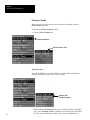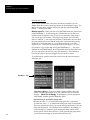
1
ALLEN-BRADLEY Bulletin 5370 CVIM USER–PAK Option (Catalog No. 5370–UPK) User Manual ALLEN-BRADLEY Important User Information Solid state equipment has operational characteristics differing from those of electromechanical equipment. “Application Considerations for Solid State Controls” (Publication SGI-1.1) describes some important differences between solid state equipment and hard–wired electromechanical devices. Because of this difference, and also because of the wide variety of uses for solid state equipment, all persons responsible for applying this equipment must satisfy themselves that each intended application of this equipment is acceptable. In no event will the Allen-Bradley Company be responsible or liable for indirect or consequential damages resulting from the use or application of this equipment. The examples and diagrams in this manual are included solely for illustrative purposes. Because of the many variables and requirements associated with any particular installation, the Allen-Bradley Company cannot assume responsibility or liability for actual use based on the examples and diagrams. No patent liability is assumed by Allen-Bradley Company with respect to use of information, circuits, equipment, or software described in this manual. Reproduction of the contents of this manual, in whole or in part, without written permission of the Allen-Bradley Company is prohibited. 1992 Allen-Bradley Company, Inc. Table of Contents USER–PAK Option User Manual A–B Using This Manual Chapter 1 Chapter Objectives . . . . . . . . . . . . . . . . . . . . . . . . . . . . . . . . . . . . . . . . . Manual Contents . . . . . . . . . . . . . . . . . . . . . . . . . . . . . . . . . . . . . . . . . . Intended Audience . . . . . . . . . . . . . . . . . . . . . . . . . . . . . . . . . . . . . . . . . Cautions . . . . . . . . . . . . . . . . . . . . . . . . . . . . . . . . . . . . . . . . . . . . . . . . . Related Publications . . . . . . . . . . . . . . . . . . . . . . . . . . . . . . . . . . . . . . . Trademarks . . . . . . . . . . . . . . . . . . . . . . . . . . . . . . . . . . . . . . . . . . . . . . Introduction to the USER–PAK Option Chapter 2 Installation Chapter 3 Chapter Objectives . . . . . . . . . . . . . . . . . . . . . . . . . . . . . . . . . . . . . . . . . Security Levels . . . . . . . . . . . . . . . . . . . . . . . . . . . . . . . . . . . . . . . . . . . Custom Menu Modifications . . . . . . . . . . . . . . . . . . . . . . . . . . . . . . . . . Custom Serial Port Messages . . . . . . . . . . . . . . . . . . . . . . . . . . . . . . . . Custom Runtime Displays . . . . . . . . . . . . . . . . . . . . . . . . . . . . . . . . . . . Copy and Paste Functions . . . . . . . . . . . . . . . . . . . . . . . . . . . . . . . . . . . Loading CVIM / USER–PAK Configurations . . . . . . . . . . . . . . . . . . . Connect and Use a Mouse . . . . . . . . . . . . . . . . . . . . . . . . . . . . . . . . . . . Chapter Objectives . . . . . . . . . . . . . . . . . . . . . . . . . . . . . . . . . . . . . . . . . The Two USER–PAK Memory Cards . . . . . . . . . . . . . . . . . . . . . . . . . . Installing the USER–PAK Option . . . . . . . . . . . . . . . . . . . . . . . . . . . . . Using the Setup Card . . . . . . . . . . . . . . . . . . . . . . . . . . . . . . . . . . . . . . . Accessing Setup Mode with USER–PAK Installed . . . . . . . . . . . . . . . . Getting Started / Using the Security Levels Chapter 4 Modifying the CVIM Menus Chapter 5 Chapter Objectives . . . . . . . . . . . . . . . . . . . . . . . . . . . . . . . . . . . . . . . . . Some Questions and Answers about System Security . . . . . . . . . . . . . Accessing the Setup Mode . . . . . . . . . . . . . . . . . . . . . . . . . . . . . . . . . . . Security Levels . . . . . . . . . . . . . . . . . . . . . . . . . . . . . . . . . . . . . . . . . . . Security Level Indication . . . . . . . . . . . . . . . . . . . . . . . . . . . . . . . . . Changing Passwords . . . . . . . . . . . . . . . . . . . . . . . . . . . . . . . . . . . . . . . Setting Security ON/OFF . . . . . . . . . . . . . . . . . . . . . . . . . . . . . . . . . . . Lost Passwords – Using the Installation / Key Card . . . . . . . . . . . . . . . Chapter Objectives . . . . . . . . . . . . . . . . . . . . . . . . . . . . . . . . . . . . . . . . . Deletion . . . . . . . . . . . . . . . . . . . . . . . . . . . . . . . . . . . . . . . . . . . . . . . . . Summary – Effects of Deletion . . . . . . . . . . . . . . . . . . . . . . . . . . . . Deletion Procedure . . . . . . . . . . . . . . . . . . . . . . . . . . . . . . . . . . . . . . Example – Menu Item Deletion . . . . . . . . . . . . . . . . . . . . . . . . The Cascade Effect . . . . . . . . . . . . . . . . . . . . . . . . . . . . . . . . . . . . . . Text Modification . . . . . . . . . . . . . . . . . . . . . . . . . . . . . . . . . . . . . . . . . 1–1 1–1 1–2 1–2 1–2 1–2 2–1 2–1 2–2 2–3 2–4 2–5 2–5 2–5 3–1 3–1 3–1 3–4 3–5 4–1 4–1 4–2 4–3 4–5 4–5 4–8 4–8 5–1 5–1 5–1 5–2 5–4 5–5 5–6 i Table of Contents USER–PAK Option User Manual Searching for Text . . . . . . . . . . . . . . . . . . . . . . . . . . . . . . . . . . . . . . Text String Search . . . . . . . . . . . . . . . . . . . . . . . . . . . . . . . . . . Dictionary ID Search . . . . . . . . . . . . . . . . . . . . . . . . . . . . . . . . Editing Text . . . . . . . . . . . . . . . . . . . . . . . . . . . . . . . . . . . . . . . . . . . Examples of Modifying Text . . . . . . . . . . . . . . . . . . . . . . . . . . . . . . Archiving Menu Modifications . . . . . . . . . . . . . . . . . . . . . . . . . . . . . . . Memory Requirement . . . . . . . . . . . . . . . . . . . . . . . . . . . . . . . . . . . . . . Creating Custom Serial Port Messages Chapter 6 Creating Custom Runtime Displays Chapter 7 ii Chapter Objectives . . . . . . . . . . . . . . . . . . . . . . . . . . . . . . . . . . . . . . . . . Some Questions and Answers about Custom Serial Port Messages . . . Creating Custom Serial Port Messages . . . . . . . . . . . . . . . . . . . . . . . . . Example of a Serial Port Message String . . . . . . . . . . . . . . . . . . . . . Basic Steps for Creating Custom Serial Port Messages . . . . . . . . . . Defining Strings . . . . . . . . . . . . . . . . . . . . . . . . . . . . . . . . . . . . . . . . Using Transmit Now . . . . . . . . . . . . . . . . . . . . . . . . . . . . . . . . . Defining the Serial Port . . . . . . . . . . . . . . . . . . . . . . . . . . . . . . . . . . . . . Erase Port Data . . . . . . . . . . . . . . . . . . . . . . . . . . . . . . . . . . . . . . . . . Buffer: Wait / No Wait . . . . . . . . . . . . . . . . . . . . . . . . . . . . . . . . . . . RS–232 Port Connections and Configuration . . . . . . . . . . . . . . . . . . . . Equipment Connections . . . . . . . . . . . . . . . . . . . . . . . . . . . . . . . . . . Selecting Serial Port Parameters . . . . . . . . . . . . . . . . . . . . . . . . . . . Chapter Objectives . . . . . . . . . . . . . . . . . . . . . . . . . . . . . . . . . . . . . . . . . Some Questions and Answers about Custom Runtime Displays . . . . . Initial Setup: Selecting and Defining the Viewport . . . . . . . . . . . . . . . Using the Define Viewport Menu . . . . . . . . . . . . . . . . . . . . . . . . . . Selecting the Viewport Type . . . . . . . . . . . . . . . . . . . . . . . . . . . Using Pick & Place . . . . . . . . . . . . . . . . . . . . . . . . . . . . . . . . . . Selecting Border and Background Colors . . . . . . . . . . . . . . . . Selecting Display Pages and Page Numbers . . . . . . . . . . . . . . Erase Port Data . . . . . . . . . . . . . . . . . . . . . . . . . . . . . . . . . . . . . Defining Text and Tool Viewport Contents . . . . . . . . . . . . . . . . . . . . . . Using the Define String Menu . . . . . . . . . . . . . . . . . . . . . . . . . . . . . Selecting String Direction . . . . . . . . . . . . . . . . . . . . . . . . . . . . Selecting String Width . . . . . . . . . . . . . . . . . . . . . . . . . . . . . . . Selecting String Color . . . . . . . . . . . . . . . . . . . . . . . . . . . . . . . Using Pick & Place . . . . . . . . . . . . . . . . . . . . . . . . . . . . . . . . . . The Copy and Paste Features . . . . . . . . . . . . . . . . . . . . . . . . . . . . . . Defining Graph Viewports . . . . . . . . . . . . . . . . . . . . . . . . . . . . . . . . . . . Selecting the Variable . . . . . . . . . . . . . . . . . . . . . . . . . . . . . . . . . . . . Defining the Variable . . . . . . . . . . . . . . . . . . . . . . . . . . . . . . . . . . . . 5–6 5–7 5–8 5–10 5–13 5–15 5–15 6–1 6–1 6–2 6–2 6–3 6–4 6–4 6–5 6–6 6–6 6–8 6–8 6–9 7–1 7–1 7–3 7–4 7–4 7–6 7–8 7–9 7–11 7–12 7–13 7–14 7–15 7–15 7–16 7–17 7–18 7–19 7–20 Table of Contents USER–PAK Option User Manual Setting the Style . . . . . . . . . . . . . . . . . . . . . . . . . . . . . . . . . . . . Selecting Variable Color . . . . . . . . . . . . . . . . . . . . . . . . . . . . . . Selecting the Variable Tool . . . . . . . . . . . . . . . . . . . . . . . . . . . . Defining the Graph . . . . . . . . . . . . . . . . . . . . . . . . . . . . . . . . . . . . . . Defining the Viewport Limits – Upper and Lower . . . . . . . . . Defining the Event . . . . . . . . . . . . . . . . . . . . . . . . . . . . . . . . . . Defining Strings for Serial Ports and Viewports Chapter 8 Using Copy and Paste Chapter 9 Chapter Objectives . . . . . . . . . . . . . . . . . . . . . . . . . . . . . . . . . . . . . . . . . Entering (or Modifying) String Text . . . . . . . . . . . . . . . . . . . . . . . . . . . Valid Elements of String Text . . . . . . . . . . . . . . . . . . . . . . . . . . . . . . . . Literal Text . . . . . . . . . . . . . . . . . . . . . . . . . . . . . . . . . . . . . . . . . . . . Data Codes . . . . . . . . . . . . . . . . . . . . . . . . . . . . . . . . . . . . . . . . . . . . Special Characters: N, /, %, # . . . . . . . . . . . . . . . . . . . . . . . . . . . . . . The N (newline) character . . . . . . . . . . . . . . . . . . . . . . . . . . . / Character Code Indicator . . . . . . . . . . . . . . . . . . . . . . . . . . . . % Formula Indicator . . . . . . . . . . . . . . . . . . . . . . . . . . . . . . . . . # (Index) Character . . . . . . . . . . . . . . . . . . . . . . . . . . . . . . . . . . Field Formatting Codes . . . . . . . . . . . . . . . . . . . . . . . . . . . . . . . . . . Conditional Color–coding . . . . . . . . . . . . . . . . . . . . . . . . . . . . . . . . Extended Conditional Color–coding . . . . . . . . . . . . . . . . . . . . Draw Line Codes . . . . . . . . . . . . . . . . . . . . . . . . . . . . . . . . . . . . . . . Plot Line Codes . . . . . . . . . . . . . . . . . . . . . . . . . . . . . . . . . . . . . . . . Change Color Codes . . . . . . . . . . . . . . . . . . . . . . . . . . . . . . . . . . . . . Summary of Codes and Indicators . . . . . . . . . . . . . . . . . . . . . . . . . . Defining the Event . . . . . . . . . . . . . . . . . . . . . . . . . . . . . . . . . . . . . . . . . Using Repeat String . . . . . . . . . . . . . . . . . . . . . . . . . . . . . . . . . . . . . . . . Custom Serial Port Message Example . . . . . . . . . . . . . . . . . . . . . . . . . . Text and Tool Viewport Examples . . . . . . . . . . . . . . . . . . . . . . . . . . . . Example 1 – Creating a Special Character . . . . . . . . . . . . . . . . . . . . Example 2 – Using the Change Color Code . . . . . . . . . . . . . . . . . . . Example 3 – Using the Draw Line Code . . . . . . . . . . . . . . . . . . . . . Example 4 – Using Repeat String and # (Index) Character . . . . . . . Example 5 – Using Data Codes and # (Index) Character . . . . . . . . . Example 6 – Conditionally Displaying a Text String . . . . . . . . . . . . Example 7 – Using Formulas and Plot Line Codes . . . . . . . . . . . . . Chapter Objectives . . . . . . . . . . . . . . . . . . . . . . . . . . . . . . . . . . . . . . . . . Using Copy and Paste . . . . . . . . . . . . . . . . . . . . . . . . . . . . . . . . . . . . . . Example – Tool Copy and Paste . . . . . . . . . . . . . . . . . . . . . . . . . . . Example – Viewport Copy and Paste . . . . . . . . . . . . . . . . . . . . . . . . Example – String Copy and Paste . . . . . . . . . . . . . . . . . . . . . . . . . . 7–20 7–21 7–22 7–22 7–23 7–24 8–1 8–1 8–3 8–3 8–4 8–7 8–7 8–8 8–8 8–9 8–10 8–13 8–14 8–14 8–18 8–18 8–20 8–20 8–26 8–30 8–33 8–34 8–35 8–36 8–37 8–39 8–41 8–42 9–1 9–1 9–2 9–3 9–4 iii Table of Contents USER–PAK Option User Manual Loading CVIM / USER–PAK Configurations Chapter 10 Connecting and Using a Mouse Appendix A Character Codes Appendix B Chapter Objectives . . . . . . . . . . . . . . . . . . . . . . . . . . . . . . . . . . . . . . . . . Loading CVIM / USER–PAK Configurations . . . . . . . . . . . . . . . . . . . Checking Available Memory . . . . . . . . . . . . . . . . . . . . . . . . . . . . . . . . . Objective . . . . . . . . . . . . . . . . . . . . . . . . . . . . . . . . . . . . . . . . . . . . . . . . Hardware Requirements and Considerations . . . . . . . . . . . . . . . . . . . . . Connections – CVIM Module Hardware Series A and B . . . . . . . . Configuring the CVIM Module . . . . . . . . . . . . . . . . . . . . . . . . . . . . . . . Using a Mouse . . . . . . . . . . . . . . . . . . . . . . . . . . . . . . . . . . . . . . . . . . . . Types of Mouse and Trackball Supported . . . . . . . . . . . . . . . . . . . . Objective . . . . . . . . . . . . . . . . . . . . . . . . . . . . . . . . . . . . . . . . . . . . . . . . ASCII Commands for the USER–PAK Option 10–1 10–1 10–3 A–1 A–1 A–1 A–1 A–2 A–3 B–1 Appendix C Objective . . . . . . . . . . . . . . . . . . . . . . . . . . . . . . . . . . . . . . . . . . . . . . . . ASCII Commands . . . . . . . . . . . . . . . . . . . . . . . . . . . . . . . . . . . . . . . . . Force Print Command . . . . . . . . . . . . . . . . . . . . . . . . . . . . . . . . . . . Force Print for Viewport Strings . . . . . . . . . . . . . . . . . . . . . . . Force Print for Serial Port Strings . . . . . . . . . . . . . . . . . . . . . . Write String Data Command . . . . . . . . . . . . . . . . . . . . . . . . . . . . . . Read String Data Command . . . . . . . . . . . . . . . . . . . . . . . . . . . . . . . Suspend / Resume Serial Port Output Command . . . . . . . . . . . . . . . Write Display Command (Enhancement) . . . . . . . . . . . . . . . . . . . . . C–1 C–1 C–1 C–1 C–2 C–2 C–3 C–3 C–3 Index Tables 1.A 4.A 8.A 8.B 8.C B.1 B.2 iv Chapter Descriptions . . . . . . . . . . . . . . . . . . . . . . . . . . . . . . . . . . . . . Functions/Features at each Security Level . . . . . . . . . . . . . . . . . . . . Data Codes . . . . . . . . . . . . . . . . . . . . . . . . . . . . . . . . . . . . . . . . . . . . . Color Codes for Strings . . . . . . . . . . . . . . . . . . . . . . . . . . . . . . . . . . . Special Characters and Indicators for Defining Strings . . . . . . . . . . ASCII Control Codes (Serial Ports Only) . . . . . . . . . . . . . . . . . . . . Character Codes (Serial Ports and Viewports) . . . . . . . . . . . . . . . . . 1–1 4–4 8–4 8–19 8–20 B–1 B–2 Chapter A–B 1 Using This Manual Contents Chapter Objectives . . . . . . . . . . . . . . . . . . . . . . . . . . . . . . . . . . . . . . . . Manual Contents . . . . . . . . . . . . . . . . . . . . . . . . . . . . . . . . . . . . . . . . . . Intended Audience . . . . . . . . . . . . . . . . . . . . . . . . . . . . . . . . . . . . . . . . Cautions . . . . . . . . . . . . . . . . . . . . . . . . . . . . . . . . . . . . . . . . . . . . . . . . Related Publications . . . . . . . . . . . . . . . . . . . . . . . . . . . . . . . . . . . . . . . Trademarks . . . . . . . . . . . . . . . . . . . . . . . . . . . . . . . . . . . . . . . . . . . . . . 1–1 1–1 1–2 1–2 1–2 1–2 Chapter Objectives The objective of this chapter is to provide an overview of the contents and organization of this manual, to describe the intended audience, and to list related publications. Manual Contents The contents of this manual are briefly described in Table 1.A below. Table 1.A Chapter Descriptions Ch/App Title 1 Using This Manual Provides an overview of the manual. 2 Introduction to the USER–PAK Option 3 Installation Previews the main features and capabilities of the USER–PAK option. Describes how to install the USER–PAK option into the CVIM module, and discusses the use of the two memory cards. 4 Getting Started / Using Security Levels 5 Modifying the CVIM Menus 6 7 8 9 10 A Creating Custom Serial Port Messages Creating Custom Runtime Displays Defining Strings for Serial Ports and Viewports Using Copy and Paste Loading CVIM / USER–PAK Configurations Connecting and Using a Mouse B Character Codes C ASCII Commands for the USER–PAK Option Description Describes how to access the setup mode, and how to set up the different security levels. Describes how to delete menu items, and how to modify the text of menu items. Describes how to create custom messages for transmission through a serial port. Describes how to create custom displays which appear during runtime. Describes how to enter string text, use valid string elements, and set event and repetition parameters for strings. Describes how to use the Copy and Paste functions to copy the settings directly from one tool to another of the same type, copy one string to another, or copy one viewport or serial port to another. Describes how to load specific portions of CVIM / USER–PAK configurations. Describes how to connect and use a mouse for interfacing with the CVIM screen menus. Lists the ASCII characters and CVIM module graphics characters that can be generated within strings using the character codes. Describes the serial port ASCII commands which apply specifically if the USER–PAK option is installed. 1–1 Chapter 1 Using This Manual Intended Audience Before using this manual, you should be familiar with the CVIM module features and the procedures used in configuring the CVIM module for operation. • • • Cautions For information regarding the CVIM module, refer to the CVIM User’s Manual, Cat. No. 5370–ND001 (Series B) and Addendum. If you plan to use the CVIM communications port (RS–232), refer also to the CVIM Communications Manual, Cat. No. 5370–ND002 (Series B). If you plan to use other software option packages along with the USER–PAK option, refer to the user’s manuals for the respective software package as necessary. Notices of caution are included when the CVIM module or peripheral equipment could be damaged if the listed procedure is not followed. The following format is used: CAUTION: This is the format used for a caution. Related Publications The following manuals are cited for reference in this manual: • • Trademarks User’s Manual, Bulletin 5370–CVIM, Cat. No. 5370–ND001 (Series B) and Addendum, also referred to as the CVIM User’s Manual in this publication. Communications Manual, Bulletin 5370–CVIM, Cat. No. 5370–ND002 (Series B) also referred to as the CVIM Communications Manual in this publication. The following trademarks apply to products mentioned in this manual: USER–PAK Option – Allen–Bradley Cat. No. 5370–UPK CVIM Module – Allen–Bradley Cat. No. 5370–CVIM MATH–PAK Option – Allen–Bradley Cat. No. 5370–MPK OCR–PAK Option – Allen–Bradley Cat. No. 5370–OCR 1–2 Chapter A–B 2 Introduction to the USER–PAK Option Contents Chapter Objectives . . . . . . . . . . . . . . . . . . . . . . . . . . . . . . . . . . . . . . . . Security Levels . . . . . . . . . . . . . . . . . . . . . . . . . . . . . . . . . . . . . . . . . . . Custom Menu Modifications . . . . . . . . . . . . . . . . . . . . . . . . . . . . . . . . . Custom Serial Port Messages . . . . . . . . . . . . . . . . . . . . . . . . . . . . . . . . Custom Runtime Displays . . . . . . . . . . . . . . . . . . . . . . . . . . . . . . . . . . . Copy and Paste Functions . . . . . . . . . . . . . . . . . . . . . . . . . . . . . . . . . . Loading CVIM / USER–PAK Configurations . . . . . . . . . . . . . . . . . . . . . . Connect and Use a Mouse . . . . . . . . . . . . . . . . . . . . . . . . . . . . . . . . . . . 2–1 2–1 2–2 2–3 2–4 2–5 2–5 2–5 Chapter Objectives This chapter briefly describes the features and capabilities of the USER–PAK option package. Security Levels When USER–PAK is installed in your CVIM module, access to the setup mode can require the use of a password. The password is entered through a pop–up keyboard which appears automatically when you attempt to enter the setup mode (as shown below). 2–1 Chapter 2 Introduction to the USER–PAK Option The USER–PAK option enables access to four different levels of interaction; we refer to these different levels as “security levels.” The different security levels allow for implementation of a hierarchical system of access to and responsibility for the CVIM module setup. Three security levels are defined within the setup mode, each allowing a different level of interaction with CVIM / USER–PAK features: • • • ADMINISTRATOR – Full access to CVIM / USER–PAK features. MANAGER – Mid–level access to CVIM / USER–PAK features. USER – Lower–level access to CVIM / USER–PAK features. Access to the above security levels is controllable through the assignment of a specific password for each level. Access to CVIM runtime menus and displays does not require a password – this “runtime” level of interaction can be considered as a fourth level of security. Custom Menu Modifications The USER–PAK option allows the ADMINISTRATOR to modify the CVIM module user–interface in two ways – through deletion of menu items from the CVIM pop–up menus, and/or modification of text. Deletion: A menu item is marked for deletion at the ADMINISTRATOR level; menu items marked for deletion do not appear on the monitor screen at the USER level. Any subsequent menu(s) that would have been accessible through the use of the deleted menu item are unavailable as well. “Trash can” icon open (icon is green when open) Delete function enabled To enable the delete function, you pick the “trash can” icon, which appears at the ADMINISTRATOR level; then you select or “mark” menu items for deletion. 2–2 Chapter 2 Introduction to the USER–PAK Option Text Modification: The USER–PAK option enables the ADMINISTRATOR to modify the text of menu items, and of on–screen messages such as the help messages or the power–up title banner. To modify text, you use the Change Text feature (accessed from the Env. menu). Custom Serial Port Messages For communication between the CVIM module and a remote device, the CVIM module has a serial port (CVIM module series A has one serial port, series B or later, two serial ports). With the USER–PAK option installed, you can create your own custom serial port messages for transmission through the serial port. The messages consist of ASCII characters. These messages are transmitted automatically by the CVIM module – they need not be “solicited” (requested by command) by the connected device. You create serial port messages using the Config. Output feature, which becomes available on the Env. menu with the USER–PAK option installed. 2–3 Chapter 2 Introduction to the USER–PAK Option Within each message you can send literal text, results and other data on specific tools, statistical data, and other information. You also define the conditions under which a serial message is transmitted – the message can be sent after each inspection, or only upon certain conditions, such as the failure of a specific tool, for instance. Custom Runtime Displays 2–4 Runtime displays are those displays which appear on the monitor while the CVIM is operating in run mode. You create custom runtime displays by configuring “viewports,” using the Config. Output feature, which becomes available on the Env. menu with the USER–PAK option installed. You select display borders and background color, and you define the viewport contents. Viewports can contain text, numerical data, line graphics, and real–time graphs. You also define the conditions under which viewport contents are displayed – the contents can be displayed after each inspection, or only upon certain conditions, such as the failure of a specific tool, for instance. Chapter 2 Introduction to the USER–PAK Option Copy and Paste Functions With the USER–PAK option installed, you can copy the settings from one gage or window to another using the Copy and Paste menu items which are part of the new USER–PAK menus, and which become part of the previous CVIM gage and window menus. You can also copy the contents of serial ports or viewports and their respective strings. Window menu Copy and Paste Loading CVIM / USER–PAK Configurations With USER–PAK installed, you can selectively load portions of the default configuration or the internally stored configuration. This allows you, for example, to load previously–stored user interface modifications, while retaining a new CVIM inspection configuration. Archival menu Connect and Use a Mouse Load Config ( Int ) menu With the USER–PAK option installed, you can connect a mouse or trackball to a CVIM serial port, and use the mouse to configure the CVIM, instead of the light pen. 2–5 Chapter A–B 3 Installation Contents Chapter Objectives . . . . . . . . . . . . . . . . . . . . . . . . . . . . . . . . . . . . . . . . The Two USER–PAK Memory Cards . . . . . . . . . . . . . . . . . . . . . . . . . . . Installing the USER–PAK Option . . . . . . . . . . . . . . . . . . . . . . . . . . . . . . Using the Setup Card . . . . . . . . . . . . . . . . . . . . . . . . . . . . . . . . . . . . . . Accessing Setup Mode with USER–PAK Installed . . . . . . . . . . . . . . . . . 3–1 3–1 3–1 3–4 3–5 Chapter Objectives This chapter describes how to install the USER–PAK option in the Allen–Bradley 5370–CVIM machine vision system, including the use of the two memory cards on which the USER–PAK option software resides. The Two USER–PAK Memory Cards The USER–PAK option is provided on two different memory cards. These two cards are labeled Installation / Key card and Setup card respectively. The purpose of each card is described below: • • Installing the USER–PAK Option Installation / Key card – This card serves two purposes: Use this card to install the USER–PAK option into the CVIM module. Use this card also to access the setup mode in the case of lost passwords. Important: Because this card can be used to override the CVIM system security (see Chapter 4), it is suggested that this card be kept in a secure place when not in use, and that access to this card be allowed only to the appropriate authorized personnel. Setup card – Insert this card into the Archive Memory slot after the USER–PAK option has been installed. This card must remain in the Archive Memory slot during setup mode in order to access most of the USER–PAK option capabilities. This section describes how to install the USER–PAK option. Installing More than One Option: The USER–PAK option is entirely compatible with any of the other CVIM option packages. You can install the option packages in any order, with this exception – you must install the MATH–PAK option before installing the USER–PAK option. Installing the MATH–PAK option after installing the USER–PAK option nullifies the USER–PAK option; if this happens, you must reinstall the USER–PAK option. Required Firmware: The CVIM system must have the Revision C03 (or higher) firmware before the USER–PAK option can be installed (the 3–1 Chapter 3 Installation firmware revision is listed on the title banner on the monitor screen following powerup). One–Time Installation: You need only install the USER–PAK option once; once installed, the USER–PAK option remains installed for all subsequent powerups. To install the USER–PAK option in your CVIM module: • • Remove DC power from the CVIM module by pulling out the DC PWR / LOCK handle on the power supply module as far as it will go. Insert the Installation / Key card into the Archive Memory slot on the CVIM module. Insert the end with the metal strip facing right: CVIM Module USER–PAK Installation/Key card Card Label • Metal Strip ÇÇÇÇ ÇÇÇÇ ÇÇÇÇ ÇÇÇÇ ÇÇÇÇ ÇÇÇÇ ÇÇÇÇ ÇÇÇÇ ÇÇÇÇ ÇÇÇÇ ÇÇÇÇ ÇÇÇÇ ÇÇÇÇ ÇÇÇÇ ÇÇÇÇ ÇÇÇÇ ÇÇÇÇ Push in the DC PWR / LOCK handle as far as possible. This applies DC power to the CVIM module, and starts the loading sequence. CAUTION: Do not remove power to the CVIM module during loading of the USER–PAK option. Doing so may damage the CVIM module. 3–2 Chapter 3 Installation The top three LEDs on the CVIM module indicate the progress of the three–phase loading process, as follows: USER–PAK Loading Phase LEDs 1 2 3 Pass/Fail Red–to–yellow– to–green Green Red–to–yellow– to–green Trigger 1 Green Green Off Trigger 2 Off Green Green The loading process requires about 45 seconds, with each phase taking about 15 seconds. When the loading process is complete, the CVIM module begins its normal powerup sequence. • • Verify that the USER–PAK option is installed by checking the title banner on the monitor after power–up; if the USER–PAK option is installed, there is a message on the banner indicating the presence of the USER–PAK option. Remove the Installation / Key card from the Archive Memory slot. Card Security: Because the Installation / Key card can be used to override the CVIM system security (see Chapter 4), it is suggested that this card be kept in a secure place when not in use, and that access to this card be allowed only to the appropriate authorized personnel. 3–3 Chapter 3 Installation Using the Setup Card To access most, but not all, of the USER–PAK features while in setup mode, the Setup card must be inserted. To insert the Setup card: • • Insert the Setup card into the Archive Memory slot on the CVIM module with the card’s metal strip facing right. Leave the Setup card in the Archive Memory slot as required during your configuration of the CVIM module. Setup Card Requirement: Most USER–PAK features require the Setup card be inserted; the only features which do not require the Setup card are Change Password (see Chapter 4), and the Copy and Paste feature for tools (see Chapter 9). When the Setup card must be inserted to access a feature, this is specifically stated within the description of the feature in this manual. Removing the Setup Card: You may remove the Setup card from the CVIM module at any time – except when the Memory Active LED on the CVIM module is ON. The Memory Active LED goes ON during setup mode when certain USER–PAK features are used. CAUTION: Do not remove the Setup card from the Archive Memory slot when the Memory Active LED on the CVIM module is ON. Doing so will cause the CVIM module to shut down, which will result in the loss of your working configuration (the internally–stored configuration is not effected). Restarting the CVIM module: If the CVIM module operation has shut down due to Setup card removal with the Memory Active LED ON, restart the CVIM module when appropriate by cycling CVIM module power off and on again. 3–4 Chapter 3 Installation Accessing Setup Mode with USER–PAK Installed Upon installation of the USER–PAK option, access to the setup mode requires the use of a password. The password is entered through a pop–up keyboard which appears when you pick the Setup box: Password entry keyboard Note: The password requirement for entry can be disabled; see Chapter 4 for more information on entering the setup mode. 3–5 Chapter A–B 4 Getting Started / Using the Security Levels Contents Chapter Objectives . . . . . . . . . . . . . . . . . . . . . . . . . . . . . . . . . . . . . . . . Some Questions and Answers about System Security . . . . . . . . . . . . . Accessing the Setup Mode . . . . . . . . . . . . . . . . . . . . . . . . . . . . . . . . . . Security Levels . . . . . . . . . . . . . . . . . . . . . . . . . . . . . . . . . . . . . . . . . . . Changing Passwords . . . . . . . . . . . . . . . . . . . . . . . . . . . . . . . . . . . . . . Setting Security ON/OFF . . . . . . . . . . . . . . . . . . . . . . . . . . . . . . . . . . . . Lost Passwords – Using the Installation/Key Card . . . . . . . . . . . . . . . . Chapter Objectives This chapter describes: • • • • Some Questions and Answers about System Security 4–1 4–1 4–2 4–3 4–5 4–8 4–8 How to enter the setup mode with the USER–PAK option installed. Each of the security levels. How to change passwords. How to enter setup mode using the Installation / Key Card. This section introduces security by posing some questions and answers. What type of system security does USER–PAK provide? With the USER–PAK option installed, access to the setup mode requires a password (unless security is turned OFF – see Setting Security ON/OFF in this chapter). The password requirement can help provide assurance against unauthorized modification of the CVIM configuration, and help prevent unauthorized personnel from taking the CVIM module out of run mode. What are “security levels?” The USER–PAK system security enables access to four different levels of interaction; we refer to these different levels as “security levels.” Three security levels are defined within the setup mode, each allowing a different level of interaction with CVIM / USER–PAK features: • ADMINISTRATOR – Full access to CVIM / USER–PAK features. • MANAGER – Mid–level access to CVIM / USER–PAK features. • USER – Lower–level access to CVIM / USER–PAK features. Access to CVIM runtime menus and displays does not require a password – this “runtime” level of interaction can be considered as a fourth level of security. Why have different security levels available? The different security levels allow for implementation of a hierarchical system of access to and responsibility for the CVIM module setup. For 4–1 Chapter 4 Getting Started / Using the Security Levels instance, a system “administrator” can be designated; this person would have access to the ADMINISTRATOR level. The ADMINISTRATOR could be responsible for creating restrictions to the menu items available at the user level (through menu item deletion), for modifying menu item text, and for maintenance and security of the passwords which allow access to the different levels. A “manager” can be designated, having access to the MANAGER level (that is, having access to any deleted menus items). Designated “users” would have access to the USER level; a “user” cannot, for example, modify menus, change passwords, or set security ON or OFF. The “user” is able to use the other USER–PAK and base CVIM module capabilities, except those deleted from the menus at the system administrator level. Finally, at the “runtime” level, only use of runtime menus and displays is available. How do you enter a password for access to the setup mode? You enter the password through the password keyboard; this keyboard appears automatically when you select Setup on the runtime screen. What happens if a password is lost? Entry to the setup mode can be enabled through the use of the USER–PAK Installation/Key card, should passwords be lost. See “Lost Passwords – Using the Installation/Key Card” later in this chapter. Accessing the Setup Mode After USER–PAK installation, accessing the setup mode requires entry of a password (unless security has been turned off – see “Setting Security ON/OFF” later in this chapter). To enter the setup mode from run mode or standby mode: • Pick the Setup box on the runtime display, which causes the password keyboard to appear. • Enter the appropriate password on the keyboard, and then pick Ret. 4–2 Chapter 4 Getting Started / Using the Security Levels Listed below are further considerations for accessing the setup mode: First Time Entry – Default Password: For entering the setup mode the first time after installing the USER–PAK option, the default 3–character password is A–B. The initial entry will access the ADMINISTRATOR level of the setup mode. Non–unique passwords: If the same password is assigned for two or more levels, the password will access the highest level for that password. Case–sensitivity: Password entry is case–sensitive. Use the “shift” arrow key (lower left/right corners) to access the lower–case keyboard if necessary. Password Display: The characters you select will appear as asterisks to the right of Password: in the keyboard display. Incorrect password: If you have not entered the password correctly, the Status: line in the keyboard will display Incorrect Password: If this happens, simply try entering the password again. You can try as many times as is necessary to correctly enter the password. No Keyboard – Setup Mode entered Directly: If, when you pick the Setup box, the CVIM module goes directly to setup mode, this indicates Security has been turned OFF (see “Setting Security ON/OFF” later in this chapter to display the password entry keyboard with security OFF). Security Levels When you enter the setup mode with USER–PAK installed, you enter one of three security levels of the setup mode – ADMINISTRATOR, MANAGER, or USER level (see “Accessing the Setup Mode” in this chapter). A fourth security level is the “runtime” level – access to runtime menus and displays during run mode – which does not require a password. You cannot change your current security level directly within setup mode. To change security levels, you must exit to run mode, then reenter setup mode using the appropriate password for the security level you want to enter. The different security levels each allow a different level of interaction with the base CVIM module functions and USER–PAK functions. Table 4.A summarizes the features and functions available at each security level. 4–3 Chapter 4 Getting Started / Using the Security Levels Table 4.A Functions/Features at each Security Level Security Level Functions/ Features Administrator Change Password n Set Security ON/OFF n Change Text n Menu Item Deletion1 Manager User n Access Deleted Menu Items n n Define Serial Ports n n n2 Define Viewports n n n2 (Base CVIM) Setup Mode Functions n n n2 All Runtime Menus/Displays n n n 1Menu item deletion can be used to 2 Availability of functions at USER Runtime n selectively delete (deny access to) setup mode functions that are otherwise available at the USER level. level depends on which menu items are deleted. As shown in Table 4.A, the ADMINISTRATOR level allows access to all the USER–PAK option and base CVIM functions, including exclusive access to the first four functions listed. The ADMINISTRATOR for a given system can thus be assigned sole responsibility for: creating restrictions to the menu items available at the user level (through menu item deletion); for modifying menu item text; for setting Security ON/OFF; and/or for assigning the passwords which allow access to the different levels. Note that the subset of features available at the MANAGER and USER levels is identical, except that the MANAGER has access to menu items which have been deleted, while the USER does not. Thus the degree of difference in available features at these two levels, for a given system, is determined by the ADMINISTRATOR (through menu item deletion). 4–4 Chapter 4 Getting Started / Using the Security Levels Security Level Indication While in setup mode with the USER–PAK option installed, the icons in the upper right corner of the screen indicate the current security level: “Trash can” icon (Administrator Level) At the ADMINISTRATOR level, the trash can icon appears on the screen. “M” icon (Manager Level) If you have entered the MANAGER level, the letter “M” is displayed. If you have entered the USER level, no security–level icon is displayed. Changing Passwords This section describes the procedure for changing passwords. Passwords can be changed at the ADMINISTRATOR level only. Assigning unique passwords: In order to create the availability of access to each of the different security levels, you must assign a unique password to each level. If the same password is assigned for two or more levels, the password will access the highest level for that password. 4–5 Chapter 4 Getting Started / Using the Security Levels For example, if a particular password is used for both the ADMINISTRATOR and MANAGER levels, using that password will access the ADMINISTRATOR level. This means, in this case, the MANAGER level will not be accessible. Default Password: When first installed, the USER–PAK option assigns the default 3–character password A–B to all three security levels. Before you can access each different security level, you must assign a unique password to each level. Note: It is suggested, for greater security, that the passwords for the respective security levels be changed as soon as possible upon installing the USER–PAK option. Effect of Password Change: After changing a password, the new password is immediately stored in non–volatile memory; the next time you want to enter the setup mode at the security level for which you have just changed the password, you must use the new password. To change a password: • Pick Env. → Change Password to access the Password Level menu and display the keyboard: Security level selected Password keyboard • Pick the security level – Administrator, Manager, or User – for which you are changing the password, on the Password Level menu. • Enter the old (current) password for the selected level, or the ADMINISTRATOR level password, using the password keyboard, and then pick Ret. 4–6 • Enter the new password, and pick the Ret key. Chapter 4 Getting Started / Using the Security Levels Once you enter the new password, the keyboard prompts you to reenter the password in order to verify: • Enter the new password again and pick the Ret key. If the verification failed, go back to the “Enter the new password” step, and repeat the procedure from that point. When verification is successful, the Status: message indicates you have changed the password: Listed below are further considerations for changing the password: Case–sensitivity: Password entry is case–sensitive. Use the “shift” arrow key (lower left/right corners) to access the lower–case keyboard if necessary. Password Display: The characters you select will appear as asterisks to the right of Password: in the keyboard display. Password length / valid characters: You can enter from one to 16 characters (alphanumeric only) for the new password. Incorrect password: If you have not entered the old password correctly, the Status: line in the keyboard will display Incorrect Password: If this happens, simply try entering the password again. You can try as many times as is necessary to correctly enter the password. Exit without changing: If you want to exit the procedure without changing the password, pick the Esc key before completing the verification step. 4–7 Chapter 4 Getting Started / Using the Security Levels Setting Security ON / OFF The USER–PAK option allows the ADMINISTRATOR to disable security (that is, remove the password requirement) for entry into the setup mode. Below are descriptions of the effects of having Security: ON (enabled) and Security: OFF (disabled): • Security: ON – A password is required for access to the setup mode. Whenever you pick the Setup box, the password keyboard will appear (see “Accessing the Setup Mode” in this chapter). • Security: OFF – No password is required for entry to the setup mode. When you pick the Setup box, the CVIM module goes directly to setup mode. Security Level accessed with Security OFF: With Security OFF, picking the Setup box accesses the USER level of the setup mode, unless the USER level shares a common password with one or both of the other levels. In this case, the security level entered will be the highest level available through the common password. Displaying password keyboard with Security OFF: In order to display the password entry keyboard with security OFF, hold the tip of the light pen down upon the Setup box until the keyboard appears (about two seconds). If you are using a mouse, place the cursor over the Setup box, and hold the left mouse button down until the keyboard appears. To set Security to ON or OFF (available at ADMINISTRATOR level only): • Pick Exit box on the main menu to access the Exit menu: Security: box Exit: box • Pick the Security box to toggle the setting between ON and OFF. Default Setting: The default setting is Security: ON. Lost Passwords – Using the Installation / Key Card 4–8 The USER–PAK option provides a method to effectively override the password security feature, and enter the setup mode at the ADMINISTRATOR level. This is accomplished through the use of the Installation / Key card. This “Key” method of entry is especially important if the password for the administrator level is lost or is otherwise unavailable. Chapter 4 Getting Started / Using the Security Levels To enter the setup mode using the Installation / Key card, complete these steps: • If the CVIM module is in setup mode, go to run mode. • Insert the Installation / Key card into the Archive Memory slot on the CVIM module. • Pick the Setup box on the runtime menu to display the password entry keyboard (Note: If Security has been set to OFF, hold the tip of the light pen down upon the Setup box until the keyboard appears. If you are using a mouse, place the cursor over the Setup box, and hold the left mouse button until the keyboard appears). • Enter the 3–character default password A–B on the password entry keyboard, and pick the Ret key. After entering the setup mode at the ADMINISTRATOR level, it is possible to change the password for the ADMINISTRATOR level – or any other level. While the Installation / Key card is inserted, the default password A–B can be used as the “old password” when changing passwords (see “Changing Passwords” earlier in this chapter). 4–9 Chapter A–B 5 Modifying the CVIM Menus Contents Chapter Objectives . . . . . . . . . . . . . . . . . . . . . . . . . . . . . . . . . . . . . . . . 5–1 Deletion . . . . . . . . . . . . . . . . . . . . . . . . . . . . . . . . . . . . . . . . . . . . . . . . 5–1 Text Modification . . . . . . . . . . . . . . . . . . . . . . . . . . . . . . . . . . . . . . . . . . 5–6 Archiving Menu Modifications . . . . . . . . . . . . . . . . . . . . . . . . . . . . . . . . 5–15 Memory Requirement . . . . . . . . . . . . . . . . . . . . . . . . . . . . . . . . . . . . . . 5–15 Chapter Objectives The USER–PAK option provides two different ways of modifying the CVIM module menus. This chapter describes both how to: • Delete items from CVIM module screens. • Modify the text of the CVIM module’s menus and help messages. Note: The above capabilities are available at the ADMINISTRATOR level only. Deletion The USER–PAK option allows you to remove items from the CVIM pop–up menus, and other on–screen features. By deleting items, the ADMINISTRATOR can customize the USER level interface, limiting the user’s access to a subset of CVIM module functions. A menu item, or other interactive feature, is marked for deletion by the ADMINISTRATOR; the marked item subsequently is not displayed on the screen at the USER level. Any subsequent menu(s) that would have been accessible through the use of a deleted menu item are unavailable as well. Summary – Effects of Deletion Deletion affects functionality and appearance of the items differently at each of the setup mode security levels: • Administrator Level – Items can be marked for deletion at this level only. Although items marked for deletion are altered in appearance (an orange border is added), they retain normal functionality. • Manager Level – Item deletion does not effect this level; that is, all menu items are always available, and their appearance is unaltered, regardless of menu deletions. • User Level – Items marked for deletion do not appear on–screen at this level, and thus are not available to the user. 5–1 Chapter 5 Modifying the CVIM Menus Deletion Procedure Marking an item for deletion involves just a few basic steps (the following steps assume the ADMINISTRATOR level is accessed): • Insert the Setup card into the Archive Memory slot on the CVIM module. • Access the appropriate menu(s) so the item to be deleted is currently displayed on the monitor screen. • Activate the delete function – pick the “trash can” icon so the top of the “trash can” is open. This indicates the delete function is active. “Trash can” icon open (icon is green when open) Delete function enabled • Pick the item(s) to mark for deletion. Marked items are highlighted with an orange border: Menu Items Marked for Deletion • To unmark a marked item, pick the item again. • To deactivate the menu delete function when finished, pick the “trash can” icon so that it appears that the top of the “trash can” is closed. “Trash can” icon closed (icon is red when closed) Delete function disabled Here are some additional considerations when marking items for deletion: Paired Menu Items: Paired menu items occupying a single line, such as Copy/Paste, and Previous/Next, should be deleted as a pair. Otherwise menu items may overlap when displayed. Range of Effect: If an item which is marked for deletion is part of a menu which appears in more than one place, it is deleted from each menu 5–2 Chapter 5 Modifying the CVIM Menus where it normally appears, for both toolsets. For example, if you delete a color selection item from the Color Selection menu for a string, the item is deleted from any occurrence of the Color Selection menu – including Color Selection for viewport border and background, and for Graph variables. Other examples of menus which appear in more than one place include the Range / Output menu, and the Threshold / Filter menu. Menu Justification: When menu items are deleted from a menu, the remaining items, when displayed, will be “justified,” or repositioned, downward and to the left, as necessary, so that these remaining menu items are contiguous. Deletable Items: Almost any item can be deleted, including items such as slide bar cursors (which appear when Threshold / Filter is selected, for example), vernier arrows (used within the Pick & Place function), and menu titles. Non–Deletable Items: Certain menu and screen items can never be deleted, because of the nature of their function. These items include: – The help icon and menu–hide icon (the two icons in the upper right corner of the monitor). – The handles which appear on tools when Pick & Place is activated. – The slide bar (which appears when Threshold / Filter is selected, for example). However, the slide bar cursors can be deleted. – – – – The Exit box on the Main menu. The Runtime box on the Exit menu. The Goto Runmode box on the Runtime menu. The keyboard and calculator pad, and their keys. Picking an item that cannot be deleted displays this message: 5–3 Chapter 5 Modifying the CVIM Menus Example – Menu Item Deletion Several items on the Define Window menu are marked for deletion, as shown below: “Trash can” icon open Menu Items Marked for Deletion As a result of the menu deletions marked in the example above, this shortened version of the Define Window menu appears at the USER level: Define Window menu at the User Level (deleted items do not appear). 5–4 Chapter 5 Modifying the CVIM Menus The Cascade Effect If all items except one have been deleted from a menu, and the one remaining menu item has a three dot leader, the “cascade effect” occurs at the USER level. The cascade effect is this: At the USER level, the subsequent menu or function appears in place of the single menu item. For example, if you delete all items from the Define Window menu, except P&P Process Win. box, when you pick the Define Window box at the USER level, the screen would look like this: (Define Window menu does not appear at the User Level). The P&P Process Win. function is activated. As you can see, the Define Window menu does not appear. In this case, since the P&P Process Win. box is the only item available on the Define Window menu, picking the Define Window menu would activate the P&P Process Win. function. 5–5 Chapter 5 Modifying the CVIM Menus Text Modification The USER–PAK option enables you to modify the text of menu items, and of on–screen messages such as the help messages or the title banner. Note: To modify text, you must be at the ADMINISTRATOR level. To modify text, you pick the Change Text item (on the Env. menu), and then search for specific entries within CVIM text “dictionary.” After locating an entry, you then edit the entry as necessary. To begin to modify text: • Insert the Setup card into the Archive Memory slot. • Pick the Env. box on the main menu. • Pick the Change Text box. This displays the Search Method menu: Search Method menu Change Text box Searching for Text All text used in the CVIM module user interface (menu items, help messages, etc.) is contained in a “dictionary” in CVIM memory; individual entries are referenced by a “dictionary ID” number. Dictionary entries include single–word terms (like “gage” or “window”), multiple–word terms (“Define Gage”), and complete sentences (such as help messages). You can use either of two search methods for finding the entry you want to modify: • Dictionary ID – If you know the dictionary ID number of an entry you want to edit, you can use the dictionary ID to find that entry. • Text String – You use the Text String option just like the search feature on a word processor. That is, you can enter a word, part of a word, or multiple–word text string to search among the CVIM “dictionary” of terms, in order to find a specific entry. A third item on the Search Method menu, Find Next, is enabled after either Dictionary ID or Text String is selected. The Find Next feature is discussed where appropriate in each of the two search procedure sections. 5–6 Chapter 5 Modifying the CVIM Menus Text String Search To use the Text String method for accessing a dictionary entry to modify, follow this procedure: • First, pick the Text String box on the Search Method menu to access the Search Text: entry keyboard. The keyboard’s display area includes two fields, Search Text: and Status: • Enter the text item, or a portion of the text item, that you want to modify, on the keyboard. Your entry appears in the Search Text: field: • Pick the Ret key; the CVIM then searches the entries in its dictionary, in numerical order, for the first entry containing the text string you entered. 5–7 Chapter 5 Modifying the CVIM Menus When you pick the Ret key, one of two results can occur: (1) No dictionary entry is found to contain the text you entered; the Status: box returns the message Sub–text Not Found. If this happens, try entering a different string. (2) A dictionary entry containing the search text is found; the text of that dictionary entry appears in the New Text: field now located over the keyboard. The dictionary ID number of the entry is listed in the Status: field of the keyboard display (it is suggested that you record this ID number; you can use it later to quickly access the specific dictionary entry again, in case you want to edit it again). • The dictionary entry that is found may not be the specific entry you want to change. In this case, pick the Find Next: box to locate the next dictionary entry containing the search text. Repeatedly pick the Find Next: box until the desired entry is located. • When the desired entry is listed in the New Text: field, edit the entry as necessary (see “Editing Text” later in this chapter). Here are some additional considerations when searching for text strings: Case–Sensitivity: The search text is not case–sensitive. Reenabling Find Next: The Find Next: box is disabled after a dictionary entry is modified. To use the same search string again after modifying an entry, you must reenter the search string, and pick Ret. Dictionary ID Search To use the Dictionary ID method for accessing an entry to modify, follow this general procedure: • First, pick the Dictionary ID box on the Search Method menu to access the ID entry keyboard. The keyboard’s display area includes two fields, Dictionary ID: and Status: • Enter the dictionary ID number of the entry you want to edit. Your entry appears in the Dictionary ID: field in the keyboard display. 5–8 Chapter 5 Modifying the CVIM Menus • Pick the Ret key. One of two results can occur: (1) If the dictionary ID number you entered is not defined, the Status: field returns the message Invalid Dictionary ID. If this happens, try entering a different dictionary ID number. (2) If the dictionary ID number you entered is defined, the text of that dictionary entry appears in the New Text: field now located over the keyboard. The dictionary ID number of the entry is listed in the Status: field of the keyboard display: • The New Text: entry listed may not be the specific entry you want to change. If it is not, you can either: (1) Enter a different dictionary ID number, or (2) Pick the Find Next: box, which increments the dictionary ID number, and displays the text string for that ID number. Repeat until the specific entry you want to modify is located. • When the New Text: entry listed is the entry you want to change, edit the text as necessary (see “Editing Text” later in this chapter). Reenabling Find Next: The Find Next: box is disabled after a dictionary entry is modified. To use the Find Next box again, you must enter a dictionary ID number again. 5–9 Chapter 5 Modifying the CVIM Menus Editing Text After you find the entry you want to modify (the entry is displayed in the New Text: field), edit the entry text using the following keys: Left / Right Arrows ← → Left/right arrows: Use to move cursor on the same line. For some dictionary entries, such as help messages, all of a line cannot be displayed at once, so you must use the right arrow initially to display the remainder of the line. EOL Character (displayed) Up / Down Arrows EOL Character (keyboard) ↑↓ Up/down arrows: Use to jump from line to line when editing multiple–line entries. In some dictionary entries, such as those which store help messages or multiple–line menu entries, the text is stored on multiple lines. An EOL character (↵ ) is present at the end of a line whenever a subsequent line of text follows. ← Backspace: Use to delete the character to the left of the cursor. Cl Clear: Use to delete the entire entry. EOL End of Line: Use to start a new line of text (shown as EOL on the keyboard, and as ↵ in the keyboard display area). Note: If you modify the text of a menu item which has multiple lines (such as the runtime display options menu available during run mode), 5–10 Chapter 5 Modifying the CVIM Menus use the EOL character to create enough lines to account for all the lines in the menu item, in order to have the background color filled in for all lines (even if some lines have no text). For example, the All Tools menu item on the runtime menu contains two lines. Within the All Tools dictionary entry, there is an EOL ( ↵ ) character after the word All which creates another line within the dictionary entry. The diagram below shows the effect that removing the EOL character would have on the displayed menu item: With EOL Character Without EOL Character Esc Escape: Use to abandon any changes you make. Pick the Esc key (or pick any other menu item) before picking the Ret key. When you have finished editing an entry: You have these options – (1) Pick the Ret key; the dictionary entry is changed to the text you have entered. The Status: field displays the message Dictionary Entry Changed. (2) Pick the Esc key to exit from the edit without changing the text. The search string or dictionary ID is displayed. The entry will remain as last edited. To restore the original text to a modified entry: Locate the dictionary entry you want to restore (if it is not currently displayed), using either search method. When the desired entry appears in the New Text: field: • Pick Cl, and then pick Ret. The Status: field displays the message – Base CVIM Text Restored (if the text has not been previously modified, the Status: field displays the message – Invalid Replacement Text). To restore all the original menus and text, or load previously stored modifications, see “Archiving Menu Modifications” later in this chapter. 5–11 Chapter 5 Modifying the CVIM Menus Here are some additional considerations when editing text: Multiple Menu Usage of a Dictionary Entry: In some cases, the same dictionary entry is used in more than one menu. Modifying the entry will affect all menus containing that entry. For example if you modify the dictionary entry Gage to read Gauge, the change is seen both on the main menu, and in the Gauge 1: Enabled box, as shown in the diagram below, because both used the same dictionary entry. Words Used in Multiple Entries: In some cases, a word may be used in more than one dictionary entry. Thus, to modify all occurrences of that word, you must modify each of the dictionary entries where it appears. For example, if you modify the dictionary entry Gage to read Gauge, the Define Gage box remains unchanged, as shown below, because it uses a different dictionary entry: “Define Gage” is not affected by modification of the dictionary entry “Gage” to read “Gauge.” “Gauge” now appears in these two menu items, both of which use the same dictionary entry. Maximum Size / Truncation: A text modification is truncated upon entry if it exceeds the maximum size (four lines, 47 characters per line). Also, upon display, a dictionary entry which is too long to fit into its respective display area (such as a menu box) is truncated to fit the area. Restricted Dictionary Entries: Certain dictionary entries cannot be modified, because doing so would affect the functionality of the respective menu item. If you locate a restricted dictionary entry, the Status message in the keyboard display area shows this message: ID ## cannot be changed. An example of a restricted entry is shown below: Other Restrictions: Menu items which are a part of installed software options (other than the USER–PAK option) are not listed among the dictionary entries, and will not be located when you search for text, nor will the text in the title banner which identifies the CVIM module firmware series and revision number, and the installed options. Thus these items cannot be edited. 5–12 Chapter 5 Modifying the CVIM Menus Examples of Modifying Text Example 1: We want to change the runtime menu item Result Page to Gage Result, a name which identifies the custom display we have created to replace the Result Page display. To do this: • Pick Env.→ Change Text box to display the Search Method menu. • Pick the Text String box. This displays the keyboard. • Using the keyboard, enter these characters: RESULT and pick the Ret key. This locates the Result Page dictionary entry and displays the first line: • Pick Clr to clear the entry. • Enter these characters: Gage (EOL) (The EOL character is on the shift keyboard). The New Text area will be empty at this point – this is because picking the EOL character creates a blank second line, which is displayed in the New Text area. • Enter these characters on the second line: _ Results (where _ is a space character) • To review the first line, use the ↑ arrow key on the shift keyboard: • Pick the Ret key. The Status: field displays the message Dictionary Entry Changed. Having changed the dictionary entry, when you next display the runtime Display menu, the Result Page box will be changed to read Gage Results. 5–13 Chapter 5 Modifying the CVIM Menus Example 2: We want to change the Env.→ System→ Units menu item, CM, to MM to reflect the actual range of measurements in our inspections. Change CM to read MM To do this: • Pick Env.→ Change Text box to display the Search Method menu. • Pick the Text String box. • Using the keyboard, enter the string CM and pick the Ret key. This locates and displays the CM dictionary entry. • Edit the entry to read MM and pick the Ret key. The Status: field displays the message Dictionary Entry Changed. Having changed the dictionary entry, when you next display the Env.→ System→ Units menu, the CM item will be changed to read MM. Note: The selected Units entry also appears in the Learn box on the Gage menu, when you select Learn for a Gage set to Linear operation. MM (or other selected unit) appears here 5–14 Chapter 5 Modifying the CVIM Menus Archiving Menu Modifications Menu modifications, if saved internally, can be accessed in a separate configuration called the Menus configuration. This allows you to load previously stored menu modifications specifically, while retaining other parts of the configuration. To restore the original menus and text, you can load the default Menus configuration from internal storage. See Chapter 10 for more information regarding the saving and loading of configurations. Memory Requirement Menu item deletion and text modifications are stored in an area of CVIM memory which has also been designated for storing window templates, and configurable output (serial ports and viewports). If there is a shortage in remaining allocated memory while attempting deletion and/or text editing, the respective modification feature will not work. To check the amount of allotted memory remaining, refer to “Checking Available Memory” in Chapter 10. 5–15 Chapter A–B 6 Creating Custom Serial Port Messages Contents Chapter Objectives . . . . . . . . . . . . . . . . . . . . . . . . . . . . . . . . . . . . . . . . Some Questions and Answers about Custom Serial Port Messages . . . Creating Custom Serial Port Messages . . . . . . . . . . . . . . . . . . . . . . . . . Defining the Serial Port . . . . . . . . . . . . . . . . . . . . . . . . . . . . . . . . . . . . . RS–232 Port Connections and Configuration . . . . . . . . . . . . . . . . . . . . Chapter Objectives 6–1 6–1 6–2 6–5 6–8 This chapter describes how to use the Config. Output feature of the USER–PAK option to create custom serial port messages, including how to: • Select and define a serial port • Define serial port strings • Connect and configure the CVIM serial port for communication Some Questions and Answers about Custom Serial Port Messages This section introduces custom serial port messages, by posing some questions, and answering them. What are custom serial port messages? For communication between the CVIM module and a remote device, the CVIM module has a serial port (CVIM module series A has one serial port, series B or later, two serial ports). With the USER–PAK option installed, you can create your own custom serial port messages for transmission through the serial port. The messages consist of ASCII characters. What types of information can be sent? Within each message you can send literal text, results and other data on specific tools, statistical data, and other information. How do you create custom serial port messages? You create serial port messages using the Config. Output feature, which is part of the Env. menu (when the USER–PAK option is installed). The format of a message is defined by a “string.” The string consists of text which specifies the format and content of the message, the condition under which the message is transmitted, and repetition parameters, which can be used to transmit the message multiple times for the same condition. How do you determine when a custom serial port message is sent? When defining a message string, you select the “event” which causes the string to be sent. The string can be sent after each inspection, or only upon certain conditions, such as the failure of a specific tool, for instance. 6–1 Chapter 6 Creating Custom Serial Port Messages How many strings can be defined? The CVIM module can store up to 340 strings, depending on how much of the CVIM module’s memory is used for other purposes. Can the custom serial port messages coexist with the standard RS–232 port communications with a host device? The custom serial port messages may interfere with the transmission of the response to a command from an RS–232 device. For this reason, a command is available which allows you to disable and enable the transmission of custom serial port messages (see Appendix C). Do you need to set up any CVIM module parameters when using custom serial port messages? Yes, you need to select ASCII protocol, and select the appropriate baud rate for the RS–232 port you are using. Creating Custom Serial Port Messages You create a custom serial port message by defining a “string” for a given serial port. It is the content and definition of the string that determine what information will be sent through the serial port, and when it will be sent. Using the string entry keyboard, you enter specific “elements” – literal text, and/or codes of various types – which result in the transmission of one or more corresponding “fields” comprising the serial port message. Also, aside from defining the string content, you must specify the “event” for each string – that is, the circumstances under which the string is transmitted. You can also utilize a string repetition feature to transmit a single message multiple times for the same event. Example of a Serial Port Message String This section provides an example of a serial port message string, for the purpose of demonstrating string text, and the resulting message content. Assume the gage 1 result for an inspection is 25.3, and the string text is “Gage 1 Result =” g1 where the g1 in the string text is a “data code” which represents the results from gage 1. The message transmitted would be these ASCII characters – Gage_1_Result_= _ _ _25.300 (where _ indicates a space character) For a listing of the entire ASCII character set, refer to Appendix B. 6–2 Chapter 6 Creating Custom Serial Port Messages Basic Steps for Creating Custom Serial Port Messages To create a custom serial port message: • Insert the Setup card into the Archive Memory slot on the CVIM module. • Pick the Env. → Config. Output boxes to display the Config. Output menu; this may display a viewport (if a viewport is currently selected): Viewport Border Viewport 1 selected Config. Output box selected • Select the specific serial port (A or B) you are going to use for communication using the corresponding Previous/Next boxes. Picking Next box repeatedly cycles though the selection of Viewports 1–40, then Serial Port A, Serial Port B, then Viewports 1–40, etc. Picking the Previous box when Viewport 1 is displayed would select Serial Port B; picking Previous again would select Serial Port A. • Define one or more “strings” for the selected serial port: − Select the string, using the corresponding Next/Previous boxes. String 1 selected Previous / Next boxes − Pick the Enter String Text box to display the string entry keyboard. Using the string entry keyboard, you enter specific string “elements” 6–3 Chapter 6 Creating Custom Serial Port Messages – literal text, and/or codes of various types – for the string (see Chapter 8 for more information on elements of string text). Enter String Text box String entry keyboard Defining Strings Select the Define String box in order to access these features: • Transmit Now – Select this item to immediately transmit the string over the serial port. • Event – Select this item to define the type of event that triggers the transmission of the string. See Chapter 8 for more information. Event menu For this example, the string would be transmitted whenever the Master Range failed for a given inspection. • Repeat String – Select this item to set up repeated transmission of a string for a single event. See Chapter 8 for more information. Note: The Define String box is disabled until at least one character of string text has been entered for the selected string (see Chapter 8 for information on entering string text). Using Transmit Now You can cause the CVIM module to immediately transmit the string through the serial port you are defining during set up mode. You can use this feature 6–4 Chapter 6 Creating Custom Serial Port Messages during setup to test the results of your current string text entry, and to test your serial port connections and configuration as well. To transmit the currently selected string: • Pick the Transmit Now box on the Define String menu. Define String box Transmit Now box The transmitted string will not contain any results data, since no inspection has been completed. Therefore any data fields in the transmitted string are filled with zeros (0). Also, the string will be repeated according to the defined Repeat String parameters. Defining the Serial Port You can access two features regarding serial port definition by picking the Define Serial Port box to display the Define Serial Port menu: Serial Port A selected Define Serial Port menu 6–5 Chapter 6 Creating Custom Serial Port Messages The Define Serial Port menu consists of two items: • Erase Port Data • Buffer: Wait/No Wait Erase Port Data Picking the Erase Port Data box permanently removes all defined strings from the selected serial port. Note: Do not pick this box if you value any portion of your serial port strings or parameters. The Erase Port Data function is useful if you want to clear all the contents for a serial port, such as if you need to entirely redefine all strings, and not merely edit them, or if the serial port messages are no longer useful for your application, and you want to free up the CVIM module memory for other uses. To use the Erase Port Data function: • Pick the Erase Port Data box. Picking the Erase Port Data box once displays this warning message: • To permanently remove the port data, pick the Erase Port Data box a second time. If you do not want to erase the port data at this point, pick a different menu item instead of the Erase Port Data box. Buffer: Wait / No Wait Use the Buffer: box to select one of two options for transmission of serial messages – Buffer: Wait and Buffer: No wait. Buffer: box 6–6 Chapter 6 Creating Custom Serial Port Messages Picking the Buffer box toggles the setting between Buffer: Wait and Buffer: No wait. Buffer: Wait The two Buffer box settings are described below: • Buffer: Wait – With Buffer: Wait selected, the CVIM transmits your custom serial port messages with priority over inspection triggers. That is, if one or more inspection triggers are received while the CVIM is waiting to transfer a serial port message to the buffer, the received triggers are rejected while the CVIM completes the message transmission. This is a concern mainly if the trigger rate is fast enough, and the serial message transmissions are long enough, to cause triggers to be rejected. Note: When a trigger is rejected, the Trigger Missed bit is set, and the missed trigger count is incremented. (see the chapter on remote I/O in the CVIM Communications Manual for more information on discrete bits). An advantage to selecting Buffer: Wait is that the serial messages can be as lengthy as the time between triggers permits, and as lengthy as CVIM memory allows. A disadvantage is the possibility that, in some cases, some triggers may not be processed. Buffer: No wait • Buffer: No wait – This is the default setting. With Buffer: No wait selected, the processing of inspection triggers has priority over the serial port message transmissions. The Buffer: No wait setting imposes a message size restriction. Due to the size of the internal buffer, the combined length of all serial messages to be transmitted for a single inspection must be no greater than 128 bytes; serial messages with a combined length greater than 128 bytes will not be transmitted when Buffer: No wait is selected. With Buffer: No wait selected, when a trigger is received, the CVIM processes all of the strings defined for a serial port; if the content of all serial messages to be transmitted does not fit into the buffer (either the message is greater than 128 bytes, or the buffer is not completely empty yet) the message is immediately discarded. Note: The serial messages are always transmitted in full, or not at all – a message is never partially transmitted. The advantage to selecting Buffer: No wait is that no triggers are ever rejected due to transmission of your custom serial port messages (however, regardless of the Buffer: box setting, processing of serial port strings does impact the CVIM inspection analysis time). Disadvantages are that the total combined length of all serial messages to be transmitted 6–7 Chapter 6 Creating Custom Serial Port Messages for a single inspection must be limited to 128 bytes or less, and that, even if messages are so limited, some serial messages may not be sent if the buffer has not had time to clear. If you discover that you are missing messages with Buffer: No wait selected, try using a higher baud rate, and/or shortening the length of transmitted messages (limiting total combined serial message length for each inspection to 128 bytes maximum). If this does not bring the desired results, you may then want to consider using the Buffer: Wait setting. RS–232 Port Connections and Configuration Before the CVIM module can communicate through the serial (RS–232) port to another device, the CVIM module and the other device must be connected through a suitable communication cable, and the communications parameters for the serial ports of both devices must match. This section discusses the serial port connections, and setting CVIM module communication parameters. Equipment Connections Your CVIM module will have either one or two serial ports, depending on the hardware version – Series A hardware supports one serial port, while series B or later support two serial ports (serial ports A and B). The CVIM module serial ports are accessible through the I/O Interface box. There are two versions of interface box – Catalog No. 2801–N21 (one serial port), Catalog No. 2801–N27 (two serial ports). To use an I/O interface box, you must connect the box via cable to the MODULE I/O port on the CVIM module. To link a device to a CVIM module serial port, you will need a suitable communications cable. Refer to the CVIM Communications Manual for more information regarding hardware connections for communications. Note: The USER–PAK serial port message feature accommodates up to two serial ports (serial ports A and B) on the CVIM module. 6–8 Chapter 6 Creating Custom Serial Port Messages Selecting Serial Port Parameters In order to use a serial port for serial messages, you must configure the serial port for ASCII protocol, and you must select the baud rate to match that of the connected device. To select port parameters, with the Main menu displayed: • Pick the Env. → I/O boxes to open the I/O menu. • Pick the RS–232 A or RS–232 B box, as appropriate, to display the Protocol and Baud Rate menus. − Pick the ASCII box on the Protocol menu. − Pick the appropriate baud rate on the Baud Rate menu to match the baud rate of the connected device. ASCII protocol selected Baud rate selected 6–9 Chapter A–B 7 Creating Custom Runtime Displays Contents Chapter Objectives . . . . . . . . . . . . . . . . . . . . . . . . . . . . . . . . . . . . . . . . 7–1 Some Questions and Answers about Custom Runtime Displays . . . . . . 7–1 Initial Setup: Selecting and Defining the Viewport . . . . . . . . . . . . . . . . 7–3 Defining Text and Tool Viewport Contents . . . . . . . . . . . . . . . . . . . . . . . 7–12 Defining Graph Viewports . . . . . . . . . . . . . . . . . . . . . . . . . . . . . . . . . . . 7–18 Chapter Objectives The objective of this chapter is to describe how to use the Config. Output feature of the USER–PAK option to create custom runtime displays by defining Text, Tool, and/or Graph type viewports. Some Questions and Answers about Custom Runtime Displays This section introduces the capability of creating custom runtime displays, by posing some questions about custom runtime displays, and answering them. What are custom runtime displays? Recall that runtime displays are those displays which appear on the monitor while the CVIM is operating in run mode. A number of different types of runtime displays already are used with the base CVIM software, such as the Results Page, or the I/O Page (the subject of configuring the available runtime displays is discussed in the CVIM User’s Manual). With the USER–PAK option installed, you can create additional custom runtime displays, such as the example display below. 7–1 Chapter 7 Creating Custom Runtime Displays How do you create custom runtime displays? You create custom runtime displays using the Config. Output feature, which becomes available on the Env. menu with the USER–PAK option installed (Note: The Setup card must be inserted in the CVIM Archive Memory slot prior to opening the Env. menu, to allow access to the Config. Output feature). With the Config. Output menus displayed, you select and configure runtime displays, or “viewports,” as they are called on the Config. Output menu. Viewports can include a bordered rectangular display area; you define the dimensions for a viewport and position the viewport using a “pick & place” capability, similar to that used in positioning inspection windows. You can select display borders and background color (if applicable). Then you define the viewport contents. What types of viewports, or runtime displays, can be created? You can create three different types of viewports – Text, Tool and Graph. Within Text and Tool viewports, you can display text items, which might include a term, such as “Gage Results,” or tool results, or other inspection information. You define the Text and Tool viewport contents by defining one or more viewport “strings.” Graph viewports depict real–time tracking of the results of specified tools. You define Graph viewport contents by defining up to three “variables.” You can select specific colors for the contents in your displays, or you can color code them based on corresponding tool results. There are many more ways of further defining displays which afford a great variety of display effects. How do you determine when a viewport is displayed? In defining a viewport, you also select the display page type and page number of that viewport when it is displayed. You can define a viewport so it replaces a normal runtime display. For example, you can assign a custom display to Results Page 1. Then, when Results Page 1 is selected as the current runtime display during run mode, your custom display appears, replacing Results Page 1. You can place each viewport you define on any number of different display pages, and you can place several viewports on the same page. How many custom runtime displays can be created? You can define up to 40 different viewports, and up to 340 strings, depending on how much of the CVIM module’s memory is used for other purposes. 7–2 Chapter 7 Creating Custom Runtime Displays Initial Setup: Selecting and Defining the Viewport This section describes the initial steps to use in defining a viewport. To define a viewport: • Insert the Setup card into the Archive Memory slot on the CVIM module. • Pick the Env. → Config. Output boxes to display the Config. Output menu; this also displays the viewport (if a viewport is currently selected): Viewport Border Viewport 1 selected Config. Output box selected • Select the specific viewport you are going to define using the corresponding Previous/Next boxes. The selected viewport appears on the screen. Picking the Next box repeatedly cycles though the selection of Viewports 1–40, then Serial Port A, Serial Port B, then Viewports 1–40, etc. Picking and holding the Next or Previous box causes the Define Viewport number to increment/decrement continually. Tool Display Setting: With the Env.→ System→ Tool Display: box set to ON, all viewports are displayed which have an assigned display page and number in common with the currently selected viewport. With Tool Display: box set to OFF, only the current viewport is displayed (see “Selecting Display Pages and Page Numbers” in this chapter). 7–3 Chapter 7 Creating Custom Runtime Displays • Pick the Define Viewport . . . box to access the Define Viewport menu: Define Viewport box Define Viewport menu Using the Define Viewport Menu With the Define Viewport menu displayed, you have access to the following menu items: • • • • • Type: Select the viewport type – Text, Tool, or Graph. Pick & Place:* Adjust the viewport size and position. Border:* Set the color of the viewport display border. Backg.:* Set the color of the viewport display background area. Display Pages: Select the type(s) of runtime display that will display the viewport. • Page #: Select the page number(s) of the runtime display(s) that will display the viewport. • Erase Port Data: Permanently remove the contents of the viewport. * Disabled if Tool is the selected viewport type. Selecting the Viewport Type Using the Type box on the Define Viewport menu, select one of three types of viewport – Text, Tool, or Graph – which are briefly described below: • Text – The Text viewport allows you to display literal text, or to display tool results, or other data. Text viewport contents (defined by string text) are positioned within the viewport area. The border, background, and content colors are user–defined, as are the size and positioning of the viewport. The positioning of the Text viewport is limited to the area above the runtime menus. 7–4 Chapter 7 Creating Custom Runtime Displays • Tool – The Tool viewport is much like the Text type, in terms of content – it can display literal text, tool results, or other data. The content is defined just as it would be for a Text viewport. The main differences between Text and Tool viewports are: – Tool viewports do not include a visibly bordered area – the Tool viewport border is that of the entire monitor screen. The border and background are always Clear. – Because the Tool viewport border is that of the entire monitor screen, Tool viewport contents can be positioned anywhere on the screen. – Tool viewport contents are automatically cleared and redisplayed for each inspection; this is not true for Text viewport contents. This makes the Tool viewport type preferable if the viewport strings are defined so that the displayed content can change in position each time it is displayed. – Tool string color is limited to four choices; Text viewport strings can be set to any of eight different choices of color. – Tool viewport contents are displayed “beneath” Text viewport displays, and base CVIM runtime displays, if these displays occupy the same screen. • Graph – Graph viewports can be defined to depict real–time tracking of the results of up to three specified tools. Graph viewport contents are displayed in a bordered area, for which the border, background, and graph colors are user–defined. Graph Viewport positioned within Text Viewport Text Viewport Tool Viewport String 7–5 Chapter 7 Creating Custom Runtime Displays To select the viewport Type: • Pick the Type box on the Define Viewport menu – picking the Type box, you can select one of three settings – Text, Tool, and Graph. Define Viewport box Define Viewport menu Type box Note: Once you have defined a string for a Text or Tool viewport, you must use the Erase Port Data function in order to change the type of the viewport to Graph. Similarly, once you have defined a variable for a Graph viewport, you must use the Erase Port Data function in order to change the type of the viewport to Text or Tool. Using Pick & Place To position the viewport on the monitor, and thus determine where it is displayed on the screen during runtime, you use the Pick & Place function (Pick & Place is disabled for Tool viewports; the Tool viewport “border” is the same as the monitor screen border). The procedure for positioning viewports is identical to that for placing windows – with Pick & Place selected, handles appear on the viewport border and center. As with windows, you pick and “drag” the handles to reshape and reposition the viewport (refer to the window placement procedures in the CVIM User’s Manual for more information). You can size and position the viewport to create a full screen display, or you can create a viewport covering only a particular portion of the screen. To activate the Pick & Place function: • Pick the Pick & Place box on the Define Viewport menu. With Pick & Place selected, the “handles” appear on the viewport border. Note: Because much of the viewport frame is initially hidden by the pop–up menus, you will probably have to pick the menu removal icon (in the upper right corner of the screen) to make the menus transparent or invisible for the purpose of positioning the viewport. 7–6 Chapter 7 Creating Custom Runtime Displays • Pick and “drag” the handles to reshape and reposition the viewport (refer to the window placement procedures in the CVIM User’s Manual for more information). Viewport handles appear when Pick & Place function is activated Menu Removal icon Transparent menus Pick & Place box For example, to place a viewport so it appears in the upper right quarter of the screen during runtime, you would place it in that position during setup: Viewport placed in upper right corner during setup. Pick & Place box 7–7 Chapter 7 Creating Custom Runtime Displays Here are additional considerations when selecting and positioning viewports: Position Limitation: The bottom portion of the screen (about 15% or so) is reserved for the runtime menus, and you will not be able to drag a Text or Graph viewport border into this region. However, Tool viewports encompass the entire screen, and Tool viewport strings can be placed anywhere on the screen, including the runtime menu area. Multiple Viewports Displayed on the Same Screen: You can display more than one viewport on the same runtime display page (see “Selecting Display Pages and Page Numbers” in this chapter). In doing so, you would need to strategically select the viewport number of each (see below), as well as set the size and position of each viewport according to display requirements. Viewport Numbering and Layering: Viewports are displayed in numerical order. Thus, if one viewport is placed partially or completely within another, the viewport with the higher number will be displayed on “top.” Selecting Border and Background Colors You further define appearance of the viewport (for either a Graph or Text type) by selecting the border color, and the background color. You do this using the Border and Backg. menu items, respectively. Note: The Border and Backg. items are disabled for Tool viewports. Border Background Display Contents The procedures for selecting both the border and background colors are identical: • Pick the appropriate menu item (either Border or Backg.), which displays a Color Selection menu. • Pick a box on the Color Selection menu for the desired color. 7–8 Chapter 7 Creating Custom Runtime Displays Here is an additional consideration when selecting border and background colors: Colors during setup: The selected border and background colors are not apparent during setup; they appear only when the viewport is displayed during runtime. Color Selection menu Backg. box Selecting Display Pages and Page Numbers Use the Display Pages and Page # items in combination to determine how to access the viewport during runtime. You assign the viewport to the display type(s) and the specific page number(s) during setup. Then, during run mode, use the Display menu, and Page ↑ and Page ↓ boxes, on the run mode screen to access the page type and number, and thus show the display. For example, you can assign a viewport to Results Page 2. Then, during run mode, you select the Display menu, pick Results Page, and use the Page ↑ and/or Page ↓ boxes as necessary to display the viewport. You can assign the viewport to several types of display, and to several different pages of the selected display type(s). You can also assign more than one viewport to the same display and page number(s). To select the Display Pages: • Pick the Display Pages box on the Define Viewport menu to open the Display Pages menu: • Pick the appropriate box(es) on the Display Pages menu. Here are additional considerations when selecting Display Pages: Tool Display: During setup mode, all viewports which share a runtime display page with the current viewport are displayed on screen, if the Tool Display box on the System menu (accessed through the Env. menu) is set to ON. Otherwise, only the currently selected viewport is displayed. Select at least one box: You must select at least one box – other than the toolset boxes – to display the viewport during run mode. Selecting no page box prevents the viewport from being displayed at all. 7–9 Chapter 7 Creating Custom Runtime Displays “Page” Displays: During run mode, any Text or Graph viewport assigned to “Page” displays – that is, the I/O Page, the Result Page, or Stat Page – replaces the respective display for the page(s) it is assigned to. A viewport assigned to Image Only, Failed Tools, or All Tools displays is placed over any displayed tools for the respective page(s). Display Pages menu Selected menu item Display Pages box Selected Toolsets Toolset 1 and Toolset 2 Selections: Note the two selections on the bottom of the Display Pages menu – Toolset 1 and Toolset 2. These selections differ from the page selections. Selecting a Toolset enables the viewport to be displayed when that respective toolset is selected for display (using the Toolset selection box) during runtime. Select the appropriate box(es) according to whether the viewport display is intended for toolset 1 or toolset 2 inspections (or both). Selecting neither Toolset box prevents the viewport from being displayed during runtime. To select the Page #: • Pick the Page # box on the Define Viewport menu to open the Page Numbers menu: Page Numbers menu Selected menu item Page # box • Pick the appropriate box(es) on the Page # menu. 7–10 Chapter 7 Creating Custom Runtime Displays Here is an additional consideration when selecting Page Numbers: Select at least one box: You must select at least one box to display the viewport during run mode. Selecting no page number box prevents the viewport from being displayed at all. Number of Pages Available: With the USER–PAK option installed, each runtime display has eight different pages available. Erase Port Data Picking the Erase Port Data box permanently removes all defined strings from the selected viewport, and also resets all the Define Viewport parameters to default settings. Note: Do not pick this box if you value any portion of your viewport strings and current Define Viewport parameter settings. The Erase Port Data function is useful if you want to clear all the contents for a viewport, such as if you need to entirely redefine all strings and settings, or if the viewport is no longer useful for your application, and you want to free up the CVIM module memory for other purposes. Erase Port Data box To use the Erase Port Data function: • Pick the Erase Port Data box. Picking the Erase Port Data box once displays this warning message: • To permanently remove the port data, pick the Erase Port Data box a second time. If you do not want to erase the port data at this point, pick a different menu item instead of the Erase Port Data box. 7–11 Chapter 7 Creating Custom Runtime Displays Defining Text and Tool Viewport Contents This section discusses how to define Text and Tool viewport contents – both types are discussed together because the procedure for defining the contents for the two types is identical. Text Viewport String Graph Viewport Text Viewport Tool Viewport String The basic steps for defining viewport contents are described briefly below: • Select the string you wish to define, using the Next or Previous box (located beneath the Define String # box). String 1 selected Previous box Next box If you pick and hold the Next or Previous box, the string selection increments continuously. 7–12 Chapter 7 Creating Custom Runtime Displays Note: All strings for a selected viewport are displayed on the screen. The currently selected string is displayed in red, others are green. Portions of red (current) and green (other) strings which overlap are displayed in yellow. • Enter or modify the string text for the selected string using the string entry keyboard – this appears when you pick the Enter (or Modify) String Text box. The string text not only includes string contents, but can include codes for string positioning, string color, line drawing, and other options (see Chapter 8 for more information on elements of string text). Enter String Text box String entry keyboard • Using the Define String menu, define each string further (see the following section). Using the Define String Menu To further define a string you are creating, select the Define String box to display the Define String menu: Define String box Define String menu items Note: The Define String box is disabled until at least one character of string text has been entered for the selected string (see Chapter 8 for information on entering string text). 7–13 Chapter 7 Creating Custom Runtime Displays The Define String menu allows access to the following menu items: • Repeat String: Select this item to enable and define automatic repeated display of a string (refer to Chapter 8 for information on Repeat String). • • • • • Dir: String Direction – Set to Right or Down. Width: String Width – Set to Single or Double. Color: Select the color of the string. Pick & Place: Position the string within the viewport. Event: Select this item to define the type of event that triggers the display of the string being defined, such as the failure of a specific tool, for example (refer to Chapter 8 for information on Event). Selecting String Direction You can further define appearance of the string by selecting the string direction. You do this using the Dir menu item. To set string direction: • Pick the Dir box to toggle the selection between Right and Down. Dir box (with Down selected) String displayed in Down direction Setting the Dir box to Down causes the characters of the string to be displayed downward in a vertical column (as shown above), rather than Right (across the screen from left to right), which is the default setting. 7–14 Chapter 7 Creating Custom Runtime Displays Selecting String Width You further define appearance of the string by selecting the string width. To change the width of the string: • Pick the Width box to toggle the selection between Single and Double. Double Width string Single Width string Width box Setting the Width box to Double causes the characters of the string to be doubled in size when displayed. This is useful when you want certain strings to be prominent, or if you need larger characters for better readability. Selecting String Color You further define appearance of the string by selecting the color. You do this using the Color menu item. To select the string color: • Pick the Color box, which displays a Color Selection menu. • Pick a box on the Color Selection menu for the desired color. Color Selection menu Color box 7–15 Chapter 7 Creating Custom Runtime Displays Here are additional considerations when selecting string colors: Override for String Color: The string color can be changed using the change color codes or conditional color indicator within the string text, each of which will override the color selected through the Color Selection menu (see “Change Color Codes” and “Conditional Color–coding” in Chapter 8). Tool Viewport Colors: The Color Selection menu for Tool viewport strings (not shown) contains only 4 items – Green, Yellow, Red, and Clear; Tool strings can only be displayed in these colors. Selecting Clear: If you select Clear for the string color, the string will not appear in the runtime display – however, any text previously displayed in the same location will be erased. Using Pick & Place To position the string within the viewport, and thus determine where it is displayed on the screen during runtime, you can use the Pick & Place function on the Define String menu (you can also use the draw line or plot line codes within the text string to place the string contents – see “Draw Line Codes” and “Plot Line Codes” in Chapter 8). The procedure for positioning strings is similar to that for placing windows or gages – except that, with Pick & Place selected, only one handle appears; you pick the handle to reposition the string within the viewport. Handle appears when Pick & Place function is activated To activate the Pick & Place function: • Pick the Pick & Place box on the Define String menu; a small rectangular “handle” appears in the middle of the string. • Pick and “drag” the string handle to reposition the string (refer to the pick & place procedures in the CVIM User’s Manual for more information). 7–16 Chapter 7 Creating Custom Runtime Displays Note: When using the Pick & Place item for a string within a Tool viewport, you can position the string anywhere on the screen. However, remember that Tool viewport strings are displayed beneath Text and Graph viewports, and beneath base CVIM runtime menus and displays; if a Tool string is defined to be displayed in the same location and on the same display page as a Text or Graph viewport or a base CVIM runtime display, the Tool string will not appear in the display. The Copy and Paste Features The Config. Output menu contains two sets of Copy and Paste boxes which can be used to copy the contents of one string to another string, or to copy all strings and parameters from one viewport to another. Refer to Chapter 9 for a description of these functions. Copy/Paste for strings Copy/Paste for viewports 7–17 Chapter 7 Creating Custom Runtime Displays Defining Graph Viewports This section discusses how to define Graph viewports. Graph viewports provide the capability to display in real time, and in graph form, the results from gages, windows, and/or formulas. Graph viewport contents are displayed during run mode in a bordered area, for which the border, background, and graph colors are user–defined. For each Graph viewport you create, you can define up to three “variables,” that is, three different graph lines. A “variable” represents the numerical results of a specific gage, window or formula that you select. These results are plotted in the Graph viewport within a range you define. Shown in the illustration below is a typical example of a Graph viewport displayed during run mode, which is shown plotting two variables (the results of windows 1 and 2, in this case) within the range of 0–63: Graph Viewport Current position indicator Two variables being plotted When the Graph viewport is displayed during run mode, the defined variables are plotted from left to right; plotted variables are either line or dot style (as defined), and the leading edges of the plotted variables are emphasized by the “current position indicator,” a vertical line spanning the viewport. During run mode, the current position indicator moves from left to 7–18 Chapter 7 Creating Custom Runtime Displays right as the variables are plotted from left to right (Note: The plotting of variables cannot be observed during setup mode). The basic steps for defining a Graph viewport are as follows: • Complete preliminary steps for defining a viewport. See “Initial Setup: Selecting and Defining the Viewport,” near the beginning of this chapter, for more information. • Select which of three variables (1, 2, or 3) you wish to define, using the Next or Previous box (located beneath the Define Graph box). • Using the Define Graph Var. menu, define the variable: − Enable the variable and set the graphing Style – Line or Dot. − Select the variable tool – the specific gage, window, or formula number whose results will be tracked by the graph viewport. − Set the variable color (the color of the plotting in the Graph viewport for the respective variable). • Using the Define Graph menu, define the Event, or circumstances under which the graph variable plottings are updated, and set the Upper and Lower parameters for the range of the Graph viewport. Selecting the Variable You can define from one to three variables for the Graph viewport. To select the variable you wish to define: • Pick the Next or Previous box (located beneath the Define Variable box): Previous box Variable 1 selected Next box 7–19 Chapter 7 Creating Custom Runtime Displays Defining the Variable After selecting a specific variable, you next define the variable using the Define Graph Var. menu. To display the Define Graph Var. menu: • Pick the Define Variable box. Define Variable box Define Graph Var. menu Setting the Style You pick the Style box to enable/disable the variable and the remainder of the menu, and also to set the “style” of the variable. Style box, with Line Graph selected Note: When the Define Graph Var. menu is initially displayed, the Style box is set to Disabled, and the remainder of the menu items are disabled. The first step in defining the variable, then, is to set the Style box to a 7–20 Chapter 7 Creating Custom Runtime Displays setting other than Disabled (Dot or Line), which selects the style, enables the variable, and also enables the rest of the Define Graph Var. menu. Picking the Style box repeatedly cycles the box through three settings: • Disabled – Disables the variable, as well as the remainder of the menu. • Dot Graph – Plots the variable as a series of dots, one dot per result. • Line Graph– Plots the variable as a continuous line. Selecting either the Dot Graph or the Line Graph option automatically enables the remainder of the Define Graph Var. menu. Below are examples of Line Graph and Dot Graph styles: Graph Viewport Example Line Graph Example Dot Graph Selecting Variable Color You further define appearance of the variable by selecting the Color; this is the color of the line or dot graph created during run time. To select the color for a graph variable: • Pick the Color menu item, which displays a Color Selection menu. • Pick the box for the desired color. Color Selection menu Color box Selecting Clear: If Clear is selected, the variable color will be green, yellow, or red based on tool status – Pass, Warn, or Fail, respectively. 7–21 Chapter 7 Creating Custom Runtime Displays Selecting the Variable Tool You must select the specific tool whose results are plotted in the Graph viewport – either a gage, a window, or a formula. To select a gage, window, or formula as the variable tool: • Pick the appropriate box on the Define Graph Var. menu – Gage, Window, or Formula. This causes the calculator keypad to appear. • Use the calculator pad to enter the number for a specific gage, window, or formula. Note: You must have the MATH–PAK option package (Cat. No. 5370–MPK) installed in order to successfully use any Formula selection. Calculator Pad Window box Value Out of Range: If you try to enter a number which is not valid, such as a gage number 35 (there are only 32 gages), the calculator pad will flash the message – Value Out of Range. If this happens, pick an appropriate number, and then pick the Enter key again. Defining the Graph After defining the variables, you next define the graph, using the Define Graph menu. This menu appears when you pick the Define Graph box. Using the Define Graph menu, you can: • Set the Upper and Lower limits of the Graph viewport (all variables will then be plotted in the viewport relative to these limits). • Define the Event, or circumstances under which the graph variable plottings are updated. 7–22 Chapter 7 Creating Custom Runtime Displays To access the Define Graph menu: • Pick the Define Graph box. Define Graph box Define Graph menu Upper limit box Lower limit box Defining the Viewport Limits – Upper and Lower The Upper and Lower boxes on the Define Graph menu enable you to set the range for the variables plotted within the viewport. The Upper limit sets the maximum value that the viewport can plot, and corresponds to the top of the Graph viewport. The Lower limit sets the minimum value the viewport will plot, and corresponds to the bottom of the viewport. Upper limit Lower limit As a rule of thumb, set the Upper and Lower limits just beyond the range of expected results of the tools being plotted. This viewport has a narrower range between Upper and Lower limits Upper limit = 50 Lower limit = 20 This viewport has a wider range between Upper and Lower limits, and thus a less dramatic display of results Upper limit = 100 Lower limit = 0 7–23 Chapter 7 Creating Custom Runtime Displays Note these additional considerations when setting Upper and Lower limits: • The limits you set are for the Graph viewport itself, and therefore encompass all variables plotted in the viewport. You cannot set Upper and Lower limits ranges for each variable individually. Therefore, be sure to accommodate the results of all variables you are plotting when setting the Upper and Lower limits. • Results which go beyond the Upper limit are plotted along the top of the viewport. Results which go beyond the Lower limit are plotted along the bottom of the viewport. To set either the Upper or Lower limit: • Pick the Upper or Lower box, as appropriate, on the Define Graph menu, which causes the calculator pad to appear. • Use the calculator pad to enter the range limit. Calculator Pad Upper box Valid Range: The valid range for the Upper and Lower limits are –32767 to 32767, and the difference between the two limits must not exceed 32767. If you try to enter a number which is not valid, such as a Lower limit value which is higher than the current Upper limit, the calculator pad will flash the message – Value Out of Range. Defining the Event For each Graph viewport you define, you must specify the Event. In defining the event, you are defining the conditions which must be met, upon completion of an inspection, in order for the Graph viewport variables to be updated. You define the event using the Event menu. See Chapter 8 for more information on setting the Event. For example, the default setting specifies that the Graph viewport is always updated upon completion of an inspection. You can define other conditions – you can specify that the viewport is updated every 100 inspections, for example. 7–24 Chapter 7 Creating Custom Runtime Displays The Event you define is in effect for all variables enabled for the Graph viewport – you cannot specify an event for each variable individually. Graph Plotting and the Inspection Rate: The CVIM module inspection processing has priority over the plotting of variables. Therefore, for faster trigger rates, the graph may not be updated for every inspection. Selecting the Toolset(s) When defining the event for a Graph viewport, note that the Event menus do not include the option of selecting a toolset (unlike the Event menus for defining strings). There is no need for a toolset selection at this point; the toolset selection for Graph viewports is based on the toolset option(s) you select on the Display Pages menu (refer to “Selecting Display Pages and Page Numbers” earlier in this chapter). Changing Display Page during Runtime When you access a display page which contains a graph during runtime, the graph viewport position indicator starts at the left edge of the display, and begins plotting results from left to right. When a graph is currently displayed, and you change the display page, then return to the display page with the graph, and the graph viewport position indicator starts over at the left edge of the display; the previously graphed results are erased from the screen. 7–25 Chapter A–B 8 Defining Strings for Serial Ports and Viewports Contents Chapter Objectives . . . . . . . . . . . . . . . . . . . . . . . . . . . . . . . . . . . . . . . . Entering (or Modifying) String Text . . . . . . . . . . . . . . . . . . . . . . . . . . . . Valid Elements of String Text . . . . . . . . . . . . . . . . . . . . . . . . . . . . . . . . . Defining the Event . . . . . . . . . . . . . . . . . . . . . . . . . . . . . . . . . . . . . . . . . Using Repeat String . . . . . . . . . . . . . . . . . . . . . . . . . . . . . . . . . . . . . . . Custom Serial Port Message Example . . . . . . . . . . . . . . . . . . . . . . . . . . Text and Tool Viewport Examples . . . . . . . . . . . . . . . . . . . . . . . . . . . . . Chapter Objectives 8–1 8–1 8–3 8–20 8–26 8–30 8–33 The objective of this chapter is to describe how to define strings for serial ports and viewports (Text and Tool types), including how to: • Enter/modify string text. • Use valid elements of string text. • Define string parameters, such as the Event, and Repeat String. Entering (or Modifying) String Text The contents of serial port messages and viewport displays are largely based on the “string text” defined for one or more strings for the selected serial port or viewport. You define strings using the Enter String Text feature on the Config. Output menu, after selecting the serial port or viewport. The steps for entering or modifying strings are basically the same for both serial port strings and viewport strings: • Select the string you wish to define, using the Next or Previous box (located beneath the Define String # box). • Pick the Enter (or Modify) String Text box. The string entry keyboard appears: Enter String Text box String entry keyboard • Enter or modify the string text for the selected string using the string entry keyboard. The characters you select appear in the keyboard display. 8–1 Chapter 8 Defining Strings for Serial Ports and Viewports • Pick the Ret key when finished entering or modifying text, which enters the string into memory. String Syntax: When you pick the Ret key, the CVIM module checks for syntax errors; one of two messages is displayed beneath the string text – Cursor String text entry, as it is displayed on the keyboard String syntax message String Syntax OK – the syntax of the string text is okay, and the string will be transmitted (or displayed) as coded. Syntax error at cursor pos. – If this message appears, the string text has at least one syntax error – that is, one or more elements has not been entered correctly. A syntax error will prevent the affected string element, and the remainder of the string, from being transmitted (displayed). Check the string text on the keyboard display; the cursor will be located at the point of the first syntax error. Refer to the section “Valid Elements of String Text” to check your string, and make corrections as necessary. String Length: You can enter up to 40 characters in the string text. Spacing: For readability, one or more spaces can be placed between elements in the string text. Otherwise, spaces are not required unless specifically called for in the format of an element. Viewport string display: After entering text and picking the Ret key, the string is displayed on–screen in the viewport (if the syntax is correct). Viewport string colors: During setup, if you are defining several strings for a viewport, all strings defined for that viewport are displayed on the screen. The currently selected string is displayed in red. Other strings appear in green. Should any part of the strings overlap, the overlapping portions will be displayed in yellow. String Numerical Order: Strings within a given serial port or viewport are processed for each inspection in numerical order, so that lower–numbered strings are transmitted (displayed) before higher–numbered strings which are transmitted (displayed) for the same inspection. 8–2 Chapter 8 Defining Strings for Serial Ports and Viewports Valid Elements of String Text The strings you create will consist of one or more elements; these elements define the corresponding characters, data, and/or graphics (viewports only) which will be present in the transmitted (displayed) messages. The different elements you can use to create strings are listed below: • Literal text • Data codes • Special characters: − Newline character (N) − Character code indicator (/) − Index character (#) − Formula Indicator (%) • Field Formatting codes The following elements are valid for viewport strings only: • Conditional color codes • Plot line codes • Draw line codes • Change color codes Literal Text Place quotation marks ( ” ” ) around characters that you want transmitted (or displayed) literally. For example, you can use a literal text field to identify the type of data to follow. You can signify specific events, such as “PART REJECTED,” by defining the Event for that string so the string is transmitted (or displayed) only if the part is rejected (see “Defining the Event” in this chapter). Quotation marks Literal text entry, as it is displayed on the keyboard String entry keyboard You can enclose a number of spaces in quotes to provide spacing between fields within the message, as shown below: Spaces included in quotes Data code 8–3 Chapter 8 Defining Strings for Serial Ports and Viewports Valid Characters for Literal Text: Any character(s) that you enclose in quotes will be sent as literal text, except the quotation mark ( ” ) character. To transmit or display a quotation mark, use the / (character code) indicator with a value of 34 (see also “/ Character Code Indicator” in this chapter). Data Codes Data codes are used to specify particular tool results or other types of data obtained by the CVIM module during inspections. You specify the types of data to be included in the string by entering a specific data code for each. For example, the data code g1 represents the result for gage 1, while g2 represents the result for gage 2. Data codes Case Sensitivity: The data codes are not case sensitive. Table 8.A below provides descriptions of the data codes. Table 8.A (pt. 1 of 3) Data Codes Data Code1 Subcodes (.s)1 Gn (no subcode) Gn.s ((n=1–32, 1 32 or #) (For Gages) Gn.3 Second coordinate value (Y–coordinate for X–position gage; X–coordinate for Y–position gage). Gn.20 Total fault count for the gage. Gn.21 Lower fail limit for the gage. Gn.22 Lower warning limit for the gage. Gn.23 Upper warning limit for the gage. Gn.24 Upper fail limit for the gage. Gn.25 Nominal (learned) value for the gage. Wn (no subcode) Wn.s (n=1–24, (n=1–24 or #) (For Windows) 1 The 8–4 Description of field Value of the gage result. Value of the window result. Wn.20 Total fault count for the window. Wn.21 Lower fail limit for the window. Wn.22 Lower warning limit for the window. Wn.23 Upper warning limit for the window. Wn.24 Upper fail limit for the window. Wn.25 Nominal (learned) value for the window. letter n = tool number; .s = subcode number. Chapter 8 Defining Strings for Serial Ports and Viewports Table 8.A (pt. 2 of 3) Data Codes Data Code1 RLn.s (n=1–3, or #) (For Ref. Lines) RWn s RWn.s ((n=1–3, 3, or #)) ( (For Ref. Wi d Windows) ) Subcodes (.s)1 RLn (no subcode) The X–position of the reference line. RLn.1 The Y–position of the reference line. RLn.3 The rotation angle of the reference line. RLn.20 The total fault count of the reference line. RWn (no subcode) The X–position of the reference window. RWn.1 The Y–position of the reference window. RWn.2 The rotation angle of the reference window. RWn.4 The X–position of feature 1 of the reference window. RWn.5 The Y–position of feature 1 of the reference window. RWn.6 The score of feature 1 of the reference window. RWn.8 The X–position of feature 2 of the reference window. RWn.9 The Y–position of feature 2 of the reference window. RWn.10 The score of feature 2 of the reference window. RWn.12 The X–position of feature 3 of the reference window. RWn.13 The Y–position of feature 3 of the reference window. RWn.14 The score of feature 3 of the reference window. RWn.20 The total fault count of the reference window. M (no subcode) M.s (F Li (For Light h P Probe) b ) 1 The The total triggers for the toolset (includes missed triggers). M.1 The total missed triggers for the toolset. M.2 The total processed triggers for the toolset. M.3 The name of the configuration. M.20 The total master fault count. L (no subcode) Ls L.s Description of field The value of the light probe result (luminance). L.20 Total fault count for the light probe. L.21 Lower fail limit for the light probe. L.22 Lower warning limit for the light probe. L.23 Upper warning limit for the light probe. L.24 Upper fail limit for the light probe. L.25 Nominal (learned) value for the light probe. letter n = tool number; .s = subcode number. 8–5 Chapter 8 Defining Strings for Serial Ports and Viewports Table 8.A (pt. 3 of 3) Data Codes Data Code1 Sn.ss 2 Sn ((n=1–56, 56, or #)) (F Statistics) (For St ti ti ) Subcodes (.s)1 Sn (no subcode) (For Formulas) The number of samples. Sn.1 The minimum value. Sn.2 The maximum value. Sn.3 The mean value. Sn.4 The standard deviation value. Fn (no subcode) Fn.s 3 (n=1–56, (n=1–56 or #) Description of field Value of the formula result. Fn.20 Total fault count for the formula. Fn.21 Lower fail limit for the formula. Fn.22 Lower warning limit for the formula. Fn.23 Upper warning limit for the formula. Fn.24 Upper fail limit for the formula. Fn.25 Nominal (learned) value for the formula. 1 The letter n = tool number; .s = subcode number. 2 Where n = 1–56, or #. The letter n specifies the formula number, if the formula of that number is enabled (the MATH –PAK option package, Cat. No. 5370–MPK, must be installed to use formulas). Otherwise, the letter n specifies the tool number and type, as follows: For n = 1–8 – n specifies: windows 1–8, respectively. For n = 9–16 – n specifies: gages 1–8, respectively. For n = 17–24 – n specifies: windows 9–16. For n = 25–32 – n specifies: gages 9–16. For n = 33–40 – n specifies: windows 17–24. For n = 41–56 – n specifies: gages 17–32. 3 The MATH–PAK option package (Cat. No. 5370–MPK) must be installed, and respective formulas enabled, in order for any of the “formula” codes to provide formula data. 8–6 Chapter 8 Defining Strings for Serial Ports and Viewports Special Characters: N, /, %, # These four characters have special functionality within the string text: N / % # – the newline character – the character code indicator – the formula indicator – the index character The N (newline) character Serial Ports: Place the letter N (upper or lower case) in the string to transmit both the ASCII carriage return [CR] and line feed [LF] characters. This can be especially useful if the string is intended for printing. Example: Assume – gage 1 result = 125, gage 2 result = 450 This string transmits this: G1 G2 _ _ _ _ _ _ 125 _ _ _ _ _ _ 450 (where “_” is a space). G1 n G2 n _ _ _ _ _ _ 125 _ _ _ _ _ _ 450 [CR] [LF] [CR] [LF] Viewports – Lower Case n: Place the letter n (lower case) in the string to cause the remainder of the string to be displayed on a “new line” beneath the first part of the string. This case be useful in displaying columns of items. Example: Assume – gage 1 result = 125, gage 2 result = 450 This code displays this: G1 G2 _ _ _ _ _ _ 125 _ _ _ _ _ _ 450 (where “_” is a space). G1 n G2 _ _ _ _ _ _ 125 _ _ _ _ _ _ 450 Viewports – Upper Case N: The letter N (upper case) has the same effect as the lower case letter n, with this addition: If a string with the N (upper case) character at the end is used with the Repeat String feature to display a column of items for an inspection, and for one iteration of the repeated display, the string content is not displayed (because the defined Event for that string did not occur), the N causes a blank line to be inserted where the string would have appeared had it been displayed. When the lower case n is used under these conditions, no blank lines are displayed. 8–7 Chapter 8 Defining Strings for Serial Ports and Viewports / Character Code Indicator Serial Ports: You can transmit any character from the ASCII character set by inserting the character code indicator, which takes this form: /cc where cc (character code) is a number from 0–255 which specifies the character (see Appendix B for a listing of the available characters and their codes). Example – the number “9” represents the ASCII tab character: This code transmits this: “Gage” /9 “Window” n Gage [ TAB ] Window [CR] [ LF] Viewports: You can display any character from the CVIM character set, including many characters not available through keyboard entry. You do this by inserting the character code indicator, which takes this form: /cc where cc (character code) is a number from 0–255 which specifies the character (see Appendix B for a listing of the available characters and their codes). Example – the number “173” represents the “→ ” character: This code displays this: “63” /173 63→ Using # or %: You can insert the # (index character) or % (formula indicator) after the /, in which case the character code value is determined by the current index value, or designated formula value, respectively. % Formula Indicator You can use the result from a formula for a character code, color code, or line drawing parameter instead of entering a fixed numeric value. To do this, enter the formula indicator in the place of the numeric value within the respective code. The formula indicator takes this form: % fn where fn is a number from 1–56 which specifies the respective formula result (you must have installed the MATH–PAK option, Cat. No. 5370–MPK). Note: The fractional portion of the formula result, if any, is ignored within the context of this feature. 8–8 Chapter 8 Defining Strings for Serial Ports and Viewports Serial Ports: You can use the formula indicator with the character code indicator (see “/ Character Code Indicator”). Example – Use formulas and formula indicators to transmit a window result in 16–bit binary code. Definition of formula 1: WIN1 / 256 (Window 1 results 256) Definition of formula 1: WIN1 % 256 (Window 1 modulo 256) For a window 1 result of 780: Formula 1 = 3 (decimal portion disregarded) Formula 2 = 12 This code transmits these two bytes (shown in binary below): /%1 /%2 0 0 0 0 0 0 1 1 0 0 0 0 1 1 0 0 Viewports: You can use the %fn code in your string text coding in a variety of ways – as the numeric part of the character code (see “/ Character Code Indicator”), as a parameter in drawing a line or placing text (see “Draw Line Codes” and/or “Plot Line Codes”), or as a parameter for color coding (see “Change Color Codes”). Refer also to “Text and Tool Viewport Examples” for an example of using the formula indicator. You can add the “–” (minus) sign as a prefix (as in –%5) to the formula indicator, in order to use the negative of the specified formula result value (this can be practical, for instance, if you are using a formula result as a parameter in drawing or plotting a line). # (Index) Character The # (index) character is intended to be used along with the Repeat String feature (see also Repeat String later in this chapter). When the # is placed in the string text, the CVIM module replaces the # in the output with the current index value. You can use the # (index) character in two ways: • Place the # in the string to take the place of the tool number designation in a data code – for example, G#, or W#. • Place the # by itself in the string to transmit or display the current index number. You can, at your option, specify the format of the index “field” in the output. You specify the index field format by including an optional formatting code in parentheses immediately following the index character in the text string you are defining (see “Field Format Codes”). Using an Offset with the # (Index) Character – You can include an “offset” with the index character, by placing either the “+” or “–” sign after the “#,” followed by the offset value. 8–9 Chapter 8 Defining Strings for Serial Ports and Viewports Example – We want to display the statistical mean for gages 1–8. To do this, we would use the data code for statistical mean value, Sn.3, where n represents the tool type and number. For this data code, the n values 9–16 indicate gages 1–8. We could use the following string: ”Gage” # ” Mean = ” S #+8 . 3 n and use the Repeat String feature, with Start = 1, End = 8, Increment = 1. In this string, the term # + 8 is used for the n value in the data code Sn.3: Data code Sn.3 ”Gage” # ” Mean = ” S #+8 . 3 n where n= #+8 When this string is repeated for index values from 1–8, the n value #+8 (current index value + 8) indexes through the values 9–16. In this way, eight strings are displayed, which provide the mean values for gages 1–8: Gage 1 Gage 2 Mean = 144.560 Mean = 222.666 Field Formatting Codes You can, at your option, specify the format of the contents of any numerical field, that is, fields in the displayed or transmitted strings which correspond either to tool results (or other data), or to the index (#) number. You specify field format by placing a field formatting code in parentheses immediately following the data code (or index character) in the string you are defining. In defining the format, you can simply specify the “field width,” which limits the number of places a field will occupy in the serial message (the default format is 9 places). Or, you can further define the format by also specifying other characteristics, such as limiting the number of decimal places used (for floating point results only), or specifying left justification of data within the field. For instance, within a serial port string, the data code G1 will transmit the result of the gage 1; the transmitted field will, by default, be 9 places in width. However, entering the code G1(3), where (3) is the format code, transmits the result of the gage 1, and limits the field for that result to three places in the serial message. Likewise, within a viewport string, the data code G1 will display the result of the gage 1; the displayed field will, by default, be 9 places in width. However, entering the code G1(3), where (3) is the format code, displays 8–10 Chapter 8 Defining Strings for Serial Ports and Viewports the result of the gage 1, and limits the field for that result to three places in the viewport display. For example: Assume the gage 1 result = 34 This code transmits (or displays) this field : G1 _ _ _ _ _ _ _ 34 (where “_ ” represents one space character) G1(3) _ 34 The field formatting code options are described in following pages, along with examples for each option. Field Formatting Codes: (x) where x is a number 0–40, specifies the “field width.” That is, the field will contain x number of places. Note that, in specifying the field width: • Results exceeding the specified field width are truncated from the right. • The maximum field width of any given field is 40; specifying a higher number for the field width will result in a field width of 40 places. • Any unused places are left as spaces preceding the value in the field (that is, the field contents are right justified within the field), if no other specifications are defined for the format. Examples: Assume window 1 result = 1234: This code transmits (or displays) this field: W1 _ _ _ _ _1234 (default format is 9 places, right justified) W1(5) _ 1234 W1(3) 123 (result is truncated) W1(0) (no field transmitted or displayed) Examples: Assume formula 1 result = 123.45: * This code transmits (or displays) this field: F1(5) 123.4 (result is truncated) * F1(6) 123.45 F1 _ _123.450 (default format is 9 places, three decimal) *Note: Decimal points (“.”), if present in the result, use one of the allotted places in the field. If a decimal point is present, make sure you allow for its use of one place. 8–11 Chapter 8 Defining Strings for Serial Ports and Viewports (–x) The “minus” sign (– ) placed within the format code specifies the value will be left justified within the transmitted field. Any unused places are left as spaces following the value in the transmitted field. Examples: Assume window 1 result = 123 This code transmits (or displays) this field: W1(4) _ 123 W1 _ _ _ _ _ _ 123 W1(–4) 123 _ W1(–) 123 _ _ _ _ _ _ (0x) The zero (0) placed at the left of the field width specifies that any unused places in the transmitted field are filled with zeros. The “minus” sign (– ) can be included to specify the value will be left justified. Examples: Assume window 1 result = 1234 This code transmits (or displays) this field: W1(08) 00001234 W1(–08) 12340000 Examples: Assume formula 1 result = 123.4 This code transmits (or displays) this field: F1(08) 0123.400 F1(–08) 123.4000 (x.d) The x indicates the field width, while the d value specifies the maximum number of decimal places to be present in the field. Note that the d value is only effective if decimal places are actually part of the tool result. Also, if the specified field width is not large enough to include the entire result – whole number component and all of the decimal component – the result is truncated from the right. A d value of 0 can be used – this specifies that no decimal places (or decimal points) are used. 8–12 Chapter 8 Defining Strings for Serial Ports and Viewports Examples: Assume formula 1 result = 1234.56 This code transmits (or displays) this field: F1(7.2) 1234.56 F1(8.1) _ _ 1234.5 F1(–8.1) 1234.5 _ _ F1(08.1) 001234.5 F1(–08.1) 1234.500 F1(6.3) 1234.5 F1(5.0) _ 1234 (with .0 used, the decimal point is suppressed) Default Formats: If you do not specify a format for a data or index field, the default format is used. The default formats are: (9) for all fields, other than index fields, with no decimal places. The field width is 9 characters; the contents of the field are right justified. (9.3) for fields with decimal places. The field width is 9 characters – including five places left of the decimal point, and three decimal places. (2) for index fields. That is, the field width is 2 characters; the contents of the field are right justified. Special case for OCR: The transmitted or displayed result field for a window configured for OCR will, by default, contain as many places as characters in the window result. For consistency in appearance, it is suggested that the field width be specified for OCR window results. Conditional Color–coding You can color–code any tool value based on the pass/warn/fail status of the respective tool result status. You do this by placing the conditional color code indicator (the ! symbol) after the particular data code. With the ! symbol added to a data code, when the string is displayed, the corresponding tool data is displayed in one of three colors, depending on the tool result status – Green (if the tool passes), Yellow (if the result is in the Warning range), or Red (if the tool fails). The conditional color overrides the string color assigned using the Color Selection menu. Note: MATH–PAK formulas can be defined which override the ranges of a particular tool, in which case the respective tool result status is always “PASS.” If this is the case for the tool result indicated in the conditional color–coding, the resulting color will always be green, for pass. 8–13 Chapter 8 Defining Strings for Serial Ports and Viewports For example, suppose the following string text is entered, and is assigned the color Blue using the Color Selection menu: “Gage 1:” g1(4)! (where g1 is the data code for the result of gage 1). When the string is displayed, the literal text Gage 1: would be displayed in blue. The result of gage 1 would then be displayed, not in blue, but in one of the three conditional colors (green, yellow, or red) depending on the status of the result, as shown below: Literal Text is displayed in blue. Gage 1: 115 Tool result is displayed in green, yellow, or red. Extended Conditional Color–Coding You can extend the conditional color–coding effect in order to color–code the part of the string which follows the color–code indicator in the string text. You do this simply by placing a double ! symbol (!!) after the data code. One use of this capability would be to color–code literal text. For example, suppose the following string text is entered: G1(0)!! “Gage 1” (where g1 is the data code for the result of gage 1). In this case, when the string is displayed, the gage result itself is not displayed, since the format code (0) sets the field width for the data to 0 places. However, the remainder of the string (the literal text Gage 1) is displayed in one of the three conditional colors (green, yellow, or red) depending on the status of the result. Draw Line Codes You can draw lines within a viewport (either Text or Tool type). You do this by inserting the draw line code in the string text, which takes this form: D x,y (space) dx,dy where: x = x–coordinate (column number) of starting point of line to be drawn y = y–coordinate (row number) of starting point (space) = space required between fields dx = horizontal component of distance (left–to–right) from start point to end point of line drawn dy = vertical component of distance (top–to–bottom) from start point to end point The x and y values are relative to the top left corner of the viewport, the top left corner having (x,y) coordinate values of (0,0), respectively. 8–14 Chapter 8 Defining Strings for Serial Ports and Viewports Note: For Tool viewports, the viewport boundaries are that of the screen, so that the top left corner of the Tool viewport would be the screen corner. For example, the draw line code: D 10, 20 x 30, y dx 40 dy would draw a diagonal line whose starting point (x,y) coordinates would be (10, 20) relative to the top left corner of the viewport (the coordinates in the diagram are listed for illustrative purposes only, and are not part of the display): (0, 0) Starting point Viewport border (10, 20) Line drawn End point (40, 60) The end point x– and y–coordinates in this example would be (40, 60). The x–coordinate of the end point (40) is obtained by adding the dx value (30) to the starting point x–coordinate value (10). The y–coordinate of the end point (60) is obtained by adding the dy value (40) to the starting point y–coordinate value (20). Note these additional considerations regarding the dx/dy coordinates: • Minus (–) signs can be used as a prefix to make dx and/or dy values negative. • A value of zero (0) can be used for dx and/or dy values. For example, if dx is 0 and dy is non–zero, a vertical line is drawn. If dx is non–zero and dy is 0, a horizontal line is drawn. If both dx and dy are 0, a dot is drawn at the starting point defined by the x and y values. • If the parameters are defined such that they would cause any portion of the line to be drawn beyond the viewport border, the line is not drawn. • Formula indicators (%) can be used for any of the draw line parameters. Thus lines can be drawn whose coordinates are dependent upon formula results. For example, the code D %1,%2 %4,%6 would have starting point x– and y–coordinates determined by results of formulas 1 and 2, respectively. The dx and dy values would be determined by results of formulas 4 and 6, respectively. Note: Tool viewport strings are automatically erased and redrawn for each inspection; this is not true for Text viewport strings. Therefore it 8–15 Chapter 8 Defining Strings for Serial Ports and Viewports may be preferable to use the Tool type viewport when using formula results for line drawing parameters, especially if you expect the results to change from inspection to inspection, meaning the line would be repositioned. • Draw line code coordinates correspond to a fixed screen resolution of 512 (h) x 256 (v) pixels. Cursor Positioning with Draw Line Codes Any string content that follows the draw line parameters in the string will be displayed beginning at the end point of the line previously drawn. This is because draw line parameters set the current “cursor position” for the string. The cursor position is the point at which the next field in the string will be displayed, or the next line in the string will be drawn. When the string is displayed, the initial cursor position is as set by the string Pick & Place function. The cursor position subsequently changes, as the string is displayed. The final cursor position is at the end point of the last line drawn, or if other contents follow, at the end of the last field in the string. For example, the string text: D10,20 30,40 “End Point” would draw a diagonal line followed by the literal text End Point: Cursor position after drawing line Cursor position after displaying End Point End Point The dx and dy parameters can be omitted when using the draw line code. If they are omitted, no line is drawn; however, the cursor position is set by the starting point (x,y) coordinates. Any remaining part of the string is displayed beginning at the starting coordinates. In this way, you can use the x and y starting coordinates to position string contents. For example, the string text: D10,20 “Results” would not draw a line, but would display the word Results, beginning at starting point (10, 20): Viewport border Starting point (10, 20) Results (No line drawn) 8–16 Chapter 8 Defining Strings for Serial Ports and Viewports Draw Line Code Position Priority: The draw line coordinates have priority over the string Pick & Place function. The position of any lines drawn, and the position of any subsequent part of the string positioned by the draw line parameters, are not affected by string Pick & Place function, unless the * symbol is used (see below). Using the * Symbol The * symbol can be used as a parameter for either or both of the starting point coordinates (the x and y values). The * symbol causes the respective x or y value to be determined by the current cursor position. For example, this code: D*,* 50,0 causes a horizontal line to be drawn, 50 pixels in length, with the starting point determined by the current cursor position. Since the initial cursor position is as set by the string Pick & Place function, you would set the line’s starting point, in this case, using Pick & Place: Viewport border Starting point determined by Pick & Place Line drawn Using an Offset: You can include an offset with the * symbol by placing a “+” or “–” sign after the *, followed by the desired offset value. For example, the code D*–92,*+10 90,0 would draw a line starting at 92 pixels to the left of the cursor position (x =*–92), and 10 pixels down (y=*+10). The line would be 90 pixels in length, and horizontal (dx = 90, dy = 0). This particular draw line code, D*–92,*+10 90,0, could be used to underline previous text in the string, as shown in the example below: This code: ”PART REJECTED” D*–92,*+10 90,0 Displays this string: PART REJECTED Cursor position after displaying PART REJECTED Line starting point is 92 pixels left, 10 pixels down, relative to cursor position There is often more than one way to achieve a given effect. For example, this code could also have been used to generate the string display shown above: ”PART REJECTED” D *–2,*+10 –90,0 8–17 Chapter 8 Defining Strings for Serial Ports and Viewports Plot Line Codes You can use plot line codes to draw lines within a viewport (either Text or Tool type), just as you would use draw line codes (refer to the previous section for information on draw line codes). You use the plot line capability by inserting the plot line code in the string text, which takes this form: P x,y (space) dx,dy where: x = x–coordinate (column number) of starting point of line to be drawn y = y–coordinate (row number) of starting point (space) = space required between fields dx = horizontal component of distance from start point to end point of line drawn dy = vertical component of distance from start to end point Plot line codes work exactly like draw line codes, with two differences. First, recall that with draw line codes, the x and y values are relative to the top left corner of the viewport, the top left corner having (x,y) coordinate values of (0,0), respectively. With plot line codes, the x and y values are relative to the top left corner of the screen image, the top left corner of the image having (x,y) coordinate values of (0,0), respectively. Also, whereas draw line code coordinates correspond to a fixed screen resolution of 512 (h) x 256 (v) pixels, plot line code coordinates are relative to the resolution selected for the current camera. Plot line codes are preferable to draw line codes in some cases (see “Example 7 – Using Plot Line Codes and Formula Indicators” for an example of using plot line codes). As with the draw line capability, if the parameters are defined such that they would cause any portion of the line to be drawn beyond the viewport border, the line is not drawn. Change Color Codes You can change the color in which a string is displayed from the color assigned using the Color Selection menu (see the section “Setting String Color”) to a color you select with the change color code. You do this by inserting the change color indicator within the string text, which takes this form: Cn where n is a number from 1–8, which selects the color (see Table 8.B). The change color code changes the color for the portion of the string displayed after the code. More than one change color code can be placed within a string. 8–18 Chapter 8 Defining Strings for Serial Ports and Viewports Table 8.B Color Codes for Strings No. Text Color Tool Color 1 Green Green 2 Yellow Yellow 3 Red Red 4 Orange Red 5 Blue Red 6 Brown Red 7 Black Red 8 Clear Clear For example, suppose the following string text is entered, and is assigned the color Red using the Color Selection menu: “Red” C1 “Green” When the string is displayed, the literal text Red would be displayed in red. The code C1 would then change the remainder of the the string to green. That is, the literal text Green would be displayed in green. A formula indicator (%) can be used for the color code number. Thus the color can be set dependent upon a formula result. For example, the code C %5 would use the result of formula 5 as the color number. If the result were 7, for example, the string color would be changed to black. Values Out Of Range: If the specified color number is less than 1, the value 1 is used (green). If the specified color number is greater than 8, the value 8 is used (clear). 8–19 Chapter 8 Defining Strings for Serial Ports and Viewports Summary of Codes and Indicators Table 8.C provides a summary of the special characters and indicators for defining strings. Table 8.C Special Characters and Indicators for Defining Strings Character / Indicator Descriptive Term Usage ”” Literal Text The quotation marks when placed around characters in the string text, specify that text is to be transmitted (or displayed) literally. # Index character % fn 1 Formula indicator /cc Character code indicator The corresponding ASCII character or graphics character (viewports only) is placed wherever the / cc is located in the string text, where cc is a number from 0–255 which specifies the character. N Newline indicator Transmits carriage return/line feed characters (serial ports), or causes any following text to be displayed on a new line below (viewports). D x,y dx,dy 2 Draw line code Draws a line relative to viewport border, where x,y indicate starting point coordinates, dx, dy indicate horizontal and vertical components of line length, respectively. Any following string contents are displayed at line’s end. The dx, dy values can be omitted (no line drawn). Plot line code Draws a line relative to screen border, where x,y indicate starting point coordinates, dx, dy indicate horizontal and vertical components of line length, respectively. Any following string contents are displayed at line’s end. The dx, dy values can be omitted (no line drawn). Cn 2 Change color code Causes any text which follows to be displayed in a specified color, where n specifies the color (see Table 8.B for valid n values). !2 Conditional color indicator Can be added to a data code to color code the result based on the pass/warn/fail (green, yellow, red) status of the respective tool. !!2 Ext. conditional color indicator Can be added to a data code to extend the color coding (see above description) to apply to any string text which follows. P x,y dx,dy 2 The current index value is placed wherever the # is located in the string text. Index value results from the Repeat String feature. The current formula value is placed wherever the % fn is located in the string text, where fn is a number from 1–56 which specifies the formula number. 1 The MATH–PAK option package (Cat. No. 5370–MPK) must be installed, and respective formulas enabled, in order for any of the “formula” codes to provide formula data 2 Applicable to viewport strings only. Defining the Event For each string you define, you can specify the “event.” In specifying the event, you are defining the conditions which must be met, upon completion of an inspection, in order for a given string to be transmitted. For example, you can specify that the string is always transmitted (or displayed) upon completion of an inspection (this is the default setting). Or, you can set other conditions – you can specify that the string is sent only if a particular gage or window fails the inspection, for example. 8–20 Chapter 8 Defining Strings for Serial Ports and Viewports To begin to define the event for a string, first access the Event menu. For either a viewport or serial port string: • Pick the Event box on the Define String menu. The Event menu (for serial ports) is illustrated below: Event menu Event box First, let’s look at the top part of the Event menu (the top five boxes), consisting of four event source boxes, and the source condition box (the topmost box). Event sources To begin to specify the event, you first select one of the four event source boxes – either pick the master range, or select a specific tool or formula. Source condition After selecting the event source, you pick the source condition box (the topmost box) to specify the condition of the selected event source (master range, tool, or formula). 8–21 Chapter 8 Defining Strings for Serial Ports and Viewports During run mode, upon completion of an inspection, the CVIM checks the specified event source to see if it has met the specified source condition. If this occurs, the string is transmitted (an exception is if an interval has been set – setting the interval is described later in this section). For example, you can select Gage 1 as the event source, then select Print on FAIL as the source condition, as shown below: Print on FAIL selected as source condition Gage 1 selected as event source With the Event specified as shown, the CVIM module checks gage 1, the event source, upon completion of an inspection, to see if it has failed, and thus met the source condition. If gage 1 failed, the string is transmitted. If gage 1 passed the inspection, the string is not transmitted for that inspection. Selecting Event Source To select Master Range as the event source, simply pick the Master Range box on the Event menu. To select a Gage, Window, or Formula as the event source, you first pick appropriate Gage, Window, or Formula box; this causes the calculator keypad to appear. You then use the calculator pad to enter the number for a specific gage, window, or formula. Note: You must have the MATH–PAK option package (Cat. No. 5370–MPK) installed in order to use any Formula selection. Calculator Pad Gage box Selecting the Index Character: You can pick the value zero (0) for the tool specifier; this results in the entry of the # (index) character when the 8–22 Chapter 8 Defining Strings for Serial Ports and Viewports Enter key is picked. In this case, the Event will be tested for each increment of the index (see “Using Repeat String” in this chapter), and the index will specify the tool number of the event source. Value Out of Range: If you try to enter a number which is not valid, such as a gage number 35 (there are only 32 gages), the calculator pad will flash the message – Value Out of Range. If this happens, pick an appropriate number, and then pick the Enter key again. Selecting Source Condition After specifying the event source (Master Range, Gage, etc.) you next specify the source condition. You do this by picking the source condition box (the topmost box) on the Event menu. Source condition box The available options for source condition are dependent upon which type of event source is currently selected: • With Master Range selected, the source condition options are: − Print Always – String sent at the completion of each inspection. This is the default setting. − Print on PASS – String sent only if the master range passes. − Print on FAIL – String sent only if the master range fails. • With a Gage, Window, or Formula selected, the options are: − Print if Enabled – String sent at the completion of each inspection, as long as the specified event source (tool or formula) is enabled. − Print on PASS – String sent only if the event source (tool or formula) passes the inspection. − Print on WARN – String sent only if the result for the event source (tool or formula) exceeds the respective warning range limits but does not fail. − Print on FAIL – String sent only if the result for the event source (tool or formula) fails the inspection. 8–23 Chapter 8 Defining Strings for Serial Ports and Viewports Selecting the Interval Once you have defined the event source and source condition, you can further define the event by specifying an interval for sending the string. You specify the interval by using the interval box (the box which reads Print Every ...) on the Event menu. What the interval is – When you first access the Event menu, the interval box reads Print Every 1. At this setting, the CVIM module checks the event condition at the completion of each inspection to determine if the string is sent (see the previous sections, “Selecting Event Source” and “Selecting Source Condition”). You can specify that the CVIM module does not check the event (and thus does not send the string) after each inspection, but only checks the event at some interval – every third inspection, every fifth inspection, etc. You do this by setting the interval; the range is 1 to 32767. For example, if you set the interval box (the Print Every 1 . . . box in the diagram) to read Print Every 5, the CVIM module does not check the event for every inspection, but only for every fifth inspection. This checking is based on the count of processed triggers for the respective toolset. To set the interval, pick the interval box, then select the interval using the calculator pad. Calculator Pad Print Every ... box Value Out of Range: If you try to enter a number which is not valid, such as a number greater than 32767, the calculator pad will flash the message – Value Out of Range. If this happens, pick an appropriate valid number, and then pick the Enter key again. Special Cases for serial port strings only: 0: Enter the value “0” to transmit the string upon entry to run mode. –1: Enter the value “–1” to transmit the string upon entry to setup mode. These two special cases allow you to send messages upon entry to the run mode and setup mode. You could use these capabilities, for example, to send a message to a computer, upon entering run mode, which would open a specific file for data collection. Then, upon entering setup mode, you could send a message to close the data collection file. 8–24 Chapter 8 Defining Strings for Serial Ports and Viewports Selecting the Toolset(s) The string will be processed at the completion of each inspection for each of the toolsets selected. You select the toolset(s) by selecting the appropriate Print for TS . . . box(es) on the Event menu. Print for TS . . . boxes (both boxes selected) To select or deselect either Print for TS . . . box, pick either box to toggle between selected and deselected. If you select neither box, you effectively disable the string – it will never be sent (unless “forced” – see the Force Print command in Appendix C). Serial port: The toolset selection determines which toolset(s) the string will be processed for. Viewport: If the Display Page menu selection (see “Selecting Display Pages and Page Numbers” in Chapter 7) for the viewport shows both toolsets selected, both of the Print for TS . . . boxes on the Event menu are enabled. In this case, each Print for TS . . . box can be used to enable or disable the string display for each toolset. If a viewport is displayed for only one toolset (as determined by the Display Page menu selection for the viewport), strings within it cannot be displayed for the other toolset. In this case, only the corresponding Print for TS . . . box on the Event menu is enabled; the enabled Print for TS . . . can be used only to enable or disable the string display for the selected toolset. 8–25 Chapter 8 Defining Strings for Serial Ports and Viewports Using Repeat String The Repeat String feature enables the CVIM module to repeat a particular string multiple times for the same event (see “Defining the Event” in this chapter). This is accomplished through the use of an “index” number, which is incremented through a range of values – you define this range using the Repeat String menu. Repeat String menu Repeat String box In configuring the repeat range for a string, you set the Start, the End, and the Increment values: Start value End value Increment value During operation in the run mode, when the event conditions are satisfied for sending the string, the index is set to the Start value, then: (1) If the End value is greater than or equal to the Start value, the string is sent. (2) The index is incremented (according to the Increment value). The string is sent for each index value, until the index value exceeds the End value. For example, to repeat a string 5 times, you can set the Start value to 1, the End value to 5, and the Increment to 1. The index will increment through values 1 to 5. Or, you can set the Start value to 6, the End value to 10, and set the Increment to 1, so the index will increment from 6–10, and so forth. 8–26 Chapter 8 Defining Strings for Serial Ports and Viewports You can use the # (index) character in the string; when the # is placed in the string text, the CVIM module replaces the # with the current index value when the string is transmitted or displayed (see also “Example of Using the Repeat String and Index Character” in this chapter). Setting Repeat String Parameters To set the Repeat String parameters: • Pick the Repeat String box on the Define String menu to display the Repeat String menu: Repeat String menu With the Repeat String menu displayed, you can set the Start, Increment, and End values. Do this by picking the respective box for each; when you pick any of these items, a calculator keypad appears which you must use to enter the respective value. Calculator Pad End: box Value Out of Range: If you try to set a parameter to a value which is not valid, such as a Start value higher than the End value, or a value out of the 1–127 range, the calculator pad will flash the message – Value Out of Range. 8–27 Chapter 8 Defining Strings for Serial Ports and Viewports Example of Using the Repeat String and Index Character Serial Port: This section provides an example of using the repeat string feature, and the index character. For this example, assume the following inspection results: Gage 1 = 205 Gage 2 = 30 Gage 3 = (gage disabled) Gage 4 = 110 Gage 5 = 20 The Repeat String settings are set to: The string text is entered as: Index character alone Index character as part of data code The resulting transmission for the inspection consists of five strings, one for each increment of the index (1–5), where the gage results are transmitted for gages 1–5, respectively: Gage 1 = 205 [CR] [LF] – (where current index is 1) Gage 2 = 30 [CR] [LF] – (current index is 2) Gage 3 = [CR] [LF] – (current index is 3) Gage 4 = 110 [CR] [LF] – (current index is 4) Gage 5 = 20 [CR] [LF] – (current index is 5) Regarding the first # (index) character in the string: because the # is entered alone in the string, the current index number is transmitted at that point. This is used in identifying the gage results, 1–5, in each string, respectively: Index character Transmitted Strings: Gage 1 = 205 [CR] [LF] Gage 2 = 30 [CR] [LF] . . . etc. 8–28 Chapter 8 Defining Strings for Serial Ports and Viewports The second # is used with the data code – g# ; used this way, the index causes the transmission of the gage results for gages 1–5, respectively, as the index increments from 1–5: Index character Transmitted String: Gage 1 = 205 [CR] [LF] Gage 2 = 30 [CR] [LF] . . . etc. Note that the newline character (n) placed at the end of the string causes a carriage return and line feed to be transmitted at the end of each line: Newline Character Transmitted String: Gage 1 = 205 [CR] [LF] Gage 2 = 30 [CR] [LF] . . . etc. Viewports: The “Text and Tool Viewport String Examples” section in this chapter provides an example of using the repeat string feature, and the (N) newline and (#) index characters. Refer to “Example 4 – Using the Repeat String and # (Index) Character.” Using Math Formula Results for Repeat String parameters If you have installed the MATH–PAK (Allen–Bradley Cat. No. 5370–MPK) option package, you can assign the results of formulas to the Start, Increment, and/or End values. Do this by entering a negative value, which corresponds to the formula, for the respective repeat string parameter. For example, to assign the results of formula 5 to the Start value, you would set the Start value to –5. Then, for a particular inspection, if the formula 5 result is 7, for example, the Start value for that inspection is 7. Here are additional considerations when using formula results for the Repeat String parameters: Decimal Portions Ignored: Only the whole number portions of formula results are used; any fractional portions are ignored. Positive Increment Values: If a negative or zero (0) value is inserted for the Increment during runtime processing, the value of 1 is used. Repeat Limit: A string can be repeated no more than 128 times, no matter what values are inserted by the formulas. 8–29 Chapter 8 Defining Strings for Serial Ports and Viewports Custom Serial Port Message Example This section provides an example of a serial port message string, for the purpose of demonstrating the use of string elements, and the definition of the Event. For this example, we want to transmit the results of the two gage measurements, and also to transmit the results only if the inspection fails. • First, determine the format. Suppose we want the message transmitted in the following format for use by a printer: Results [space] [ gage 1 result ] [space] [ gage 2 result ] [CR ] [ LF] where [space] is the space character, [CR] is the carriage return, and [LF] is the line feed character. A string text entry which would transmit the above content and format would be: “Results ” g1(3) “ ” g2(3) n The above string text would look like this on the keyboard display: String entry display Transmitted String: Results 109 112 [CR] [LF] Assuming these gage results for an inspection – Gage 1 = 109, Gage 2 = 112 – the resulting string, if transmitted, would be as shown above. Now let’s look at the string elements to see how the message was created: Literal Text – consists of any characters enclosed within a pair of quotes. Two literal text entries in the string are “Results ” (which includes a space after the word “Results”) and “ ” (which is a space enclosed in quotes). Results 109 112 [CR] [LF] Note that, as a result of the spaces in the literal entries, spaces exist between the transmitted “fields.” Data Codes – Using a data code results in the transmission of a field containing corresponding data. The example includes two data codes, g1 8–30 Chapter 8 Defining Strings for Serial Ports and Viewports and g2, which cause the transmission of the gage 1 and gage 2 results (109 and 112), respectively. Gage 1 result Gage 2 result Results 109 112 [CR] [LF] Format Codes – are optionally included in parentheses next to data codes, and determine, among other things, how many places the transmitted data will be allowed in the transmitted message. In the example, the format code (3) is included with each data code, limiting the transmitted data to 3 places (if no format code is included, the default format for data is 9 places). Format Codes – (3) Results 109 112 [CR] [LF] Newline Character – consists of an n (upper or lower case), and results in the transmission of the carriage return [CR] and line feed [LF] characters. The example includes a single newline character at the end of the string. Newline Character Results 109 112 [CR] [LF] 8–31 Chapter 8 Defining Strings for Serial Ports and Viewports Finally, recall that, for this example, the string is to be transmitted only when the inspection fails. In order to accomplish this, we must specify the event using the Event menu. The following diagram shows that Master Range and Print on Fail have been selected on the Event menu; with the event thus specified, the string is transmitted only when the master range fails – that is, when the inspection fails: Event menu Print on FAIL selected Master Range selected Print Every 1 selected Tool Set 1 selected Note also that Print Every 1 and Print for TS1 are selected – these parameters specify that the string is transmitted each time the event occurs within toolset 1, and that data codes apply only to tools in toolset 1. This setting is appropriate if the gages in our example are configured as part of tool set 1. 8–32 Chapter 8 Defining Strings for Serial Ports and Viewports Text and Tool Viewport Examples This section examines the example viewport display shown below, and describes how the various effects of the display contents were achieved using text strings, for the Text and Tool viewport portions of the display. Text Viewport String Text Viewport Tool Viewport String The examples presented in this section are: • • • • • • • Example 1 – Creating a Special Character Example 2 – Using the Change Color Code Example 3 – Using the Draw Line Code Example 4 – Using Repeat String and # (Index) Character Example 5 – Using Data Codes and # (Index) Character Example 6 – Conditionally Displaying a Text String Example 7 – Using Formulas and Plot Line Codes 8–33 Chapter 8 Defining Strings for Serial Ports and Viewports Example 1 – Creating a Special Character The labels for the Graph viewport (0→ and 63→ ) were created using Text viewport strings. Example 1 Generating the arrow character required the used of a character code within the string text – that is, the / character followed by a number representing the character. The string text for 0→ is shown below. In the string text shown, the code /173 represents the arrow (→) character. 8–34 Chapter 8 Defining Strings for Serial Ports and Viewports Example 2 – Using the Change Color Code The Graph viewport, which plots the results of window 1 and 2, is headed by the actual result values for the two windows. These two window results were created by a single viewport string, and each result is colored to match the respective window result being plotted. Generating the change in color within the string required the used of a color code within the string text. Example 2 In the string text shown below, the code c5 assigns a color (blue) to the part of the string to the right of the code. Thus the first part of the string (the window 1 results) is displayed in the color assigned through the Color Selection menu, and the second part (window 2 results) is displayed in blue. Note that both of the data codes in the string, W1 and W2, include the format code (–), which causes the window results to be left–justified within the display field – this means, in this case, that the results are displayed immediately after the “=” sign, with no intervening spaces. 8–35 Chapter 8 Defining Strings for Serial Ports and Viewports Example 3 – Using the Draw Line Code A draw line code was used to draw the horizontal line separating the display title (“Acme . . .”) from the rest of the viewport. Example 3 Shown below is the string text used to create the horizontal line. Recall that the draw line code follows the format Dx,y dx,dy. x y dx dy In this case, the x value (the x–coordinate of the starting point of the line) is 0, indicating the left edge of the viewport. The y value is not a specific value; rather, it is the * symbol (which means “cursor position”); this conveniently allows you, in this case, to vertically position the line’s starting point using the string Pick & Place function (on the Define String menu). The dx value (the horizontal component of the length of the line drawn) is 479, which is the width of the viewport. Note: You can find out the dimensions of a viewport by enabling the help message while using Pick & Place to position the viewport). The dy value (the vertical component of the length of the line drawn) is 0, which indicates a horizontal line. 8–36 Chapter 8 Defining Strings for Serial Ports and Viewports Example 4 – Using Repeat String and # (Index) Character The first column in the viewport display (Gage 1:, Gage 2:, etc.) was created using a single viewport string, along with the Repeat String feature. Example 4 Here are the elements of the data code used to create the string: • Literal text (enclosed in quotes) is used to display the word Gage and the “:” (colon). • The # (index) character, when used as a standalone character (that is, not as part of a data code), displays the current value of the index. In this case, used with the Repeat String feature (discussed below) the # character is used to supply the gage numbers 1–5 for the repeated Gage string. • The N (newline) character causes subsequent string text to be displayed directly below the previous text. In this case, used with the Repeat String feature (discussed below) the N character is placed at the end of the string, and is used to display the repeated string in a column, rather than across from left to right, which is not desirable in this case. Using the Repeat String and # (Index) Character Recall that the Repeat String feature allows you to repeatedly display a string. This is accomplished through the use of an “index” number, which is incremented through a range of values – you define this range using the Repeat String menu. 8–37 Chapter 8 Defining Strings for Serial Ports and Viewports In order to use the Repeat String feature, you must define the range (that is, the Start, End, and Increment values) using the Repeat String menu: Repeat String menu Repeat String box In configuring the repeat range for a string, you set the Start, the End, and the Increment values. Start value End value Increment value During operation in the run mode, when the string is to be displayed, the index is set to the Start value, then: (1) If the End value is greater than or equal to the Start value, the string is displayed. (2) The index is incremented (according to the Increment value). The string is displayed for each index value, until the index value exceeds the End value. The CVIM module thus displays the string for each index value, until the index value exceeds the End value. If the # character is included in the repeated string, the current index value replaces the # character in the string. In our example, to display the string 5 times, and include the numbers 1–5 in the five strings, respectively, we set the Start value to 1, the End value to 5, and the Increment to 1. The index will increment through values 1 to 5, printing the string five times. If instead we needed to indicate the numbers 6–10, we can set the Start value to 6, the End value to 10, and set the Increment to 1, so the index will increment from 6–10, and so forth. 8–38 Chapter 8 Defining Strings for Serial Ports and Viewports Example 5 – Using Data Codes and # (Index) Character The second and third columns in the viewport display (the mean and standard deviation values, respectively, for gages 1–5) were created using a single viewport string, along with the Repeat String feature. Example 5 Here is the string text used to create the displayed strings: Here are the elements of the string text used: • Data codes are used to display the mean (data code Sn.3, where n is the tool type and tool number indicator – see Table 8.A Data Codes in this chapter) and the standard deviation (data code Sn.4) in the string. In both cases, we use the # character in place of the n; thus when the string is repeatedly displayed, the current index number is inserted, designating the specific tool type and number. • Format codes are added to each data code. The format code (7.3) is added to the data code S#.3 (the mean), setting the width of the displayed data field to seven places, and limiting the decimal portion of the field to three places. The format code (7.4) is added to the data code S#.4 (the standard deviation), setting the field width to seven places, and limiting the decimal portion of the field to four places. 8–39 Chapter 8 Defining Strings for Serial Ports and Viewports • Literal text (in this case, spaces enclosed in quotes) is used to provide spacing between the two data fields. • The N (newline) character causes subsequent string text to be displayed directly below the previous text. In this case, used with the Repeat String feature (discussed below), the N character is used to display the repeated string in a column, rather than across the viewport from left to right, which is not desirable in this case. Using the Repeat String and # (Index) Character with Statistics Codes Recall that the Repeat String feature allows you to repeatedly display a string. This is accomplished through the use of an “index” number, which is incremented through a range of values – you define this range using the Repeat String menu. You can use the # (index) character in the string; when the # is placed in the string text as part of a data code, the # is replaced in the data code with the current index value. Remember that we are using the data codes S#.3 for the mean (where # is the tool type and tool number indicator) and S#.4 for the standard deviation in the string. In both cases, when the string is repeatedly displayed, the current index number is inserted, designating the specific tool type and number for the mean and standard deviation. Keep in mind that we are displaying the mean and standard deviation for gages 1–5. According to the data code table (see “Data Codes” this chapter), the code S9.3 will display the mean for gage 1, the code S10.3 will display the mean for gage 2, etc. Likewise, the code S9.4 will display the standard deviation for gage 1, the code S10.4 will display the standard deviation for gage 2, etc. Thus, to have the correct values inserted in the respective data codes, we need to set the Repeat String parameters as follows: • Start: 9 • End: 13 • Increment: 1 Thus, in this example, we display the string 5 times, and include the numbers 9–13 in the five strings, respectively, where they are used to invoke the corresponding mean and standard deviation values for gages 1–5. 8–40 Chapter 8 Defining Strings for Serial Ports and Viewports Example 6 – Conditionally Displaying a Text String The “PART REJECTED” string in the viewport is conditionally displayed; that is, it appears only when the master range fails (the part fails). Example 6 In order to achieve this, we use literal text in the string code to create the “PART REJECTED” message, then set the event for the string, using the Event menu, so that the string is displayed whenever the master range fails. In addition, since a Text viewport string is not automatically erased from inspection to inspection, we need to create a second string, displayed in Clear text, in order to “erase” the PART REJECTED message when the master range passes (the part passes). Otherwise, once PART REJECTED is displayed, it remains on screen, even though parts are not failing inspections. The string text for the PART REJECTED message is simply this: In order to display the message only when the master range fails, we need to set the Event menu so that Master Range and Print on FAIL are selected: Print on FAIL selected Master Range selected Event Menu 8–41 Chapter 8 Defining Strings for Serial Ports and Viewports Recall that we also need to create a second string which will have the effect of erasing the PART REJECTED string when the inspection passes. One way to do this is to use the Copy and Paste features to copy the PART REJECTED string to another string. This way both the string text, and the exact string position, are copied. Once the PART REJECTED string is copied to another string, we change the Event setting on this new string so that Master Range and Print on PASS are selected. Next we change the color on the Color Selection menu to Clear. This way, when the clear string is “displayed” (it will not actually appear on the screen), it will have the effect of erasing the PART REJECTED message. Example 7 – Using Formulas and Plot Line Codes Recall that it is possible to draw or plot lines, and/or position strings through the use of draw line or plot line codes, and that it is possible to use the results of formulas as draw/plot line parameters. The Tool viewport string in our example display provides a case in which tool results are used to plot lines and position strings within the display. Tool Viewport String This Tool viewport locates and points out the corner of the part shown in the monitor image; it also displays the (x, y) coordinates of the corner. 8–42 Chapter 8 Defining Strings for Serial Ports and Viewports Here are the different elements of the string text: • The string text begins with a plot line code, which follows the format Px,y dx,dy. x y dx dy In this example, the x value (the x–coordinate of the starting point of the line) is %1, indicating the x–coordinate is taken from formula 1. The formula 1 result is defined, in this case, as the x–coordinate of the edge of the part, as detected by the reference line 1. The y value (the y–coordinate of the starting point of the line) is %2, indicating the y–coordinate is taken from formula 2. The formula 2 result is defined, in this case, as the y–coordinate of the edge detected by the reference line. Thus the line’s starting point, based on the two formula results, is located at the corner of the part. As the part position changes from inspection to inspection, the starting point of the line moves accordingly. The dx and dy values are each 10, which plots a short line from the starting point to an end point which is 10 pixels to the right, and 10 pixels down. • Data codes (F1 and F2) are used to display the results of formula 1 and formula 2. The format code (3) or (–3) is added on to each data code to limit the display field to three places for the result, and to left justify the second result. The ! symbol, the conditional color–code indicator, is also added to each data code. This has the effect of displaying the results in a conditional color (green, yellow, or red), depending on the status of each formula (pass, warning, or fail, respectively). 8–43 Chapter A–B 9 Using Copy and Paste Contents Chapter Objectives . . . . . . . . . . . . . . . . . . . . . . . . . . . . . . . . . . . . . . . . Using Copy and Paste . . . . . . . . . . . . . . . . . . . . . . . . . . . . . . . . . . . . . . 9–1 9–1 Chapter Objectives The objective of this chapter is to describe how to use the Copy and Paste features of the USER–PAK option in order to copy the settings of one tool (gage or window) to that of another like tool, or to copy the settings and/or strings from one viewport or serial port to another. Using Copy and Paste With the USER–PAK option installed, Copy and Paste boxes are added to the Gage and Window menus, as well as to the Config. Output menus. These Copy and Paste features allow you to copy all the contents and/or settings from a selected component (tool, viewport, serial port, or string) to one or more other components of the same type. Gage menu Copy/Paste for gages Using Copy and Paste can save you time and effort in building your configuration, especially when you intend to use a number of the same type of components which will have similar settings. To use the Copy and Paste features, follow this general procedure: • Select the source – Access the appropriate menu, and pick the Next or Previous box as necessary to set the number to the desired source component (tool, viewport, serial port, or string) you wish to copy. • Pick the Copy box. This marks the current selection as the source. The Paste box will designate the letter and/or number(s) of the source. • Select the destination – Pick the Next or Previous box as necessary to set the number to the destination – the component (tool, viewport, serial port, or string) which which will receive the settings from the source. • Pick the Paste box. The settings are automatically copied from the selected source to the currently selected component (destination). 9–1 Chapter 9 Using Copy and Paste Note these additional considerations regarding the Copy/Paste features: • When you copy the settings of the source into the destination, the previous settings of the destination are overwritten. • The source selection remains as selected until a different source is selected. This means that you can copy the source settings to a number of different components of the same type. • When you pick the Paste box, the current settings of the selected source are copied. For example, suppose that you select gage 1 and pick the Copy box, then change some of the settings of gage 1 before picking the Paste box. When you do pick the Paste box, the current gage 1 settings would be copied. • You can copy a tool, viewport, serial port, or string source to a destination in a different toolset, but only if the resolutions of the respective cameras assigned to the two toolsets are the same. Copy / Paste Restrictions: You cannot use the Paste function (the Paste box will remain disabled) if you try to copy – • A serial port source to a viewport destination, or a viewport source to a serial port destination. • A serial port source to a serial port destination which has at least one string entered, or a viewport source to a viewport destination which has at least one string entered. • To or from any window which is set for OCR operation. Example – Tool Copy and Paste Window 1 in toolset 1 is set up, and we want to set up window 2 exactly the same way, except for its position. In order to accomplish this: • Pick the Next or Previous box as necessary to select window 1. Window menu Window 1 selected • Pick the Copy box to select window 1 as the source. The Paste box will display the number of the source window – in this case, the box reads Paste 1/1, for toolset 1, window 1. 9–2 Chapter 9 Using Copy and Paste • Pick the Next box to select window 2. Window 2 selected • Pick the Paste box to copy the settings from window 1, the source tool, to window 2. The Paste box retains the source listing (1, in this case) until you select another source. After copying window 1 to window 2, we would then use the Pick & Place function to reposition window 2 as desired (otherwise window 2 would retain the same position as window 1). We could also adjust any of the other window 2 settings, such as the ranges, threshold/filter, etc., as desired. Example – Viewport Copy and Paste To copy the strings and settings of viewport 1 to viewport 2, you would do the following: • Pick the Previous or Next boxes as required to select viewport 1. • Pick the Copy box to select viewport 1 as the source. The Paste box will display the number of the source viewport – in this case, the box reads Paste 1, for viewport 1. Paste box indicates source viewport 1 9–3 Chapter 9 Using Copy and Paste • Pick the Next box to select the destination viewport – viewport 2. • Check the Paste box. If the Paste box is disabled, viewport 2 has at least one string for which text has been entered. In this case, in order to use the Paste box, you must first clear any text from the viewport 2 strings. • Pick the Paste box to place the source contents into the destination viewport. The Paste box retains the source viewport listing (1, in this case) until you close and reopen the Config. Output menu. The source viewport designation is updated if and when you select a different source viewport. Example – String Copy and Paste For example, to copy the contents from string 2 of viewport 1 to string 3 of viewport 1, you would do the following: • Pick the Previous or Next boxes as required to select viewport 1 and string 2. • Pick the Copy box to copy the contents of the selected string. The Paste box will display the viewport number and number of the source string – in this case, the box reads Paste 1/2, for viewport 1, string 2. Paste box indicates source string (1/2 – viewport 1, string 2) • Pick the Next box to select the destination string – string 3. • Pick the Paste box to place the source contents into the destination string. The Paste box retains the source string listing (1/2, in this case) until you close and reopen the Config. Output menu. The source string listing is updated if and when you select a different source string. 9–4 Chapter A–B 10 Loading CVIM / USER–PAK Configurations Contents Chapter Objectives . . . . . . . . . . . . . . . . . . . . . . . . . . . . . . . . . . . . . . . . 10–1 Loading CVIM / USER–PAK Configurations . . . . . . . . . . . . . . . . . . . . . . 10–1 Checking Available Memory . . . . . . . . . . . . . . . . . . . . . . . . . . . . . . . . . 10–3 Chapter Objectives Loading CVIM / USER–PAK Configurations This chapter describes the additional options for loading specific portions of the CVIM / USER–PAK configurations which become available when the USER–PAK option is installed. With the USER–PAK option installed, several new options are available for loading configurations. These new options allow you to load specific portions of either an internally–stored configuration or the default configuration (to become part of the current working configuration). When you select either the Load Config. (Int) box or the Load Default Config. on the Archival menu, these items are listed: • Menus*– Selecting this option loads only the menu modifications (text modifications and/or deletions) defined by the ADMINISTRATOR. • Viewports / Serial Ports– Selecting this option loads only the serial ports and/or viewports. • Inspection – Selecting this option loads the entire CVIM configuration, outside of the two USER–PAK–related portions listed above. • All CVIM* – Selecting this option loads the entire CVIM configuration, consisting of all three portions above. *Note: This option is available at the ADMINISTRATOR level only. When you load a specific portion of the internal or the default configuration, the corresponding portion of the RAM (current working) configuration is overwritten. The remaining portions of the RAM configuration remain intact and unaffected by the load. The ability to load specific portions of a saved configuration enables you to incorporate parts of a previous configuration with your current configuration. This can save you time and effort in building a configuration. To load a specific portion of the default configuration or internally–stored configuration: • Pick Misc → Archival to access the Archival menu. • Pick the desired feature (Load Config. (Int) or Load Default Config.) on the Archival menu. 10–1 Chapter 10 Loading CVIM / USER–PAK Configurations • Pick the appropriate box (Menus, Viewports / Serial Ports, Inspection, or All CVIM) on the respective menu. Archival menu Load Config ( Int ) menu Picking any of the four boxes causes this message to appear: • Pick the same box again to load the configuration. When the loading is completed, the message reads “Configuration Loaded.” Warning Message: Before loading the selected configuration option, the CVIM module checks to see if there is enough room remaining in the allocated memory for the current configuration. If the portion of the configuration you are loading will not fit into the remaining memory, the load will not occur, and this message will appear: In order to load the configuration in this case, you must first adjust your current working configuration to free up the required memory space. 10–2 Chapter 10 Loading CVIM / USER–PAK Configurations The procedure for loading a portion of a configuration will depend on which portion you want to load, and where it is stored. For example, suppose you want to reconfigure the CVIM module, using the Viewports / Serial Ports portion of a previous configuration as a basis for the viewports in the new configuration. Consider the two cases below: • If the previous configuration is stored internally, you could simply select Load Config. (Int), and then select the Viewports / Serial Ports item to load that portion of the stored configuration. You could then select Load Default Config, and then select the Menus and Inspection items to load those portions of the default configuration. This would combine the stored Viewports / Serial Ports configuration with the default Menus and Inspection configurations. • If the previous configuration is stored on a memory card, you would first load the configuration from the memory card (the memory card configuration would then become the CVIM module’s current working configuration). Then you could load the Menus and Inspection portions of the default configuration; in this way, the Viewports / Serial Ports portion of the memory card configuration is preserved for use in the new configuration. Checking Available Memory The USER–PAK Menus and Viewports / Serial Ports configuration data is stored in the CVIM module in an allotted area of memory that is also used for storing CVIM window templates and reference window features (refer to the CVIM User’s Manual for more information regarding these features). Help Message Help Icon Config. Output box. 10–3 Chapter 10 Loading CVIM / USER–PAK Configurations You can check the remaining allotted memory available for these features. To do this: • Pick Env. → Config. Output to access the Config. Output menu. • Pick the “help” icon to display the help message. Two types of memory are listed in the help message: • RAM available: This is the amount of memory remaining in RAM (the working configuration). • Archive available: This projects the amount of internal or card memory which would remain available if the current working configuration were saved to internal storage, or to a configuration storage card. If either the RAM or Archive memory is depleted, further menu modification or serial port / viewport and string creation will not be allowed. Memory Usage: Each defined serial port or viewport defined requires 46 bytes of memory. In addition, each serial port or viewport string used requires 58 bytes of memory. 10–4 Appendix A–B A Connecting and Using a Mouse Objective With the USER–PAK option installed, the CVIM module user has the option of connecting and using a mouse, instead of the light pen, for interacting with the CVIM module menus. This appendix describes the hardware requirements and considerations, physical connections, and configuration required for connecting and using a mouse. Note: The term “mouse,” as used in this appendix, refers to any supported mouse–type interface device – including a trackball. Hardware Requirements and Considerations In order to connect and use a mouse, you must have, in addition to your Cat. No. 5370–CVIM module and peripheral equipment, the following hardware: • • • • Cat. No. 2801–N27 I/O Interface box (with dual serial ports) Cat. No. 2801–NC17 (connecting cable, CVIM module to I/O box) Supported mouse device (see “Types of Mouse and Trackball Supported”) 9–pin Male/Male gender changer (for CVIM module series A hardware only) Connections – CVIM Module Hardware Series A and B You can connect and use a mouse with any hardware series of the CVIM module. However, the hardware considerations differ somewhat, depending on whether you are using CVIM module series A hardware, or series B (or later) hardware version. Series A: If you are using the CVIM module Series A hardware, you must connect the mouse to port A of the I/O interface box. In addition, since port A is a female connector, you will need to use a male/male gender changer between the mouse connector and serial port A. Series B or later: If you are using the CVIM module Series B or later hardware, you can connect the mouse directly to port B of the I/O interface box. Configuring the CVIM Module In order use the mouse, you must configure the CVIM module appropriately. That is, you must set the serial port to which you are connecting the mouse to Mouse protocol. To do this, with the CVIM module in setup mode, perform the following steps: • Pick the Env. box to open the Env. menu. A–1 Appendix A Connecting and Using a Mouse • Pick the I/O box to open the I/O menu. • Pick the RS/232 A box, if you are connecting the mouse to serial port A. Pick the RS/232 B box, if you are connecting the mouse to serial port B. • Pick the Mouse box on the Protocol menu. Mouse selected Crosshairs symbol With Mouse selected, a “crosshairs” symbol appears on the screen. When Mouse is selected, the “crosshairs” symbol indicates the current mouse position relative to the screen contents. The light pen is still active (that is, still in control of the cursor position and item selection) when Mouse is first selected; the mouse device control must be activated in order to use the mouse. To activate the mouse device: Push the left mouse device button to give the mouse device control of the cursor. To reactivate the light pen: Pick any part of the monitor screen with the light pen. Using a Mouse When you are using a mouse, the CVIM module menu interface remains basically the same – you still “highlight” and “pick” items on the screen. Highlight a menu item by positioning the crosshairs over the menu item. Use the mouse (or trackball) buttons as described below: • Left Button: Use to select the item which is currently highlighted. • Middle Button: Display/remove the help message (in setup mode). • Right Button: Cycle through the menu removal options (full→ transparent → invisible). A–2 Appendix A Connecting and Using a Mouse Types of Mouse and Trackball Supported The CVIM module (with the USER–PAK option installed) supports most serial mouse–type devices (including track balls) which are IBM–PC compatible. Several types of mouse and trackball that can be used with the CVIM module are listed below. These lists do not include all types that will work, but the types listed have been tested and found to work. Types of mouse tested: • • • • • Logitech Model C7–3F–9F Logitech Model CC–93–9F MicrosoftR Model LR 87483 Mouse Systems Model 900800–001/A Clix Model CX–30 The following trackball has been tested and found to work with CVIM module series B hardware only: • Mouse Systems Model TP–305 The following trademarks apply to the products mentioned on this page: IBM–PC is a trademark of International Business Machines Corp. Logitech is a trademark of Logitech. Microsoft is a registered trademark of Microsoft. A–3 Appendix A–B B Character Codes This appendix lists the character codes that can be used with the / (character code) indicator to generate special characters within a text string defined for a serial port or viewport (refer to “/ Character Code Indicator” in Chapter 8). Character Code Character Code Character Code Character Table B.1 ASCII Control Codes (Serial Ports Only) * Code Objective 0 NUL 8 BS 16 DLE 24 CAN 1 SOH 9 HT 17 DC1 25 EM 2 STX 10 LF 18 DC2 26 SUB 3 ETX 11 VT 19 DC3 27 ESC 4 EOT 12 FF 20 DC4 28 FS 5 ENQ 13 CR 21 NAK 29 GS 6 ACK 14 SO 22 SYN 30 RS 7 BEL 15 SI 23 ETB 31 US *Codes (0–31) in this table represent standard ASCII control codes which are not applicable to viewports, except for the code 12 (FF– form feed). Used in a viewport string, the FF character clears the entire viewport. B–1 Appendix B Character Codes Serial Port or Viewport Strings 1 Codes Character Code Character Code Character Code Character Code Character Code Character Code Character Code Character Code Character Code Character Code Table B.2 Character Codes (Serial Ports and Viewports) 1, 2, 3 Viewport Strings Only 32–127 (left side of Table) represent standard ASCII characters, and are useful for either serial ports or viewports. 128–255 (right side of Table) represent special graphic characters which are generated by the CVIM module within viewports only. 3 The special character represented by code 255 is also represented by a number of other characters codes (codes 234–247 and 251–254, for example); nonetheless, when such a character is needed, use character code 255, as the other codes representing this character may be subject to change in future versions of the CVIM module. 2 Codes B–2 Appendix A–B C ASCII Commands for the USER–PAK Option Objective With the USER–PAK option installed, the CVIM module recognizes additional ASCII commands through its serial port(s). This appendix lists and describes these additional commands. ASCII Commands This section lists and describes the following commands: • Force Print • Write Display (enhancement) • Write String Data • Read String Data • Suspend / Resume Serial Port Output Command format: The command descriptions include the format for each command, such as >OF, p, s. Each command begins with the > character; this is ASCII character 62 (decimal). Also, except for the Write Display command, the letter O (not zero) follows the > character in each of the commands described. Force Print Command The Force Print command causes the display or transmission of a specified string during run mode operation of the CVIM module, and can applied to either serial port strings, or viewport strings. The command format and effect are slightly different for viewport strings than for serial port strings. The two respective command formats are discussed below. Force Print for Viewport Strings For viewport strings, the Force Print command takes this format: >OF, p, s Where: p = number of viewport s = number of string When the command is invoked for a viewport string, the specified string is displayed immediately, given the following conditions: • The specified viewport is currently displayed. • For the last displayed inspection, the Event conditions defined for the specified string are true. Note: The toolset specification on the Event menu for the string is not a factor in displaying the string with the Force Print command. Thus, you can use the Force Print command to display a string that is not normally displayed for either toolset. C–1 Appendix C ASCII Commands for the USER–PAK Option Force Print for Serial Port Strings For serial port strings, the Force Print command takes this format: >OF, p, s, t Where: p = letter of serial port (A or B) s = number of string t = number of toolset When the command is invoked for a serial port string, the specified string is immediately transmitted, if, for the most recently processed inspection of the specified toolset, the Event conditions defined for the specified string are true. Otherwise, the string will not be transmitted. The toolset specified in the command determines the toolset from which the Event conditions will be tested, and numerical results (if any) will be taken. Note: The toolset specification on the Event menu for the string does not effect the transmitting of the string caused by the Force Print command. Thus, you can use the Force Print command to transmit a string that is not normally transmitted for either toolset. Write String Data Command The Write String Data command can be used to change the string text, the toolset selection on the Event menu, and/or the string color (for viewport strings) for a specified string which is defined within the configuration. The Write String Data command takes this format: >OW, p, s Ax Cx, text (Ax, Cx, and text fields each are optional) Where: p = number of viewport (or letter of serial port) s = number of string Ax assigns the active toolset(s), where x = 0–3: x=0 None – both toolsets deselected x=1 Print for TS 1 x=2 Print for TS 2 x=3 Both toolsets selected assigns the Color, where x = 1–8: x=1 Green x=5 Orange x=2 Yellow x=6 Brown x=3 Red x=7 Black x=4 Blue x=8 Clear (This field has no effect for serial port strings) Cx text C–2 follows the third comma in the command. This field contains the new text, if any. Appendix C ASCII Commands for the USER–PAK Option Read String Data Command The Read String Data command can be used to obtain the defined attributes and string text of the specified string. The Read String Data command takes this format: >OR, p, s Where: p = number of viewport (or letter of serial port) s = number of string The response from the CVIM module takes this format: Ax Cx, text For content definition of the response fields, refer to the Write String Data parameter descriptions. Suspend / Resume Serial Port Output Command The Suspend / Resume Serial Port Output command can be used to disable or enable USER–PAK serial port output for a specified serial port. The command takes this format: >OS, p, st Where: p = letter of serial port (A or B) st = status of serial port, where st = 0 or 1: st=0 disable USER–PAK serial port output st=1 enable USER–PAK serial port output The default setting for each serial port is st=1 (USER–PAK output enabled). When USER–PAK output is suspended, no USER–PAK serial messages will be transmitted automatically at the completion of an inspection. The Force Print command can still be used to cause a message to be transmitted (see “Force Print Command” in this appendix). Write Display Command (Enhancement) The Write Display command, currently available with the base CVIM module operating system, is enhanced when the USER–PAK option is installed (refer to the Select Image Displayed command in the CVIM Communications Manual). The Write Display command is enhanced to allow the selection of the page number, along with the selection of the display page. C–3 Appendix C ASCII Commands for the USER–PAK Option The enhanced Write Display command takes this format (where the n parameter is the enhancement): >W, D, xy, n Where: x = the toolset displayed, where x = 1 or 2: x=1 toolset 1 displayed x=2 toolset 2 displayed y = sets the displayed page, where y = 1–9: y=1 Image Only y=2 Failed Tools y=3 All Tools y=4 I/O Page y=5 Results Page y=6 Stat1 Page y=7 Stat2 Page y=8 Page up y=9 Page down n = specified page number of selected page (overrides page up or page down if y =8 or 9 are selected above) C–4 Index A–B A C (cont.’d) Accessing the setup mode, 3–5, 4–2 Archiving text modifications, 5–15 ASCII commands, C–1 Force print, C–1 Read string data, C–3 Suspend / resume serial port output, C–3 Write display, C–3 Write string data, C–2 Audience, intended, 1–2 Available memory, checking, 10–3 Color, viewport string, conditional color–coding (cont.’d) Example, tool viewport, 8–43 Commands, ASCII. See ASCII commands Condition, event, selecting, 8–23 Conditional color–coding (strings), 8–13 Example, tool viewport, 8–43 Extended, 8–14 Config. output menu Defining strings, 8–1 Serial ports, 6–1, 6–3 Viewports, 7–2, 7–3 Configurations, loading CVIM / USER–PAK, 10–1 Introduction, 2–5 Connecting and using a mouse, A–1 Button usage, A–2 Configuring the CVIM module for, A–1 Hardware requirements and connections, A–1 Series A and B hardware, A–1 Introduction, 2–5 Types supported, A–3 Contents, manual, 1–1 Chapter descriptions (table), 1–1 Copy and paste, using, 9–1 Examples String, 9–4 Tool, 9–2 Viewport, 9–3 Introduction, 2–5 Restrictions, 9–2 Cursor positioning with draw line codes, 8–16 Custom menu modifications, Introduction, 2–2 Custom runtime displays. See also Viewports Introduction, 2–4 Some questions and answers about, 7–1 Custom serial port messages Creating, 6–2 Basic steps for, 6–3 Copy and paste, using, 9–4 Defining strings, 6–4 Entering/modifying string text, 8–1 Example of a serial port message string, 6–2 Using transmit now, 6–4 Example, 8–30 Introduction, 2–3 Questions and answers about, 6–1 CVIM module, restarting, 3–4 B Border and background, viewport, color, 7–8 Buffer, serial port, 6–6 C Cards, memory Installation / Key, security, 3–3 Installation / key, lost passwords, using the, 4–8 Introduction, 3–1 Installation / key, 3–1 Setup, 3–1 Setup, using, 3–4 Removing, 3–4 Requirement, 3–4 Cascade effect, 5–5 Cautions, 1–2 Change color codes (strings), 8–18 Example, text viewport, 8–35 Changing passwords, 4–5 Default, 4–6 Lost passwords, 4–9 Chapter descriptions (table), 1–1 Character code Indicator, 8–8 Listing (tables), B–1, B–2 Checking available memory, 10–3 Codes and indicators, summary (table), 8–20 Color, viewport Border and background, 7–8 Graph variables, 7–21 Color, viewport string Change color codes, 8–18 Example, text viewport, 8–35 Color menu selection, 7–15 Conditional color–coding, 8–13 I–1 Index D E (cont.’d) Data codes, 8–4 Example, serial port, 8–30 Example, text and tool viewports, 8–35, 8–39, 8–43 Default password, 4–6 Lost password, 4–9 Define string menu, 7–13 Color, selecting string, 7–15 Direction, selecting string, 7–14 Pick & place, string, 7–16 Width, selecting string, 7–15 Defining the viewport, selecting and, 7–3 Defining the serial port, 6–5 Deletion, 5–1 Cascade effect, 5–5 Example of, 5–4 Introduction, 2–2 Procedure, 5–2 Summary – effects of, 5–1 Dictionary ID, 5–6, 5–8 Display pages and numbers, viewport, selecting, 7–9 Toolset selection, 7–10 Draw line codes, 8–14 Cursor positioning with, 8–16 Example, text viewport, 8–36 Elements of string text, valid (cont.’d) Field formatting codes, 8–10 Default formats, 8–13 Example, serial port, 8–31 Example, text and tool viewports, 8–39, 8–43 Formula indicator, 8–8 Examples, text and tool viewports, 8–42, 8–43 Index character, In string text, 8–9 Example, text viewport, 8–37, 8–40 Literal text, 8–3 Example, serial port, 8–30 Example, text and tool viewports, 8–37, 8–40, 8–41 Valid characters for, 8–4 Newline character, 8–7 Example, serial port, 8–31 Example, text and tool viewports, 8–37, 8–40 Plot line codes, 8–18 Example, tool viewport, 8–42 Special characters, 8–7 Summary of codes and indicators (table), 8–20 Entering / modifying string text, 8–1 Erase port data Serial port, 6–6 Viewport, 7–11 Event, defining the Graph viewport, 7–24, 8–20 Serial port and viewport strings, 8–20 Condition, selecting, 8–23 Example, serial port, 8–32 Example, viewport, 8–41 Interval, selecting, 8–24 Source, selecting, 8–22 Toolset, selecting, 8–25 E Editing text, (menu modification), 5–10 Elements of string text, valid, 8–3 Change color codes, 8–18 Example, text viewport, 8–35 Character code Indicator, 8–8 Listing (tables), B–1 Conditional color–coding, 8–13 Example, tool viewport, 8–43 Extended, 8–14 Data codes, 8–4 Example, serial port, 8–30 Example, text and tool viewports, 8–35, 8–39, 8–43 Draw line codes, 8–14 Cursor positioning with, 8–16 Example, text viewport, 8–36 Examples Serial port, 8–30 Text and tool viewports, 8–33 I–2 F Field formatting codes, 8–10 Default formats, 8–13 Example, serial port, 8–31 Example, text and tool viewports, 8–39, 8–43 Firmware, required for installing USER–PAK, 3–1 Force print command, C–1 For serial port strings, C–2 For viewport strings, C–1 Formatting codes, field. See Field formatting codes Formula indicator, 8–8 As change color parameter, 8–19 Index F (cont.’d) L (cont.’d) Formula indicator (cont.’d) As draw line parameter, 8–15 Examples, text and tool viewport, 8–42, 8–43 Formula results, repeat string parameter, 8–29 Literal text (cont.’d) Example, text and tool viewports, 8–37, 8–40, 8–41 Loading configurations. See Configurations, Loading CVIM / USER–PAK Lost passwords, 4–8 G Graph viewport, defining 7–18 Graph, defining the, 7–22 Event, defining the, 7–24 Graph plotting and inspection rate, 7–25 Limits, defining the, 7–23 Variable, defining, 7–20 Color, selecting the, 7–21 Selecting, 7–19 Style, setting the, 7–20 Variable tool, selecting the, 7–22 I Icons, security level indication, 4–5 Index character In event source, 8–22 In string text, 8–9 Example, as part of data code, 8–40 Example, text viewport, 8–37 Using an offset with, 8–9 Used with repeat string, example, 8–28 Text viewport, 8–37, 8–39, 8–40 Installation / Key card Introduction, 3–1 Lost passwords, using the, 4–8 Security, 3–3 Installing the USER–PAK option, 3–1 More than one option, 3–1 Required firmware, 3–1 Intended audience, 1–2 Interval Selecting, 8–24 Special cases for serial ports, 8–24 What the interval is, 8–24 K Key Card. See Installation / Key Card L Literal text, 8–3 Example, serial port, 8–30 M Manual contents, 1–1 Chapter descriptions (table), 1–1 Memory cards, introduction, 3–1 Memory requirement, text modification, 5–15 Memory, available, checking, 10–3 Menus, Deletion, 5–1. See also Deletion. Text modification, 5–6. See also Text modification. Modification, text, 5–6. See also Text modification. Modifying string text, 8–1 Mouse, connecting and using, A–1 Button usage, A–2 Configuring the CVIM module for, A–1 Hardware requirements and connections, A–1 Series A and B hardware, A–1 Introduction, 2–5 Types supported, A–3 N Newline character (string text), 8–7 Example, serial port, 8–31 Example, text and tool viewports, 8–37, 8–40 P Passwords Accessing the setup mode, 3–5, 4–2 Changing, 4–5 Default, 4–6 Lost, 4–8 Paste, copy and, using, 9–1. See also Copy and paste Pick & place, using Strings, 7–16 Viewports, 7–6 Plot line codes, 8–18 Example, tool viewport, 8–42 Publications, related, 1–2 I–3 Index R S (cont.’d) Read string data command, C–3 Related publications, 1–2 Repeat string, using, 8–26 Parameters, setting, 8–27 Using formulas for, 8–29 Using with index character, example, 8–28 Text viewport, 8–37, 8–39, 8–40 Restarting the CVIM module, 3–4 RS–232 port connections and configuration, 6–8 Equipment connections, 6–8 Selecting serial port parameters, 6–9 Runtime displays, custom. See Custom runtime displays String text, entering / modifying (cont.’d) Spacing, 8–2 Syntax, 8–2 Viewport display, 8–2 Valid elements of, 8–3. See also Elements of string text, valid Strings, Define string menu, viewports, 7–13 Maximum number of, 6–2, 7–2, 10–4 Summary of codes and indicators (table), 8–20 Suspend / resume serial port output command, C–3 System Security, 4–1. See also Security levels T S Searching for text, 5–6 Dictionary ID, 5–6, 5–8 Text string, 5–6, 5–7 Security, setting ON / OFF, 4–8 Security levels, 4–3 Functions / features (table), 4–4 Indication, 4–5 Introduction, 2–1 Questions and answers about, 4–1 Serial port Connection and configuration, 6–8 Equipment connections, 6–8 Selecting serial port parameters, 6–9 Defining the, 6–5 Buffer, 6–6 Erase port data, 6–6 Serial port messages, custom. See Custom serial port messages Setup card Introduction, 3–1 Using, 3–4 Removing, 3–4 Requirement, 3–4 Setup mode, accessing, 3–5, 4–2 Source, event, selecting, 8–22 Selecting the index character, 8–22 Special characters (string text), 8–7 String text Entering / modifying, 8–1 Colors, viewport display, 8–2 Copy and paste, using, 9–4 Length, 8–2 Numerical order, 8–2 I–4 Text and tool viewports, defining 7–12 Define string menu, 7–13 Color, selecting string, 7–15 Direction, selecting string, 7–14 Pick & place, using, 7–16 Width, selecting string, 7–15 Entering/modifying string text, 8–1 Text modification, 5–6 Archiving, 5–15 Editing text, 5–10 Examples of, 5–13 Introduction, 2–3 Memory requirement, 5–15 Searching for text, 5–6 Dictionary ID, 5–6, 5–8 Text string, 5–6, 5–7 Text, string. See String text Tool viewports, defining 7–12. See also Text and tool viewports, defining Tools display setting, 7–3 Toolset selection Display pages and page numbers, 7–10 Graph viewport, 7–25 For events (serial port and viewport strings), 8–25 Trackball, type supported, A–3 Trademarks, 1–2 Transmit now, using, 6–4 Type, viewport, selecting, 7–4. U USER–PAK option, Installing, 3–1 More than one option, 3–1 Required firmware, 3–1 Index V V (cont.’d) Valid elements of string text, 8–3. See also Elements of string text, valid Variable, graph viewport Defining, 7–20 Color, selecting the, 7–21 Style, setting the, 7–20 Variable tool, selecting the, 7–22 Selecting, 7–19 Viewport type, selecting, 7–4 Graph, 7–5 Text, 7–4 Tool, 7–5 Viewports Copy and paste, using, 9–1 Example, 9–3 Graph type, defining 7–18. See also Graph viewport, defining Maximum number of, 7–2, 10–4 Viewports (cont.’d) Selecting and defining, 7–3 Color, border and background, 7–8 Define viewport menu, using, 7–4 Display pages and page numbers, 7–9 Erase port data, 7–11 Pick & place, using, 7–6 Type, viewport, selecting, 7–4 Tools display, 7–3 String text, defining. See String text Text and tool types, defining 7–12. See also Text and tool viewports, defining Text and tool examples, 8–33 W Write display command, C–3 Write string data command, C–2 I–5 1992 Allen-Bradley Company ALLEN-BRADLEY A ROCKWELL INTERNATIONAL COMPANY A subsidiary of Rockwell International, one of the world’s largest technology companies, Allen-Bradley meets today’s automation challenges with over 85 years of practical plant floor experience. More than 13,000 employees throughout the world design, manufacture and apply a wide range of control and automation products and supporting services to help our customers continuously improve quality, productivity and time to market. These products and services not only control individual machines, but also integrate the manufacturing process while providing access to vital plant floor data that can be used to support decision–making throughout the enterprise. With offices in major cities worldwide. WORLD HEADQUARTERS Allen-Bradley 1201 South Second Street Milwaukee, WI 53204 USA Tel:(414) 382–2000 Telex:43 11 016 FAX:(414)382–4444 EUROPE/MIDDLE EAST/ AFRICA HEADQUARTERS Allen–Bradley Europe B.V. Amsterdamseweg 15 1422 AC Uithoorn The Netherlands Tel:(31) 2975/43500 Telex:(844) 18042 FAX:(31) 2975/60222 Catalog No. 5370–ND008 Series A ASIA/PACIFIC HEADQUARTERS Allen–Bradley (Hong Kong) Limited Room 1006, Block B, Sea View Estate 2-8 Watson Road Hong Kong Tel:(852)887-4788 Telex:(780) 64347 FAX:(852)510-9436 CANADA HEADQUARTERS Allen–Bradley Canada Limited 135 Dundas Street Cambridge, Ontario N1R 5X1 Canada Tel:(519)623–1810 FAX:(519)623–8930 LATIN AMERICA HEADQUARTERS Allen-Bradley 1201 South Second Street Milwaukee, WI 53204 USA Tel:(414)382–2000 Telex:43 11 016 FAX:(414)382–2400 40062–240–01 (A) Printed in USA