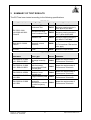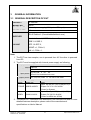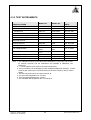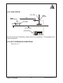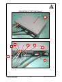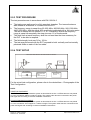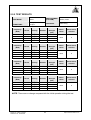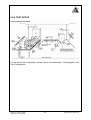
1
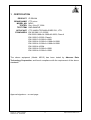
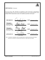
CE EMC TEST REPORT
REPORT NO. : CE951115H04B
MODEL NO. : MD15
RECEIVED : Nov. 27, 2006
TESTED : Dec. 04 to 27, 2006
ISSUED: March 07, 2007
APPLICANT : CTC UNION TECHNOLOGIES CO., LTD.
ADDRESS : 8F, No. 60 ZhouZi St. NeiHu, Taipei 114, Taiwan
ISSUED BY : Advance Data Technology Corporation
LAB LOCATION : No. 81-1, Lu Liao Keng, 9 Ling, Wu Lung Tsuen,
Chiung Lin Hsiang, Hsin Chu Hsien,
Taiwan
This test report consists of 87 pages in total. It may be duplicated completely for legal use with the
approval of the applicant. It should not be reproduced except in full, without the written approval of
our laboratory. The client should not use it to claim product endorsement by CNLA, A2LA or any
government agencies. The test results in the report only apply to the tested sample.
No. 2177-01
Report No.: CE951115H04B
Reference No.: 960305H01
1
Report Format Version 2.0.5
Table of Contents
1
2
2.1
3
3.1
3.2
3.3
3.4
4
4.1
4.1.1
4.1.2
4.1.3
4.1.4
4.1.5
4.1.6
4.1.7
4.2
4.2.1
4.2.2
4.2.3
4.2.4
4.2.5
4.2.6
4.2.7
4.3
4.3.1
4.3.2
4.3.3
4.3.4
4.3.5
4.3.6
4.3.7
4.4
4.4.1
4.4.2
4.4.3
4.4.4
4.4.5
4.4.6
4.5
4.5.1
4.5.2
4.5.3
CERTIFICATION............................................................................................ 4
SUMMARY OF TEST RESULTS.................................................................... 6
MEASUREMENT UNCERTAINTY ..................................................................7
GENERAL INFORMATION ............................................................................ 8
GENERAL DESCRIPTION OF EUT................................................................8
DESCRIPTION OF TEST MODES..................................................................9
GENERAL DESCRIPTION OF APPLIED STANDARDS ...............................10
DESCRIPTION OF SUPPORT UNITS..........................................................11
EMISSION TEST ......................................................................................... 17
CONDUCTED EMISSION MEASUREMENT ................................................17
LIMITS OF CONDUCTED EMISSION MEASUREMENT ..............................17
TEST INSTRUMENTS ..................................................................................17
TEST PROCEDURE .....................................................................................18
DEVIATION FROM TEST STANDARD .........................................................18
TEST SETUP................................................................................................18
EUT OPERATING CONDITIONS..................................................................19
TEST RESULTS............................................................................................20
CONDUCTED EMISSION MEASUREMENT AT TELECOMMUNICATION
PORTS .........................................................................................................24
LIMIT OF CONDUCTED COMMON MODE DISTURBANCE AT
TELECOMMUNICATION PORTS .................................................................24
TEST INSTRUMENTS ..................................................................................24
TEST PROCEDURE .....................................................................................25
DEVIATION FROM TEST STANDARD .........................................................25
TEST SETUP................................................................................................26
EUT OPERATING CONDITIONS..................................................................26
TEST RESULTS............................................................................................27
RADIATED EMISSION MEASUREMENT .....................................................28
LIMITS OF RADIATED EMISSION MEASUREMENT ...................................28
TEST INSTRUMENTS ..................................................................................29
TEST PROCEDURE .....................................................................................30
DEVIATION FROM TEST STANDARD .........................................................30
TEST SETUP................................................................................................31
EUT OPERATING CONDITIONS..................................................................31
TEST RESULTS............................................................................................32
HARMONICS CURRENT MEASUREMENT .................................................36
LIMITS OF HARMONICS CURRENT MEASUREMENT ...............................36
TEST INSTRUMENTS ..................................................................................36
TEST PROCEDURE .....................................................................................37
TEST SETUP................................................................................................38
EUT OPERATING CONDITIONS..................................................................38
TEST RESULTS............................................................................................39
VOLTAGE FLUCTUATION AND FLICKER MEASUREMENT .......................40
LIMITS OF VOLTAGE FLUCTUATION AND FLICKER MEASUREMENT .....40
TEST INSTRUMENTS ..................................................................................40
TEST PROCEDURE .....................................................................................40
Report No.: CE951115H04B
Reference No.: 960305H01
2
Report Format Version 2.0.5
4.5.4
4.5.5
4.5.6
5
5.1
5.2
5.3
5.4
5.4.1
5.4.2
5.4.3
5.4.4
5.4.5
5.5
5.5.1
5.5.2
5.5.3
5.5.4
5.5.5
5.6
5.6.1
5.6.2
5.6.3
5.6.4
5.6.5
5.7
5.7.1
5.7.2
5.7.3
5.7.4
5.7.5
5.8
5.8.1
5.8.2
5.8.3
5.8.4
5.8.5
6
7
TEST SETUP................................................................................................41
EUT OPERATING CONDITIONS..................................................................41
TEST RESULTS............................................................................................42
IMMUNITY TEST ......................................................................................... 43
GENERAL DESCRIPTION............................................................................43
GENERAL PERFORMANCE CRITERIA DESCRIPTION..............................44
EUT OPERATING CONDITION ....................................................................44
ELECTROSTATIC DISCHARGE IMMUNITY TEST (ESD)............................45
TEST SPECIFICATION.................................................................................45
TEST INSTRUMENTS ..................................................................................45
TEST PROCEDURE .....................................................................................45
TEST SETUP................................................................................................47
TEST RESULTS............................................................................................48
RADIATED, RADIO-FREQUENCY, ELECTROMAGNETIC FIELD IMMUNITY
TEST (RS) ....................................................................................................52
TEST SPECIFICATION.................................................................................52
TEST INSTRUMENTS ..................................................................................52
TEST PROCEDURE .....................................................................................53
TEST SETUP................................................................................................53
TEST RESULTS............................................................................................54
ELECTRICAL FAST TRANSIENT/BURST IMMUNITY TEST (EFT) ..............56
TEST SPECIFICATION.................................................................................56
TEST INSTRUMENTS ..................................................................................56
TEST PROCEDURE .....................................................................................56
TEST SETUP................................................................................................57
TEST RESULTS............................................................................................58
SURGE IMMUNITY TEST ............................................................................60
TEST SPECIFICATION.................................................................................60
TEST INSTRUMENTS ..................................................................................60
TEST PROCEDURE .....................................................................................61
TEST SETUP................................................................................................62
TEST RESULTS............................................................................................63
IMMUNITY TO CONDUCTED DISTURBANCES INDUCED BY RF FIELDS
(CS) ..............................................................................................................65
TEST SPECIFICATION.................................................................................65
TEST INSTRUMENTS ..................................................................................65
TEST PROCEDURE .....................................................................................66
TEST SETUP................................................................................................67
TEST RESULTS............................................................................................68
PHOTOGRAPHS OF THE TEST CONFIGURATION................................... 70
APPENDIX - INFORMATION ON THE TESTING LABORATORIES ............ 87
Report No.: CE951115H04B
Reference No.: 960305H01
3
Report Format Version 2.0.5
1 CERTIFICATION
Reference No
PRODUCT:
BRAND NAME:
MODEL NO:
TESTED:
TEST ITEM:
APPLICANT:
STANDARDS:
IP DSLAM
CTC union
MD15
Dec. 04 to 27, 2006
R&D SAMPLE
CTC UNION TECHNOLOGIES CO., LTD.
EN 300 386 V1.3.3:2005
EN 55022:1998+A1:2000+A2:2003, Class A
EN 61000-3-2:2000, Class A
EN 61000-3-3:1995+A1:2001
EN 61000-4-2:1995+A1:1998+A2:2001
EN 61000-4-3:1996+A1:1998+A2:2001
EN 61000-4-4:2004
EN 61000-4-5:1995+A1:2001
EN 61000-4-6:1996+A1:2001
The above equipment (Model: MD15) has been tested by Advance Data
Technology Corporation, and found compliance with the requirement of the above
standards.
Approval signature – on next page
Report No.: CE951115H04B
Reference No.: 960305H01
4
Report Format Version 2.0.5
CERTIFICATION - Continued
The test record, data evaluation & Equipment Under Test (EUT) configurations
represented herein are true and accurate accounts of the measurements of the
sample’s EMC characteristics under the conditions specified in this report.
PREPARED BY
:
,
DATE:
March 07, 2007
,
DATE:
March 07, 2007
,
DATE:
March 07, 2007
,
DATE:
March 07, 2007
( Carol Liao )
TECHNICAL
ACCEPTANCE
:
Responsible for EMI
TECHNICAL
ACCEPTANCE
( Mike Hsieh )
:
Responsible for EMS
APPROVED BY
(Ray Yeh )
:
( Ivan Peng )
Note *: The power consumption of EUT is 29.16W, which is less than 75W and no limits apply.
Therefore it is deemed to comply with EN 61000-3-2: 2000 without any testing.
Report No.: CE951115H04B
Reference No.: 960305H01
5
Report Format Version 2.0.5
2 SUMMARY OF TEST RESULTS
The EUT has been tested according to the following specifications:
Standard
EMISSION
Test Type
Result
Conducted Test
PASS
Telecommunication
Ports Conducted Test
PASS
Radiated Test
PASS
EN61000-3-2:2000,
Class A
Harmonic current
emissions
PASS
EN61000-3-3:1995 +
A1:2001
Voltage fluctuations &
flicker
PASS
Standard
IMMUNITY
Test Type
Result
EN 55022:1998
+A1:2000+A2:2003
,Class B
EN 61000-4-2:1995
+A1:1998+A2:2001
EN 61000-4-3:1996
+A1:1998+A2:2001
EN 61000-4-4:2004
Electrostatic
discharge immunity
test
Radiated,
radio-frequency,
electromagnetic field
immunity test
Electrical fast
transient / burst
immunity test.
Remarks
Meets Class A Limit
Minimum passing margin is
-0.44 dB at 0.615 MHz
Meets Class A Limit
Minimum passing margin is
-18.77 dB at 0.240 MHz
Meets Class A Limit
Minimum passing margin is
-2.3 dB at 177.40 MHz
The power consumption of
EUT is less than 75W and no
limits apply
Meets the requirements.
Remarks
PASS
Meets the requirements of
Performance Criterion A
PASS
Meets the requirements of
Performance Criterion A
PASS
Meets the requirements of
Performance Criterion B
EN 61000-4-5:1995
+A1:2001
Surge immunity test
PASS
Meets the requirements of
Performance Criterion B
EN 61000-4-6:1996
+A1:2001
Immunity to
conducted
disturbances, induced
by radio-frequency
fields
PASS
Meets the requirements of
Performance Criterion A
Report No.: CE951115H04B
Reference No.: 960305H01
6
Report Format Version 2.0.5
2.1 MEASUREMENT UNCERTAINTY
Where relevant, the following measurement uncertainty levels have been estimated
for tests performed on the EUT as specified in CISPR 16-4:
This uncertainty represents an expanded uncertainty expressed at approximately the
95% confidence level using a coverage factor of k=2.
Measurement
Conducted emissions
Radiated emissions (30MHz-1GHz)
Report No.: CE951115H04B
Reference No.: 960305H01
Value
2.53 dB
3.46 dB
7
Report Format Version 2.0.5
3
GENERAL INFORMATION
3.1 GENERAL DESCRIPTION OF EUT
PRODUCT
MODEL NO.
IP DSLAM
MD15
POWER SUPPLY Internal power supply (AC input or DC input)
POWER CORD
NA
DATA CABLE
SUPPLIED
RJ-45 Cable x1 (10cm/shelded/without core)
Line interface x 2, POTS Interface x 2,
GBE 1 & GBE 2,
SFP 1 & SFP 2,
I/O PORT
MGMT x 1, FAN x 2,
HK x1, COM x 1,
Note:
1. The EUT has two samples, one is powered from AC the other is powered
from DC.
2. The EUT must be supplied with Internal power supply as following:
AC input power supply information:
Brand: SINPRO
Model No.: SBU120-246
Input power :
AC110~240 V 63
Hz
3Pins 2.5m Unshielded w/o core
Output power : DC 3.3V 15A 110W
& DC 20.5V 3A 110W
DC input power supply information:
Brand
Model No.
P-DUKE QBE50-48S3P3
Spec.
Input: DC-48(-36~-75)V or 48(36~75)V
Output: DC 3.3V 15 A 49.5W
(Power for System)
ACBEL
SV48-24-100-6
Input: DC-48(-36~-75)V or 48(36~75)V
Output: DC 20.5V/ 4A 96W
(Power for ADSL line & FAN)
3. The above EUT information was declared by the manufacturer and for more
detailed features description, please refer to the manufacturer's
specifications or User's Manual.
Report No.: CE951115H04B
Reference No.: 960305H01
8
Report Format Version 2.0.5
3.2 DESCRIPTION OF TEST MODES
The EUT was tested under the following test modes, and its data were
recorded in this report:
Test Mode
Description
Mode 1
Sample 1: Powered from AC
Mode 2
Sample 2: Powered from DC
For Harmonic current emissions and Voltage fluctuations & flicker test items only
test Mode 1 have been tested.
.
Report No.: CE951115H04B
Reference No.: 960305H01
9
Report Format Version 2.0.5
3.3 GENERAL DESCRIPTION OF APPLIED STANDARDS
The EUT is a kind of telecommunication equipment and, according to the
specifications of the manufacturers, must comply with the requirements of the
following standards:
EN300 386 V1.3.3:2005
EN 55022:1998+A1:2000+A2:2003, Class A
EN 61000-3-2:2000, Class A
EN 61000-3-3:1995+A1: 2001
EN 61000-4-2:1995+A1:1998+A2:2001
EN 61000-4-3:1996+A1:1998+A2:2001
EN 61000-4-4:2004
EN 61000-4-5:1995+A1:2001
EN 61000-4-6:1996+A1:2001
All tests have been performed and recorded as per the above standards.
Report No.: CE951115H04B
Reference No.: 960305H01
10
Report Format Version 2.0.5
3.4 DESCRIPTION OF SUPPORT UNITS
The EUT has been tested as an independent unit together with other necessary
accessories or support units. The following support units or accessories were used to
form a representative test configuration during the tests.
Conducted and Radiated test
No. Product
PERSONAL
1 COMPUTER
Brand
Model No.
Serial No.
FCC ID
HP
DX6120MT
SG5190992H
DoC
2 MONITOR
DELL
2001FP
3 KEYBOARD
BTC
KB-5200T
4 MOUSE
BTC
M851
5 ADSL
6 ADSL
CN-0C0647-46633-58R
DoC
-2W4L
E5XKB5122WT
F24800406
H0110
G00347024432
DoC
Brasi Telecom GS-R2503
G32RG3-017284
NA
XAVI
X8121r
A811A4003409
NA
7
NOTEBOOK
COMPUTER
DELL
PP01L
TW-0791UH-12800-0C
DoC
K-3735
8
NOTEBOOK
COMPUTER
DELL
PPT
17044664176
E2K24GBRL
7700087
NA
DC POWER
9 SUPPLY (only for
DC Mode)
GOOD WILL
INSTRUMEN GPC-3030D
T CO., LTD.
Harmonics Current / Voltage Fluctuation and Flicker / Immunity test
No. Product
Brand
Model No.
Serial No.
FCC ID
1 ADSL
Brasi Telecom GS-R2503
G32RG3-017284
NA
2 ADSL
THOMSON
DSLBA604NP
CP0508GGYZQ
NA
NOTEBOOK
3
COMPUTER
DELL
INSPIRON
5000e
DS/N
TW-054UGW-12961-0B DoC
R-0670
NOTEBOOK
COMPUTER
DELL
PP01L
TW-09C748-12800-17Q
DoC
-C504
4
DC POWER
5 SUPPLY (only for
DC Mode)
Report No.: CE951115H04B
Reference No.: 960305H01
GOOD WILL
INSTRUMEN GPC-3030D
T CO., LTD.
11
7700087
NA
Report Format Version 2.0.5
Conducted and Radiated test
No. Signal cable description
1 NA
2 1.8 m braid shielded wire, terminated with VGA connector via metallic frame, w/o core
3 1.7 m foil shielded wire, terminal by frame, PS2 Connector, w/o core.
4 1.5 m foil shielded wire, terminated with PS2 connector via drain wire, w/o core.
5 NA
6 NA
7 NA
8 NA
9 NA
Harmonics Current / Voltage Fluctuation and Flicker / Immunity test
No. Signal cable description
1 NA
2 NA
3 NA
4 NA
5 NA
Note: 1. All power cords of the above support units are unshielded (1.8m).
Report No.: CE951115H04B
Reference No.: 960305H01
12
Report Format Version 2.0.5
For Conducted and Radiated test (AC Mode):
STP cable (1m), Loop
STP cable (10cm), Loop
POTS cable (1m)
POTS cable (1m)
Line cable (10m)
STP cable (1m)
STP cable (1m)
150 Ohm
150 Ohm
600 Ohm
EUT
600 Ohm
600 Ohm
TEST TABLE
Line Cable (10m)
RJ11 Cable (10m)
UTP Cable (10m)
2. MONITOR
1. PERSONAL
COMPUTER
3. KEYBOARD
4. MOUSE
5. ADSL
7. NOTEBOOK
COMPUTER
6. ADSL
8. NOTEBOOK
COMPUTER
CONTROL ROOM
NOTE: 1. Support units 1-8 were kept in the control room during the test.
2. Please refer to the photos of test configuration in Item 6 also.
Report No.: CE951115H04B
Reference No.: 960305H01
13
Report Format Version 2.0.5
For Conducted and Radiated test (DC Mode):
STP cable (1m), Loop
STP cable (10cm), Loop
POTS cable (1m)
POTS cable (1m)
Line cable (10m)
STP cable (1m)
STP cable (1m)
150 Ohm
150 Ohm
EUT
600 Ohm
600 Ohm
600 Ohm
DC LINE (1m)
TEST TABLE
9. POWER SUPPLY
Line Cable (10m)
RJ11 Cable (10m)
2. MONITOR
3. KEYBOARD
1. PERSONAL
COMPUTER
5. ADSL
7. NOTEBOOK
COMPUTER
4. MOUSE
6. ADSL
8. NOTEBOOK
COMPUTER
CONTROL ROOM
NOTE: 1. Support units 1-8 were kept in the control room during the test.
2. Please refer to the photos of test configuration in Item 6 also.
Report No.: CE951115H04B
Reference No.: 960305H01
14
Report Format Version 2.0.5
For Harmonics Current / Voltage Fluctuation and Flicker / Immunity test (AC Mode):
STP cable (1m), Loop
STP cable (10cm), Loop
POTS cable (1m)
POTS cable (1m)
Line cable (10m)
STP cable (1m)
STP cable (1m)
150 Ohm
150 Ohm
600 Ohm
EUT
600 Ohm
600 Ohm
STP cable (1m)
TEST TABLE
150 Ohm
Line Cable (10m)
RJ11 Cable (10m)
1. ADSL
3. NOTEBOOK
COMPUTER
CONTROL ROOM
2. ADSL
4. NOTEBOOK
COMPUTER
NOTE: 1. Support units 1-4 were kept in the control room during the test.
2. Please refer to the photos of test configuration in Item 6 also.
Report No.: CE951115H04B
Reference No.: 960305H01
15
Report Format Version 2.0.5
For Immunity test (DC Mode):
STP cable (1m), Loop
STP cable (10cm), Loop
POTS cable (1m)
POTS cable (1m)
Line cable (10m)
STP cable (1m)
STP cable (1m)
150 Ohm
150 Ohm
600 Ohm
EUT
600 Ohm
DC LINE (1m)
STP cable (1m)
TEST TABLE
600 Ohm
150 Ohm
5. POWER SUPPLY
Line Cable (10m)
RJ11 Cable (10m)
1. ADSL
3. NOTEBOOK
COMPUTER
CONTROL ROOM
2. ADSL
4. NOTEBOOK
COMPUTER
NOTE: 1. Support units 1-4 were kept in the control room during the test.
2. Please refer to the photos of test configuration in Item 6 also.
Report No.: CE951115H04B
Reference No.: 960305H01
16
Report Format Version 2.0.5
4
EMISSION TEST
4.1 CONDUCTED EMISSION MEASUREMENT
4.1.1 LIMITS OF CONDUCTED EMISSION MEASUREMENT
FREQUENCY (MHz)
0.15 - 0.5
0.50 - 5.0
5.0 - 30.0
NOTE:
Class A (dBuV)
Quasi-peak Average
79
66
73
60
73
60
Class B (dBuV)
Quasi-peak Average
66 - 56
56 - 46
56
46
60
50
(1) The lower limit shall apply at the transition frequencies.
(2) The limit decreases in line with the logarithm of the frequency in the range of 0.15
to 0.50 MHz.
(3) All emanations from a class A/B digital device or system, including any network of
conductors and apparatus connected thereto, shall not exceed the level of field
strengths specified above.
4.1.2 TEST INSTRUMENTS
DESCRIPTION &
MANUFACTURER
MODEL NO.
SERIAL NO.
CALIBRATED
UNTIL
ROHDE & SCHWARZ
Test Receiver
ESCS 30
100287
Feb. 20, 2007
Line-Impedance Stabilization
Network(for EUT)
ENV-216
100072
Oct. 26, 2007
Line-Impedance Stabilization
Network(for Peripheral)
ESH3-Z5
848773/004
Oct. 26, 2007
RF Cable (JETBAO)
RG233/U
Cable_CA_01
Jul. 19, 2007
Terminator
50
1
Oct. 30, 2007
Software
ADT_Cond_V7.3.2
NA
NA
NOTE: 1. The calibration interval of the above test instruments is 12 months and the calibrations
are traceable to NML/ROC and NIST/USA.
2. The test was performed in ADT Shielded Room No. A.
3. The VCCI Con A Registration No. is C-817.
Report No.: CE951115H04B
Reference No.: 960305H01
17
Report Format Version 2.0.5
4.1.3 TEST PROCEDURE
a. The EUT was placed 0.4 meters from the conducting wall of the shielded room
with EUT being connected to the power mains through a line impedance
stabilization network (LISN). Other support units were connected to the power
mains through another LISN. The two LISNs provide 50 Ohm/ 50uH of coupling
impedance for the measuring instrument.
b. Both lines of the power mains connected to the EUT were checked for maximum
conducted interference.
c. The frequency range from 150 kHz to 30 MHz was searched. Emission levels over
10dB under the prescribed limits could not be reported.
4.1.4 DEVIATION FROM TEST STANDARD
No deviation
4.1.5 TEST SETUP
Ve r tic a l R e fe r e n c e
G r o u n d P la n e
Te s t R e c e iv e r
EUT
40cm
80cm
L IS N
H o r iz o n ta l R e fe r e n c e
G ro u n d P la n e
N o te : 1 .S u p p o r t u n its w e r e c o n n e c te d to s e c o n d L IS N .
2 .B o th o f L IS N s ( A M N ) a r e 8 0 c m fr o m E U T a n d a t le a s t 8 0
fr o m o th e r u n its a n d o th e r m e ta l p la n e s
For the actual test configuration, please refer to the related item – Photographs of the
Test Configuration.
Report No.: CE951115H04B
Reference No.: 960305H01
18
Report Format Version 2.0.5
4.1.6 EUT OPERATING CONDITIONS
1.
2.
3.
Turn on the power of all equipment.
Prepared other computer systems (support units 1-8) to act as
communication partners and placed them outside of testing area.
The computer systems (support units 7 and 8) run “ping.exe” and
“TfGen.exe” test program to enable EUT under transmission/receiving
condition continuously via line cable and RJ11 cables.
Report No.: CE951115H04B
Reference No.: 960305H01
19
Report Format Version 2.0.5
4.1.7 TEST RESULTS
TEST MODE
Mode 1
PHASE
Line (L)
INPUT POWER
230Vac, 50 Hz
6dB BANDWIDTH
9 kHz
ENVIRONMENTAL
CONDITIONS
25 deg. C, 60 % RH,
965 hPa
TESTED BY
Eason Chang
Freq.
Corr.
Reading Value
[MHz]
0.240
0.482
1.611
2.525
7.887
12.254
Factor
(dB)
9.80
9.81
9.90
9.90
9.96
10.09
[dB (uV)]
Q.P.
AV.
46.46
42.69
36.64
32.80
28.74
43.00
-
No
1
2
3
4
5
6
Emission
Level
[dB (uV)]
Q.P.
AV.
56.26
52.50
46.54
42.70
38.70
53.09
-
Limit
Margin
[dB (uV)]
Q.P.
AV.
79.00 66.00
79.00 66.00
73.00 60.00
73.00 60.00
73.00 60.00
73.00 60.00
(dB)
Q.P.
-22.74
-26.50
-26.46
-30.30
-34.30
-19.91
AV.
-
REMARKS: 1. Q.P. and AV. are abbreviations of quasi-peak and average individually.
2. "-": The Quasi-peak reading value also meets average limit and
measurement with the average detector is unnecessary.
3. The emission levels of other frequencies were very low against the limit.
4. Margin value = Emission level - Limit value
5. Correction factor = Insertion loss + Cable loss
6. Emission Level = Correction Factor + Reading Value.
Report No.: CE951115H04B
Reference No.: 960305H01
20
Report Format Version 2.0.5
TEST MODE
Mode 1
PHASE
Neutral (N)
INPUT POWER
230Vac, 50 Hz
6dB BANDWIDTH
9 kHz
ENVIRONMENTAL
CONDITIONS
25 deg. C, 60 % RH,
965 hPa
TESTED BY
Eason Chang
Freq.
Corr.
Reading Value
[MHz]
0.240
0.513
1.451
1.935
2.584
12.256
Factor
(dB)
9.80
9.82
9.95
9.99
10.00
10.19
[dB (uV)]
Q.P.
AV.
49.99
43.43
41.58
39.91
38.38
45.01
-
No
1
2
3
4
5
6
Emission
Level
[dB (uV)]
Q.P.
AV.
59.79
53.25
51.53
49.90
48.38
55.20
-
Limit
Margin
[dB (uV)]
Q.P.
AV.
79.00 66.00
73.00 60.00
73.00 60.00
73.00 60.00
73.00 60.00
73.00 60.00
(dB)
Q.P.
-19.21
-19.75
-21.47
-23.10
-24.62
-17.80
AV.
-
REMARKS: 1. Q.P. and AV. are abbreviations of quasi-peak and average individually.
2. "-": The Quasi-peak reading value also meets average limit and
measurement with the average detector is unnecessary.
3. The emission levels of other frequencies were very low against the limit.
4. Margin value = Emission level - Limit value
5. Correction factor = Insertion loss + Cable loss
6. Emission Level = Correction Factor + Reading Value.
Report No.: CE951115H04B
Reference No.: 960305H01
21
Report Format Version 2.0.5
TEST MODE
Mode 2
PHASE
Positive
INPUT POWER
DC 48V
6dB BANDWIDTH
9 kHz
ENVIRONMENTAL
CONDITIONS
25deg. C, 60%RH,
TESTED BY
Timmy Hu
Freq.
Corr.
Reading Value
[MHz]
0.374
0.614
0.749
2.420
10.096
21.683
Factor
(dB)
9.80
9.84
9.86
9.90
10.00
10.13
[dB (uV)]
Q.P.
AV.
50.41
49.62
46.71
45.41
45.43
45.64
-
No
1
2
3
4
5
6
965hPa
Emission
Level
[dB (uV)]
Q.P.
AV.
60.21
59.46
56.57
55.31
55.43
55.77
-
Limit
Margin
[dB (uV)]
Q.P.
AV.
79.00 66.00
73.00 60.00
73.00 60.00
73.00 60.00
73.00 60.00
73.00 60.00
(dB)
Q.P.
-18.79
-13.54
-16.43
-17.69
-17.57
-17.23
AV.
-
REMARKS: 1. Q.P. and AV. are abbreviations of quasi-peak and average individually.
2. "-": The Quasi-peak reading value also meets average limit and
measurement with the average detector is unnecessary.
3. The emission levels of other frequencies were very low against the limit.
4. Margin value = Emission level - Limit value
5. Correction factor = Insertion loss + Cable loss
6. Emission Level = Correction Factor + Reading Value.
Report No.: CE951115H04B
Reference No.: 960305H01
22
Report Format Version 2.0.5
TEST MODE
Mode 2
PHASE
Negative
INPUT POWER
DC 48V
6dB BANDWIDTH
9 kHz
ENVIRONMENTAL
CONDITIONS
25deg. C, 60%RH,
TESTED BY
Timmy Hu
Freq.
Corr.
Reading Value
[MHz]
0.374
0.615
0.752
2.420
10.096
21.723
Factor
(dB)
9.80
9.84
9.86
10.00
10.10
10.43
[dB (uV)]
Q.P.
AV.
50.41
50.62 49.72
48.81
46.41
48.43
46.64
-
No
1
2
3
4
5
6
965hPa
Emission
Level
[dB (uV)]
Q.P.
AV.
60.21
60.46 59.56
58.67
56.41
58.53
57.07
-
Limit
Margin
[dB (uV)]
Q.P.
AV.
79.00 66.00
73.00 60.00
73.00 60.00
73.00 60.00
73.00 60.00
73.00 60.00
(dB)
Q.P.
AV.
-18.79
-12.54
-0.44
-14.33
-16.59
-14.47
-15.93
-
REMARKS: 1. Q.P. and AV. are abbreviations of quasi-peak and average individually.
2. "-": The Quasi-peak reading value also meets average limit and
measurement with the average detector is unnecessary.
3. The emission levels of other frequencies were very low against the limit.
4. Margin value = Emission level - Limit value
5. Correction factor = Insertion loss + Cable loss
6. Emission Level = Correction Factor + Reading Value.
Report No.: CE951115H04B
Reference No.: 960305H01
23
Report Format Version 2.0.5
4.2 CONDUCTED EMISSION MEASUREMENT AT
TELECOMMUNICATION PORTS
4.2.1 LIMIT OF CONDUCTED COMMON MODE DISTURBANCE AT
TELECOMMUNICATION PORTS
FOR CLASS A EQUIPMENT
FREQUENCY
(MHz)
0.15 - 0.5
0.5 - 30.0
Voltage Limit (dBuV)
Quasi-peak
Average
97 - 87
84 - 74
87
74
Current Limit (dBuA)
Quasi-peak
Average
53 - 43
40 - 30
43
30
FOR CLASS B EQUIPMENT
FREQUENCY
(MHz)
0.15 - 0.5
0.5 - 30.0
NOTE: (1)
Voltage Limit (dBuV)
Quasi-peak
Average
84 - 74
74 - 64
74
64
Current Limit (dBuA)
Quasi-peak
Average
40 - 30
30 - 20
30
20
The limits decrease linearly with the logarithm of the frequency in the range
0.15 MHz to 0.5 MHz.
4.2.2 TEST INSTRUMENTS
DESCRIPTION &
MANUFACTURER
MODEL NO.
SERIAL NO.
CALIBRATED
UNTIL
ROHDE & SCHWARZ
Test Receiver
ESCS 30
100287
Feb. 10, 2007
Line-Impedance Stabilization
Network(for EUT)
ENV-216
100072
Oct. 26, 2007
ESH3-Z5
848773/004
Oct. 20, 2007
ENY 41
ENY 22
838119/024
837497/019
RG233/U
SMZ 11
F-35
CVP 2200
KEMA 801
Cable_CA_01
18001
455
18312
16617
Feb. 24, 2007
Feb. 24, 2007
Jul. 18, 2007
Jul. 25, 2007
Jul. 04, 2007
Jul. 25, 2007
NA
Line-Impedance Stabilization
Network(for Peripheral)
ROHDE & SCHWARZ ISN
ROHDE & SCHWARZ ISN
RF Cable (JETBAO)
CURRENT PROBE
RF Current Probe
Capacitive Voltage Probe
RF- ABSORBING CLAMP
NOTE: 1. The calibration interval of the above test instruments is 12 months and the calibrations
are traceable to NML/ROC and NIST/USA.
4. The test was performed in ADT Shielded Room No. A.
5. The VCCI Con A Registration No. is C-817.
Report No.: CE951115H04B
Reference No.: 960305H01
24
Report Format Version 2.0.5
4.2.3 TEST PROCEDURE
a. The EUT was placed 0.4 meters from the conducting wall of the shielded room
and connected to the power mains through a line impedance stabilization
network (LISN). Other support units were connected to the power mains through
another LISN.
b. Current at the measurement port of the ISN was detected, the reading was
corrected by adding the current division factor of the ISN, and was compared to
the current limits.
c. The disturbance levels and the frequencies of at least six highest disturbances
were recorded from each telecommunication port which comprises the EUT.
4.2.4 DEVIATION FROM TEST STANDARD
No deviation
Report No.: CE951115H04B
Reference No.: 960305H01
25
Report Format Version 2.0.5
4.2.5 TEST SETUP
Test
Receiver
EUT
AE
10 cm
1)
Current probe
40 cm
2)
ISN/CDN
30 cm to 80 cm
1) Distance to the reference ground plane (vertical or horizontal).
2) Distance to the reference ground plane is not critical.
For the actual test configuration, please refer to the related item – Photographs of the Test
Configuration.
4.2.6 EUT OPERATING CONDITIONS
Same as 4.1.6.
Report No.: CE951115H04B
Reference No.: 960305H01
26
Report Format Version 2.0.5
4.2.7 TEST RESULTS
INPUT POWER
(SYSTEM)
230Vac, 50Hz
TELECOM PORT
RJ11( to ADSL)
ENVIRONMENTAL
CONDITIONS
25 deg. C, 60% RH,
965 hPa
Freq.
Corr.
[MHz]
0.240
0.361
0.662
1.084
1.505
1.925
Factor
(dB)
10.13
10.15
10.17
10.17
10.20
10.22
No
1
2
3
4
5
6
REMARKS:
Reading
Value
[dB (uV)]
Q.P.
AV.
64.19
57.37
55.55
57.17
54.19
55.42
-
6dB BANDWIDTH 9 kHz
TESTED BY : Eason Chang
Emission
Level
[dB (uV)]
Q.P.
AV.
74.32
67.52
65.72
67.34
64.39
65.64
-
Limit
Margin
[dB (uV)]
Q.P.
A.V.
93.09 80.09
89.71 76.71
87.00 74.00
87.00 74.00
87.00 74.00
87.00 74.00
(dB)
Q.P.
A.V.
-18.77
-22.19
-21.28
-19.66
-22.61
-21.36
-
1. Q.P. and AV. are abbreviations of quasi-peak and average individually.
2. "-": The Quasi-peak reading value also meets average limit and
measurement with the average detector is unnecessary.
3. The emission levels of other frequencies were very low against the limit.
4. Margin value = Emission level - Limit value
5. Correction factor = Insertion loss + Cable loss
6. Emission Level = Correction Factor + Reading Value.
Report No.: CE951115H04B
Reference No.: 960305H01
27
Report Format Version 2.0.5
4.3
RADIATED EMISSION MEASUREMENT
4.3.1 LIMITS OF RADIATED EMISSION MEASUREMENT
FREQUENCY (MHz)
30 - 230
230 - 1000
NOTE:
Class A (at 10m)
dBuV/m
40
47
Class B (at 10m)
dBuV/m
30
37
(1) The lower limit shall apply at the transition frequencies.
(2) Emission level (dBuV/m) = 20 log Emission level (uV/m).
(3) All emanations from a class A/B digital device or system, including any network
of conductors and apparatus connected thereto, shall not exceed the level of field
strengths specified above.
Report No.: CE951115H04B
Reference No.: 960305H01
28
Report Format Version 2.0.5
4.3.2 TEST INSTRUMENTS
DESCRIPTION &
MANUFACTURER
*ADVANTEST Spectrum Analyzer
*HP Pre_Amplifier
*ROHDE & SCHWARZ
Test Receiver
*CHASE Broadband Antenna
*Schwarzbeck Horn_Antenna
Schwarzbeck Horn_Antenna
SCHWARZBECK
Biconical Antenna
SCHWARZBECK
Periodic Antenna
*RF Switches
*RF Cable(CHASE)
*Software
*CHANCE MOST Antenna Tower
*CHANCE MOST Turn Table
*CORCOM AC Filter
MODEL NO.
SERIAL NO.
R3271A
8449B
85060311
3008A01922
CALIBRATED
UNTIL
July 03, 2007
Sep. 18, 2007
ESVS 30
841977/002
Oct. 30, 2007
CBL6111C
BBHA9120-D1
BBHA 9170
2730
D123
BBHA9170153
Jun. 08, 2007
Sep. 25, 2007
Jan. 05, 2007
VHBA9123
459
Jun. 08, 2009
UPA6108
1148
Jun. 08, 2009
MP59B
9913-30M
N-N
Cable
ADT_Radiated_V
5.14
AT-100
TC-008
MRI2030
6100175593
STBCAB-30M-1
GHz
Jul. 17, 2007
NA
NA
CM-A007
CM-T007
024/019
NA
NA
NA
Jul. 17, 2007
Note: 1. The calibration interval of the above test instruments is 12 months (36 months
for Periodic Antenna) and the calibrations are traceable to NML/ROC and
NIST/USA.
2. * = These equipment are used for the final measurement.
3. The horn antenna, HP preamplifier (model: 8449B) and Spectrum Analyzer (model:
R3271A) are used only for the measurement of emission frequency above 1GHz if
tested.
4. The test was performed in ADT Open Site No. B.
5. The VCCI Site Registration No. is R-847.
6. The FCC Site Registration No. is 92753.
7. The CANADA Site Registration No. is IC 4824A-2.
Report No.: CE951115H04B
Reference No.: 960305H01
29
Report Format Version 2.0.5
4.3.3 TEST PROCEDURE
a. The EUT was placed on the top of a rotating table 0.8 meters above the ground
at a 10-meter open field site. The table was rotated 360 degrees to determine the
position of the highest radiation.
b. The EUT was set 10 meters away from the interference-receiving antenna, which
was mounted on the top of a variable-height antenna tower.
c. The antenna is a broadband antenna, and its height is varied from one meter to
four meters above the ground to determine the maximum value of the field
strength. Both horizontal and vertical polarization of the antenna are set to make
the measurement.
d. For each suspected emission, the EUT was arranged to its worst case and then
the antenna was tuned to heights from 1 meter to 4 meters and the turn table
was turned from 0 degrees to 360 degrees to find the maximum reading.
e. The test-receiver system was set to Peak Detect Function and Specified
Bandwidth with Maximum Hold Mode.
f. If the emission level of the EUT in peak mode was 10 dB lower than the limit
specified, then testing could be stopped and the peak values of the EUT would
be reported. Otherwise the emissions that did not have 10 dB margin would be
re-tested one by one using the quasi- peak method or average method as
specified and then reported In Data sheet peak mode and QP mode.
4.3.4 DEVIATION FROM TEST STANDARD
No deviation
Report No.: CE951115H04B
Reference No.: 960305H01
30
Report Format Version 2.0.5
4.3.5 TEST SETUP
Ant. Tower
EUT&
Support Units
1-4m
Variable
10m
Turn Table
80cm
Ground Plane
Test Receiver
For the actual test configuration, please refer to the related item – Photographs of the
Test Configuration.
4.3.6 EUT OPERATING CONDITIONS
Same as 4.1.6
Report No.: CE951115H04B
Reference No.: 960305H01
31
Report Format Version 2.0.5
4.3.7 TEST RESULTS
TEST MODE
Mode 1
INPUT POWER
(SYSTEM)
FREQUENCY RANGE
30-1000 MHz
DETECTOR
FUNCTION &
BANDWIDTH
Quasi-Peak,
ENVIRONMENTAL
CONDITIONS
24 deg. C, 60 % RH,
965 hPa
TESTED BY
Max Tseng
230Vac, 50Hz
120kHz
ANTENNA POLARITY & TEST DISTANCE: HORIZONTAL AT 10 M
No.
Freq.
(MHz)
1
2
3
4
5
6
7
8
9
10
50.80
125.00
172.63
177.40
221.94
380.80
666.66
750.00
875.00
999.99
REMARKS:
Emission
Level
(dBuV/m)
31.20 QP
33.50 QP
33.50 QP
37.70 QP
30.10 QP
38.10 QP
38.10 QP
37.50 QP
37.50 QP
41.70 QP
Limit
(dBuV/m)
Margin
(dB)
40.00
40.00
40.00
40.00
40.00
47.00
47.00
47.00
47.00
47.00
-8.80
-6.50
-6.50
-2.30
-9.90
-8.90
-8.90
-9.50
-9.50
-5.30
Antenna
Height
(m)
4.00 H
4.00 H
4.00 H
4.00 H
4.00 H
1.88 H
1.33 H
1.17 H
1.00 H
1.00 H
Table
Angle
(Degree)
109
267
85
153
316
0
306
124
216
308
Raw
Value
(dBuV)
20.80
20.90
22.40
26.90
17.40
18.90
13.00
10.10
8.50
12.10
Correction
Factor
(dB/m)
10.40
12.60
11.10
10.80
12.70
19.10
25.20
27.40
29.00
29.50
1. Emission level(dBuV/m)=Raw Value(dBuV) + Correction Factor(dB/m)
2. Correction Factor(dB/m) = Antenna Factor (dB/m) + Cable Factor (dB)
3. The other emission levels were very low against the limit.
4. Margin value = Emission level – Limit value.
Report No.: CE951115H04B
Reference No.: 960305H01
32
Report Format Version 2.0.5
TEST MODE
Mode 1
INPUT POWER
(SYSTEM)
FREQUENCY RANGE
30-1000 MHz
DETECTOR
FUNCTION &
BANDWIDTH
Quasi-Peak,
ENVIRONMENTAL
CONDITIONS
24 deg. C, 60 % RH,
965 hPa
TESTED BY
Max Tseng
230Vac, 50Hz
120kHz
ANTENNA POLARITY & TEST DISTANCE: VERTICAL AT 10 M
No.
Freq.
(MHz)
1
2
3
4
5
6
7
8
9
10
50.00
125.00
150.00
172.63
177.36
371.30
666.66
750.00
875.00
999.99
REMARKS:
Emission
Level
(dBuV/m)
34.50 QP
33.80 QP
28.40 QP
37.50 QP
36.50 QP
35.20 QP
36.10 QP
37.20 QP
37.10 QP
37.10 QP
Limit
(dBuV/m)
Margin
(dB)
40.00
40.00
40.00
40.00
40.00
47.00
47.00
47.00
47.00
47.00
-5.50
-6.20
-11.60
-2.50
-3.50
-11.80
-10.90
-9.80
-9.90
-9.90
Antenna
Height
(m)
1.01 V
1.01 V
1.01 V
1.01 V
1.01 V
1.01 V
2.22 V
2.10 V
2.00 V
1.90 V
Table
Angle
(Degree)
216
291
267
27
29
91
4
144
197
0
Raw
Value
(dBuV)
23.90
21.20
15.70
26.40
25.70
16.50
11.00
9.80
8.20
7.60
Correction
Factor
(dB/m)
10.60
12.60
12.70
11.10
10.80
18.70
25.20
27.40
29.00
29.50
1. Emission level(dBuV/m)=Raw Value(dBuV) + Correction Factor(dB/m)
2. Correction Factor(dB/m) = Antenna Factor (dB/m) + Cable Factor (dB)
3. The other emission levels were very low against the limit.
4. Margin value = Emission level – Limit value.
Report No.: CE951115H04B
Reference No.: 960305H01
33
Report Format Version 2.0.5
TEST MODE
Mode 2
INPUT POWER
(SYSTEM)
FREQUENCY RANGE
30-1000 MHz
DETECTOR
FUNCTION &
BANDWIDTH
Quasi-Peak,
ENVIRONMENTAL
CONDITIONS
26 deg. C, 60 % RH,
965 hPa
TESTED BY
Jerry Fan
DC -48V
120kHz
ANTENNA POLARITY & TEST DISTANCE: HORIZONTAL AT 10 M
No.
Freq.
(MHz)
1
2
3
4
5
6
7
8
9
10
11
12
125.00
151.98
228.13
250.00
300.00
375.00
399.99
500.00
624.99
749.99
874.99
999.99
REMARKS:
Emission
Level
(dBuV/m)
26.50 QP
31.80 QP
32.40 QP
33.10 QP
34.40 QP
36.80 QP
36.90 QP
35.40 QP
31.80 QP
35.30 QP
34.40 QP
37.10 QP
Limit
(dBuV/m)
Margin
(dB)
40.00
40.00
40.00
47.00
47.00
47.00
47.00
47.00
47.00
47.00
47.00
47.00
-13.50
-8.20
-7.60
-13.90
-12.60
-10.20
-10.10
-11.60
-15.20
-11.70
-12.60
-9.90
Antenna
Height
(m)
4.00 H
4.00 H
4.00 H
2.08 H
2.17 H
1.93 H
1.95 H
1.70 H
1.59 H
1.00 H
1.00 H
1.00 H
Table
Angle
(Degree)
1
289
237
49
167
326
16
238
224
200
309
201
Raw
Value
(dBuV)
13.90
19.30
19.20
18.50
17.80
17.90
16.90
12.80
7.00
7.90
5.40
7.50
Correction
Factor
(dB/m)
12.60
12.50
13.10
14.60
16.70
18.90
20.00
22.60
24.80
27.40
29.00
29.50
1. Emission level(dBuV/m)=Raw Value(dBuV) + Correction Factor(dB/m)
2. Correction Factor(dB/m) = Antenna Factor (dB/m) + Cable Factor (dB)
3. The other emission levels were very low against the limit.
4. Margin value = Emission level – Limit value.
Report No.: CE951115H04B
Reference No.: 960305H01
34
Report Format Version 2.0.5
TEST MODE
Mode 2
INPUT POWER
(SYSTEM)
FREQUENCY RANGE
30-1000 MHz
DETECTOR
FUNCTION &
BANDWIDTH
Quasi-Peak,
ENVIRONMENTAL
CONDITIONS
26 deg. C, 60 % RH,
965 hPa
TESTED BY
Jerry Fan
DC -48V
120kHz
ANTENNA POLARITY & TEST DISTANCE: VERTICAL AT 10 M
No.
Freq.
(MHz)
1
2
3
4
5
6
7
8
9
10
11
12
49.58
70.65
124.90
177.36
234.00
300.00
370.30
499.80
624.99
749.99
799.99
999.99
REMARKS:
Emission
Level
(dBuV/m)
29.00 QP
26.10 QP
32.60 QP
27.80 QP
31.20 QP
32.80 QP
35.20 QP
34.80 QP
33.80 QP
33.10 QP
38.20 QP
36.80 QP
Limit
(dBuV/m)
Margin
(dB)
40.00
40.00
40.00
40.00
47.00
47.00
47.00
47.00
47.00
47.00
47.00
47.00
-11.00
-13.90
-7.40
-12.20
-15.80
-14.20
-11.80
-12.20
-13.20
-13.90
-8.80
-10.20
Antenna
Height
(m)
1.00 V
1.00 V
1.00 V
1.00 V
1.00 V
1.00 V
1.00 V
1.00 V
2.98 V
2.38 V
1.94 V
1.87 V
Table
Angle
(Degree)
93
336
270
196
264
277
205
63
233
85
301
25
Raw
Value
(dBuV)
18.20
18.20
20.00
16.90
17.70
16.10
16.60
12.20
9.00
5.70
10.90
7.30
Correction
Factor
(dB/m)
10.80
7.90
12.60
10.80
13.50
16.70
18.70
22.60
24.80
27.40
27.30
29.50
1. Emission level(dBuV/m)=Raw Value(dBuV) + Correction Factor(dB/m)
2. Correction Factor(dB/m) = Antenna Factor (dB/m) + Cable Factor (dB)
3. The other emission levels were very low against the limit.
4. Margin value = Emission level – Limit value.
Report No.: CE951115H04B
Reference No.: 960305H01
35
Report Format Version 2.0.5
4.4 HARMONICS CURRENT MEASUREMENT
4.4.1 LIMITS OF HARMONICS CURRENT MEASUREMENT
Limits for Class A equipment
Harmonics Max. permissible
Order
harmonics current
n
A
Odd harmonics
3
2.30
5
1.14
7
0.77
9
0.40
11
0.33
13
0.21
15<=n<=39 0.15x15/n
Even harmonics
2
1.08
4
0.43
6
0.30
8<=n<=40 0.23x8/n
Harmonics
Order
n
3
5
7
9
11
13
15<=n<=39
Limits for Class D equipment
Max. permissible
Max. permissible
harmonics current per
harmonics current
watt mA/W
A
Odd Harmonics only
3.4
2.30
1.9
1.14
1.0
0.77
0.5
0.40
0.35
0.33
0.30
0.21
3.85/n
0.15x15/n
NOTE: 1. The classifications of equipment are defined in Section 5 of EN 61000-3-2:2000.
2. The above limits for all equipment except for lighting equipment are for all applications
having an active input power > 75 W. No limits apply for equipment with an active input
power up to and including 75 W.
4.4.2 TEST INSTRUMENTS
Description & Manufacturer
EMC PARTNER
EMC Emission Tester
EMC Partner(Software)
Model No.
Serial No.
Calibrated Until
HAR1000
086
Mar. 16, 2007
HARCS_V3.15
NA
NA
NOTE: 1. The calibration interval of the above test instruments is 12 months and the calibrations are
traceable to NML/ROC and NIST/USA.
2. The test was performed in EMS room.
Report No.: CE951115H04B
Reference No.: 960305H01
36
Report Format Version 2.0.5
4.4.3 TEST PROCEDURE
a. The EUT was placed on the top of a wooden table 0.8 meters above the ground
and operated to produce the maximum harmonic components under normal
operating conditions for each successive harmonic component in turn.
b. The classification of EUT is according to section 5 of EN 61000-3-2: 2000.
The EUT is classified as follows:
Class A: Balanced three-phase equipment, Household appliances excluding equipment as
Class D, Tools excluding portable tools, Dimmers for incandescent lamps, audio
equipment, equipment not specified in one of the three other classes.
Class B: Portable tools.; Arc welding equipment which is not professional equipment
Class C: Lighting equipment.
Class D: Equipment having a specified power less than or equal to 600 W of the following
types: Personal computers and personal computer monitors and television
receivers.
c. The correspondent test program of test instrument to measure the current
harmonics emanated from EUT is chosen. The measure time shall be not less
than the time necessary for the EUT to be exercised.
Report No.: CE951115H04B
Reference No.: 960305H01
37
Report Format Version 2.0.5
4.4.4 TEST SETUP
EUT
For the actual test configuration, please refer to the related item – Photographs of the
Test Configuration.
4.4.5 EUT OPERATING CONDITIONS
1.
2.
3.
Turn on the power of all equipment.
Prepared other computer systems (support units 1-4) to act as
communication partners and placed them outside of testing area.
The computer systems (support units 3 and 4) run “ping.exe” test program
to enable EUT under transmission/receiving condition continuously via line
cable and RJ11 cables.
Report No.: CE951115H04B
Reference No.: 960305H01
38
Report Format Version 2.0.5
4.4.6 TEST RESULTS
FUNDAMENTAL
VOLTAGE/AMPERE
230.1 Vrms /
0.175 Arms
POWER
FREQUENCY
50.000 Hz
POWER
CONSUMPTION
29.16 W
POWER FACTOR
0.723
ENVIRONMENTAL
CONDITIONS
23 deg. C, 55 % RH,
965 hPa
TESTED BY
Ray Yeh
NOTE: 1. Limits are not specified for equipment with a rated power of 75W or less
(other than lighting equipment).
2. According to EN61000-3-2: 2000 the manufacturer shall specify the power
of the apparatus. This value shall be used for establishing limits. The
specified power shall be within +/-10% of the measured power.
Report No.: CE951115H04B
Reference No.: 960305H01
39
Report Format Version 2.0.5
4.5 VOLTAGE FLUCTUATION AND FLICKER MEASUREMENT
4.5.1 LIMITS OF VOLTAGE FLUCTUATION AND FLICKER
MEASUREMENT
TEST ITEM
Pst
LIMIT
1.0
Pst means short-term flicker indicator.
Plt
0.65
Plt means long-term flicker indicator.
500
Tdt means maximum time that dt
exceeds 3.3 %.
4%
dmax means maximum relative voltage
change.
dc means relative steady-state voltage
change
Tdt (ms)
dmax (%)
dc (%)
3.3%
NOTE
4.5.2 TEST INSTRUMENTS
Description & Manufacturer
EMC PARTNER
EMC Emission Tester
EMC Partner(Software)
Model No.
Serial No.
Calibrated Until
HAR1000
086
Mar. 16, 2007
HARCS_V3.15
NA
NA
NOTE: 1. The calibration interval of the above test instruments is 12 months and the calibrations are
traceable to NML/ROC and NIST/USA.
2. The test was performed in EMS room.
4.5.3
TEST PROCEDURE
a. The EUT was placed on the top of a wooden table 0.8 meters above the ground
and operated to produce the most unfavorable sequence of voltage changes
under normal operating conditions.
b. During the flick measurement, the measure time shall include that part of whole
operation cycle in which the EUT produce the most unfavorable sequence of
voltage changes. The observation period for short-term flicker indicator is 10
minutes and the observation period for long-term flicker indicator is 2 hours.
Report No.: CE951115H04B
Reference No.: 960305H01
40
Report Format Version 2.0.5
4.5.4 TEST SETUP
EUT
For the actual test configuration, please refer to the related item – Photographs of the
Test Configuration.
4.5.5 EUT OPERATING CONDITIONS
1.
2.
3.
Turn on the power of all equipment.
Prepared other computer systems (support units 1-4) to act as
communication partners and placed them outside of testing area.
The computer systems (support units 3 and 4) run “ping.exe” test program
to enable EUT under transmission/receiving condition continuously via line
cable and RJ11 cables.
Report No.: CE951115H04B
Reference No.: 960305H01
41
Report Format Version 2.0.5
4.5.6 TEST RESULTS
FUNDAMENTAL
VOLTAGE/AMPERE
230.1 Vrms /
0.175 Arms
POWER
FREQUENCY
50.013 Hz
OBSERVATION
PERIOD (TP)
10 min.
POWER FACTOR
0.715
ENVIRONMENTAL
CONDITIONS
24 deg. C, 65 % RH,
965 hPa
TESTED BY
Ray Yeh
TEST PARAMETER
MEASUREMENT
VALUE
LIMIT
REMARKS
Pst
0.072
1.00
Pass
Plt
0.072
0.65
Pass
Tdt (ms)
0.00
500
Pass
dmax (%)
0.00
4%
Pass
dc (%)
0.04
3.3%
Pass
NOTE:
(1)
(2)
(3)
(4)
(5)
Pst means short-term flicker indicator.
Plt means long-term flicker indicator.
Tdt means maximum time that dt exceeds 3.3 %.
dmax means maximum relative voltage change.
dc means relative steady-state voltage change.
Report No.: CE951115H04B
Reference No.: 960305H01
42
Report Format Version 2.0.5
5
IMMUNITY TEST
5.1 GENERAL DESCRIPTION
Product Standard: EN300 386 V1.3.3:2005
(Equipment operating in telecommunication centres)
EN 61000-4-2 Electrostatic Discharge - ESD:
EN 61000-4-3
Basic Standard,
Specification, and
Performance
Criteria:
EN 61000-4-4
EN 61000-4-5
EN 61000-4-6
Report No.: CE951115H04B
Reference No.: 960305H01
4kV air discharge, 4kV Contact discharge,
Performance Criterion B
Radio-Frequency Electromagnetic Field
Susceptibility Test - RS:
80-800 MHz, 3V/m, 80% AM (1kHz),
800-960 MHz, 10V/m, 80% AM (1kHz),
960-1000 MHz, 3V/m, 80% AM (1kHz),
1400-2000 MHz, 10V/m, 80% AM (1kHz),
Performance Criterion A
Electrical Fast Transient/Burst - EFT,
Power line: AC:1kV , DC:0.5 kV, Signal line:
0.5kV,
Performance Criterion B
Surge Immunity Test:
1.2/50 us Open Circuit Voltage, 8 /20 us
Short Circuit Current, Power Line to
Line:0.5kV, line to earth : 1kV; indoor signal
Line – 0.5 kV, outdoor signal Line – 1kV
Performance Criterion B
Conducted Radio Frequency Disturbances
Test - CS:
0.15-80 MHz, 3V, 80% AM, 1kHz,
Performance Criterion A
43
Report Format Version 2.0.5
5.2 GENERAL PERFORMANCE CRITERIA DESCRIPTION
The apparatus shall continue to operate as intended. No
degradation of performance or loss of function is allowed below
a performance level specified by the manufacturer, when the
apparatus is used as intended. In some cases the performance
may be replaced by a permissible loss of performance. If
CRITERION A level
the minimum performance level or the permissible performance
loss is not specified by the manufacturer, then either of these
may be deduced from the product description and
documentation and what the user may reasonably expect from
the apparatus if used as intended.
The apparatus shall continue to operate as intended after the
test. No degradation of performance or loss of function is
allowed below a performance level specified by the
manufacturer, when the apparatus is used as intended. In some
cases the performance level may be replaced by a permissible
loss of performance. During the exposure to an electromagnetic
CRITERION B phenomenon, degradation of performance is, however, allowed.
No change of actual operating state or stored data is allowed . If
the minimum performance level or the permissible performance
loss is not specified by the manufacturer, then either of these
may be deduced from the product description and
documentation and what the user may reasonably expect from
the apparatus if used as intended.
As defined in clause 6 of EN50082-1 [2], temporary loss of
is allowed, provided the function is self-recoverable or
CRITERION C function
can be restored by the operation of the controls, or, in the case
of switching equipment, by normal subsequent use.
5.3 EUT OPERATING CONDITION
1.
2.
3.
Turn on the power of all equipment.
Prepared other computer systems (support units 1-4) to act as
communication partners and placed them outside of testing area.
The computer systems (support units 3 and 4) run “ping.exe” test program
to enable EUT under transmission/receiving condition continuously via line
cable and RJ11 cables.
Report No.: CE951115H04B
Reference No.: 960305H01
44
Report Format Version 2.0.5
5.4 ELECTROSTATIC DISCHARGE IMMUNITY TEST (ESD)
5.4.1 TEST SPECIFICATION
Basic Standard:
EN 61000-4-2
Discharge Impedance: 330 ohm / 150 pF
Discharge Voltage:
Air Discharge – 2, 4 kV (Direct)
Contact Discharge –2, 4 kV (Direct/Indirect)
Polarity:
Positive / Negative
Number of Discharge: Minimum 10 times at all test point
Discharge Mode:
Single Discharge
Discharge Period:
1-second minimum
5.4.2 TEST INSTRUMENTS
DESCRIPTION &
MANUFACTURER
NoiseKen, ESD Simulator
Key Tek, ESD Simulator
MODEL NO.
SERIAL NO.
CALIBRATED UNTIL
ESS-100L(A)
0189C01491
June 20, 2007
MZ-15/EC
9906323
April 06, 2007
NOTE: 1. The calibration interval of the above test instruments is 12 months and the calibrations are
traceable to NML/ROC and NIST/USA.
2. The test was performed in ESD room A.
5.4.3 TEST PROCEDURE
The immunity test method and laboratory conditions are described in EN61000-4-2
[7]
ESD shall be applied only to those points and surfaces of the EUT that are
expected to be touched during normal operation including users access as
specified in the user manual.
The application of discharges to any point of the equipment other than the
electrostatic protection point, which is accessible only for maintenance purposes, is
not required. The application of ESD to the contacts of open connectors is not
required.
Report No.: CE951115H04B
Reference No.: 960305H01
45
Report Format Version 2.0.5
The basic test procedure was in accordance with EN 61000-4-2:
a. Electrostatic discharges were applied only to those points and surfaces of the
EUT that are accessible to users during normal operation.
b. The test was performed with at least ten single discharges on the pre-selected
points in the most sensitive polarity.
c. The time interval between two successive single discharges was at least 1
second.
d. The ESD generator was held perpendicularly to the surface to which the
discharge was applied and the return cable was at least 0.2 meters from the
EUT.
e. Contact discharges were applied to the non-insulating coating, with the pointed
tip of the generator penetrating the coating and contacting the conducting
substrate.
f. Air discharges were applied with the round discharge tip of the discharge
electrode approaching the EUT as fast as possible (without causing
mechanical damage) to touch the EUT. After each discharge, the ESD
generator was removed from the EUT and re-triggered for a new single
discharge. The test was repeated until all discharges were complete.
g. At least ten single discharges (in the most sensitive polarity) were applied to
the Horizontal Coupling Plane at points on each side of the EUT. The ESD
generator was positioned vertically at a distance of 0.1 meters from the EUT
with the discharge electrode touching the HCP.
h. At least ten single discharges (in the most sensitive polarity) were applied to
the center of one vertical edge of the Vertical Coupling Plane in sufficiently
different positions that the four faces of the EUT were completely illuminated.
The VCP (dimensions 0.5m x 0.5m) was placed vertically to and 0.1 meters
from the EUT.
Report No.: CE951115H04B
Reference No.: 960305H01
46
Report Format Version 2.0.5
5.4.4 TEST SETUP
0.1m
1m
Vertical
coupling plane
0.5mm Isolation Support
ESD
Generator
EUT
470k
X4
Nearest
Wall
80cm
Horizontal
coupling plane
PS
Reference Ground Plane
For the actual test configuration, please refer to the related item - Photographs of the
Test Configuration.
NOTE:
TABLE-TOP EQUIPMENT
The configuration consisted of a wooden table 0.8 meters high standing on the Ground Reference
Plane. The GRP consisted of a sheet of aluminum at least 0.25mm thick, and 2.5 meters square
connected to the protective grounding system. A Horizontal Coupling Plane (1.6m x 0.8m) was placed
on the table and attached to the GRP by means of a cable with 940kΩ total impedance. The
equipment under test, was installed in a representative system as described in section 7 of EN
61000-4-2, and its cables were placed on the HCP and isolated by an insulating support of 0.5mm
thickness. A distance of 1-meter minimum was provided between the EUT and the walls of the
laboratory and any other metallic structure.
FLOOR-STANDING EQUIPMENT
The equipment under test was installed in a representative system as described in section 7 of EN
61000-4-2, and its cables were isolated from the Ground Reference Plane by an insulating support of
0.1-meter thickness. The GRP consisted of a sheet of aluminum that is at least 0.25mm thick, and 2.5
meters square connected to the protective grounding system and extended at least 0.5 meters from
the EUT on all sides.
Report No.: CE951115H04B
Reference No.: 960305H01
47
Report Format Version 2.0.5
5.4.5 TEST RESULTS
TEST MODE
Mode 1
INPUT POWER
(SYSTEM)
230Vac, 50Hz
ENVIRONMENTAL
CONDITIONS
20 deg. C, 56 % RH,
965 hPa
TESTED BY
Anderson Chen
TEST RESULTS OF DIRECT APPLICATION
Polarity
Test
Contact
Air
(+/-)
Point
Discharge
Discharge
+/1~7
Note (1)
NA
+/8
NA
Note (1)
Discharge
Level (kV)
2, 4
2, 4
Performance
Criterion
A
A
Note: No conductive surfaces found, therefore no contact discharge was executed.
Description of test point: Please refers to following photos for representative mark only.
Discharge
Level (kV)
2, 4
TEST RESULTS OF INDIRECT APPLICATION
Horizontal
Vertical
Polarity
Test
Coupling
Coupling
(+/-)
Point
Plane
Plane
+/1~4
Note (1)
Note (1)
Description of test point:
1. Front side
2. Right side
3. Left side
Performance
Criterion
A
4. Rear side
NOTES: (1) There was no change compared with the initial operation during the test.
(2)There were noises found via phone during the test, but could be
self-recoverable after the test.
(3)The EUT requests time out during the test, but self-recoverable after the
test.
Report No.: CE951115H04B
Reference No.: 960305H01
48
Report Format Version 2.0.5
DESCRIPTION OF TEST POINT (Mode 1)
1
4
6
5
3
7
2
8
Report No.: CE951115H04B
Reference No.: 960305H01
49
Report Format Version 2.0.5
TEST MODE
Mode 2
INPUT POWER
(SYSTEM)
DC 48V
ENVIRONMENTAL
CONDITIONS
20 deg. C, 56 % RH,
965 hPa
TESTED BY
Anderson Chen
TEST RESULTS OF DIRECT APPLICATION
Polarity
Test
Contact
Air
(+/-)
Point
Discharge
Discharge
+/1~7
Note (1)
NA
+/8
NA
Note (1)
Discharge
Level (kV)
2, 4
2, 4
Performance
Criterion
A
A
Note: No conductive surfaces found, therefore no contact discharge was executed.
Description of test point: Please refers to following photos for representative mark only.
Discharge
Level (kV)
2, 4
TEST RESULTS OF INDIRECT APPLICATION
Horizontal
Vertical
Polarity
Test
Coupling
Coupling
(+/-)
Point
Plane
Plane
+/1~4
Note (1)
Note (1)
Description of test point:
1. Front side
2. Right side
3. Left side
Performance
Criterion
A
4. Rear side
NOTES: (1) There was no change compared with the initial operation during the test.
(4)There were noises found via phone during the test, but could be
self-recoverable after the test.
Report No.: CE951115H04B
Reference No.: 960305H01
50
Report Format Version 2.0.5
(5)
DESCRIPTION OF TEST POINT (Mode 2)
1
4
6
5
3
7
2
8
Report No.: CE951115H04B
Reference No.: 960305H01
51
Report Format Version 2.0.5
5.5
RADIATED, RADIO-FREQUENCY, ELECTROMAGNETIC FIELD
IMMUNITY TEST (RS)
5.5.1 TEST SPECIFICATION
Basic Standard:
EN 61000-4-3
Frequency Range: 80 -800 MHz, 800-960 MHz,
960-1000 MHz, 1400-2000 MHz
Field Strength:
3 V/m, 10V/m
Modulation:
1kHz Sine Wave, 80%, AM Modulation
Frequency Step:
1 % of fundamental
Polarity of
Horizontal and Vertical
Antenna:
Test Distance:
3m
Antenna Height:
1.5m
Dwell Time:
3 seconds
5.5.2 TEST INSTRUMENTS
DESCRIPTION &
MANUFACTURER
AR Power Amplifier
MODEL NO.
SERIAL NO.
CALIBRATED UNTIL
150W1000M3
311567
NA
AR Power Amplifier
60S1G3M1
304334
NA
AR LOG ANTENNA
AT5080ANT
309740
NA
4232A-01
93801
Jan. 30, 2007
R&S Signal Generator
SML03
101159
Feb. 09, 2007
Electric Field Probe
FP6001
30817
Sep. 14, 2007
ADT_RS_V7.5
NA
NA
BOONTON RF Voltage Meter
ADT RS Test Workbench(Software)
NOTE: 1. The calibration interval of the above test instruments is 12 months and the calibrations are
traceable to NML/ROC and NIST/USA.
2. The test was performed in Chamber Room No. B.
Report No.: CE951115H04B
Reference No.: 960305H01
52
Report Format Version 2.0.5
5.5.3 TEST PROCEDURE
The test procedure was in accordance with EN 61000-4-3
a. The testing was performed in a fully-anechoic chamber. The transmit antenna
was located at a distance of 3 meters from the EUT.
b. The frequency range is swept from 80 -800 MHz, 800-960 MHz, 960-1000 MHz,
1400-2000 MHz, with the signal 80% amplitude modulated with a 1kHz sine wave.
The rate of sweep did not exceed 1.5 x 10 -3 decade/s. Where the frequency
range is swept incrementally, the step size was 1% of fundamental.
c. The dwell time at each frequency shall be not less than the time necessary for
the EUT to be able to respond.
d. The field strength level was 3V/m, 10V/m.
e. The test was performed with the EUT exposed to both vertically and horizontally
polarized fields on each of the four sides.
5.5.4 TEST SETUP
3m measurement distance in a Full Anechoic Chamber
EUT
RF Amplifier
RF Generator
and
control system
Monitoring
system
For the actual test configuration, please refer to the related item – Photographs of the
Test Configuration.
NOTE:
TABLETOP EQUIPMENT
The EUT installed in a representative system as described in section 7 of EN 61000-4-3 was placed
on a non-conductive table 0.8 meters in height. The system under test was connected to the power
and signal wire according to relevant installation instructions.
FLOOR STANDING EQUIPMENT
The EUT installed in a representative system as described in section 7 of EN 61000-4-3 was placed
on a non-conductive wood support 0.1 meters in height. The system under test was connected to the
power and signal wire according to relevant installation instructions.
Report No.: CE951115H04B
Reference No.: 960305H01
53
Report Format Version 2.0.5
5.5.5 TEST RESULTS
TEST MODE
Mode 1
INPUT POWER
(SYSTEM)
230Vac, 50Hz
ENVIRONMENTAL
CONDITIONS
22 deg. C, 57 % RH,
965 hpa
TESTED BY
Duke Tseng
Frequency
(MHz)
Result
Polarity
Azimuth
80 -800 MHz
80 -800 MHz
80 -800 MHz
80 -800 MHz
PASS
PASS
PASS
PASS
V&H
V&H
V&H
V&H
0
90
180
270
Frequency
(MHz)
Result
Polarity
Azimuth
800 -960 MHz
800 -960 MHz
800 -960 MHz
800 -960 MHz
PASS
PASS
PASS
PASS
V&H
V&H
V&H
V&H
0
90
180
270
Frequency
(MHz)
Result
Polarity
Azimuth
960 -1000 MHz
960 -1000 MHz
960 -1000 MHz
960 -1000 MHz
PASS
PASS
PASS
PASS
V&H
V&H
V&H
V&H
0
90
180
270
Frequency
(MHz)
Result
Polarity
Azimuth
1400 -2000 MHz
1400 -2000 MHz
1400 -2000 MHz
1400 -2000 MHz
PASS
PASS
PASS
PASS
V&H
V&H
V&H
V&H
0
90
180
270
Field
Strength
(V/m)
3
3
3
3
Field
Strength
(V/m)
10
10
10
10
Field
Strength
(V/m)
3
3
3
3
Field
Strength
(V/m)
10
10
10
10
Observation
Performance
Criterion
Note
A
Observation
Performance
Criterion
Note
A
Observation
Performance
Criterion
Note
A
Observation
Performance
Criterion
Note
A
NOTE: There was no change compared with the initial operation during the test.
◆ According to the specification of the manufacturer this phenomena is acceptable. The
manufacturer agrees to have a clear statement about this in the user’s manual to
avoid misunderstanding.
Report No.: CE951115H04B
Reference No.: 960305H01
54
Report Format Version 2.0.5
TEST MODE
Mode 2
INPUT POWER
(SYSTEM)
DC 48V
ENVIRONMENTAL
CONDITIONS
22 deg. C, 57 % RH,
965 hpa
TESTED BY
Duke Tseng
Frequency
(MHz)
Result
Polarity
Azimuth
80 -800 MHz
80 -800 MHz
80 -800 MHz
80 -800 MHz
PASS
PASS
PASS
PASS
V&H
V&H
V&H
V&H
0
90
180
270
Frequency
(MHz)
Result
Polarity
Azimuth
800 -960 MHz
800 -960 MHz
800 -960 MHz
800 -960 MHz
PASS
PASS
PASS
PASS
V&H
V&H
V&H
V&H
0
90
180
270
Frequency
(MHz)
Result
Polarity
Azimuth
960 -1000 MHz
960 -1000 MHz
960 -1000 MHz
960 -1000 MHz
PASS
PASS
PASS
PASS
V&H
V&H
V&H
V&H
0
90
180
270
Frequency
(MHz)
Result
Polarity
Azimuth
1400 -2000 MHz
1400 -2000 MHz
1400 -2000 MHz
1400 -2000 MHz
PASS
PASS
PASS
PASS
V&H
V&H
V&H
V&H
0
90
180
270
Field
Strength
(V/m)
3
3
3
3
Field
Strength
(V/m)
10
10
10
10
Field
Strength
(V/m)
3
3
3
3
Field
Strength
(V/m)
10
10
10
10
Observation
Performance
Criterion
Note
A
Observation
Performance
Criterion
Note
A
Observation
Performance
Criterion
Note
A
Observation
Performance
Criterion
Note
A
NOTE: There was no change compared with the initial operation during the test.
◆ According to the specification of the manufacturer this phenomena is acceptable. The
manufacturer agrees to have a clear statement about this in the user’s manual to avoid
misunderstanding.
◆
Report No.: CE951115H04B
Reference No.: 960305H01
55
Report Format Version 2.0.5
5.6 ELECTRICAL FAST TRANSIENT/BURST IMMUNITY TEST (EFT)
5.6.1 TEST SPECIFICATION
Basic Standard:
Test Voltage:
Polarity:
Impulse
Frequency:
Impulse
Waveshape :
Burst Duration:
Burst Period:
Test Duration:
EN 61000-4-4
Power Line – 1 kV
Signal/Control Line -- 0.5kV
Positive/Negative
5 kHz
5/50 ns
15 ms
300 ms
Not less than 1 min.
5.6.2 TEST INSTRUMENTS
DESCRIPTION &
MANUFACTURER
EMC PARTNER, TRANSIENT
EMC PARTNER, CN-EFT100
Adapter (EMC Partner)
EMC Partner(Software)
MODEL NO.
SERIAL NO.
CALIBRATED UNTIL
TRA1Z332N
CN-EFT100
NA
Test Manger_V1.53
683
352
SU1ADA-002
NA
Feb.15, 2007
NA
Dec. 23, 2007
NA
NOTE: 1. The calibration interval of the above test instruments is 12 months and the calibrations are
traceable to NML/ROC and NIST/USA.
2. The test was performed in EMS room B.
5.6.3 TEST PROCEDURE
a. Both positive and negative polarity discharges were applied.
b. The length of the “hot wire” from the coaxial output of the EFT generator to the
terminals on the EUT should be 0.5 m ±0.05 m.
c. The duration time of each test sequential was 1 minute.
d. The transient/burst waveform was in accordance with EN 61000-4-4, 5/50ns.
Report No.: CE951115H04B
Reference No.: 960305H01
56
Report Format Version 2.0.5
5.6.4 TEST SETUP
Direct Coupling Test Setup
For the actual test configuration, please refer to the related item – Photographs of the
Test Configuration.
Report No.: CE951115H04B
Reference No.: 960305H01
57
Report Format Version 2.0.5
5.6.5 TEST RESULTS
TEST MODE
Mode 1
INPUT POWER
(SYSTEM)
230Vac, 50Hz
ENVIRONMENTAL
CONDITIONS
20 deg. C, 54 % RH,
965 hpa
TESTED BY
Duke Tseng
I. POWER PORT
VOLTAGE
TEST POINT
(kV)
L1
1
L2
1
GND
1
L1, L2-GND
1
POLARITY
(+/-)
+/+/+/+/-
II. SIGNAL PORTS AND CONTROL PORTS
VOLTAGE
POLARITY
TEST POINT
(kV)
(+/-)
+/0.5
RJ-45(GBE1)
+/0.5
Line cable
OBSERVATION
Note (1)
Note (1)
Note (1)
Note (1)
OBSERVATION
Note (1)
Note (1)
PERFORMANCE
CRITERION
B
B
B
B
PERFORMANCE
CRITERION
B
B
NOTES: (1) The EUT time out during the test, but could be self-recoverable after the
test.
(2) There were noises found via phone during the test, but could be
self-recoverable after the test.
Report No.: CE951115H04B
Reference No.: 960305H01
58
Report Format Version 2.0.5
TEST MODE
Mode 2
INPUT POWER
(SYSTEM)
DC 48V
ENVIRONMENTAL
CONDITIONS
20 deg. C, 54 % RH,
965 hpa
TESTED BY
Duke Tseng
I. POWER PORT
VOLTAGE
TEST POINT
(kV)
L1
0.5
L2
0.5
L1, L2
0.5
POLARITY
(+/-)
+/+/+/-
II. SIGNAL PORTS AND CONTROL PORTS
VOLTAGE
POLARITY
TEST POINT
(kV)
(+/-)
+/0.5
RJ-45(GBE1)
+/0.5
Line cable
OBSERVATION
Note (1)
Note (1)
Note (1)
OBSERVATION
Note (1)
Note (1)
PERFORMANCE
CRITERION
B
B
B
PERFORMANCE
CRITERION
B
B
NOTES: (1) The EUT time out during the test, but could be self-recoverable after the
test.
(2) There were noises found via phone during the test, but could be
self-recoverable after the test.
Report No.: CE951115H04B
Reference No.: 960305H01
59
Report Format Version 2.0.5
5.7 SURGE IMMUNITY TEST
5.7.1 TEST SPECIFICATION
EN 61000-4-5
Combination Wave
1.2/50 us Open Circuit Voltage
8 /20 us Short Circuit Current
Power Line - 0.5 kV / 1 kV
Test Voltage:
Signal Line – 0.5 kV / 1 kV / 2 kV
Surge Input/Output: T1, R1-G / L1-L2 / L1-G / L2-G / L1, L2-G
2 ohm between networks
Generator Source
12 ohm between network and ground
Impedance:
Positive/Negative
Polarity:
0 / 90 / 180 / 270
Phase Angle:
1 time / min. (maximum)
Pulse Repetition
Rate:
5 positive and 5 negative at selected points
Number of Tests:
Basic Standard:
Wave-Shape:
5.7.2 TEST INSTRUMENTS
DESCRIPTION &
MANUFACTURER
EMC PARTNER, TRANSIENT
EMC PARTNER, CDN-UTP8
Adapter (EMC PARTNER)
EMC Partner(Software)
KeyTek, EMS Simulator
Adapter (EMC Pro)
KeyTek(Software)
MODEL NO.
SERIAL NO.
CALIBRATED UNTIL
TRA1Z332N
CDN-UTP8
NA
Test Manger_V1.53
683
012
SU1ADA-002
NA
Feb.15, 2007
NA
Dec. 23, 2007
NA
EMC Pro
9712339
Mar.27, 2007
NA
SU1ADA-001
Dec. 23, 2007
CEWare32_V2.06
NA
NA
NOTE: 1. The calibration interval of the above test instruments is 12 months and the calibrations are
traceable to NML/ROC and NIST/USA.
2. The test was performed in EMS room B.
Report No.: CE951115H04B
Reference No.: 960305H01
60
Report Format Version 2.0.5
5.7.3 TEST PROCEDURE
a. For EUT power supply:
The surge is to be applied to the EUT power supply terminals via the capacitive
coupling network. Decoupling networks are required in order to avoid possible
adverse effects on equipment not under test that may be powered by the same
lines, and to provide sufficient decoupling impedance to the surge wave. The
power cord between the EUT and the coupling/decoupling networks shall be 2
meters in length (or shorter).
b. For test applied to unshielded unsymmetrically operated interconnection lines of
EUT:
The surge is applied to the lines via the capacitive coupling. The coupling /
decoupling networks shall not influence the specified functional conditions of the
EUT. The interconnection line between the EUT and the coupling/decoupling
networks shall be 2 meters in length (or shorter).
c. For test applied to unshielded symmetrically operated interconnection /
telecommunication lines of EUT:
The surge is applied to the lines via gas arrestors coupling. Test levels below the
ignition point of the coupling arrestor cannot be specified. The interconnection
line between the EUT and the coupling/decoupling networks shall be 2 meters in
length (or shorter).
Report No.: CE951115H04B
Reference No.: 960305H01
61
Report Format Version 2.0.5
5.7.4 TEST SETUP
For EUT Power Supply
AC/DC
Combination
Wave Generator
Coupling &
DecouplingNetwork
DC/AC Power Line
L
EUT
2m
For test applied to unshielded unsymmetrically operated interconnection lines of EUT
or for test applied to unshielded symmetrically operated interconnection /
telecommunication lines of EUT
Combination
Coupling &
Decoupling
Network
Wave Generator
EUT
AC/DC
For the actual test configuration, please refer to the related item – Photographs of the
Test Configuration.
Report No.: CE951115H04B
Reference No.: 960305H01
62
Report Format Version 2.0.5
5.7.5 TEST RESULTS
TEST MODE
Mode 1
INPUT POWER
(SYSTEM)
230Vac, 50Hz
ENVIRONMENTAL
CONDITIONS
20 deg. C, 54 % RH,
965 hPa
TESTED BY
Duke Tseng
I. POWER PORT
VOLTAGE
TEST
(kV)
POINT
0.5
L1-L2
0.5, 1
L1-GND
0.5, 1
L2-GND
POLARITY
(+/-)
+/+/+/-
OBSERVATION
NOTE (1)
NOTE (1)
NOTE (1)
II. SIGNAL PORTS AND TELECOMMUNICATION PORTS
VOLTAGE
TEST
POLARITY
OBSERVATION
(kV)
POINT
(+/-)
0.5
RJ-45
+/NOTE (1)
(GBE1)
PERFORMANCE
CRITERION
B
B
B
PERFORMANCE
CRITERION
B
NOTE: (1) The EUT time out during the test, but could be self-recoverable after the
test.
(2) The EUT request time out during the test, but could be self-recoverable
after the test.
Report No.: CE951115H04B
Reference No.: 960305H01
63
Report Format Version 2.0.5
TEST MODE
Mode 2
INPUT POWER
(SYSTEM)
DC 48V
ENVIRONMENTAL
CONDITIONS
20 deg. C, 54 % RH,
965 hPa
TESTED BY
Duke Tseng
II. SIGNAL PORTS AND TELECOMMUNICATION PORTS
VOLTAGE
TEST
POLARITY
OBSERVATION
(kV)
POINT
(+/-)
0.5
RJ-45
+/NOTE (1)
(GBE1)
PERFORMANCE
CRITERION
B
NOTE: (1) The EUT time out during the test, but could be self-recoverable after the
test.
(2) The EUT request time out during the test, but could be self-recoverable
after the test.
Report No.: CE951115H04B
Reference No.: 960305H01
64
Report Format Version 2.0.5
5.8
IMMUNITY TO CONDUCTED DISTURBANCES INDUCED BY RF
FIELDS (CS)
5.8.1 TEST SPECIFICATION
Basic Standard:
Frequency Range:
Voltage Level:
Modulation:
Frequency Step:
Coupled Cable:
Coupling Device:
Dwell Time
EN 61000-4-6
0.15 MHz - 80 MHz
3V
1kHz Sine Wave, 80%, AM Modulation
1 % of fundamental
Power Mains, Unshielded
Signal / Control Line
CDN-M2 (2 wires), CDN-M3 (3 wires),
CLAMP
3 seconds
5.8.2 TEST INSTRUMENTS
DESCRIPTION &
MANUFACTURER
R&S Signal Generator
MODEL NO.
SERIAL NO.
CALIBRATED UNTIL
SML 01
102731
Jan. 05, 2007
75A250AM1
307297
NA
BOONTON RF Voltage Meter
4230
13302
May 22, 2007
LUTHIE EM Injection Clamp
EM-101
35453
Apr. 11 ,2007
FCC CDN M2
FCC-801-M2-16A
03048
Dec. 22, 2007
FCC CDN M3
FCC-801-M3-16A
03055
Dec. 22, 2007
Fischer Custom Communications Inc
Coupling Decoupling Network
FCC-801-T2
02025
Oct. 16, 2007
Fischer Custom Communications Inc
Coupling Decoupling Network
FCC-801-T4
02030
Oct. 16, 2007
Fischer Custom Communications Inc
Coupling Decoupling Network
FCC-801-T8
02036
Oct. 16, 2007
ADT_CS_V73.90
NA
NA
AR Amplifier
ADT CS Test Workbench(Software)
NOTE: 1. The calibration interval of the above test instruments is 12 months and the calibrations are
traceable to NML/ROC and NIST/USA.
2. The test was performed in Chamber Room No. B.
Report No.: CE951115H04B
Reference No.: 960305H01
65
Report Format Version 2.0.5
5.8.3 TEST PROCEDURE
a. The EUT shall be tested within its intended operating and climatic conditions.
b. The test shall be performed with the test generator connected to each of the
coupling and decoupling devices in turn, while the other non-excited RF input
ports of the coupling devices are terminated by a 50-ohm load resistor.
c. The frequency range is swept from 150 kHz to 80 MHz, using the signal level
established during the setting process and with a disturbance signal of 80 %
amplitude. The signal is modulated with a 1 kHz sine wave, pausing to adjust the
RF signal level or the switch coupling devices as necessary. The sweep rate shall
not exceed 1.5 x 10⁻³ decades/s. The step size shall not exceed 1 % of the start
and thereafter 1 % of the preceding frequency value where the frequency is
swept incrementally.
d. The dwell time at each frequency shall not be less than the time necessary for
the EUT to be exercised, and able to respond. Sensitive frequencies such as
clock frequency(ies) and harmonics or frequencies of dominant interest, shall be
analyzed separately.
e. Attempts should be made to fully exercise the EUT during testing, and to fully
interrogate all exercise modes selected for susceptibility.
Report No.: CE951115H04B
Reference No.: 960305H01
66
Report Format Version 2.0.5
5.8.4 TEST SETUP
Note: 1. The EUT is setup 0.1m above Reference Ground Plane
2. The CDNs and / or EM clamp used for real test depends on ports and
cables configuration of EUT.
For the actual test configuration, please refer to the related item – Photographs of the
Test Configuration.
FLOOR-STANDING EQUIPMENT
The equipment to be tested is placed on an insulating support of 0.1 meters height above a ground
reference plane. All relevant cables shall be provided with the appropriate coupling and decoupling
devices at a distance between 0.1 meters and 0.3 meters from the projected geometry of the EUT on
the ground reference plane.
Report No.: CE951115H04B
Reference No.: 960305H01
67
Report Format Version 2.0.5
5.8.5 TEST RESULTS
TEST MODE
Mode 1
INPUT POWER
230Vac, 50Hz
(SYSTEM)
ENVIRONMENTAL
CONDITIONS
22 deg. C, 57 % RH,
965 hpa
TESTED BY
FOR MAINS POWER:
Voltage
Frequency
Level
(MHz)
(Vr.m.s.)
0.15 –80
3
Anderson Chen
Cable
Injection
Method
Obser-vati
on
Performance
Criterion
AC power line
CDN-M3
Note (1)
A
Injection
Method
Obser-vati
on
Performance
Criterion
FOR SIGNAL / CONTROL LINE:
Voltage
Frequency
Level
Cable
(MHz)
(Vr.m.s.))
0.15 –80
3
RJ-45(GBE1)
CLAMP
Note (1)
A
0.15 –80
3
Line Cable
CLAMP
Note (1)
A
NOTE: (1)There was no change compared with initial operation during the test.
Report No.: CE951115H04B
Reference No.: 960305H01
68
Report Format Version 2.0.5
TEST MODE
Mode 2
INPUT POWER
DC 48V
(SYSTEM)
ENVIRONMENTAL
CONDITIONS
22 deg. C, 57 % RH,
965 hpa
TESTED BY
FOR MAINS POWER:
Voltage
Frequency
Level
(MHz)
(Vr.m.s.)
0.15 –80
3
Anderson Chen
Cable
Injection
Method
Obser-vati
on
Performance
Criterion
DC power line
CDN-M2
Note (1)
A
Injection
Method
Obser-vati
on
Performance
Criterion
FOR SIGNAL / CONTROL LINE:
Voltage
Frequency
Level
Cable
(MHz)
(Vr.m.s.))
0.15 –80
3
RJ-45(GBE1)
CLAMP
Note (1)
A
0.15 –80
3
Line Cable
CLAMP
Note (1)
A
NOTE: (1)There was no change compared with initial operation during the test.
Report No.: CE951115H04B
Reference No.: 960305H01
69
Report Format Version 2.0.5
6 PHOTOGRAPHS OF THE TEST CONFIGURATION
CONDUCTED EMISSION TEST (Mode 1)
Report No.: CE951115H04B
Reference No.: 960305H01
70
Report Format Version 2.0.5
CONDUCTED EMISSION TEST (Mode 2)
Report No.: CE951115H04B
Reference No.: 960305H01
71
Report Format Version 2.0.5
TELECOMMUNICATION PORT
OF CONDUCTED EMISSION TEST
Report No.: CE951115H04B
Reference No.: 960305H01
72
Report Format Version 2.0.5
RADIATED EMISSION TEST
Report No.: CE951115H04B
Reference No.: 960305H01
73
Report Format Version 2.0.5
HARMONICS EMISSION TEST & VOLTAGE
FLUCTUATIONS AND FLICKER TEST
Report No.: CE951115H04B
Reference No.: 960305H01
74
Report Format Version 2.0.5
ESD TEST(Mode 1)
ESD TEST(Mode 2)
Report No.: CE951115H04B
Reference No.: 960305H01
75
Report Format Version 2.0.5
RS TEST(Mode 1)
RS TEST(Mode 2)
Report No.: CE951115H04B
Reference No.: 960305H01
76
Report Format Version 2.0.5
EFT TEST(Mode 1)
EFT CLAMP TEST (RJ-45 PORT)
Report No.: CE951115H04B
Reference No.: 960305H01
77
Report Format Version 2.0.5
EFT CLAMP TEST (Line Cable)
Report No.: CE951115H04B
Reference No.: 960305H01
78
Report Format Version 2.0.5
EFT TEST(Mode 2)
EFT CLAMP TEST (RJ-45 PORT)
Report No.: CE951115H04B
Reference No.: 960305H01
79
Report Format Version 2.0.5
EFT CLAMP TEST (Line Cable)
Report No.: CE951115H04B
Reference No.: 960305H01
80
Report Format Version 2.0.5
SURGE TEST(Mode 1)
SURGE TEST(RJ-45, PORT)
Report No.: CE951115H04B
Reference No.: 960305H01
81
Report Format Version 2.0.5
SURGE TEST(Mode 2)
SURGE TEST(RJ-45, PORT)
Report No.: CE951115H04B
Reference No.: 960305H01
82
Report Format Version 2.0.5
CONDUCTED SUSCEPTIBILITY TEST(Mode 1)
CONDUCTED SUSCEPTIBILITY TEST (RJ-45 PORT)
Report No.: CE951115H04B
Reference No.: 960305H01
83
Report Format Version 2.0.5
CONDUCTED SUSCEPTIBILITY TEST (Line Cable)
Report No.: CE951115H04B
Reference No.: 960305H01
84
Report Format Version 2.0.5
CONDUCTED SUSCEPTIBILITY TEST(Mode 2)
CONDUCTED SUSCEPTIBILITY TEST (RJ-45 PORT)
Report No.: CE951115H04B
Reference No.: 960305H01
85
Report Format Version 2.0.5
CONDUCTED SUSCEPTIBILITY TEST (Line Cable)
Report No.: CE951115H04B
Reference No.: 960305H01
86
Report Format Version 2.0.5
7 APPENDIX - INFORMATION ON THE TESTING LABORATORIES
We, ADT Corp., were founded in 1988 to provide our best service in EMC, Radio,
Telecom and Safety consultation. Our laboratories are accredited and approved by
the following approval agencies according to ISO/IEC 17025:
USA
Germany
Japan
Norway
Canada
R.O.C.
Netherlands
Singapore
Russia
FCC, UL, A2LA
TUV Rheinland
VCCI
NEMKO
INDUSTRY CANADA, CSA
CNLA, BSMI, NCC
Telefication
PSB, GOST-ASIA (MOU)
CERTIS (MOU)
Copies of accreditation certificates of our laboratories obtained from approval
agencies can be downloaded from our web site: www.adt.com.tw/index.5/phtml.
If you have any comments, please feel free to contact us at the following:
Linko EMC/RF Lab:
Tel: 886-2-26052180
Fax: 886-2-26052943
Hsin Chu EMC/RF Lab:
Tel: 886-3-5935343
Fax: 886-3-5935342
Hwa Ya EMC/RF/Safety/Telecom Lab:
Tel: 886-3-3183232
Fax: 886-3-3185050
Email: [email protected]
Web Site: www.adt.com.tw
The address and road map of all our labs can be found in our web site also.
Report No.: CE951115H04B
Reference No.: 960305H01
87
Report Format Version 2.0.5