1
ACS
Basic
Graphics Programming
26 February 2015
ACS Basic Graphics Programming Manual
26 February 2015
Table of Contents
ACS Basic Graphics Programming .............................................................................................. 1
Screen Coordinates ...................................................................................................................................1
Pixels ........................................................................................................................................................1
Clearing The Screen .................................................................................................................................2
Drawing Lines ..........................................................................................................................................3
Drawing Arcs ...........................................................................................................................................4
Drawing Arcs with Style ..........................................................................................................................5
Drawing Boxes .........................................................................................................................................6
Drawing Circles ........................................................................................................................................7
Drawing Ellipses ......................................................................................................................................7
Drawing Polygons ....................................................................................................................................8
Drawing Text ............................................................................................................................................9
Drawing Text with Style ........................................................................................................................10
It is a Matter of Resources ...............................................................................................................10
There is a Table of Fonts .................................................................................................................11
And Now Back to Drawing the Text ...............................................................................................13
Drawing Images .....................................................................................................................................14
Rules for Drawing ...........................................................................................................................15
Making Things Move .............................................................................................................................15
Warning – Mathematics ..................................................................................................................15
Moving Smarter...............................................................................................................................17
Changing Direction ................................................................................................................................19
Rules for Making Things Move ......................................................................................................20
Staging an Event .....................................................................................................................................20
Rules for Events ..............................................................................................................................21
Taking Control with the Screen Framework ..........................................................................................22
There is a Table of Screens .............................................................................................................22
Scheming Controls ..........................................................................................................................22
Controlling Screens and Objects .....................................................................................................23
Touch Button Control ......................................................................................................................23
Multiple Objects ..............................................................................................................................25
Diving Into the Screen Framework .................................................................................................26
Rules for the Screen Framework .....................................................................................................27
Acs Basic Graphics System Variables ...................................................................................... 28
@ANSI. ..................................................................................................................................................28
@ANSI.ENABLE ...........................................................................................................................28
@ANSI.CURSOR ...........................................................................................................................28
@ANSI.SCROLL............................................................................................................................28
@ANSI.WRAP ...............................................................................................................................28
@ANSI.ROW..................................................................................................................................28
@ANSI.COL ...................................................................................................................................28
@BACKLIGHT .....................................................................................................................................28
ACS Basic Graphics Programming Manual
26 February 2015
@FONT. .................................................................................................................................................29
@FONT.EFNT$[n] .........................................................................................................................29
@FONT.BCOLOR[n] .....................................................................................................................29
@FONT.FCOLOR[n] .....................................................................................................................29
@FONT.SPACINGX[n] .................................................................................................................29
@FONT.SPACINGY[n] .................................................................................................................30
@FONT.HALIGN[n] ......................................................................................................................30
@FONT.VALIGN[n] ......................................................................................................................30
@FONT.BTRANSP[n] ...................................................................................................................31
@FONT.FTRANSP[n] ....................................................................................................................31
@SCHEME. ...........................................................................................................................................32
@SCHEME.FONT[n] .....................................................................................................................32
@SCHEME.BCOLOR[n] ...............................................................................................................32
@SCHEME.WCOLOR[n] ..............................................................................................................32
@SCHEME.COLORIZE[n] ............................................................................................................33
@SCHEME.TEXTPOS[n] ..............................................................................................................33
@SCHEME.TRANSP[n] ................................................................................................................34
@SCREEN. ............................................................................................................................................35
@SCREEN.BIMAGE$[n]...............................................................................................................35
@SCREEN.X[n] .............................................................................................................................35
@SCREEN.Y[n] .............................................................................................................................35
@SCREEN.# ...................................................................................................................................35
@SCREEN.EVENT ........................................................................................................................35
@SCREEN.OBJ. .................................................................................... Error! Bookmark not defined.
@SCREEN.OBJ.TYPE[screen, object] .......................................... Error! Bookmark not defined.
Icon Screen Object ..................................................................... Error! Bookmark not defined.
Button Screen Object.................................................................. Error! Bookmark not defined.
Toggle Button Screen Object...................................................... Error! Bookmark not defined.
Back Button Screen Object ......................................................... Error! Bookmark not defined.
Slider Screen Object ................................................................... Error! Bookmark not defined.
Label Screen Object ................................................................... Error! Bookmark not defined.
Touch Keypad Screen Object ..................................................... Error! Bookmark not defined.
Radial Gauge Screen Object ...................................................... Error! Bookmark not defined.
Linear Gauge Object .................................................................. Error! Bookmark not defined.
Listbox Screen Object ................................................................ Error! Bookmark not defined.
Spinner Knob Object .................................................................. Error! Bookmark not defined.
@SCREEN.OBJ.SCHEME[screen, object] .................................... Error! Bookmark not defined.
@SCREEN.OBJ.X[screen, object] ................................................. Error! Bookmark not defined.
@SCREEN.OBJ.Y[screen, object] ................................................. Error! Bookmark not defined.
@SCREEN.OBJ.VALUE[screen, object] ....................................... Error! Bookmark not defined.
@SCREEN.OBJ.TOUCHED[screen, object] ................................. Error! Bookmark not defined.
@SCREEN.OBJ.IMAGE$[screen, object] ..................................... Error! Bookmark not defined.
@SCREEN.OBJ.OVERLAY$[screen, object] ............................... Error! Bookmark not defined.
@SCREEN.OBJ.TEXT$[screen, object] ........................................ Error! Bookmark not defined.
@SCREEN.OBJ.OPTION[screen, object, option] .......................... Error! Bookmark not defined.
@SCREEN.OBJ.# ........................................................................... Error! Bookmark not defined.
ACS Basic Graphics Programming Manual
26 February 2015
@SCREEN.OBJ.EVENT ................................................................ Error! Bookmark not defined.
@SCREEN.OBJ.MASK ................................................................. Error! Bookmark not defined.
@SURFACE ..........................................................................................................................................54
@TOUCH. .............................................................................................................................................54
@TOUCH.KEYPAD ......................................................................................................................54
@TOUCH.EVENT .........................................................................................................................54
@TOUCH.X ...................................................................................................................................54
@TOUCH.Y ...................................................................................................................................54
Events .....................................................................................................................................................55
Acs Basic Graphics Statements ................................................................................................. 56
ONEVENT @systemvar, GOSUB line ..................................................................................................56
ONEVENT @systemvar, GOSUB `label ...............................................................................................56
RESOURCES .........................................................................................................................................57
RESOURCES.INIT .........................................................................................................................57
RESOURCES.LIST {pattern}.........................................................................................................57
RESOURCES.LOAD filename{.bin} .............................................................................................57
RESOURCES.SAVE filename{.bin} ..............................................................................................58
RESOURCES.ADD filename .........................................................................................................58
RESOURCES.REMOVE resourceName ........................................................................................58
RESOURCES.EXTRACT {pattern} ...............................................................................................58
Initial Resource Table Load ............................................................................................................58
FONTS ...................................................................................................................................................59
FONTS.INIT ...................................................................................................................................59
FONTS.LIST {start{, end}} … FONTS.LIST {start{-end}} .........................................................59
FONTS.LOAD filename{.fonts} ....................................................................................................59
FONTS.SAVE filename{.fonts} .....................................................................................................59
DRAWING .............................................................................................................................................60
DRAW.INIT ....................................................................................................................................61
DRAW.COPY sourceSurface, sX, sY, dX, dY, width, height ........................................................61
DRAW.TRANSLATE sourceSurface, sX, sY, dX, dY, width, height, mode .................................61
DRAW.TOGGLE ............................................................................................................................62
DRAW.PIXEL x, y, color ...............................................................................................................62
DRAW.FILL x, y, width, height, color {, endcolor, angle} ............................................................62
DRAW.LINE startX, startY, endX, endY, color .............................................................................62
DRAW.LINE.DASHED startX, startY, endX, endY, color, pattern, scale .....................................62
DRAW.ARC x, y, width, height, startDegrees, endDegrees, color .................................................63
DRAW.ARC.STYLED x, y, width, height, startDegrees, endDegrees, color, style .......................63
DRAW.BOX x1, y1, x2, y2, color ..................................................................................................64
DRAW.BOX.DASHED x1, y1, x2, y2, color, pattern, scale ..........................................................64
DRAW.BOX.FILLED x1, x2, y1, y2, color....................................................................................64
DRAW.CIRCLE x, y, r, color .........................................................................................................64
DRAW.ELLIPSE x, y, width, height, color ....................................................................................64
DRAW.ELLIPSE.FILLED x, y, width, height, color .....................................................................64
DRAW.POLYGON x[n], y[n],color ..............................................................................................65
ACS Basic Graphics Programming Manual
26 February 2015
DRAW.POLYGON.FILLED x[n ], y[n],color ...............................................................................65
DRAW.TEXT font, x, y, expression ...............................................................................................66
DRAW.BITMAP x, y, “imageResourceName” ..............................................................................67
DRAW.BITMAP.INDEXED index, x, y, “imageResourceName” .................................................67
DRAW.BITMAP.TRANSP mode, color, x, y, “imageResourceName” .........................................68
SCHEMES..............................................................................................................................................69
SCHEMES.INIT .............................................................................................................................69
SCHEMES.LIST .............................................................................................................................69
SCHEMES.LOAD filename{.schemes} .........................................................................................69
SCHEMES.SAVE filename{.schemes} ..........................................................................................69
SCREENS ..............................................................................................................................................70
SCREENS.INIT ..............................................................................................................................71
SCREENS.LIST ..............................................................................................................................71
SCREENS.LOAD filename{.screens} ............................................................................................71
SCREENS.SAVE filename{.screens}.............................................................................................71
SCREENS.CHANGETO screenNumber ........................................................................................71
SCREENS.PUSHTO screenNumber ...............................................................................................71
SCREENS.POP ...............................................................................................................................71
Graphics Support Functions....................................................................................................... 72
BITMAP.WIDTH(resourceName$) .......................................................................................................72
BITMAP.HEIGHT(resourceName$)......................................................................................................72
RGB(red, green, blue) ............................................................................................................................72
TEXT.WIDTH(font, var$) .....................................................................................................................72
TEXT.HEIGHT(font, var$) ....................................................................................................................72
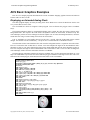
ACS Basic Graphics Examples .................................................................................................. 73
Displaying an Animated Analog Clock ..................................................................................................73
Index .............................................................................................................................................. 74
ACS Basic Graphics Programming Manual
26 February 2015
ACS Basic Graphics Programming
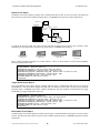
ACS Basic provides several commands to draw graphics. When used with the Color LCD 320x240 Terminal the
graphics are displayed on an actual LCD display screen. When used with the CFSound-IV the graphics are displayed
on a virtual screen that may be viewed and interacted with via a VNC network connection. In this manual the word
‘display’ refers to the Color LCD 320x240 Terminal LCD display screen or the CFSound-IV virtual display screen.
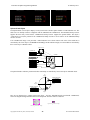
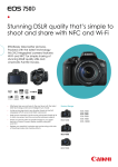
Screen Coordinates
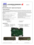
The graphic drawing commands use pairs of numbers to identify where you want to draw on the display. In
computer terminology these are referred to as screen coordinates. The first number of the pair is the X coordinate
and identifies a horizontal starting point that ranges from zero to one less than the width of the display (0 – 319).
The second number of the pair is the Y coordinate and identifies a vertical starting point that ranges from zero to one
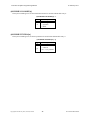
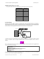
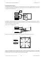
less than the height of the display (0 – 239). The X and Y coordinates for drawing start at 0, 0 at the lower left
corner of the display and range to 319, 239 at the upper right corner of the display as shown in this diagram:
X=0, y=239
X=319, y=239
Screen Coordinates
X=0, y=0
X=319, y=0
Drawing is clipped at the coordinate boundaries of the display – commands that specify coordinates outside of
these boundaries will not affect the display when either coordinate exceeds these values.
Pixels
The screen is divided up into thousands of dots arranged in columns (0 – 319) and rows (0 – 239) that can be
individually colored with one of 65536 colors. In computer terminology these dots are referred to as pixels. The
pixel color is selected by specifying the amount of three pure color components that are added to form the desired
color – the amount of Red, the amount of Green and the amount of Blue. In computer terminology this is referred to
as an additive RGB color model.
The display supports 32 Red levels (0 – 31), 64 Green levels (0 – 63) and 32 Blue levels (0 – 31) for each pixel.
There are more green levels than red or blue because the human eye is most sensitive to changes in green. Thirty
two unique values can be determined using 5 binary bits, and sixty three unique values can be specified using 6
binary bits – so this form of RGB color encoding is known as RGB565. Hey – the total number of bits is 16 – the
same number in our integer arithmetic! So, since the colors are additive, black must be equal to zero, and white must
be equal to 65535 (largest 16-bit number).
The ACS Basic drawing commands allow your program to control the colors of one or more pixels at a time,
depending upon the command, to draw graphic objects. The command to draw a single pixel is the simplest
command – this table shows how the command is constructed and what the command arguments are (don’t type this
in directly, it is a description showing you how to construct this command):
DRAW.PIXEL x,y,color
x screen x coordinate (0 – 319)
y screen y coordinate (0 – 240)
color RGB565 pixel color
Sets the pixel at x,y on the
current drawing @SURFACE to color
Copyright©1992-2015 by ACS, Sarasota, Florida
1
ALL RIGHTS RESERVED
ACS Basic Graphics Programming Manual
26 February 2015
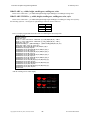
Let us use this description to construct a command that draws a white pixel at the center of the screen – don’t
worry about the @SURFACE system variable for now – we need to specify the x and y coordinates and the desired
pixel color:
draw.pixel 160,120,65535
The white pixel is probably hard to see amongst the text on the screen – you could draw a red pixel that might be
easier to see but how to you specify the red color? There is a built-in function for that.
The RGB(r, g, b) function takes three arguments, red level r (0 – 255), green level g (0 – 255) and blue level b (0
– 255) and does the math to combine them into a 16-bit integer – which is its return value. So let us use this to draw
a red pixel:
draw.pixel 160,120,rgb(255,0,0)
Kind of hard to see – the individual pixels are kind of small and there is a lot of clutter on the screen. Let us use
another system variable to stop showing the program text and PRINT output on the small screen – they will still
show on your connected communications device. The ANSI operating mode can be turned off by setting the
@ANSI.ENABLE system variable to zero:
@ANSI.ENABLE=0
Now as you type, or PRINT, the output doesn’t affect the screen. As a default, so nobody wonders where their
PRINT output, error message or Ready prompt went, the @ANSI.ENABLE is set to one whenever a program is run
or stops running. So if you don’t want ANSI output on the screen while your program is running you will have to
turn it off at the beginning of your program, and keep your program running.
Clearing The Screen
One last thing – how do we clear the screen so we can see the pixel? Turns out that there is a command for that
to – in computer terminology this is referred to a filling the screen. Here is the command format:
DRAW.FILL x, y, width, height, color
x screen x coordinate (0 –
Sets the width by height pixels
y screen y coordinate (0 –
starting at x, y on the current
width number of pixels wide to
drawing @SURFACE to color
height number of pixels high to
color RGB565 fill pixels color
319)
240)
fill
fill
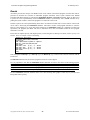
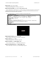
So try it:
draw.fill 0, 0, 320, 240, RGB(0, 0, 0)
You can experiment with different positions, widths, heights and colors. So now we have enough for a simple
graphics program:
10
15
20
25
30
REM Draw a red pixel at the center of the screen
@ANSI.ENABLE=0
DRAW.FILL 0,0,320,240,RGB(0,0,0)
DRAW.PIXEL 160,120,RGB(255,0,0)
GOTO 30
Copyright©1992-2015 by ACS, Sarasota, Florida
2
ALL RIGHTS RESERVED
ACS Basic Graphics Programming Manual
26 February 2015
Drawing Lines
How about drawing lines? Let us try drawing a green line diagonally from one corner of the screen to the other.
Here is the command format:
DRAW.LINE sx, sy, ex, ey, color
sx starting x coordinate (0
Draws a line from sx, sy to ex,
sy starting y coordinate (0
ey on the current drawing
ex ending x coordinate (0 –
@SURFACE using color
ey ending y coordinate (0 –
color RGB565 line pixels color
– 319)
– 240)
319)
240)
Here is the program:
10
15
20
25
30
REM Draw a green line from lower-left to upper-right
@ANSI.ENABLE=0
DRAW.FILL 0,0,320,240,RGB(0,0,0)
DRAW.LINE 0,0,319,239,RGB(0,255,0)
GOTO 30
Copyright©1992-2015 by ACS, Sarasota, Florida
3
ALL RIGHTS RESERVED
ACS Basic Graphics Programming Manual
26 February 2015
Drawing Arcs
How about drawing arcs? You could compute and draw each pixel making up the arc, or have ACS Basic draw it
for you if you provide the center, width, height and starting/ending angles. Here is the command format:
DRAW.ARC x,y,width,height,start,end,color
x center x coordinate (0 – 319)
Draws an arc centered at x,y of
y center y coordinate (0 – 240)
width,height beginning at start
width arc width (0 – 319)
angle and ending on end angle on
height arc height (0 – 240)
the current drawing @SURFACE using
start starting angle (0 - 359)
color
end ending angle (0 – 359)
color RGB565 box pixels color
Here is the program:
10
15
20
25
30
REM draw a red 90 degree arc at the screen center
@ANSI.ENABLE=0
DRAW.FILL 0,0,320,240,RGB(0,0,0)
DRAW.ARC 160,120,100,100,45,135,RGB(255,0,0)
GOTO 30
Copyright©1992-2015 by ACS, Sarasota, Florida
4
ALL RIGHTS RESERVED
ACS Basic Graphics Programming Manual
26 February 2015
Drawing Arcs with Style
There is another arc drawing command that allows the arc to be ‘styled’. Here is the command format:
DRAW.ARC.STYLED x,y,width,height,start,end,color,style
x center x coordinate (0 – 319)
y center y coordinate (0 – 240)
width arc width (0 – 319)
Draws a ‘styled’ arc centered
height arc height (0 – 240)
at x,y of width,height
start starting angle (0 - 359)
beginning at start angle and
end ending angle (0 – 359)
ending on end angle on the
color RGB565 box pixels color
current drawing @SURFACE
style combination of zero or more style bits
using color
that are ‘or’ed together (0 – 7):
1 – Chord
2 – No Fill
4 - Edged
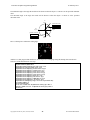
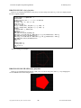
Here is a program to show the effect of the various combinations of the style bits:
10 REM arc demo
20 @ANSI.ENABLE=0
30 REM draw grid
40 FOR x = 64 TO 256 STEP 64 : DRAW.LINE x,0,x,239,RGB(64,64,64) : NEXT x
50 FOR y = 80 TO 160 STEP 80 : DRAW.LINE 0,y,319,y,RGB(64,64,64) : NEXT y
60 REM init text font
70 @FONT.HALIGN[0]=1 : @FONT.VALIGN[0]=2 : @FONT.FCOLOR[0]=RGB(255,255,255)
80 REM draw eight styles of filled arcs
90 DRAW.ARC.FILLED 64,80,80,80,45,135,RGB(255,0,0),0
100 DRAW.TEXT 0,64,80,"Style=0"
110 DRAW.ARC.FILLED 128,80,80,80,45,135,RGB(255,0,0),1
120 DRAW.TEXT 0,128,80,"Style=1"
130 DRAW.ARC.FILLED 192,80,80,80,45,135,RGB(255,0,0),2
140 DRAW.TEXT 0,192,80,"Style=2"
150 DRAW.ARC.FILLED 256,80,80,80,45,135,RGB(255,0,0),3
160 DRAW.TEXT 0,256,80,"Style=3"
170 DRAW.ARC.FILLED 64,160,80,80,45,135,RGB(255,0,0),4
180 DRAW.TEXT 0,64,160,"Style=4"
190 DRAW.ARC.FILLED 128,160,80,80,45,135,RGB(255,0,0),5
200 DRAW.TEXT 0,128,160,"Style=5"
210 DRAW.ARC.FILLED 192,160,80,80,45,135,RGB(255,0,0),6
220 DRAW.TEXT 0,192,160,"Style=6"
230 DRAW.ARC.FILLED 256,160,80,80,45,135,RGB(255,0,0),7
240 DRAW.TEXT 0,256,160,"Style=7"
999 GOTO 999
Copyright©1992-2015 by ACS, Sarasota, Florida
5
ALL RIGHTS RESERVED
ACS Basic Graphics Programming Manual
26 February 2015
Drawing Boxes
How about drawing boxes? You could compute and draw each line making up the box, or have ACS Basic draw
it for you if you provide the locations of two diagonal corners. Here is the command format:
DRAW.BOX x1,y1,x2,y2,color
x1 corner 1 x
Draws a box from diagonal
y1 corner 1 y
corners x1,y1 to x2,y2 on the
x2 corner 2 x
current drawing @SURFACE using
y2 corner 2 y
color
color RGB565 box
coordinate (0
coordinate (0
coordinate (0
coordinate (0
pixels color
–
–
–
–
319)
240)
319)
240)
Here is the program:
10
15
20
25
30
REM Draw a blue box around the screen edge
@ANSI.ENABLE=0
DRAW.FILL 0,0,320,240,RGB(0,0,0)
DRAW.BOX 0,0,319,239,RGB(0,0,255)
GOTO 30
and if you want a filled box:
10
15
20
25
30
REM Draw a blue box around the screen edge
@ANSI.ENABLE=0
DRAW.FILL 0,0,320,240,RGB(0,0,0)
DRAW.BOX.FILLED 60,60,260,180,RGB(0,0,255)
GOTO 30
Copyright©1992-2015 by ACS, Sarasota, Florida
6
ALL RIGHTS RESERVED
ACS Basic Graphics Programming Manual
26 February 2015
Drawing Circles
How about drawing a circle? Here is the command format:
DRAW.CIRCLE x,y,r,color
x center
Draws a circle of radius r
y center
centered at x, y on the current
r circle
drawing @SURFACE using color
color RGB565
x coordinate (0 – 319)
y coordinate (0 – 240)
radius(0 – 319)
circle pixels color
and here is a program to draw a yellow circle centered on the screen:
10
15
20
25
30
REM Draw a blue box around the screen edge
@ANSI.ENABLE=0
DRAW.FILL 0,0,320,240,RGB(0,0,0)
DRAW.CIRCLE 160,120,100,RGB(255,255,0)
GOTO 30
Drawing Ellipses
How about drawing an Ellipse? Here is the command format:
DRAW.ELLIPSE x, y, width, height, color
x center x coordinate (0 – 319)
Draws a width by height
y center y coordinate (0 – 240)
ellipse centered at x, y on
width major axis width
the current drawing @SURFACE
height minor axis width
to color
color RGB565 ellipse pixels color
and here is a program to draw a magenta ellipse centered on the screen:
10
15
20
25
30
REM Draw a blue box around the screen edge
@ANSI.ENABLE=0
DRAW.FILL 0,0,320,240,RGB(0,0,0)
DRAW.ELLIPSE 160,120,100,50,RGB(255,0,255)
GOTO 30
If you want a filled ellipse change line 25:
25 DRAW.ELLIPSE.FILLED 160,120,100,50,RGB(255,0,255)
Copyright©1992-2015 by ACS, Sarasota, Florida
7
ALL RIGHTS RESERVED
ACS Basic Graphics Programming Manual
26 February 2015
Drawing Polygons
A polygon is a flat shape consisting of straight lines that are joined to form a closed chain. A triangle is just a 3sided polygon, a box is a 4-sided polygon with right angles between the sides. An N-sided polygon requires N
coordinate pairs for its vertices.
How can we format a polygon draw command that can take a variable number of coordinates? The answer is to
use an array of numbers to store each coordinate and just provide the array names to the polygon command.
Array variables are just a table of numbers or strings. In order to use an array you have to tell Basic how big of a
table that you want. Basic then sets aside the correct amount of memory for that variable to hold the number of
values that you require. In computer terminology this is referred to as dimensioning an array. Basic provides a
DIMension command for this purpose:
30 DIM x[3],y[3]
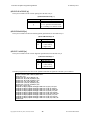
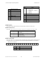
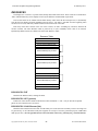
When you access the individual values in this array you specify an index into the table to select which value that
you want. The index follows the variable name and is enclosed in brackets [ ]. Here is a conceptual picture of what a
5 element numeric array looks like. Notice that there are 5 elements, numbered 0 – 4:
DIM Variable[5]
0
1
Variable[2] → 2
3
4
values
Since each array variable holds a single set of values, to draw a polygon you will need two arrays: one for the X
coordinates of each vertex and one for the Y coordinates. Your program ‘fills’ these arrays with the coordinates for
each point – prior to calling the DRAW.POLYGON command. The command looks at the dimensioned size of these
coordinate arrays to determine how many sides (and vertices) that the polygon should be drawn with.
So let us draw a 3-sided polygon – a triangle – centered on the screen. We need X and Y coordinate arrays that
each hold 3 values. Here is the program:
10
20
30
40
50
60
70
80
REM Draw a triangle
@ANSI.ENABLE=0
DIM x[3],y[3] : REM Allocate coordinate arrays
DRAW.FILL 0,0,320,240,RGB(0,0,0)
REM Load x & y coordinates
x[0]=100:y[0]=60:x[1]=220:y[1]=60:x[2]=160:y[2]=180
DRAW.POLYGON x,y,RGB(255,128,128)
GOTO 80
And you can also fill it in – change the DRAW.POLYGON command to DRAW.POLYGON.FILLED.
Copyright©1992-2015 by ACS, Sarasota, Florida
8
ALL RIGHTS RESERVED
ACS Basic Graphics Programming Manual
26 February 2015
Drawing Text
Let us say that we need to put text on the screen along with our graphics. You could leave the @ANSI.ENABLE
system variable set to one, and use PRINT commands. How do you control where the text appears on the screen?
The @ANSI command has a few additional modifiers – two of which allow you to read the current ANSI row
and column values, or set them before printing: @ANSI.ROW and @ANSI.COL. The ANSI rows and columns are
numbered like this starting in the upper left of the screen:
Col 0
Col 1
…
Col 2
Row 0
Row 1
Row 2
…
…
…
Row 17
Row 18
Row 19
…
Col 42
Col43
Col 44
Try it out – PRINT Hello in the middle of the screen:
@ANSI.ROW = 10 : @ANSI.COL = 17 : PRINT “Hello!”
While this does work – there are a few problems. The cursor appears, blinking, on the screen – which you may
not want. You can turn this off with another @ANSI command:
@ANSI.CURSOR = 0 : REM Turn off ANSI cursor
And, if you PRINT on the bottom line of the screen without a trailing semi-colon – or if the text wraps to the
next line the screen will scroll up. You can turn these features off with another couple @ANSI commands:
@ANSI.WRAP = 0 : REM Turn off ANSI line wrap
@ANSI.SCROLL = 0 : REM Turn off ANSI screen scrolling
While this method of drawing text can be made to work, the positioning is coarse, the characters are always
white on black, and you are stuck with the character height and style that ANSI operation uses. We’ll examine an
alternative text display method next which uses another DRAW command along with some additional system
commands to control the text appearance.
Copyright©1992-2015 by ACS, Sarasota, Florida
9
ALL RIGHTS RESERVED
ACS Basic Graphics Programming Manual
26 February 2015
Drawing Text with Style
The shape, appearance and size of drawn text characters specify the text’s style. In computer terminology the
style of text is referred to as a font. ACS Basic provides support for up to 32 different fonts to be in use at a time.
Each of the 32 fonts can be configured by your program to change the text color, relative position and appearance.
The entries in this font table are accessed through system variables. The individual character shapes and their size
are obtained from another table in memory by their name – these are the actual embedded fonts. The two pieces of
information: the embedded font to use and how it is colored and positioned are selected as an entry in the font table
used to draw the desired text. In computer terminology this is referred to as rendering text.
The embedded fonts must be loaded into the device’s memory in order to be used for drawing text. They are
stored in a collection with other items where they can be quickly accessed by their name.
It is a Matter of Resources
In the ACS products that support Basic Graphics commands there are a collection of fonts and other objects that
the Basic can draw with – they are collectively known as Resources. The Color LCD 320x240 Terminal first looks
for resources to load in an on-board flash memory. Both the Color LCD and CFSound-IV look for resources to load
on the SD card installed by trying to load a binary file named Resources.bin .
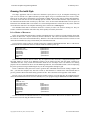
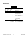
You can list the resources that are currently loaded, the command is RESOURCES.LIST. Here is what the list
would look like if no additional resources could be found and loaded at power-up:
resources.list
AcsAnsiFont.efnt
AcsDefaultFont.efnt
ButtonK.bmp
ButtonK2.bmp
ButtonK4.bmp
ButtonM.bmp
Ready
12,604
27,940
1,610
2,050
3,018
2,618
builtin
builtin
builtin
builtin
builtin
builtin
There are a few resources that are built-in: they are required to allow the status, Configuration Settings screen
and other features to operate if no additional resources can be found. The files with the .EFNT extension are
‘embedded font files’. They contain the information about the size and shape of the text characters for drawing
purposes. The AcsAnsiFont.efnt file is used for PRINTing ANSI text, the AcsDefaultFont.efnt is used for displaying
the power-up status messages and labeling the keys on the Configuration Settings keypad.
There is a Windows utility that can be used to generate these embedded font files from existing computer font
files – you select the computer font, what size to make it, what characters to include in the font and what name to
give the generated .EFNT file and the utility generates the file. This is described in an Appendix of this manual.
How do you get your embedded font files into the product resources? You can then place the embedded font file
on the SD card and load it into the resources manually or in your program using the RESOURCES.ADD command:
resources.add ComicSansBold14.efnt
Ready
resources.list
ComicSansBold14.efnt
AcsAnsiFont.efnt
AcsDefaultFont.efnt
ButtonK.bmp
ButtonK2.bmp
ButtonK4.bmp
ButtonM.bmp
Ready
25,666
12,604
27,940
1,610
2,050
3,018
2,618
builtin
builtin
builtin
builtin
builtin
builtin
So there are at least two embedded font files to work with that are built-in. How can we use these to draw text on
the screen? Let us look using the FONTS commands.
Copyright©1992-2015 by ACS, Sarasota, Florida
10
ALL RIGHTS RESERVED
ACS Basic Graphics Programming Manual
26 February 2015
There is a Table of Fonts
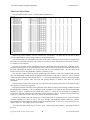
Just like with the resources, there is a FONTS.LIST command. Try it:
fonts.list
F#, "Resource Name
0, "AcsDefaultFont.efnt
1, "AcsAnsiFont.efnt
2, "AcsAnsiFont.efnt
3, "AcsDefaultFont.efnt
4, "AcsDefaultFont.efnt
5, "AcsDefaultFont.efnt
6, "AcsDefaultFont.efnt
7, "AcsDefaultFont.efnt
8, "AcsDefaultFont.efnt
9, "AcsDefaultFont.efnt
10, "AcsDefaultFont.efnt
11, "AcsDefaultFont.efnt
12, "AcsDefaultFont.efnt
13, "AcsDefaultFont.efnt
14, "AcsDefaultFont.efnt
15, "AcsDefaultFont.efnt
16, "AcsDefaultFont.efnt
17, "AcsDefaultFont.efnt
18, "AcsDefaultFont.efnt
19, "AcsDefaultFont.efnt
20, "AcsDefaultFont.efnt
21, "AcsDefaultFont.efnt
22, "AcsDefaultFont.efnt
23, "AcsDefaultFont.efnt
24, "AcsDefaultFont.efnt
25, "AcsDefaultFont.efnt
26, "AcsDefaultFont.efnt
27, "AcsDefaultFont.efnt
28, "AcsDefaultFont.efnt
29, "AcsDefaultFont.efnt
30, "AcsDefaultFont.efnt
31, "AcsDefaultFont.efnt
Ready
",
",
",
",
",
",
",
",
",
",
",
",
",
",
",
",
",
",
",
",
",
",
",
",
",
",
",
",
",
",
",
",
",
BCOLOR
,
RGB( 0, 0, 0),
RGB( 0, 0, 0),
RGB(255,255,255),
RGB( 0, 0, 0),
RGB( 0, 0, 0),
RGB( 0, 0, 0),
RGB( 0, 0, 0),
RGB( 0, 0, 0),
RGB( 0, 0, 0),
RGB( 0, 0, 0),
RGB( 0, 0, 0),
RGB( 0, 0, 0),
RGB( 0, 0, 0),
RGB( 0, 0, 0),
RGB( 0, 0, 0),
RGB( 0, 0, 0),
RGB( 0, 0, 0),
RGB( 0, 0, 0),
RGB( 0, 0, 0),
RGB( 0, 0, 0),
RGB( 0, 0, 0),
RGB( 0, 0, 0),
RGB( 0, 0, 0),
RGB( 0, 0, 0),
RGB( 0, 0, 0),
RGB( 0, 0, 0),
RGB( 0, 0, 0),
RGB( 0, 0, 0),
RGB( 0, 0, 0),
RGB( 0, 0, 0),
RGB( 0, 0, 0),
RGB( 0, 0, 0),
FCOLOR
, SPACINGX, SPACINGY, HALIGN, VALIGN, BTRANS, FTRANS
RGB(255,255,255),
0,
0,
1,
1,
1,
0
RGB(255,255,255),
0,
0,
0,
1,
1,
0
RGB( 0, 0, 0),
0,
0,
0,
1,
0,
0
RGB( 0, 0, 0),
0,
0,
1,
0,
1,
0
RGB(255,255,255),
0,
0,
0,
0,
1,
0
RGB(255,255,255),
0,
0,
1,
1,
1,
0
RGB(255,255,255),
0,
0,
1,
1,
1,
0
RGB( 0, 0, 0),
0,
0,
1,
1,
1,
0
RGB(255,255,255),
0,
0,
1,
1,
1,
0
RGB( 0, 0, 0),
0,
0,
1,
1,
1,
0
RGB(255,255,255),
0,
0,
1,
1,
1,
0
RGB( 0, 0, 0),
0,
0,
1,
1,
1,
0
RGB(255,255,255),
0,
0,
1,
1,
1,
0
RGB( 0, 0, 0),
0,
0,
1,
1,
1,
0
RGB(255,255,255),
0,
0,
1,
1,
1,
0
RGB( 0, 0, 0),
0,
0,
1,
1,
1,
0
RGB(255,255,255),
0,
0,
1,
1,
1,
0
RGB( 0, 0, 0),
0,
0,
1,
1,
1,
0
RGB(255,255,255),
0,
0,
1,
1,
1,
0
RGB( 0, 0, 0),
0,
0,
1,
1,
1,
0
RGB(255,255,255),
0,
0,
1,
1,
1,
0
RGB( 0, 0, 0),
0,
0,
1,
1,
1,
0
RGB(255,255,255),
0,
0,
1,
1,
1,
0
RGB( 0, 0, 0),
0,
0,
1,
1,
1,
0
RGB(255,255,255),
0,
0,
1,
1,
1,
0
RGB( 0, 0, 0),
0,
0,
1,
1,
1,
0
RGB(255,255,255),
0,
0,
1,
1,
1,
0
RGB( 0, 0, 0),
0,
0,
1,
1,
1,
0
RGB(255,255,255),
0,
0,
1,
1,
1,
0
RGB( 0, 0, 0),
0,
0,
1,
1,
1,
0
RGB(255,255,255),
0,
0,
1,
1,
1,
0
RGB( 0, 0, 0),
0,
0,
1,
1,
1,
0
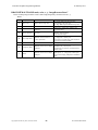
What are all of these numbers? The first column is the ‘font number’ – the index into the font table. In Basic
you can treat this table as an array using an index to access individual rows.
The second column is the embedded font file name in the resources that will be used to render text using this font
table entry. Note that when setting the .efnt resource to be used by an entry, that entry has to exist in the resources –
if it doesn’t an error will occur.
The next two columns indicate what Background color (BCOLOR) and Foreground color (FCOLOR) will be
used when rendering the text. The FCOLOR is the color of the actual character pixels, the BCOLOR is the color of
the pixels surrounding the character. The values in the table are 16-bit RGB565 values – they are shown in the
listing as if they were set using the RGB( ) function – which they can be.
The next four columns control the relative positioning of the characters when text is rendered with this font
entry. The SPACINGX column controls the spacing between characters of the font. A value of ‘0’ will use the fixed
width of the font to place the following character. A ‘-1’ will use the “bounding box” character width for horizontal
spacing. A non-zero, positive value will force that spacing character to character when fonts are oriented
horizontally.
The SPACINGY column works in the same way but affects vertical spacing when fonts are oriented vertically.
(this operation is not currently supported)
The ALIGN columns control the relative placement of the drawn text relative to the starting coordinate provided
the DRAW.TEXT command – or the text alignment to the coordinates. The HALIGN entry controls the horizontal
alignment: a value of ‘0’ justifies the text from the left, a value of ‘1’ centers the text and a value of ‘2’ justifies the
text from the right. The VALIGN entry controls the vertical alignment: a value of ‘0’ justifies the text from the top,
a value of ‘1’ centers the text and a value of ‘2’ justifies the text from the bottom.
The last two columns control the transparency of the rendered text. A transparent pixel is not drawn with the
result that anything it is drawn on top of will ‘show through’. The BTRANS column controls the character
background pixels and the FTRANS column controls the foreground pixels. A value of ‘0’ forces those pixels to be
drawn, a value of ‘1’ forces those pixels to not be drawn.
All of these font table entries may be accessed – read / written using system variables – specifying an index of
the entry:
Copyright©1992-2015 by ACS, Sarasota, Florida
11
ALL RIGHTS RESERVED
ACS Basic Graphics Programming Manual
System Variable
Values
@FONT.EFNT$[entry]
“resource.efnt”
@FONT.BCOLOR[entry]
RB565 pixel color
@FONT.FCOLOR[entry]
RB565 pixel color
@FONT.SPACINGX[entry]
@FONT.SPACINGY[entry]
@FONT.HALIGN[entry]
@FONT.VALIGN[entry]
@FONT.BTRANS[entry]
@FONT.FTRANS[entry]
26 February 2015
-1
0
>0
-1
0
>0
0
1
2
0
1
2
0
1
0
1
Description
Gets/Sets embedded font resource for entry – the
resource must exist in the resource table to set
Gets/Sets font background color for entry – use
RGB( ) to set
Gets/Sets font foreground color for entry – use
RGB( ) to set
= bounding box
= fixed width
= spacing
= bounding box
= fixed width
= spacing
= left justify
= center justify
= right justify
= top justify
= center justify
= bottom justify
= normal
= transparent
= normal
= transparent
Copyright©1992-2015 by ACS, Sarasota, Florida
Gets/Sets font horizontal spacing
Gets/Sets font vertical spacing
(not currently supported)
Gets/Sets font horizontal alignment
Gets/Sets font vertical alignment
Gets/Sets font background transparency
Gets/Sets font foreground transparency
12
ALL RIGHTS RESERVED
ACS Basic Graphics Programming Manual
26 February 2015
And Now Back to Drawing the Text
So now we can get back to the DRAW.TEXT command. As with the other commands here is the command
format:
DRAW.TEXT f, x, y, expr
Renders the expression on
f font table entry number (0 – 31)
the current drawing @SURFACE
x justification x coordinate (0 – 319)
relative to x, y using the
y justification y coordinate (0 – 240)
font table entry f values
expr the number or string to draw
So let us try this out. There is already some default entries in the font table. What if we write a simple program
that draws “Hello!” in the center of the screen using Font zero:
10
20
30
40
REM Draw text
@ANSI.ENABLE=0
DRAW.TEXT 0,160,120,"Hello!"
GOTO 40
Let us make the font red; set Font zero’s foreground color to red before drawing the text:
10
20
25
30
40
REM Draw red text
@ANSI.ENABLE=0
@FONT.FCOLOR[0]=RGB(255,0,0)
DRAW.TEXT 0,160,120,"Hello!"
GOTO 40
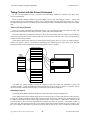
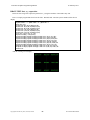
What do all of these alignment options do – there are nine combinations. Here is a program to show you how the
@FONT.HALIGN and @FONT.VALIGN system variables control the relative text positioning. First we draw a
grid using DRAW.LINE commands, then we DRAW.TEXT at the grid intersection points with the various font
alignment options to show how they affect the text rendering:
5 REM Test font HALIGN and VALIGN
10 @ANSI.ENABLE=0
20 REM Draw grid
30 DRAW.LINE 10,0,10,239,RGB(255,0,0)
40 DRAW.LINE 160,0,160,239,RGB(255,0,0)
50 DRAW.LINE 309,0,309,239,RGB(255,0,0)
60 DRAW.LINE 0,10,319,10,RGB(255,0,0)
70 DRAW.LINE 0,120,319,120,RGB(255,0,0)
80 DRAW.LINE 0,229,319,229,RGB(255,0,0)
90 REM Draw aligned text
100 @FONT.HALIGN[0]=0:@FONT.VALIGN[0]=0:DRAW.TEXT
110 @FONT.HALIGN[0]=1:@FONT.VALIGN[0]=0:DRAW.TEXT
120 @FONT.HALIGN[0]=2:@FONT.VALIGN[0]=0:DRAW.TEXT
130 @FONT.HALIGN[0]=0:@FONT.VALIGN[0]=1:DRAW.TEXT
140 @FONT.HALIGN[0]=1:@FONT.VALIGN[0]=1:DRAW.TEXT
150 @FONT.HALIGN[0]=2:@FONT.VALIGN[0]=1:DRAW.TEXT
160 @FONT.HALIGN[0]=0:@FONT.VALIGN[0]=2:DRAW.TEXT
170 @FONT.HALIGN[0]=1:@FONT.VALIGN[0]=2:DRAW.TEXT
180 @FONT.HALIGN[0]=2:@FONT.VALIGN[0]=2:DRAW.TEXT
190 GOTO 190
Copyright©1992-2015 by ACS, Sarasota, Florida
13
0,10,10,"LEFT,BOT"
0,160,10,"MID,BOT"
0,309,10,"RIGHT,BOT"
0,10,120,"LEFT,MID"
0,160,120,"MID,MID"
0,309,120,"RIGHT,MID"
0,10,229,"LEFT,TOP"
0,160,229,"MID,TOP"
0,309,229,"RIGHT,TOP"
ALL RIGHTS RESERVED
ACS Basic Graphics Programming Manual
26 February 2015
Drawing Images
Using all of the DRAWing command you can construct pretty line art displays. But how do we draw images –
like photos or Photoshop generated graphics?
There is a DRAW.BITMAP command that will allow you to do this. While it is simple to use there are a few
caveats:
1.
The image to be drawn on the screen must be a Windows .BMP bitmap file.
2.
The image must be resident in the device’s memory by being a Resource in the Resource table.
To quickly try this command we’ll use one of the built-in image resources. Use a RESOURCES.LIST command
with a wildcard name pattern to list all of the image resources:
resources.list *.bmp
ButtonK.bmp 1,610 builtin
ButtonK2.bmp 2,050 builtin
ButtonK4.bmp 3,018 builtin
ButtonM.bmp 2,618 builtin
Ready
The names suggest that these are images of the buttons that the device uses for the Configuration Settings screen
keyboard. They have to be ‘built-in’ so that they are always there – even when no other resources are loaded.
So let us draw one of the button images in the center of the screen. As before here is the command format from
the Reference:
Renders the bitmap
resource on the
current drawing
@SURFACE at x, y
DRAW.BITMAP x, y, imageResourceName
x image lower-left x coordinate (0 – 319)
y image lower-left y coordinate (0 – 240)
the string name of the loaded image
imageResourceName
resource to draw
Type the following commands – first let us clear the screen:
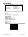
draw.fill 0,0,320,240,RGB(0,0,0)
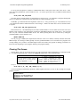
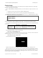
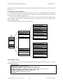
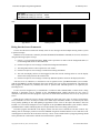
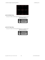
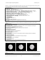
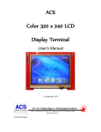
This leaves the Ready prompt and blinking cursor at the top of the screen – OK for now. Now let us draw the
ButtonK4.bmp image at the center of the screen. Type the following command:
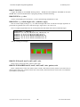
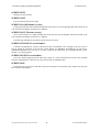
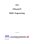
draw.bitmap 160,120,"ButtonK4.bmp"
Your screen should now look like:
Surprise! The image looks like the Configuration Settings screen keypad spacebar – without any colors.
Why isn’t it shown in the center of the screen at 160, 120? This is because the DRAW.BITMAP coordinates
reference where the lower-left corner of the bitmap image will be drawn. The ButtonK4.bmp happens to be 88
pixels wide by 22 pixels tall. So we could center it by subtracting half of these values from the x and y coordinates.
Let us try moving it - type the following command:
Copyright©1992-2015 by ACS, Sarasota, Florida
14
ALL RIGHTS RESERVED
ACS Basic Graphics Programming Manual
26 February 2015
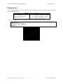
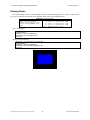
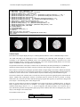
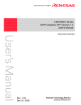
draw.bitmap 160-88/2,120-22/2,"ButtonK4.bmp"
Your screen should now look like:
Notice that it is centered now, and also that it was drawn on top of what was already there – like stacking photos.
The effect of all of the DRAW commands is cumulative – each one builds upon the resulting image.
There are additional variations on the DRAW.BITMAP command that support transparency and indexing. These
are outlined in the ACS Basic Reference section of this manual.
Rules for Drawing
1.
DRAWing commands use x (horizontal) and y (vertical) coordinates to control where they affect the
screen.
2.
Graphic DRAWing commands specify the color to use with a 16-bit additive RGB color model – expressed
with a signed integer value or using the RGB(red,green,blue) function.
3.
The DRAW.POLYGON commands require arrays of the x and y coordinates of the polygon vertices. The
arrays must be pre-DIMensioned and loaded with the vertex coordinates before the polygon can be drawn.
4.
The DRAW.TEXT command uses embedded font file (.EFNT) resources to render the text on the screen.
The style, color, alignment and transparency of the drawn text are controlled by referring to a configured
entry in the FONTS table.
5.
The DRAW.BITMAP commands render Windows .BMP image resources on the screen. The x and y
coordinates refer to the placement of the lower-left corner of the image resource on the screen.
6.
Drawing is cumulative – each successive DRAW command builds on the results of prior commands.
Making Things Move
So we know how to make static screens using the DRAW commands. How do we make something that moves?
Let us draw a simple old-style sonar screen – like the ones used on submarines. It consisted of a circle and a
sweeping line that rotated from the center. We know how to clear the screen, draw the circle and line, but how do we
make the line rotate around the circle? We know the circle’s center coordinate would be the line’s starting point, but
how to we dynamically compute the rotating line’s end coordinate? For that we need to use some mathematics.
Warning – Mathematics
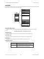
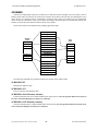
In mathematics, the trigonometric functions (also called circular functions) are functions of an angle. They are
used to relate the angles of a triangle to the lengths of the sides of a triangle.
The most familiar trigonometric functions are the sine and cosine. In the context of the standard unit circle with
radius 1, where a triangle is formed by a ray originating at the origin and making some angle with the x-axis, the
sine of the angle gives the length of the y-component (rise) of the triangle and the cosine gives the length of the xcomponent (run). Trigonometric functions are commonly defined as ratios of two sides of a right triangle containing
the angle, and can equivalently be defined as the lengths of various line segments from a unit circle.
Copyright©1992-2015 by ACS, Sarasota, Florida
15
ALL RIGHTS RESERVED
ACS Basic Graphics Programming Manual
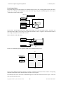
26 February 2015
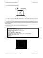
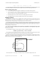
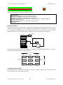
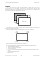
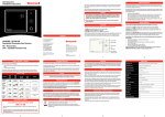
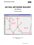
Here is a drawing showing this relationship:
Y
x=radius*Cos(angle)
y=radius*Sin(angle)
ra
di
us
y
ang
le
x
0,0
X
As we saw earlier in the ACS Basic User’s Manual section on functions, Basic has both SIN( ) and COS( )
functions. These trig functions take an angle argument and return the unit circle ratios – up scaled by 1024 since this
Basic only provides integer math.
In order to perform the radius multiplication and subsequent down scaling by 1024 the MULDIV( ) function is
used. This function multiplies the first two arguments as 32-bit integers and then divides by the third argument to
return a 16-bit result.
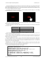
We now have the pieces we need to draw our sweeping sonar screen. To rotate the line we un-draw it at its old
angle then redraw it at the new angle as we sweep the angle through 360 degrees.
Here is the program:
10 REM Sonar Sweep
20 @ANSI.ENABLE=0:@BACKLIGHT=1
30 centerX = 160 : centerY = 120 : radius = 90
40 DRAW.FILL 0,0,320,240,RGB(0,0,0)
50 DRAW.CIRCLE centerX, centerY, radius, RGB(255,255,255)
60 FOR angle = 0 TO 359
70 lineX = MULDIV(radius-1, COS(angle), 1024)
80 lineY = MULDIV(radius-1, SIN(angle), 1024)
90 DRAW.LINE centerX, centerY, centerX + oldLineX, centerY + oldLineY, RGB(0,0,0)
100 DRAW.LINE centerX, centerY, centerX + lineX, centerY + lineY, RGB(255,255,255)
110 oldLineX = lineX : oldLineY = lineY
120 NEXT angle
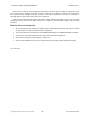
130 GOTO 60
Ready
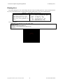
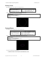
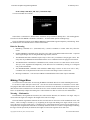
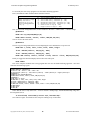
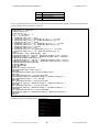
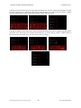
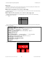
And here is what your display should look like – with the sweep line rotating counter-clockwise around the
circle origin:
Copyright©1992-2015 by ACS, Sarasota, Florida
16
ALL RIGHTS RESERVED
ACS Basic Graphics Programming Manual
26 February 2015
Moving Smarter
While this program works, there is a lot of flickering of the sweep line and we have to keep track of the line’s
old position so that we can un-draw it before redrawing it in its new position. There is a better way using an
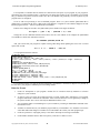
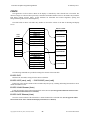
approach called ping-pong or double buffering.
With double buffering, drawing alternates between two different surfaces – one is shown while drawing on the
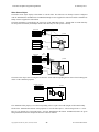
other, then they are switched and the process repeats.
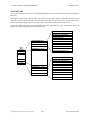
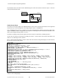
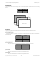
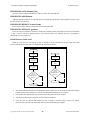
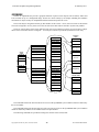
The ACS Basic Graphics actually has three drawing surfaces to support this approach: Display, Work and
Background:
The Background surface provides a content area
that can be seldom drawn, and copied to the Work
surface before additional drawing is done on top.
Background Surface = 2
g
To
Work Surface = 1
gl
e
Display Surface = 0
C
(shown on LCD)
The Work surface is where most drawing is done
before being swapped with the Display surface.
op
y
The Display surface is the one that is currently
being shown on the screen. This is the one that we
have been drawing on up to now.
All of the DRAW commands operate on the current drawing surface which is set using a system variable @SURFACE. The DRAW.TOGGLE command is used to swap the Work and Display surfaces – they aren’t copied,
the Work surface becomes the Display and the old Display becomes the Work surface.
In order to implement double buffering and avoid flickering as the display is updated we need to change our
program to use the following sequence:
Double-Buffering Sequence
1. Switch to the Background draw surface.
2. Draw any required static background content.
3. Switch to the Work surface.
4. Copy in the content from the Background surface to the Work surface and draw any dynamic content on
top of it.
5. Toggle the Work and Display surfaces.
6. Repeat from step 4.
Copyright©1992-2015 by ACS, Sarasota, Florida
17
ALL RIGHTS RESERVED
ACS Basic Graphics Programming Manual
26 February 2015
Let us modify the sonar sweep program to use this double buffering approach.
Here is the DRAW.COPY command format from the reference:
DRAW.COPY src,sx,sy,dx,dy,w,h
src source surface number (0, 1, 2)
Copies the width x height
sx source lower-left x coordinate (0 –
bitmap from the src
sy source lower-left y coordinate (0 –
surface @ sx,sy on the
dx destination lower-left x coordinate
current drawing @SURFACE
dy destination lower-left y coordinate
at dx, dy
w width of area to copy (1 – 320)
h height of area to copy (1 – 240)
319)
240)
(0 – 319)
(0 – 240)
First we’ll select the background surface, clear it and draw in the circle – which is static – it doesn’t change:
@SURFACE=2
DRAW.FILL 0,0,320,240,RGB(0,0,0)
DRAW.CIRCLE centerX, centerY, radius, RGB(255,255,255)
Next we’ll select the work surface:
@SURFACE=1
Then we copy the background surface area encompassing the circle and draw the sweep line on it:
DRAW.COPY 2, leftX, leftY, leftX, leftY, width, height
lineX = MULDIV(radius-1, COS(angle), 1024)
lineY = MULDIV(radius-1, SIN(angle), 1024)
DRAW.LINE centerX, centerY, centerX + lineX, centerY + lineY, RGB(255,255,255)
Finally we toggle the Work and Display surfaces then rinse and repeat.
DRAW.TOGGLE
Here is the complete modified sonar sweep program that now uses the double buffering approach – run it and
notice that the flickering is gone:
10 REM Sonar Sweep
20 @ANSI.ENABLE=0 : @BACKLIGHT=1
30 centerX = 160 : centerY = 120 : radius = 90
40 leftX=centerX-(radius+1) : leftY=centerY-(radius+1) : width=(radius+1)*2 : height=(radius+1)*2
50 @SURFACE=2
60 DRAW.FILL 0,0,320,240,RGB(0,0,0)
70 DRAW.CIRCLE centerX, centerY, radius, RGB(255,255,255)
80 @SURFACE=1
90 FOR angle = 0 TO 359
100 DRAW.COPY 2, leftX, leftY, leftX, leftY, width, height
110 lineX = MULDIV(radius-1, COS(angle), 1024)
120 lineY = MULDIV(radius-1, SIN(angle), 1024)
130 DRAW.LINE centerX, centerY, centerX + lineX, centerY + lineY, RGB(255,255,255)
140 DRAW.TOGGLE
150 NEXT angle
160 GOTO 90
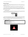
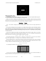
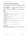
Notice that the circle is only drawn once – in fact it could be a bitmap image. Add the ButtonK4.bmp image into
the background screen:
75 draw.bitmap centerX-88/2,centerY-22/2,"ButtonK4.bmp"
Save and run it again. You should see the sweep line rotating on top of the button:
Copyright©1992-2015 by ACS, Sarasota, Florida
18
ALL RIGHTS RESERVED
ACS Basic Graphics Programming Manual
26 February 2015
Changing Direction
The last example ran the animation at full speed – there was no delay between screen updates and the angle was
incremented through an entire circle of 360 degrees in one degree steps.
What if you wanted to simulate the second hand of a clock? A few changes would be necessary; the motion
should only occur once per second, the rotation would have to move clockwise instead of counter-clockwise, and
since there are 60 seconds around the face of a clock the motion would have to advance:
360 𝑑𝑒𝑔𝑟𝑒𝑒𝑠
𝑑𝑒𝑔𝑟𝑒𝑒𝑠
=6
60 𝑠𝑒𝑐𝑜𝑛𝑑𝑠
𝑠𝑒𝑐𝑜𝑛𝑑
Also – zero seconds is straight up to the 12 o’clock position – which is not the zero angle position but 90
degrees.
Let us start by tackling the non-zero angle for zero seconds and the clockwise motion. Remember from the
earlier mathematics section that the angle advances counter-clockwise as the angle increases. If you change line 90
in the previous program to STEP the FOR/NEXT loop from 359 to 0 and run the program you will see that the
motion is now in the clockwise direction. If you change the STEP value from -1 to -6 the motion is faster, but still in
a clockwise direction.
So how can we translate the seconds to the required negative angle with the 90 degree offset? Let us start by
offsetting the zero angle from the 360 degree position by 90 degrees – 360 + 90 = 450 degrees. From the previous
equation and results we know that we have to subtract 6 degrees per second:
angle = (360 + 90) - (second * 6)
This equation yields angle = 450 when second = 0, and angle = 96 when second = 59. We need a way to limit the
range of the computed angle to 0 – 359 degrees for use with the SIN( ) and COS( ) functions.
Enter the modulus operator: %. Integer division truncates (discards) the fractional part of the result. The modulus
operator divides the value to its left by the value on its right and returns the remainder. When both values are equal
or integer multiples, the remainder of the division is zero. This can be evaluated as:
x % y = (x – ((x / y) * y))
Try computing the modulus of 4 for various values:
0%4
1%4
2%4
3%4
4%4
5%4
6%4
= (0 – ((0/4) * 4))
= (1 – ((1/4) * 4))
= (2 – ((2/4) * 4))
= (3 – ((3/4) * 4))
= (4 – ((4/4) * 4))
= (5 – ((5/4) * 4))
= (6 – ((6/4) * 4))
=0
=1
=2
=3
=0
=1
=2
You can see that the modulus ranges from zero when the arguments are equal to one less than the modulus. So
taking the modulus 360 of the angle computation returns an angle between 0 and 359:
Copyright©1992-2015 by ACS, Sarasota, Florida
19
ALL RIGHTS RESERVED
ACS Basic Graphics Programming Manual
26 February 2015
angle = ((360 + 90) - (second * 6) % 360)
If you now change lines 90 and 150 to count seconds from 0 to 59 and add line 95 to compute the angle you will
see the motion being driven counter-clockwise in 6 degree increments as the seconds range from 0 to 59.
Rules for Making Things Move
1.
To avoid flickering when moving graphics by DRAWing, use the double-buffering sequence.
2.
You can compute the X and Y coordinates for DRAWing circular motion using the trig functions SIN( )
and COS( ) and scale the results using the MULDIV( ) function.
3.
Incrementing angles rotate counter-clockwise, decrementing angles rotate clockwise.
4.
The modulus operator % returns the remainder of the division of the two arguments.
Staging an Event
We could add a 1 second delay using a @TIMER system variable and increment the second variable from zero
through fifty-nine every time that we read @TIMER is zero. There is another way that will allow our program to do
other things instead of simply spinning in a loop waiting on a timer. Welcome to Events.
Events are changes in your program’s execution that can happen in between each statement. The linear execution
of your program’s statements is interrupted to process the event and then execution resumes from where your
program was interrupted. Events are associated with and triggered by some system variables and can occur as a
result of hardware or software actions.
You control how system variable events are processed in your program by associating them with an event
handler. The event handler is a subroutine you write that will be called when the event is signaled by changes in the
associated system variable.
The event handler is configured or setup using the ACS Basic’s ONEVENT command:
ONEVENT @systemvariable, GOSUB linenumber
This command records the handler subroutine line number in an event table for the specified system variable
entry. Changes to system variables that cause events set a flag on their entry in the event table.
In between processing each program statement Basic scans the event table looking for flagged entries. When a
flagged entry is found Basic performs the GOSUB to the recorded event handler line number. When the event
handler subroutine returns, Basic clears the flagged entry.
10 ONEVENT @SECOND, GOSUB 10000
Setup @SECOND
event handler
20 IF A < 5 THEN A = A + 1
30 PRINT A
@SECOND
changes
40 FOR N = 0 TO A
50 B = B + A
60 NEXT N
...
10000 REM Event Handler
10010 S = @SECOND
10020 RETURN
Events are prioritized – an executing event handler can only be interrupted by a higher priority event.
Copyright©1992-2015 by ACS, Sarasota, Florida
20
ALL RIGHTS RESERVED
ACS Basic Graphics Programming Manual
26 February 2015
It is important to remember that all variables are shared between all parts of your program. If your program is
performing some long calculation using a variable and you change that variable in an event handler your program
may get confused or generate incorrect results since the event handler can potentially execute anywhere in your
program after it is configured.
So let us add event processing to our second hand program. There is a system variable @SECOND that is
updated once a second from the device’s Real Time Clock hardware. It signals an event when this happens. We will
turn the program lines 95 – 160 into a @SECOND event handler.
Edit line 95 to change the second to the @SECOND system variable in the angle calculation:
95 angle = ((360 + 90) - @SECOND * 6) % 360
Change line 150 to a RETURN statement and remove line 160. Now add line 85 to configure the @SECOND
event handler to call the new subroutine at line 95:
85 ONEVENT @SECOND,GOSUB 95
And, just to show that your program is capable of doing other things while updating the screen once a second
replace line 90 with:
90 a = a + 1 : PRINT a : GOTO 90
Your program should now look like:
10 REM Sonar Sweep
20 @ANSI.ENABLE=0:@BACKLIGHT=1
30 centerX = 160 : centerY = 120 : radius = 90
40 leftX = centerX-(radius+1) : leftY = centerY-(radius+1) : width = (radius+1)*2 : height = radius+1)*2
50 @SURFACE=2
60 DRAW.FILL 0,0,320,240,RGB(0,0,0)
70 DRAW.CIRCLE centerX, centerY, radius, RGB(255,255,255)
75 DRAW.BITMAP centerX-88/2,centerY-22/2,"ButtonK4.bmp"
80 @SURFACE=1
85 ONEVENT @SECOND,GOSUB 95
90 a = a + 1 : PRINT a : GOTO 90
95 angle = ((360 + 90) - @SECOND * 6) % 360
100 DRAW.COPY 2,leftX,leftY,leftX,leftY,width,height
110 lineX = MULDIV(radius-1, COS(angle), 1024)
120 lineY = MULDIV(radius-1, SIN(angle), 1024)
130 DRAW.LINE centerX, centerY, centerX + lineX, centerY + lineY, RGB(255,255,255)
140 DRAW.TOGGLE
150 RETURN
If you run this program, you will see the line rotating like a second hand – clockwise, 6 degrees every second. At
the same time, your program is PRINTing an incrementing number.
Rules for Events
1.
Events are interruptions to your program’s normal flow of execution caused by hardware or software
changes to system variables.
2.
To process events you create an association between a system variable and a subroutine in your program
using the ONEVENT command. The subroutine will be executed when the event is signaled by a change to
the system variable. The event is cleared by the RETURN from the event.
3.
You can disable further event handling for a system variable by executing an ONEVENT command with a
line number of zero.
4.
Variables are shared between your mainline program and any event handlers. Care should be exercised to
ensure that inadvertent changes to variables in an event handler don’t affect your main program logic.
5.
Events are prioritized - only higher priority events able to interrupt an executing event handler.
6.
Event handlers should be short so that lower priority events have a chance to occur.
Copyright©1992-2015 by ACS, Sarasota, Florida
21
ALL RIGHTS RESERVED
ACS Basic Graphics Programming Manual
26 February 2015
Taking Control with the Screen Framework
By now you can probably see how you could use the DRAWing commands to construct some pretty fancy
screens with animation.
There is another method available to provide multiple screens, each with multiple controls – controls that
provide a higher level of functionality and take care of drawing themselves and interacting with the user. This is
accomplished using a built-in ACS Basic Screens Framework providing commands and system variables to interact
with.
There is a Table of Screens
Earlier we saw how embedded fonts and bitmap images were accessed using Resources and the Font table. The
Screens Framework adds two more tables to the mix; a Screen table and a Scheme table.
The Screen table holds information about how to draw each Screen entry and what controls (Screen Objects)
each Screen uses. The Screen table currently holds sixteen Screen entries, and each Screen entry currently holds up
to thirty-two Screen Object entries.
Screen Object entries define what type of object (button, slider, gauge, label, etc.), how it is rendered (images,
scheme, text, options), where it is positioned in relationship to the containing screen, what ‘value’ it has and other
information used to interact with the user and running program. Here is a diagram:
Background Image
X
Y
Object 0
Screen
Table
Screen 00
Screen 01
Screen 02
Screen 15
Object 1
Object 2
Screen 1
...
Object 31
...
...
Screen 13
Screen 14
Screen 15
Background Image
X
Y
Object 0
Object 1
...
Object 31
ACS Basic has system variables to access the elements of the Screen table and commands to persist and
‘navigate’ the table – saving and loading the table and what screen entry to change to, push to or pop from. Screens
are not stored fully rendered in memory but are ‘constructed’ (drawn) when navigated to.
Scheming Controls
The Schemes table holds information about how to draw and colorize images and display text.
Screen Objects can reference Scheme table entries to control how they are drawn and colored as well as how any
text that they display is rendered. Scheme table entries are usually used in pairs with the lower-numbered entry used
to render an un-touched control and the higher-numbered entry used to render a control that is touched. In the
previous section we drew a built-in keypad button bitmap that was drawn as grayscale – only shades of black to
white were used. The Screens Framework’s use of schemes allows these buttons and their text to be colorized – and
the color to change as the buttons are pressed and released. This provides an easy way to accomplish a common look
Copyright©1992-2015 by ACS, Sarasota, Florida
22
ALL RIGHTS RESERVED
ACS Basic Graphics Programming Manual
26 February 2015
and feel for screen objects with the ability to easily change their appearance from one place. We’ll examine schemes
a little later on.
Controlling Screens and Objects
The Screen table elements are accessed using indexed system variables - the @SCREEN prefix is followed by
one or more ‘selectors’ using the dot notation to select which entry’s element is being accessed followed by the
index to select the entry number in square brackets.
Accessing a Screen’s object element requires a dual index to select the screen number then the object number.
Finally, accessing a Screen Object’s option element requires a triple index to select the screen number, object
number and option number.
Here is a diagram showing the system variables and indices:
@SCREEN.OBJ.TYPE[0, 0]
@SCREEN.OBJ.IMAGE$[0, 0]
@SCREEN.OBJ.OVERLAY$[0, 0]
@SCREEN.OBJ.SCHEME[0, 0]
@SCREEN.OBJ.X[0, 0]
@SCREEN.OBJ.Y[0, 0]
Screen
Table
Screen 00
@SCREEN.BIMAGE$[0]
@SCREEN.OBJ. … [0, 0]
@SCREEN.OBJ.TEXT$[0, 0]
@SCREEN.OBJ. … [0, 1]
@SCREEN.OBJ.OPTION[0, 0, 0]
@SCREEN.OBJ.MASK[0, 0]
@SCREEN.OBJ.OPTION[0, 0, 1]
...
...
@SCREEN.OBJ. … [0, 31]
@SCREEN.OBJ.OPTION[0, 0, 9]
Screen 01
Screen 02
...
...
@SCREEN.OBJ.TYPE[15, 31]
Screen 13
@SCREEN.OBJ.IMAGE$[15, 31]
Screen 14
@SCREEN.OBJ.OVERLAY$[15, 31]
Screen 15
@SCREEN.OBJ.SCHEME[15, 31]
@SCREEN.OBJ.X[15, 31]
@SCREEN.BIMAGE$[15]
@SCREEN.OBJ. … [15, 0]
@SCREEN.OBJ.Y[15, 31]
@SCREEN.OBJ.TEXT$[15, 31]
@SCREEN.OBJ. … [15, 1]
@SCREEN.OBJ.MASK[15, 31]
@SCREEN.OBJ.OPTION[15, 31, 0]
...
@SCREEN.OBJ.OPTION[15, 31, 1]
@SCREEN.OBJ. … [15, 31]
...
@SCREEN.OBJ.OPTION[15, 31, 9]
Touch Button Control
Let us try drawing a simple screen with no background image and a single button labeled ‘Press’. Type in the
following short program:
10 REM Button Demo
15 @ANSI.ENABLE=0 : REM Disable ANSI text
20 @SCREEN.OBJ.TYPE[0,0]=2 : REM Set screen 0 object 0 to Button type
25 @SCREEN.OBJ.SCHEME[0,0]=0 : REM Set button's scheme pair to 0,1
30 @SCREEN.OBJ.X[0,0]=116 : @SCREEN.OBJ.Y[0,0]=109 : REM Set button's location on screen
35 @SCREEN.OBJ.IMAGE$[0,0]="ButtonK4.bmp" : REM Set button's image
40 @SCREEN.OBJ.TEXT$[0,0]="Press" : REM Set button's text
45 SCREENS.CHANGETO 0 : REM Activate screen 0
999 GOTO 999
Copyright©1992-2015 by ACS, Sarasota, Florida
23
ALL RIGHTS RESERVED
ACS Basic Graphics Programming Manual
26 February 2015
This program initializes the first screen object zero of the first screen table entry zero to position a button drawn
using the built-in ButtonK4.bmp resource at the center of the screen. The gray button is labeled with the text ‘Press’
and is colorized using scheme table entry zero. The Screen Framework is then started by the navigation to this
screen using the SCREENS.CHANGETO command.
Your display should look like the following – note how pressing the button changes its color shading
automatically using the second entry of the scheme pair:
So how does your program ‘know’ when the user has pressed the button? There is a system variable that gets
updated whenever a screen object changes state:
@SCREEN.OBJ.EVENT - This system variable reflects the last screen object event. There are currently three
screen object events:
Value of
@SCREEN.OBJ.EVENT
0
1
2
3
Indicates Screen Object Event
No event
Screen Object was touched
Screen Object value has changed
Screen Object was un-touched (released)
So let us change the program to watch this system variable and PRINT the event. To do this we’ll use a new
command – LIF, to control the program execution.
LIF is short for Long IF. If you remember the IF statement from Controlling Program Execution above, the
command evaluates the following condition and IF it is True (non-zero) THEN it executes the command after the
THEN otherwise it skips to the next line.
The LIF command works the same way except it executes all the commands on the line after the THEN when
the condition evaluates to non-zero. This is useful when you want your program to do more than one command after
testing a condition and avoid having to GOTO a new group of commands on another line to do so – it can make the
program easier to write, follow and understand.
Add lines 50 – 65 below to the program and run it. These new lines test the value of the
@SCREEN.OBJ.EVENT system variable and PRINT a message identifying the event. The event is then ‘cleared’
by setting it to zero and loops back to the top of the stack of LIF statements.
Try pressing and releasing the button and see what it printed:
10 REM Button Demo
15 @ANSI.ENABLE=0 : REM Disable ANSI text
20 @SCREEN.OBJ.TYPE[0,0]=2 : REM Set screen 0 object 0 type to Button
25 @SCREEN.OBJ.SCHEME[0,0]=0 : REM Set button's scheme pair to 0,1
30 @SCREEN.OBJ.X[0,0]=116 : @SCREEN.OBJ.Y[0,0]=109 : REM Set button's location on screen
35 @SCREEN.OBJ.IMAGE$[0,0]="ButtonK4.bmp" : REM Set button's image
40 @SCREEN.OBJ.TEXT$[0,0]="Press" : REM Set button's text
45 SCREENS.CHANGETO 0 : REM Activate screen 0
50 LIF @SCREEN.OBJ.EVENT = 1 THEN PRINT "Pressed" : @SCREEN.OBJ.EVENT = 0 : GOTO 50
55 LIF @SCREEN.OBJ.EVENT = 2 THEN PRINT "Value" : @SCREEN.OBJ.EVENT = 0 : GOTO 50
60 LIF @SCREEN.OBJ.EVENT = 3 THEN PRINT "Released" : @SCREEN.OBJ.EVENT = 0 : GOTO 50
65 GOTO 50
999 GOTO 999
Copyright©1992-2015 by ACS, Sarasota, Florida
24
ALL RIGHTS RESERVED
ACS Basic Graphics Programming Manual
26 February 2015
run
Pressed
Value
Released
Value
. . .
Pressed
Value
Released
Value
Note the sequence of screen object events; Pressed, Value, Released, Value. A button only has two values; 0 and
1, but other controls like a slider can have several values that change between being pressed then released.
Multiple Objects
So how does your program handle events for multiple objects on a screen? There is another system variable that
gets updated at the same time as @SCREEN.OBJ.EVENT with the number of the object that caused the event:
@SCREEN.OBJ.# - This read-only system variable reflects the screen object number of the last screen object
event.
The previous screen framework example for a single button polled the @SCREEN.OBJ.EVENT using the
multiple LIF statements in a loop. However, the @SCREEN.OBJ.EVENT is event capable and, in an associated
event handler, you can use the @SCREEN.OBJ.# system variable to identify what object the event is being
generated from.
To simplify this processing we introduce a new ON command. The ON command provides the ability to change
the program’s execution using the value of an expression in a single statement instead of testing for each condition
with multiple IF or LIF statements. It can make a program smaller and easier to read and understand.
The ON command is followed by the expression to evaluate, then the execution directive which can be either
GOTO or GOSUB, and then a list of line numbers for each value of the expression. The destination line number is
selected from the list by the value of the expression.
ON Expr, GOTO lineIfExpr=0, lineIfExpr=1, … , lineIfExpr=n
ON Expr, GOSUB lineIfExpr=0, lineIfExpr=1, … , lineIfExpr=n
If the expression evaluates to zero, the first line number in the list is used for the GOTO / GOSUB, an expression
value of one selects the next line number, two the next and so on.
If the expression evaluates to a negative value, or to a value beyond the number of line numbers in the list,
execution continues with the program statement following the ON command; this is the default case if there isn’t a
line number to jump to for an expression value. If the selected line number in the list is zero, execution continues
with the program statement following the ON command; this allows certain expression values within the list of line
numbers to be handled as defaults.
So let us add an event handler for the @SCREEN.OBJ.EVENT. We’ll use the ON command to help process the
event. We’ll add a label object to the screen. The event handler will update the label object’s .TEXT$ to display the
button’s last state; Pressed or Released. Here is the revised code:
10 REM Button Demo
15 @ANSI.ENABLE=0 : REM Disable ANSI text
20 @SCREEN.OBJ.TYPE[0,0]=2 : REM Set screen 0 object 0 to Button
25 @SCREEN.OBJ.SCHEME[0,0]=0 : REM Set button's scheme pair to 0,1
30 @SCREEN.OBJ.X[0,0]=116 : @SCREEN.OBJ.Y[0,0]=109 : REM Set button's location on screen
35 @SCREEN.OBJ.IMAGE$[0,0]="ButtonK4.bmp" : REM Set button's image
40 @SCREEN.OBJ.TEXT$[0,0]="Prog" : REM Set button's text
45 @SCREEN.OBJ.TYPE[0,1]=6 : REM set screen 0 object 1 to Label
50 @SCREEN.OBJ.SCHEME[0,1]=0 : REM set label's scheme pair to 0,1
55 @SCREEN.OBJ.X[0,1]=160 : @SCREEN.OBJ.Y[0,1]=151 : REM set label's location on screen
60 @SCREEN.OBJ.OPTION[0,1,0]=88 : REM override label width
65 ONEVENT @SCREEN.OBJ.EVENT,GOSUB 1000
70 SCREENS.CHANGETO 0 : REM activate screen 0
75 GOTO 75
1000 REM screen object event handler
Copyright©1992-2015 by ACS, Sarasota, Florida
25
ALL RIGHTS RESERVED
ACS Basic Graphics Programming Manual
1005
1010
1015
1020
26 February 2015
IF @SCREEN.OBJ.#=0 THEN ON @SCREEN.OBJ.EVENT-1, GOTO 1015,0,1020
RETURN
@SCREEN.OBJ.TEXT$[0,1]="Pressed" : RETURN
@SCREEN.OBJ.TEXT$[0,1]="Released" : RETURN
And now, when we run it and press the button the label above the button is updated to show the button’s last
state:
App started
Button pressed
Button released
Diving Into the Screen Framework
So how does this Screen Framework actually work? It uses messages and the multiple drawing surfaces system
to perform its magic.
When the screen framework is started by the initial SCREENS.CHANGETO command, the screen is constructed
using the following sequence of steps:
1) If there is a screen background image .BMP resource specified it is drawn onto the background surface, if
not the background surface is filled with black.
2) Each screen object is sent a message to render their background information.
3) The background surface is then copied to the work surface.
4) Each screen object is sent a message to render their working information.
5) The work and display surfaces are then toggled so that what was the working surface is now the display
surface and is being shown on the virtual screen.
6) Each screen object is sent a message to render any additional dynamic content on the displayed surface.
After the screen is constructed, a construction event is signaled via the @SCREEN.EVENT system variable,
with the @SCREEN.# variable identifying what screen number the event is being generated from. This allows the
Basic program to initialize any variables, start timers or perform other functions specific to or required by the
activating screen.
If a new screen is navigated to by a .CHANGETO or .PUSH or .POP command while a current screen is being
displayed, a destruction event is signaled via the @SCREEN.EVENT variable and then the new screen is
constructed. This allows the Basic program to stop timers or disable other functions that were in use by the previous
screen.
When the user touches the screen a message containing the touch state; press, move or release, along with the
screen coordinates is sent to each object on the screen. Each object determines whether it is affected by the touch
event, possibly updating its state and updating its appearance on the screen. If the object determines is has been
touched or its .VALUE has changed an event is signaled via the @SCREEN.OBJ.EVENT system variable, with the
@SCREEN.OBJ.# variable identifying what screen object number the event is being generated from.
The Basic program can DRAW on the display surface after the screen constructed event has occurred. Any
drawing done on the display surface between the SCREEN navigation command and the screen constructed event
would appear to be drawn on the work surface after step 3 above occurs. Double buffer or ping-pong drawing should
not be performed as it will interfere with the Screen Framework’s operation.
Copyright©1992-2015 by ACS, Sarasota, Florida
26
ALL RIGHTS RESERVED
ACS Basic Graphics Programming Manual
26 February 2015
Screen object’s .VALUEs can be changed by the program to cause the object to change its appearance on the
screen. These changes should be made after the object’s containing screen has been constructed as determined by
the construction event. Changes before the occurrence of the screen construction event may be overwritten or
discarded until the screen (and its objects) have been constructed.
Using the screen framework and controls can simplify a Basic graphics application as the screens and objects
manage the drawing surfaces and render themselves in response to system variable changes and user touch
interaction.
Rules for the Screen Framework
1.
The Screen Framework is comprised of multiple system variable tables that specify what objects (controls)
are located where on each screen and how they are displayed.
2.
The Screen Framework is started by the first SCREENS.CHANGETO or SCREENS.PUSHTO command.
3.
Screens are not stored fully rendered but are constructed (drawn) when navigated to.
4.
Screens and screen objects signal changes by using events.
5.
Screens can be DRAWn on after they are constructed but not by using the double-buffering technique.
to be continued…
Copyright©1992-2015 by ACS, Sarasota, Florida
27
ALL RIGHTS RESERVED
ACS Basic Graphics Programming Manual
26 February 2015
Acs Basic Graphics System Variables
ACS Basic also has built-in display system variables. System variables are denoted by a ‘@’ character as the
first character of the variable name. The system variable names are ‘tokenized’ when entered to save program
memory and speed program execution: for example the system variable @BACKLIGHT would be tokenized to
two bytes instead of seven bytes.
System variables may not be assigned a value by appearing in an FOR, DIM, INPUT, READ, FINPUT #N or
FREAD #N statement. Some system variables are read-only and may not appear on the left hand side of a LET
assignment statement.
Some system variables have Events associated with them and may be referenced in ONEVENT, SIGNAL and
WAIT statements. See the description for the individual system variables and the Events section below for more
information.
@ANSI.
These system variables are used to how and when Basic PRINT statements also affect the display.
@ANSI.ENABLE
This system variable enables or disables whether PRINT statements are also sent to the display as ANSI text.
The default is enabled (1). See the PRINT statement below for additional information.
@ANSI.CURSOR
This system variable enables or disables whether a blinking cursor is displayed on the display when
@ANSI.ENABLE=1. The default is enabled (1).
@ANSI.SCROLL
This system variable enables or disables whether a line feed on the last line of the display causes the screen to
scroll up when @ANSI.ENABLE=1. The default is enabled (1).
@ANSI.WRAP
This system variable enables or disables whether PRINTed text on the display wraps to the next line when it
reaches the end of a line when @ANSI.ENABLE=1. The default is enabled (1).
@ANSI.ROW
This system variable gets or sets the current row where PRINTed text will be placed.
@ANSI.COL
This system variable gets or sets the current column where PRINTed text will be placed.
@BACKLIGHT
This system variable controls the display backlight. Setting it to zero dims the backlight to the configured off
setting, setting it to one brightens the backlight to the configured on setting and setting it to 2 brightens the backlight
and starts the configured automatic backlight dim timer.
Copyright©1992-2015 by ACS, Sarasota, Florida
28
ALL RIGHTS RESERVED
ACS Basic Graphics Programming Manual
26 February 2015
@FONT.
These system variables are used to access the individual elements of the Font table. They require an index that
ranges from 0 to 31 to refer to the 32 Font table entries.
@FONT.EFNT$[0]
@FONT.BCOLOR[0]
@FONT.FCOLOR[0]
@FONT.SPACINGX[0]
@FONT.SPACINGY[0]
Font Table
@FONT.HALIGN[0]
Font 00
@FONT.VALIGN[0]
Font 01
@FONT.BTRANSP[0]
Font 02
@FONT.FTRANSP[0]
...
...
Font 29
@FONT.EFNT$[31]
Font 30
@FONT.BCOLOR[31]
Font 31
@FONT.FCOLOR[31]
@FONT.SPACINGX[31]
@FONT.SPACINGY[31]
@FONT.HALIGN[31]
@FONT.VALIGN[31]
@FONT.BTRANSP[31]
@FONT.FTRANSP[31]
@FONT.EFNT$[n]
This system variable sets or gets the embedded font resource name in the resource table for this Font table entry.
@FONT.BCOLOR[n]
This system variable sets or gets the background color for Font table entry n:
@FONT.BCOLOR[n] = RGB(R, G, B)
Field
Description
n
RGB(R, G, B)
Font table entry #
Background color as RGB565
@FONT.FCOLOR[n]
This system variable sets the foreground color for Font table entry n:
@FONT.FCOLOR[n] = RGB(R, G, B)
Field
Description
n
RGB(R, G, B)
Font table entry #
Background color as RGB565
@FONT.SPACINGX[n]
This system variable sets the horizontal spacing for Font table entry n:
@FONT.SPACINGX[n] = x
Field
n
x
Copyright©1992-2015 by ACS, Sarasota, Florida
Description
Font table entry #
0 = fixed width of the font
1→14 = pixels between characters
15 = bounding box character width
29
ALL RIGHTS RESERVED
ACS Basic Graphics Programming Manual
26 February 2015
@FONT.SPACINGY[n]
This system variable sets the vertical spacing for Font table entry n:
@FONT.SPACINGY[n] = y
Field
Description
n
Font table entry #
0 = fixed width of the font
1→14 = pixels between characters
15 = bounding box character width
y
@FONT.HALIGN[n]
This system variable sets the horizontal alignment (justification) for Font table entry n:
@FONT.HALIGN[n] = h
Field
n
h
Description
Font table entry #
0 = Left Justify
1 = Center Justify
2 = Right Justify
@FONT.VALIGN[n]
This system variable sets the vertical alignment (justification) for Font table entry n:
@FONT.VALIGN[n] = v
Field
n
v
Description
Font table entry #
0 = Top Justify
1 = Center Justify
2 = Bottom Justify
This short program shows the effect of the @FONT.HALIGN and @FONT.VALIGN system variables:
5 REM Test @FONT.HALIGN and @FONT.VALIGN
10 @ANSI.CURSOR=0:@ANSI.ENABLE=0:@BACKLIGHT=1
20 REM Draw grid
30 DRAW.LINE 10,0,10,239,RGB(255,0,0)
40 DRAW.LINE 160,0,160,239,RGB(255,0,0)
50 DRAW.LINE 309,0,309,239,RGB(255,0,0)
60 DRAW.LINE 0,10,319,10,RGB(255,0,0)
70 DRAW.LINE 0,120,319,120,RGB(255,0,0)
80 DRAW.LINE 0,229,319,229,RGB(255,0,0)
90 REM Draw aligned text
100 @FONT.HALIGN[0]=0:@FONT.VALIGN[0]=0:DRAW.TEXT
110 @FONT.HALIGN[0]=1:@FONT.VALIGN[0]=0:DRAW.TEXT
120 @FONT.HALIGN[0]=2:@FONT.VALIGN[0]=0:DRAW.TEXT
130 @FONT.HALIGN[0]=0:@FONT.VALIGN[0]=1:DRAW.TEXT
140 @FONT.HALIGN[0]=1:@FONT.VALIGN[0]=1:DRAW.TEXT
150 @FONT.HALIGN[0]=2:@FONT.VALIGN[0]=1:DRAW.TEXT
160 @FONT.HALIGN[0]=0:@FONT.VALIGN[0]=2:DRAW.TEXT
170 @FONT.HALIGN[0]=1:@FONT.VALIGN[0]=2:DRAW.TEXT
180 @FONT.HALIGN[0]=2:@FONT.VALIGN[0]=2:DRAW.TEXT
190 GOTO 190
Copyright©1992-2015 by ACS, Sarasota, Florida
30
0,10,10,"LEFT,BOT"
0,160,10,"MID,BOT"
0,309,10,"RIGHT,BOT"
0,10,120,"LEFT,MID"
0,160,120,"MID,MID"
0,309,120,"RIGHT,MID"
0,10,229,"LEFT,TOP"
0,160,229,"MID,TOP"
0,309,229,"RIGHT,TOP"
ALL RIGHTS RESERVED
ACS Basic Graphics Programming Manual
26 February 2015
@FONT.BTRANSP[n]
This system variable sets the background transparency for Font table entry n:
@FONT.BTRANSP[n] = b
Field
n
b
Description
Font table entry #
0 = Solid
1 = Transparent
@FONT.FTRANSP[n]
This system variable sets the foreground transparency for Font table entry n:
@FONT.FTRANSP[n] = b
Field
n
b
Copyright©1992-2015 by ACS, Sarasota, Florida
Description
Font table entry #
0 = Solid
1 = Transparent
31
ALL RIGHTS RESERVED
ACS Basic Graphics Programming Manual
26 February 2015
@SCHEME.
These system variables are used to access the individual elements of the Scheme table. They require an index
that ranges from 0 to 15 to refer to the 16 scheme table entries. Schemes are used in pairs with the lower numbered
scheme entry used for rendering ‘un-pressed’ or inactive screen icons and the higher number entry of the pair used
for rendering ‘pressed’ or active screen icons.
@SCHEME.BCOLOR[0]
@SCHEME.WCOLOR[0]
@SCHEME.FONT[0]
@SCHEME.COLORIZE[0]
@SCHEME.TEXTPOS[0]
@SCHEME.TRANSP[0]
@SCHEME.BCOLOR[1]
Scheme
Table
Scheme 00
Scheme 01
@SCHEME.WCOLOR[1]
@SCHEME.FONT[1]
@SCHEME.COLORIZE[1]
@SCHEME.TEXTPOS[1]
Scheme 02
@SCHEME.TRANSP[1]
...
...
@SCHEME.BCOLOR[15]
Scheme 13
@SCHEME.WCOLOR[15]
Scheme 14
@SCHEME.FONT[15]
Scheme 15
@SCHEME.COLORIZE[15]
@SCHEME.TEXTPOS[15]
@SCHEME.TRANSP[15]
@SCHEME.FONT[n]
This system variable gets or sets the font table entry number to be used for Scheme table entry n:
@SCHEME.FONT[n] = f
Field
n
f
Description
Scheme table entry #
0-31 = Fonts table entry #
@SCHEME.BCOLOR[n]
This system variable gets or sets the black replace color to be used for Scheme table entry:
@SCHEME.BCOLOR[n] = RGB(R, G, B)
Field
n
RGB(R, G, B)
Description
Scheme table entry #
Black replacement color as RGB565
@SCHEME.WCOLOR[n]
This system variable gets or sets the white replace color to be used for Scheme table entry n:
@SCHEME.WCOLOR[n] = RGB(R, G, B)
Field
Description
n
RGB(R, G, B)
Scheme table entry #
White replacement color as RGB565
Copyright©1992-2015 by ACS, Sarasota, Florida
32
ALL RIGHTS RESERVED
ACS Basic Graphics Programming Manual
26 February 2015
@SCHEME.COLORIZE[n]
This system variable gets or sets the colorization mode to be used for Scheme table entry n:
@SCHEME.COLORIZE[n] = c
Field
n
c
Description
Scheme table entry #
0 = no change
1 = grayscale
2 = shade
@SCHEME.TEXTPOS[n]
This system variable gets or sets the text position to be used for this Scheme table entry n:
@SCHEME.TEXTPOS[n] = p
Field
Description
n
Scheme table entry #
0 = no text
1 = centered
2-511 = X, Y position:
p
Copyright©1992-2015 by ACS, Sarasota, Florida
33
ALL RIGHTS RESERVED
ACS Basic Graphics Programming Manual
26 February 2015
@SCHEME.TRANSP[n]
This system variable gets or sets the transparency mode to be used for Scheme table entry n:
@SCHEME.TRANSP[n] = m
m
Operation
0
Magic Value
1
None
2
Darken
3
Source Color Filter
Field
Description
n
m
Schemes table entry #
(see following table)
Transparency Color Value
Magic index
Not used
Surface pixel = image pixel.
Scheme white replace color to be
used as a multiplier
Surface pixel = surface pixel * RGB565 color.
Surface pixel = surface pixel * image pixel
Not used
(5:6:5 channel by channel multiply).
Scheme white replace color to be
used as a ‘white’ replacement
4
Source Alpha Mask
5
Fill
Scheme white replace fill color
Transparency Blend
Scheme white replace color to
use as an Alpha multiplier
6
7
Description
For indexed .BMP images only, the last index
value is the magic color.
Shadow
Scheme white replace color to
use as an Alpha multiplier
Copyright©1992-2015 by ACS, Sarasota, Florida
34
Surface pixel = (surface pixel * RG565 color) + (1
– image pixel) * surface pixel
(treats image as an alpha mask, white solid, black
transparent, intermediate blended).
Surface pixel = RGB565 color
Surface pixel = (RGB565 color * image pixel) + (1
– RGB565 color) * surface pixel
(blends image into surface by ratio determined by
RGB565 color).
Surface pixel = (RGB565 color * image pixel *
surface pixel) + (1 – image pixel) * surface pixel
(image is mask to apply multiplication of RGB565
color).
ALL RIGHTS RESERVED
ACS Basic Graphics Programming Manual
26 February 2015
@SCREEN.
These system variables are used to access the individual elements of the Screen table. They require an index that
ranges from 0 to 15 to refer to the 16 screen table entries.
@SCREEN.BIMAGE$[0]
@SCREEN.X[0]
@SCREEN.Y[0]
@SCREEN.OBJ. … [0, 0]
Screen
Table
Screen 00
@SCREEN.OBJ. … [0, 1]
...
Screen 01
@SCREEN.OBJ. … [0, 31]
Screen 02
...
...
Screen 13
Screen 14
@SCREEN.BIMAGE$[15]
@SCREEN.X[15]
Screen 15
@SCREEN.Y[15]
@SCREEN.OBJ. … [15, 0]
@SCREEN.OBJ. … [15, 1]
...
@SCREEN.OBJ. … [15, 31]
@SCREEN.BIMAGE$[n]
This system variable is used to set the optional background image for the Screen table entry n to an image
resource:
@SCREEN.BIMAGE$[n] = ”MyImageResource.bmp”
@SCREEN.X[n]
This system variable is used to set the lower left horizontal position of the displayed screen.
@SCREEN.Y[n]
This system variable is used to set the lower left vertical position of the displayed screen.
@SCREEN.#
This read-only system variable reflects the screen number of the last screen event.
@SCREEN.EVENT
This system variable reflects the last screen event. There are two screen events:
@SCREEN.EVENT
1
2
Copyright©1992-2015 by ACS, Sarasota, Florida
Event
Screen[@SCREEN.#] hidden by:
SCREENS.CHANGETO or SCREENS.PUSHTO
Screen[@SCREEN.#] shown by:
SCREENS.CHANGETO or SCREENS.POP
35
ALL RIGHTS RESERVED
ACS Basic Graphics Programming Manual
26 February 2015
@SCREEN.OBJ.
These system variables are used to access the individual attributes of the screen objects associated with each Screen
table entry.
They require a double index – the first index selects the Screen table entry, and the second index selects the screen
object entry for the selected screen entry. The first index ranges from 0 to 15 to refer to the 16 Screen table entries,
and the second index ranges from 0 to 15 to refer to the 16 screen object table entries for each screen.
Screen object table entries have to be entered starting at zero and cannot have any gaps – unused entries will not be
skipped over and processing stops at the first unused entry.
@SCREEN.OBJ.TYPE[0, 0]
@SCREEN.OBJ.IMAGE$[0, 0]
@SCREEN.OBJ.OVERLAY$[0, 0]
@SCREEN.OBJ.SCHEME[0, 0]
@SCREEN.OBJ.X[0, 0]
@SCREEN.OBJ.Y[0, 0]
Screen
Table
Screen 00
@SCREEN.BIMAGE$[0]
@SCREEN.OBJ. … [0, 0]
@SCREEN.OBJ.TEXT$[0, 0]
@SCREEN.OBJ. … [0, 1]
@SCREEN.OBJ.OPTION[0, 0, 0]
@SCREEN.OBJ.MASK[0, 0]
@SCREEN.OBJ.OPTION[0, 0, 1]
...
@SCREEN.OBJ. … [0, 31]
...
@SCREEN.OBJ.OPTION[0, 0, 9]
Screen 01
Screen 02
...
...
@SCREEN.OBJ.TYPE[15, 31]
Screen 13
@SCREEN.OBJ.IMAGE$[15, 31]
Screen 14
@SCREEN.OBJ.OVERLAY$[15, 31]
Screen 15
@SCREEN.OBJ.SCHEME[15, 31]
@SCREEN.OBJ.X[15, 31]
@SCREEN.BIMAGE$[15]
@SCREEN.OBJ. … [15, 0]
@SCREEN.OBJ.Y[15, 31]
@SCREEN.OBJ.TEXT$[15, 31]
@SCREEN.OBJ. … [15, 1]
@SCREEN.OBJ.MASK[15, 31]
@SCREEN.OBJ.OPTION[15, 31, 0]
...
@SCREEN.OBJ.OPTION[15, 31, 1]
@SCREEN.OBJ. … [15, 31]
...
@SCREEN.OBJ.OPTION[15, 31, 9]
Copyright©1992-2015 by ACS, Sarasota, Florida
36
ALL RIGHTS RESERVED
ACS Basic Graphics Programming Manual
26 February 2015
@SCREEN.OBJ.TYPE[screen, object]
This system variable sets the screen object type for Screens table entry screen, object entry:
@SCREEN.OBJ.TYPE
Object Type
0
1
2
3
4
5
6
7
8
9
10
11
12
None
Icon
Button
Toggle Button
Back Button
Slider
Label
Touch Keypad
Radial Gauge
Linear Gauge
Listbox
Spinner Knob
Text Box
Icon Screen Object
The Icon screen object displays a portion of a bitmap resource where the displayed portion of the bitmap is
controlled by the screen object’s .VALUE. The displayed portion of the bitmap may be a square based upon the
image width divided by the image height or a portion selected from the bitmap width divided by an .OPTION value.
The auto-advance of the image portion when touched can be disabled by an .OPTION property.
Width
.BMP Resource
0
1
...
N
Height
N = (Width / Height) - 1
@SCREEN.OBJ
.IMAGE$
@SCREEN
.VALUE = 1
.X
.Y
1
.VALUE
X,Y
.TOUCHED
A checkbox control can be implemented by using a .IMAGE$ bitmap resource containing the checkbox with and
without the checkmark. Notice the magenta background which will become transparent when the control is
rendered:
Here’s a short program that puts this checkbox on the screen. When it is run the checkbox can be toggled between
unchecked and checked by touching it:
5 REM Icon control used as Checkbox
10 @ANSI.ENABLE=0
20 @SCREEN.OBJ.TYPE[0,0]=1
30 @SCREEN.OBJ.IMAGE$[0,0]="Icon_CheckBox_Indexed_48x24.bmp"
40 @SCREEN.OBJ.X[0,0]=160:@SCREEN.OBJ.Y[0,0]=120
100 SCREENS.CHANGETO 0
999 GOTO 999
An animation capability can be achieved by advancing the object’s .VALUE property on a timer event causing the
icon screen object to advance through the contained images.
Copyright©1992-2015 by ACS, Sarasota, Florida
37
ALL RIGHTS RESERVED
ACS Basic Graphics Programming Manual
26 February 2015
Button Screen Object
The Button screen object displays a bitmap with a .TEXT$ label that acts like an on-screen button. The button can
auto-colorize for press/release feedback using the object’s .SCHEME and can provide .EVENT notifications.
.BMP Resource
@SCREEN.OBJ
.IMAGE$
.SCHEME
[+0]=Untouched
[+1]=Touched
@SCREEN
.TEXT$ = “Hello”
.X
Hello
1
.Y
X,Y
.VALUE
.TOUCHED
To support the pop-up keypad, the Color LCD has four built-in bitmap resources that it uses as buttons. These
buttons are gray in color and are colorized by the screen object’s .SCHEME when rendered:
ButtonK.bmp
22 x 22
ButtonK2.bmp
44 x 22
ButtonK4.bmp
88 x 22
ButtonM.bmp
48 x 32
Here’s a simple program that displays one of those buttons – when it is run the button is colorized and it highlights
when it is pressed on the screen:
10 REM Button Demo
15 @ANSI.ENABLE=0 : REM Disable ANSI text
20 @SCREEN.OBJ.TYPE[0,0]=2 : REM Set screen 0 object 0 to Button
25 @SCREEN.OBJ.SCHEME[0,0]=0 : REM Set button's scheme pair to 0,1
30 @SCREEN.OBJ.X[0,0]=116 : @SCREEN.OBJ.Y[0,0]=109 : REM Set button's location on screen
35 @SCREEN.OBJ.IMAGE$[0,0]="ButtonK4.bmp" : REM Set button's image
40 @SCREEN.OBJ.TEXT$[0,0]="Press" : REM Set button's text
45 SCREENS.CHANGETO 0 : REM activate screen 0
999 GOTO 999
Toggle Button Screen Object
The Toggle Button screen object displays a bitmap with the object’s .TEXT$ label that acts like an on-screen
latching button – each press/release toggles the button state. The button can auto-colorize for press/release feedback
using the object’s .SCHEME and provide .EVENT notifications. The same program can demonstrate the toggle
functionality by simply changing the object type:
10 REM Toggle Button Demo
15 @ANSI.ENABLE=0 : REM Disable ANSI text
20 @SCREEN.OBJ.TYPE[0,0]=3 : REM Set screen 0 object 0 to Toggle Button
25 @SCREEN.OBJ.SCHEME[0,0]=0 : REM Set button's scheme pair to 0,1
30 @SCREEN.OBJ.X[0,0]=116 : @SCREEN.OBJ.Y[0,0]=109 : REM Set button's location on screen
35 @SCREEN.OBJ.IMAGE$[0,0]="ButtonK4.bmp" : REM Set button's image
40 @SCREEN.OBJ.TEXT$[0,0]="Press" : REM Set button's text
45 SCREENS.CHANGETO 0 : REM activate screen 0
999 GOTO 999
Back Button Screen Object
The Back Button screen object displays a bitmap with the object’s .TEXT$ label that will pop the screen stack when
pressed. The button can auto-colorize for press/release feedback using the object’s .SCHEME and provide .EVENT
notifications.
Copyright©1992-2015 by ACS, Sarasota, Florida
38
ALL RIGHTS RESERVED
ACS Basic Graphics Programming Manual
26 February 2015
Slider Screen Object
The Slider screen object displays a horizontal or vertical slider. The slider uses two bitmap resources configured
with the .IMAGE$ and .OVERLAY$. The IMAGE$ bitmap resource supplies the slider base and the .OVERLAY$
bitmap resource supplies the slider button.
The slider orientation is controlled by the aspect ratio of the .IMAGE$ resource – bitmaps that are wider than they
are tall operate horizontally and bitmaps that are taller than they are wide operate vertically.
@SCREEN.OBJ
.BMP
Resources
.IMAGE$
OVERLAY$
.SCHEME
@SCREEN
[+0]=Untouched
[+1]=Touched
.X
1 1
.Y
X,Y
.VALUE
.TOUCHED
.BMP
Resources
@SCREEN.OBJ
.IMAGE$
OVERLAY$
.SCHEME
@SCREEN
[+0]=Untouched
[+1]=Touched
1
.X
.Y
.VALUE
X,Y
.TOUCHED
The slider screen object can be configured for min/max values and corresponding button center to base bitmap pixel
offsets via the .OPTION properties.
@SCREEN.OBJ.OPTION
[5]=MIN VALUE
@SCREEN
[6]=MIN OFFSET
[7]=MAX VALUE
[8]=MAX OFFSET
If an .OPTION offset property is zero the corresponding offset is equal to the width (height) of the button bitmap.
If both of the .OPTION min and max value properties are zero the slider object’s .VALUE ranges from 0 ↔ 32767.
Here are two bitmaps for a horizontal slider – the base .IMAGE$ and the button .OVERLAY$ Notice the green
background that will become transparent when the control is rendered:
Copyright©1992-2015 by ACS, Sarasota, Florida
39
ALL RIGHTS RESERVED
ACS Basic Graphics Programming Manual
26 February 2015
And here’s a short program to initialize and display the slider:
5 REM slider demo
10 @ANSI.ENABLE=0
15 @SCREEN.OBJ.TYPE[0,0]=5 : REM screen 0 object 0 slider
20 @SCREEN.OBJ.IMAGE$[0,0]="Slider_Red_H_WDivisions234x31.bmp"
25 @SCREEN.OBJ.OVERLAY$[0,0]="SliderButton_Red_H_19x26.bmp"
30 @SCHEME.COLORIZE[0]=0 : @SCHEME.TRANSP[0]=0 : @SCHEME.COLORIZE[1]=0 : @SCHEME.TRANSP[1]=0
35 @SCREEN.OBJ.SCHEME[0,0]=0
40 @SCREEN.OBJ.X[0,0]=(320-234)/2 : @SCREEN.OBJ.Y[0,0]=(240-31)/2
45 SCREENS.CHANGETO 0
999 GOTO 999
Label Screen Object
The Label screen object displays the object’s .TEXT$ justified within the control’s .IMAGE$ bitmap resource. The
width and height of the displayed text area is controlled by the .IMAGE$ width and height or it can be overridden
via the .WIDTH and .HEIGHT values. If no .IMAGE$ bitmap resource is specified a box of the configured
TPAD_Scheme’s off color is drawn if the object’s .SCHEME’s .FONT’s background is not transparent.
Width
@SCREEN.OBJ
.BMP Resource
Height
.IMAGE$
.SCHEME
[+0]=Untouched
[+1]=Touched
@SCREEN
.TEXT$ = “Hello”
.X
.Y
Hello
1
.WIDTH
{override}
X,Y
.HEIGHT
.VALUE
.TOUCHED
The position of the .TEXT$ within the label boundary is controlled by the .SCHEME font justification – the object’s
scheme FONT.HALIGN and FONT.VALIGN properties:
.IMAGE$ width or .WIDTH
.HALIGN=0
.VALIGN=2
.HALIGN=1
.VALIGN=2
.HALIGN=2
.VALIGN=2
.TEXT$
.TEXT$
.TEXT$
.HALIGN=0
.VALIGN=1
.TEXT$
.TEXT$
.TEXT$
.TEXT$
.TEXT$
.TEXT$
.HALIGN=0
.VALIGN=0
.HALIGN=1
.VALIGN=0
.HALIGN=2
.VALIGN=0
.HALIGN=2
.VALIGN=1
.IMAGE$
Height
or
.HEIGHT
.HALIGN=1
.VALIGN=1
Touch Keypad Screen Object
The Touch Keypad screen object provides the ability for the screen to pop-up and display several different on-screen
keypads and receive the pressed characters as input.
Copyright©1992-2015 by ACS, Sarasota, Florida
40
ALL RIGHTS RESERVED
ACS Basic Graphics Programming Manual
26 February 2015
Radial Gauge Screen Object
The Radial Gauge screen object displays the .IMAGE$ bitmap resource with an overlaid graphical needle that can
be justified to the bitmap and configured for angle and value range using .OPTION properties. The object’s
.VALUE then sets the needle angle.
.BMP Resource
@SCREEN.OBJ
.IMAGE$
@SCREEN
.SCHEME
.X
.Y
X,Y
.VALUE
.TOUCHED
The first three .OPTION properties set the gauge needle length, pivot point offset and width in pixels. A positive
pivot point offset allows the needle to rotate about a point before its base. A negative pivot point offset allows the
needle to rotate about a point along its length.
Shorter, skinnier needles draw faster.
@SCREEN.OBJ.OPTION
[0]=LENGTH
+
-
[1]=ZERO
Positive
Pivot
Point
[3]=WIDTH
Negative
Pivot
Point
The next two .OPTION properties align the needle’s pivot point to the .IMAGE$ bitmap resource.
[3]=1
[4]=2
[3]=0
[4]=2
[3]=2
[4]=2
@SCREEN.OBJ.OPTION
[3]=HALIGN
0 = LEFT
1 = CENTER
2 = RIGHT
[4]=VALIGN
0 = BOTTOM
1 = MIDDLE
2 = TOP
[3]=1
[4]=1
[3]=0
[4]=1
[3]=0
[4]=0
[3]=1
[4]=0
[3]=2
[4]=1
[3]=2
[4]=0
The last four .OPTION properties configure the needle’s minimum and maximum angles and the corresponding
minimum and maximum values. Both the angles and values can be negative. Angles advance in value counterclockwise rotation with zero to the right as shown in the following diagram.
Copyright©1992-2015 by ACS, Sarasota, Florida
41
ALL RIGHTS RESERVED
ACS Basic Graphics Programming Manual
26 February 2015
The minimum angle is the angle the needle will be drawn at when the object’s .VALUE is at the specified minimum
value.
The maximum angle is the angle the needle will be drawn at when the object’s .VALUE is at the specified
maximum value.
90
degrees
@SCREEN.OBJ.OPTION
[5]=MIN ANGLE
[6]=MIN VALUE
180
degrees
0
degrees
@SCREEN.OBJ.OPTION
[7]=MAX ANGLE
[8]=MAX VALUE
270
degrees
Here is a bitmap for a tachometer radial gauge:
And here’s a short program that initializes a screen object as a radial gauge using this bitmap, then runs the tach
from 0 to 10,000 and back down in a loop:
5 REM Tachometer
10 @ANSI.ENABLE=0:@BACKLIGHT=1
15 @SCHEME.WCOLOR[0]=RGB(255,0,0):REM needle color
20 @SCREEN.OBJ.TYPE[0,0]=8:REM radial gauge
25 @SCREEN.OBJ.OPTION[0,0,0]=95:REM needle length
30 @SCREEN.OBJ.OPTION[0,0,1]=18:REM needle zero
35 @SCREEN.OBJ.OPTION[0,0,2]=6:REM needle width
40 @SCREEN.OBJ.OPTION[0,0,3]=1:REM needle halign
45 @SCREEN.OBJ.OPTION[0,0,4]=1:REM needle valign
50 @SCREEN.OBJ.OPTION[0,0,5]=0:REM min value
55 @SCREEN.OBJ.OPTION[0,0,6]=225:REM min angle
60 @SCREEN.OBJ.OPTION[0,0,7]=10000:REM max value
65 @SCREEN.OBJ.OPTION[0,0,8]=-25:REM max angle
70 @SCREEN.OBJ.IMAGE$[0,0]="Gauge-Tach-Black-3QTR-196x196.bmp"
75 SCREENS.CHANGETO 0
80 WAIT @SCREEN.EVENT
95 FOR n=0 TO 10000 STEP 20:@SCREEN.OBJ.VALUE[0,0]=n:NEXT n
100 FOR n=10000 TO 0 STEP -20:@SCREEN.OBJ.VALUE[0,0]=n:NEXT n
105 GOTO 95
Copyright©1992-2015 by ACS, Sarasota, Florida
42
ALL RIGHTS RESERVED
ACS Basic Graphics Programming Manual
26 February 2015
Linear Gauge Object
The Linear Gauge screen object display the .IMAGE$ bitmap resource with overlaid graphical needle that can be
justified to the bitmap and configured for offset and value range using the .OPTION properties. The object’s
.VALUE then sets the needle position.
.BMP Resource
@SCREEN.OBJ
.IMAGE$
@SCREEN
.SCHEME
.X
.Y
X,Y
.VALUE
.TOUCHED
The first three .OPTION properties set the gauge needle length, zero offset and width in pixels. A positive zero
offset allows the needle to move along a line parallel to and inside its base. A negative offset allows the needle to
move along a line parallel to and outside of its base.
Shorter, skinnier needles draw faster.
@SCREEN.OBJ.OPTION
[0]=LENGTH
-
+
[1]=ZERO
Positive
Pivot
Point
[3]=WIDTH
Negative
Pivot
Point
The next two .OPTION properties align the needle to the .IMAGE$ bitmap resource.
[3]=1
[4]=2
@SCREEN.OBJ.OPTION
[3]=HALIGN
0 = LEFT
1 = CENTER
2 = RIGHT
[4]=VALIGN
0 = BOTTOM
1 = MIDDLE
2 = TOP
[3]=0
[4]=1
[3]=2
[4]=1
[3]=1
[4]=0
The last four .OPTION properties configure the needle’s minimum and maximum offsets and the corresponding
minimum and maximum values. Both the offsets and values can be negative.
The minimum offset is the offset from the .IMAGE$ edge the needle will be drawn at when the object’s .VALUE is
at the specified minimum value.
Copyright©1992-2015 by ACS, Sarasota, Florida
43
ALL RIGHTS RESERVED
ACS Basic Graphics Programming Manual
26 February 2015
The maximum offset is the offset from the .IMAGE$ edge the needle will be drawn at when the object’s .VALUE is
at the specified maximum value.
@SCREEN.OBJ.OPTION
[5]=MIN VALUE
@SCREEN
[6]=MIN OFFSET
[7]=MAX VALUE
[8]=MAX OFFSET
Listbox Screen Object
The Listbox screen object displays the .IMAGE$ bitmap resource with overlaid up/down buttons on the right hand
side and the object’s DATA displayed as text strings using the object’s .SCHEME font.
If no .IMAGE$ bitmap resource is specified a box of the configured TPAD_Scheme’s off color is drawn if the
object’s .SCHEME’s .FONT’s background is not transparent. A bounding box of the .WIDTH and .HEIGHT is then
drawn in the configured TPAD_Scheme’s on color.
The number of displayed items and the topmost item in the list may be controlled by .OPTION properties.
An item may be selected or deselected by touching. The object’s .VALUE reflects the selected item number with
minus one (-1) indicating no item is selected.
Here’s a short program that displays a listbox control with some character strings that displays the selected item at
the top of the screen in a label control:
10 REM listbox
15 @ANSI.ENABLE = 0 : @BACKLIGHT = 1
20 INCLUDE "constants.bas"
25 CONST LBox = 0 : @SCREEN.OBJ.TYPE[0,LBox] = Listbox
30 REM @SCREEN.OBJ.IMAGE$[0,0] = "PopUp_160x120.bmp"
35 @FONT.HALIGN[8] = 0 : @FONT.HALIGN[9] = 0 : @SCREEN.OBJ.SCHEME[0,0] = 8
40 @FONT.FCOLOR[9] = RGB(255,255,0)
45 @SCREEN.OBJ.X[0,LBox]=ScreenWidth / 2 - 160 / 2 : @SCREEN.OBJ.Y[0,LBox]=ScreenHeight / 2 - 120 / 2
50 @SCREEN.OBJ.WIDTH[0,LBox] = 160 : @SCREEN.OBJ.HEIGHT[0,LBox] = 90
55 CONST Readout=1 : @SCREEN.OBJ.TYPE[0,Readout] = Label
60 @SCREEN.OBJ.X[0,Readout] = 160-100 : @SCREEN.OBJ.Y[0,Readout] = 220
65 @SCREEN.OBJ.WIDTH[0,Readout] = 200 : @SCREEN.OBJ.HEIGHT[0,Readout] = 20
70 @SCREEN.OBJ.MASK[0,Readout] = None
75 DIM items$[9]
80 items$[0] = "this is line one" : items$[1] = "this is line two" : items$[2] = "this is line three"
85 items$[3] = "this is line four" : items$[4] = "this is line five" : items$[5] = "this is line six"
90 items$[6] = "this is line seven" : items$[7] = "this is line eight" : items$[8] = "this is line nine"
95 SCREEN.OBJ.DATA 0,LBox,0,items$ : @SCREEN.OBJ.OPTION[0,LBox,NumberOfItems] = UBOUND(items$)
100 ONEVENT @SCREEN.OBJ.EVENT,GOSUB `Handler
105 SCREENS.CHANGETO 0
110 WAIT @SCREEN.EVENT
115 @SCREEN.OBJ.VALUE[0,LBox] = -1 : REM nothing selected
999 GOTO 999
1000 `Handler : REM screen object event handler
1005 LIF @SCREEN.OBJ.# = LBox THEN ON @SCREEN.OBJ.EVENT-1,GOTO 0,`Selector,0
1010 RETURN
1015 `Selector : IF @SCREEN.OBJ.VALUE[0,LBox] >= 0 THEN
1020 @SCREEN.OBJ.TEXT$[0,Readout] = items$[@SCREEN.OBJ.VALUE[0,LBox]] + " selected"
1025 ELSE
1030 @SCREEN.OBJ.TEXT$[0,Readout] = "nothing selected"
1035 ENDIF
1040 RETURN
And here is the resulting display:
Copyright©1992-2015 by ACS, Sarasota, Florida
44
ALL RIGHTS RESERVED
ACS Basic Graphics Programming Manual
26 February 2015
Spinner Knob Object
The Spinner Knob screen object displays a rotary knob with a smaller spinner handle or radial indicator line. The
slider uses two bitmap resources configured with the .IMAGE$ and .OVERLAY$. The IMAGE$ bitmap resource
supplies the base rotary know and the .OVERLAY$ bitmap resource supplies the spinner handle. The object’s
.VALUE gets (or sets) the position of the .OVERLAY$ bitmap resource in an arc relative to the .IMAGE$ bitmap
resource’s center.
If an .OVERLAY$ image is not provided, a radial indicator line is drawn instead. The color of the radial line is
controlled by the screen object’s .SCHEME.WCOLOR[0], and the indicator length, zero and width are controlled by
three screen object .OPTION values.
.BMP Resources
@SCREEN.OBJ
.IMAGE$
.OVERLAY$
@SCREEN
.SCHEME
.X
.Y
X,Y
.VALUE
.TOUCHED
The spinner handle / indicator position and value relationship is controlled by four screen object .OPTION values.
90
degrees
@SCREEN.OBJ.OPTION
[5]=MIN ANGLE
[6]=MIN VALUE
180
degrees
0
degrees
@SCREEN.OBJ.OPTION
[7]=MAX ANGLE
[8]=MAX VALUE
270
degrees
Here are two bitmaps for a spinner knob screen object – the base .IMAGE$ and the spin handle .OVERLAY$.
Notice the magenta background that will become transparent when the control is rendered:
Spinner_33x33.bmp
Knob_150x150.bmp
Copyright©1992-2015 by ACS, Sarasota, Florida
45
ALL RIGHTS RESERVED
ACS Basic Graphics Programming Manual
26 February 2015
And here is a sample program that displays the knob at the center of the screen along with a label at the top of the
screen showing the .VALUE as the knob is rotated by touching and turning:
10 REM spinner knob
15 INCLUDE "constants.bas"
20 @ANSI.ENABLE = False : @BACKLIGHT = True
25 CONST Knob=0 : @SCREEN.OBJ.TYPE[0,Knob] = SpinnerKnob
30 @SCREEN.OBJ.IMAGE$[0,Knob]="Knob_150x150.bmp" : @SCREEN.OBJ.OVERLAY$[0,Knob]="Spinner_33x33.bmp"
35 @SCREEN.OBJ.X[0,Knob]=ScreenWidth / 2 - 150 / 2 : @SCREEN.OBJ.Y[0,Knob]=ScreenHeight / 2 - 150 / 2
40 @SCREEN.OBJ.OPTION[0,Knob,MinValue] = 0 : @SCREEN.OBJ.OPTION[0,Knob,MinAngle] = 225
45 @SCREEN.OBJ.OPTION[0,Knob,MaxValue] = 100 : @SCREEN.OBJ.OPTION[0,Knob,MaxAngle] = -45
50 CONST Readout=1 : @SCREEN.OBJ.TYPE[0,Readout] = Label
52 @SCREEN.OBJ.X[0,Readout] = 160-25 : @SCREEN.OBJ.Y[0,Readout] = 220
55 @SCREEN.OBJ.WIDTH[0,Readout] = 50 : @SCREEN.OBJ.HEIGHT[0,Readout] = 20
60 @SCREEN.OBJ.MASK[0,Knob] = ValueChanged : @SCREEN.OBJ.MASK[0,Readout] = None
65 ONEVENT @SCREEN.OBJ.EVENT, GOSUB 10000
100 SCREENS.CHANGETO 0
110 WAIT @SCREEN.EVENT
115 @SCREEN.OBJ.VALUE[0,Knob] = 0
120 GOTO 120
10000 REM screen object event handler
10005 @SCREEN.OBJ.TEXT$[0,Readout] = STR$(@SCREEN.OBJ.VALUE[0,Knob])
10010 RETURN
In order to make the program easier to follow it includes a file “constants.bas” that defines several constant
variables:
CONST False=0,True=1
CONST ScreenWidth=320,ScreenHeight=240
REM Screen Object Types
CONST None=0,Icon=1,Button=2,ToggleButton=3,BackButton=4,Slider=5,Label=6,TouchKeypad=7,RadialGauge=8
CONST LinearGauge=9,Listbox=10,SpinnerKnob=11,Textbox=12
REM Alignment and Transparencies
CONST Left=0,Center=1,Right=2,Top=0,Middle=1,Bottom=2,Solid=0,Transparent=1
REM Drawing Surfaces
CONST Display=0,Work=1,Background=2
REM Screen Object Event Mask bits
CONST TouchEvents=1,ValueEvents=2,ReleasedEvents=4
REM Screen Object Events
CONST Touched=1,ValueChanged=2,Released=3
REM SpinnerKnob Options
CONST IndicatorLength=0,IndicatorZero=1,IndicatorWidth=2,MinValue=5,MinAngle=6,MaxValue=7,MaxAngle=8
REM + Slider Options
CONST MinOffset=6,MaxOffset=8
REM + Gauge and Icon Options
CONST NumberOfImages=0,Attributes=1,DisableAdvance=1,HAlign=3,VAlign=4
REM + Listbox Options
CONST NumberOfItems=0,TopItem=1,ItemHeight=2
REM + Textbox Options
CONST Style=0,NumberOfChars=1
REM + Textbox Styles
CONST NumbersOnly=1,Password=2,Lowercase=4,Uppercase=8,Readonly=16
And here is the resulting screen display:
To use an indicator knob without the spinner don’t supply the spinner bitmap and initialize the three indicator
options:
10
REM knob with indicator
Copyright©1992-2015 by ACS, Sarasota, Florida
46
ALL RIGHTS RESERVED
ACS Basic Graphics Programming Manual
26 February 2015
15 INCLUDE "constants.bas"
20 @ANSI.ENABLE = False : @BACKLIGHT = True
25 CONST Knob=0 : @SCREEN.OBJ.TYPE[0,Knob] = SpinnerKnob
30 @SCREEN.OBJ.IMAGE$[0,Knob] = "Knob_150x150.bmp"
35 @SCREEN.OBJ.X[0,Knob]=ScreenWidth / 2 - 150 / 2 : @SCREEN.OBJ.Y[0,Knob]=ScreenHeight / 2 - 150 / 2
37 @SCREEN.OBJ.OPTION[0,Knob,IndicatorLength] = 75 : @SCREEN.OBJ.OPTION[0,Knob,IndicatorZero] = 50
38 @SCREEN.OBJ.OPTION[0,Knob,IndicatorWidth] = 5
40 @SCREEN.OBJ.OPTION[0,Knob,MinValue] = 0 : @SCREEN.OBJ.OPTION[0,Knob,MinAngle] = 225
45 @SCREEN.OBJ.OPTION[0,Knob,MaxValue] = 100 : @SCREEN.OBJ.OPTION[0,Knob,MaxAngle] = -45
50 CONST Readout=1 : @SCREEN.OBJ.TYPE[0,Readout]=Label
52 @SCREEN.OBJ.X[0,Readout] = 160-25 : @SCREEN.OBJ.Y[0,Readout] = 220
55 @SCREEN.OBJ.WIDTH[0,Readout] = 50 : @SCREEN.OBJ.HEIGHT[0,Readout] = 20
60 @SCREEN.OBJ.MASK[0,Knob] = ValueChanged : @SCREEN.OBJ.MASK[0,Readout] = None
65 ONEVENT @SCREEN.OBJ.EVENT, GOSUB 10000
100 SCREENS.CHANGETO 0
110 WAIT @SCREEN.EVENT
115 @SCREEN.OBJ.VALUE[0,Knob] = 0
120 GOTO 120
10000 REM screen object event handler
10005 @SCREEN.OBJ.TEXT$[0,Readout] = STR$(@SCREEN.OBJ.VALUE[0,Knob])
10010 RETURN
And the result is:
Textbox Object
The Textbox screen object displays the object’s .TEXT$ justified within the control’s .IMAGE$ bitmap resource.
The width and height of the displayed text area is controlled by the .IMAGE$ width and height or it can be
overridden via the .WIDTH and .HEIGHT values. If no .IMAGE$ bitmap resource is specified a box of the
configured TPAD_Scheme’s off color is drawn outlined by a box of the configured TPAD_Scheme’s on color if the
object’s .SCHEME’s .FONT’s background is not transparent.
The justification and color of the object’s .TEXT$ value is controlled by the font specified object’s .SCHEME pair –
unfocused is drawn using the first scheme in the pair, focused is drawn using the second scheme in the pair.
If the Textbox is touched, the keypad pops up and the outline rectangle changes from solid to dashed and animates
to show that the object has focus. The keypad is popped above or below the control depending upon the control’s .Y
coordinate so as not to obscure the it. Textboxes that are styled as Numbers Only present the numeric keypad.
The current contents of the .TEXT$ value is selected. Keys that are typed on the popup keypad are entered into the
object’s .TEXT$ value, replacing the selection. A backspace (Bs) key removes the last key pressed. A carriage
return (Enter) key un-focuses the control and hides the pop-up keypad. Each typed key is reported as a change in the
screen object’s .VALUE along with a value changed event.
There are several textbox styles that are configurable as bit values in the object’s .OPTION register. As these are
binary weighted bit values they may be combined – for example a password textbox that only accepts numbers
would be styled using a value of 1 + 2 = 3. A style of Uppercase only takes precedence over Lowercase only. A
style of Read Only performs focusing and keypad pop-up, but the .TEXT$ value cannot be changed by key presses,
only by code changes to the .TEXT$ value.
The available textbox style are:
Style bit
1
Copyright©1992-2015 by ACS, Sarasota, Florida
function
Numbers Only
47
ALL RIGHTS RESERVED
ACS Basic Graphics Programming Manual
2
4
8
16
26 February 2015
Password (only ‘*’ displayed)
Lowercase Only
Uppercase Only
Read Only
Here’s a program that shows four textboxes with different styles and four label controls to receive the values entered
into the textboxes when the Enter key is pressed.
10 REM textboxes
15 @ANSI.ENABLE = 0 : @BACKLIGHT = 1
20 INCLUDE constants.bas
25 CONST EnterKey = 13
30 x = 0 : y = ScreenHeight - 72
35 FOR n = 0 TO 11 STEP 3
40
@SCREEN.OBJ.TYPE[0,(n+0)] = Label
45
@SCREEN.OBJ.X[0,(n+0)] = x : @SCREEN.OBJ.Y[0,(n+0)] = y - ((n/3)*48)
50
@SCREEN.OBJ.WIDTH[0,(n+0)] = 90 : @SCREEN.OBJ.HEIGHT[0,(n+0)] = 24
55
@SCREEN.OBJ.TYPE[0,(n+1)] = Textbox
60
@SCREEN.OBJ.X[0,(n+1)] = x + 93 : @SCREEN.OBJ.Y[0,(n+1)] = y - ((n/3)*48)
65
@SCREEN.OBJ.WIDTH[0,(n+1)] = 60 : @SCREEN.OBJ.HEIGHT[0,(n+1)] = 24
70
@SCREEN.OBJ.MASK[0,(n+1)] = ValueEvents
75
@SCREEN.OBJ.TYPE[0,(n+2)] = Label
80
@SCREEN.OBJ.X[0,(n+2)] = 160 : @SCREEN.OBJ.Y[0,(n+2)] = y - ((n/3)*48)
85
@SCREEN.OBJ.WIDTH[0,(n+2)] = 150 : @SCREEN.OBJ.HEIGHT[0,(n+2)] = 24
90 NEXT n
95 @FONT.HALIGN[0] = Right : @FONT.HALIGN[1] = Right
100 @SCREEN.OBJ.TEXT$[0,0] = "Password:" : @SCREEN.OBJ.OPTION[0,1,Style] = Password
105 @SCREEN.OBJ.TEXT$[0,3] = "Numbers:" : @SCREEN.OBJ.OPTION[0,4,Style] = NumbersOnly
110 @SCREEN.OBJ.OPTION[0,4,NumberOfChars] = 4
115 @SCREEN.OBJ.TEXT$[0,6] = "Uppercase:" : @SCREEN.OBJ.OPTION[0,7,Style] = Uppercase
120 @SCREEN.OBJ.TEXT$[0,9] = "Lowercase:" : @SCREEN.OBJ.OPTION[0,10,Style] = Lowercase
125 ONEVENT @SCREEN.OBJ.EVENT,GOSUB 1000
130 SCREENS.CHANGETO 0
135 WAIT @SCREEN.EVENT
999 GOTO 999
1000 REM screen object event handler
1005 ON @SCREEN.OBJ.EVENT, GOSUB 0,0,1015,0
1010 RETURN
1015 ON @SCREEN.OBJ.#,GOSUB 0,1025,0,0,1045,0,0,1060,0,0,1075,0
1020 RETURN
1025 IF @SCREEN.OBJ.VALUE[0,1] <> EnterKey THEN RETURN
1030 @SCREEN.OBJ.TEXT$[0,2] = @SCREEN.OBJ.TEXT$[0,1] : @SCREEN.OBJ.TEXT$[0,1] = ""
1035 IF @SCREEN.OBJ.TEXT$[0,2] = "exit" THEN 9999
1040 RETURN
1045 IF @SCREEN.OBJ.VALUE[0,4] <> EnterKey THEN RETURN
1050 @SCREEN.OBJ.TEXT$[0,5] = @SCREEN.OBJ.TEXT$[0,4] : @SCREEN.OBJ.TEXT$[0,4] = ""
1055 RETURN
1060 IF @SCREEN.OBJ.VALUE[0,7] <> EnterKey THEN RETURN
1065 @SCREEN.OBJ.TEXT$[0,8] = @SCREEN.OBJ.TEXT$[0,7] : @SCREEN.OBJ.TEXT$[0,7] = ""
1070 RETURN
1075 IF @SCREEN.OBJ.VALUE[0,10] <> EnterKey THEN RETURN
1080 @SCREEN.OBJ.TEXT$[0,11] = @SCREEN.OBJ.TEXT$[0,10] : @SCREEN.OBJ.TEXT$[0,10] = ""
1085 RETURN
9999 END
When the program is started this is the screen displayed:
Copyright©1992-2015 by ACS, Sarasota, Florida
48
ALL RIGHTS RESERVED
ACS Basic Graphics Programming Manual
26 February 2015
Touching the Password textbox pops up the keypad, and animates the textbox rectangle indicating that the control
has focus. Pressed keys are entered in password style until the Enter key is pressed then the control’s .TEXT$
content is transferred to the label control on the same line and the textbox is cleared:
Touching the Number textbox pops up the numeric keypad and animates the textbox rectangle indicating that the
control has focus. Pressed keys are entered until the Enter key is pressed then the control’s .TEXT$ content is
transferred to the label control on the same line and the textbox is cleared:
Copyright©1992-2015 by ACS, Sarasota, Florida
49
ALL RIGHTS RESERVED
ACS Basic Graphics Programming Manual
26 February 2015
@SCREEN.OBJ.SCHEME[screen, object]
This system variable sets the Scheme table entry of the scheme or lower entry of the Scheme pair that is used to
render this screen object table entry.
@SCREEN.OBJ.X[screen, object]
This system variable sets the X coordinate of the position of the screen object relative to the screen for this
screen object table entry.
@SCREEN.OBJ.Y[screen, object]
This system variable sets the X coordinate of the position of the screen object relative to the screen for this
screen object table entry.
@SCREEN.OBJ.VALUE[screen, object]
This system variable sets or retrieves the value associated with the screen object for this screen object table
entry The values are specific to each @SCREEN.OBJ.TYPE.
TBD – need descriptions of all of the Object Types and how their values interact here.
@SCREEN.OBJ.TOUCHED[screen, object]
This system variable sets or retrieves the touch state associated with the screen object for this screen object table
entry.
@SCREEN.OBJ.IMAGE$[screen, object]
This system variable sets or retrieves the image resource used to render the screen object for this screen object
table entry.
@SCREEN.OBJ.OVERLAY$[screen, object]
This system variable sets or retrieves the overlay image resource used to render the screen object for this screen
object table entry.
@SCREEN.OBJ.TEXT$[screen, object]
This system variable sets or retrieves the optional text resource used to render the screen object for this screen
object table entry.
Copyright©1992-2015 by ACS, Sarasota, Florida
50
ALL RIGHTS RESERVED
ACS Basic Graphics Programming Manual
26 February 2015
@SCREEN.OBJ.OPTION[screen, object, option]
This system variable sets or retrieves the option values used to render the screen object for this screen object
table entry. Here are the currently defined option values for the defined object types:
option
0
1
Icon Screen Object
function
Number of Images override
Attributes:
1 Disable Touch Advance
option
2
3
4
0
1
2
3
4
5
6
7
8
9
Horizontal Alignment:
0 Left
1 Center
2 Right
Vertical Alignment:
0 Bottom
1 Middle
2 Top
5
6
7
8
9
option
Toggle Button Screen Object
function
option
0
1
2
3
4
5
6
7
8
9
option
0
1
2
3
4
5
6
7
8
9
Button Screen Object
function
Back Button Screen Object
function
0
1
2
3
4
5
6
7
8
9
Slider Screen Object
function
option
0
1
2
3
4
5
6
7
8
9
Minimum Value
Minimum Offset
Maximum Value
Maximum Offset
Copyright©1992-2015 by ACS, Sarasota, Florida
Label Screen Object
function
51
ALL RIGHTS RESERVED
ACS Basic Graphics Programming Manual
26 February 2015
option
option
0
1
2
Touch Keypad Screen Object
function
0
1
2
3
4
5
6
7
8
9
option
0
1
2
3
4
5
6
7
8
9
3
4
5
6
7
8
9
Radial Gauge Screen Object
function
Needle Length
Needle Zero
Needle Width
Needle Horizontal Alignment:
0 Left
1 Center
2 Right
Needle Vertical Alignment:
0 Bottom
1 Middle
2 Top
Minimum Angle
Minimum Value
Maximum Angle
Maximum Value
Linear Gauge Screen Object
function
Needle Length
Needle Zero
Needle Width
Needle Horizontal Alignment:
0 Left
1 Center
2 Right
Needle Vertical Alignment:
0 Bottom
1 Middle
2 Top
Minimum Angle
Minimum Value
Maximum Angle
Maximum Value
Copyright©1992-2015 by ACS, Sarasota, Florida
option
0
1
2
3
4
5
6
7
8
9
52
Listbox Screen Object
function
Number of Data Items
Top Item
Item Height Override
ALL RIGHTS RESERVED
ACS Basic Graphics Programming Manual
26 February 2015
Textbox Screen Object
function
option
option
0
1
2
3
4
5
6
7
8
9
Styles:
1 Numbers Only
2 Password (only ‘*’ displayed)
4 Lowercase
8 Uppercase
16 Read Only
Maximum Number of Characters
Spinner Knob Screen Object
function
Indicator Length
Indicator Zero
Indicator Width
0
1
2
3
4
5
6
7
8
9
Minimum Angle
Minimum Value
Maximum Angle
Maximum Value
@SCREEN.OBJ.#
This read-only system variable reflects the screen object number of the last screen object event.
@SCREEN.OBJ.EVENT
This system variable reflects the last screen object event. There are currently three screen object events:
@SCREEN.OBJ.EVENT
Event
Screen Object[@SCREEN.#, @SCREEN.OBJ.#]
was touched
Screen Object[@SCREEN.#, @SCREEN.OBJ.#]
value has changed
Screen Object[@SCREEN.#, @SCREEN.OBJ.#] was
un-touched (released)
1
2
3
@SCREEN.OBJ.MASK
This system variable gets or sets the screen object event mask. There is one bit to enable or disable each of the
screen object events – a set bit enables the event. The default @SCREEN.OBJ.MASK is all events enabled:
Where the bits are numbered:
15
MSB
14
13
12
11
10
9
Bit #
# Value
0
1
2
1
2
4
Copyright©1992-2015 by ACS, Sarasota, Florida
8
7
6
5
4
3
2
1
0
LSB
@SCREEN.OBJ.EVENT
Screen object touched
Screen object value changed
Screen object un-touched (released)
53
ALL RIGHTS RESERVED
ACS Basic Graphics Programming Manual
26 February 2015
@SURFACE
This system variable sets the drawing surface for subsequent DRAW. commands. There are three drawing
surfaces:
@SURFACE
Drawing Surface
0
1
2
Display
Work
Background
Background Surface
g
To
Work Surface
gl
e
Display Surface
C
(shown on LCD)
op
y
@TOUCH.
These system variables allow program interaction with the display touchscreen and pop-up keypad:
@TOUCH.KEYPAD
This system variable is event capable, is fired whenever a touch keypad event occurs and gets or sets the pop-up
touch keypad status:
@TOUCH.KEYPAD
Keypad
0
1
2
3
4
5
no keypad
QWERTY keypad
Numeric keypad
QWERTY keypad top
Numeric keypad top
Configuration keypad
@TOUCH.EVENT
This system variable is event capable and is fired whenever a touchscreen event occurs:
@TOUCH.EVENT
Event
0
1
2
3
no event
touchscreen press event
touchscreen move event
touchscreen release event
@TOUCH.X
This system variable holds the X coordinate of the @TOUCH.EVENT
@TOUCH.Y
This system variable holds the Y coordinate of the @TOUCH.EVENT
Copyright©1992-2015 by ACS, Sarasota, Florida
54
ALL RIGHTS RESERVED
ACS Basic Graphics Programming Manual
26 February 2015
Events
ACS Basic provides the concept of an Event. Events occur outside of the normal program execution flow and are
processed in between the execution of individual program statements. Some system variables have Events
associated with them and may be referenced in ONEVENT, SIGNAL and WAIT statements. There are three ways
to process an event: asynchronously with an ONEVENT handler, synchronously with a WAIT statement or by
polling the system variable’s value in the program to see when the event occurs.
In order to process an event asynchronously, Basic has to be informed of what code to execute when a certain event
occurs. This is done using the ONEVENT statement. After Basic executes each program statement, it scans the
table of events looking to see if any have been signaled. If an ONEVENT handler for a signaled event has been
specified by the program, then Basic will force a subroutine call to the event handler before the next program
statement is executed.
Events have an implicit priority with higher priority events being able to interrupt execution of lower priority event
handlers. Here is an example of touch event handling:
100 REM Test Touch Events
110 ONEVENT @TOUCH.EVENT, GOSUB 1000
130 GOTO 130
1000 [email protected]: [email protected]: [email protected]
1010 ON T, GOTO 1015,1020,1025,1030
1015 RETURN
1020 PRINT "Touch
@ ";X;", ";Y : RETURN
1025 PRINT "Move
@ ";X;", ";Y : RETURN
1030 PRINT "Release @ ";X;", ";Y : RETURN
1035 RETURN
Ready
This would print “Touch @ x, y”, “Move @ x, y”, or “Release @ x, y” on the screen as the user interacts with the
touchscreen.
The SIGNAL statement may be used in a program to force an event to happen.
It is very important to note that the ONEVENT handler subroutine executes in the context of the running program:
it has access to all program variables. Since the event handler may be executed at any time in between any program
statements care should be used when changing program variables from within an event handler as it may cause
unexpected results in the execution of other program statements that may be using and depending upon the values of
those same variables. Incorrect or unexpected program execution may result – code event handlers carefully.
See the ONEVENT statement definition below for a table showing what graphic events may be processed and
listing their relative priority.
Copyright©1992-2015 by ACS, Sarasota, Florida
55
ALL RIGHTS RESERVED
ACS Basic Graphics Programming Manual
26 February 2015
Acs Basic Graphics Statements
The following statements operate directly or indirectly on the display. There are statements to manage resources
such as fonts and images, perform drawing operations and configure and manage a higher-level screen setup.
ONEVENT @systemvar, GOSUB line
ONEVENT @systemvar, GOSUB `label
Program mode only. Provides semi-asynchronous event handling via subroutines. Certain ACS Basic graphics
system variables can trigger events. The ONEVENT statement allows the event to be associated with the execution
of a subroutine.
When the event occurs, after execution of any current statement that does not transfer control, control is transferred
to the subroutine starting at line or `label.
While in the event subroutine, only higher priority events will be recognized until after the RETURN statement is
executed.
An event handler can be disabled by specifying a line number of zero. Executing the ONEVENT statement clears
the associated event in preparation for the subsequent event handling.
The following graphics system variables can cause events and are listed in order of decreasing priority:
@TOUCH.KEYPAD
@TOUCH.EVENT
@SCREEN.OBJ.EVENT
@SCREEN.EVENT
The event triggers upon a change in the display touch keypad status.
The event triggers upon user touch interaction with the display
touchscreen.
The event triggers upon user touch interaction with the screen object.
The event triggers as each @SCREEN is displayed or hidden.
Events have an implicit priority with higher priority events being able to interrupt execution of lower priority event
handlers. Here is an example of touch event handling:
100 REM Test Touch Events
110 ONEVENT @TOUCH.EVENT, GOSUB 1000
130 GOTO 130
1000 [email protected]: [email protected]: [email protected]
1010 ON T, GOTO 1015,1020,1025,1030
1015 RETURN
1020 PRINT "Touch
@ ";X;", ";Y : RETURN
1025 PRINT "Move
@ ";X;", ";Y : RETURN
1030 PRINT "Release @ ";X;", ";Y : RETURN
1035 RETURN
Ready
This would print “Touch @ x, y”, “Move @ x, y”, or “Release @ x, y” on the screen as the user interacts with the
touchscreen.
Copyright©1992-2015 by ACS, Sarasota, Florida
56
ALL RIGHTS RESERVED
ACS Basic Graphics Programming Manual
26 February 2015
RESOURCES
The display uses ‘resources’ to provide fonts, bitmaps and sounds in this mode. These resources are loaded into a
‘table’ in RAM where they can be rapidly accessed by the different commands that require them.
This resource table can be loaded from the flash memory and/or from the SD card upon reset, or dynamically
from the SD card during operation depending upon the device. The table is searched from the beginning when
resources are accessed, with newly added resources located at the front of the table.
Each entry in the table consists of the size of the resource, its name– including any extension, and then the
resource contents. The entire Resource Table is protected by a cyclic redundancy check value of its contents.
Dynamically added resources are added to the front of the Resource Table:
Resource Table
Table Size
Size = 16
“LcdResource”
Size of “ResourceName0{.ext}”
“ResourceName0{.ext}”
ResourceName0{.ext} Contents
Size of “ResourceName1{.ext}”
“ResourceName1{.ext}”
ResourceName1{.ext} Contents
...
Size of “ResourceNameN{.ext}”
“ResourceNameN{.ext}”
ResourceNameN{.ext} Contents
Size = 0 (end of table)
CRC16
RESOURCES.INIT
Initializes the Resource table, clearing all entries.
RESOURCES.LIST {pattern}
Prints a list of the current contents of the Resource table. Wildcards ‘*’ and ‘?’ may be used in an optional
pattern to select which resources are listed.
RESOURCES.LOAD filename{.bin}
Initializes then loads the Resource table from the binary file on the SD card. The binary resource file image can
be generated by an ACS Windows utility that supports the concept of resource generation projects (.RSRCGEN
XML project files). (See the appendix Resource File Generation in the Color_320x240_LCD_ Terminal manual)
Copyright©1992-2015 by ACS, Sarasota, Florida
57
ALL RIGHTS RESERVED
ACS Basic Graphics Programming Manual
26 February 2015
RESOURCES.SAVE filename{.bin}
Saves the current contents of the Resource table as a binary file on the SD card.
RESOURCES.ADD filename
Adds the contents of filename from the SD card to the beginning of the Resource table. Duplicate resources with
the same name are not allowed.
RESOURCES.REMOVE resourceName
Removes the resource named resourceName from the Resource table.
RESOURCES.EXTRACT {pattern}
Extract the current contents of resources in the Resource table that match the pattern to the SD card. Wildcards
‘*’ and ‘?’ may be used in an optional pattern to select which resources are extracted. The user is prompted for
existing file overwrite permission.
Initial Resource Table Load
When the ACS device is powered-up or reset, it attempts to locate and load the resource table from flash
memory and the SD card. This process is outlined in the following flowchart:
Color LCD 320x240 Resource Load
CFSound-IV Resource Load
Reset
Reset
Initialize default
resources
Initialize default
resources
Initialize protected
resources from
Flash Memory
Detect and Initialize
SD card
Detect and Initialize
SD card
SD card
good and
Resources.bin file
loaded OK ?
SD card
good and
Resources.bin file
loaded OK ?
Yes
Yes
No
No
Done
Done
1.
The AcsDefaultFont.efnt (used for the diagnostics and keypad keys), the AcsAnsiFont.efnt and the button
bitmaps (used for the keypad keys) resources are loaded from internal processor memory.
2.
If the product has flash memory any resources located in a protected area are loaded.
3.
The SD card is detected and, if present, the file system is initialized.
4.
If the SD card was detected and initialized in step 3 attempt to load the binary resources file named:
Resources.bin. If it loads and verifies then initial resource table loading is complete.
Copyright©1992-2015 by ACS, Sarasota, Florida
58
ALL RIGHTS RESERVED
ACS Basic Graphics Programming Manual
26 February 2015
FONTS
The appearance of all text that is drawn on the display is controlled by fonts selected from a font table. The
character images are extracted from previously constructed and loaded .EFNT resources. Each table entry holds the
Font Name (.EFNT resource name), several attributes for horizontal and vertical alignment, spacing and
background/foreground colors and transparency.
The table holds 32 entries. The table entry number is used as the selector of the font for drawing and display
access.
.EFNT Resource
Resource Table
Background Color
Foreground Color
Font
Table
Font 00
Font 01
Font 02
Spacing X
Spacing Y
Font 30
Font 31
Fontfile.EFNT
Horizontal Align
Vertical Align
Background Transp
Foreground Transp
...
Font 29
Other resource
Other resource
Other resource
...
.EFNT Resource
Fontfile.EFNT
Background Color
Foreground Color
Spacing X
Other resource
Spacing Y
Horizontal Align
Vertical Align
Background Transp
Fontfile.EFNT
Foreground Transp
The following commands are provided to manage the contents of the Font table.
FONTS.INIT
Initializes the Font table, setting all of the entries to defaults.
FONTS.LIST {start{, end}} … FONTS.LIST {start{-end}}
Prints a list of the current contents of the Font table. May also specify a starting and ending font number to select
which font numbers to list.
FONTS.LOAD filename{.fonts}
Loads the Font table from a JSON formatted file on the SD card. (See the appendix JSON File Formats in the
Color 320x240 LCD Terminal User’s Manual)
FONTS.SAVE filename{.fonts}
Saves the current contents of the Font table to a JSON formatted file on the SD card. (See the appendix JSON
File Formats in the Color 320x240 LCD Display Terminal User’s Manual)
Copyright©1992-2015 by ACS, Sarasota, Florida
59
ALL RIGHTS RESERVED
ACS Basic Graphics Programming Manual
26 February 2015
DRAWING
There are three drawing surfaces: Display, Work and Background. The Display surface is the one that is
currently being shown on the virtual display. The Work surface is where most drawing is done before being
swapped with the Display surface. The Background surface provides a content area that can be seldom drawn, and
copied to the Work surface before additional drawing is done on top.
Background Surface
g
To
Work Surface
gl
e
Display Surface
C
(shown on LCD)
op
y
All drawing takes place on the currently selected draw surface. Commands are provided to render pixels, lines,
fills, boxes, circles, ellipses, text and images.
The X and Y coordinate for drawing start at 0, 0 at the lower left corner of the Virtual display:
0, 239
000, 0EF
319, 239
13F, 0EF
0, 0
000, 000
319, 0
13F, 000
Drawing is clipped at the coordinate boundaries of the virtual display.
In order to avoid flickering as the virtual display is updated the following sequence should be utilized:
7.
8.
9.
10.
Switch to the Background draw surface.
Draw any required static background content.
Switch to the Work surface.
Copy in the content from the Background surface to the Work surface and draw any dynamic content on
top of it.
11. Toggle the Work and Display surfaces.
12. Repeat from step 4.
Copyright©1992-2015 by ACS, Sarasota, Florida
60
ALL RIGHTS RESERVED
ACS Basic Graphics Programming Manual
26 February 2015
DRAW.INIT
Initializes the drawing system: clears the three drawing surfaces, restores the @ANSI system variables to their
default values, sets the current drawing @SURFACE as DISPLAY.
DRAW.COPY sourceSurface, sX, sY, dX, dY, width, height
Copies the region located at sX,sY, of width and height from the specified source surface to the current drawing
@SURFACE at dX, dY.
DRAW.TRANSLATE sourceSurface, sX, sY, dX, dY, width, height, mode
Translates the region located at sX,sY, of width and height from the source surface to the current drawing
@SURFACE at dX, dY using mode.
Where:
mode
0
1
2
3
+4
+8
Operation
No rotation
Rotate 90 CCW
Rotate 180 CCW
Rotate 270 CCW
Flip horizontal
Flip vertical
Here is a sample program that displays the time once per second and shows three copies of the seconds portion
each rotated by 90 degrees:
10 REM demo draw.translate
15 @ANSI.ENABLE = 0:@ANSI.CURSOR = 0:@BACKLIGHT = 1
20 REM configure font[0]
25 @FONT.EFNT$[0]="Fnt-LiquidCrystal64.efnt":@FONT.FCOLOR[0]=RGB(255,255,255)
30 @FONT.BTRANSP[0] = 1 : @FONT.HALIGN[0] = 1 : @FONT.VALIGN[0] = 1
35 REM draw filled box on background
40 @SURFACE = 2 : DRAW.BOX.FILLED 30, 100, 290, 180, RGB(255,0,0) : @SURFACE = 1
45 REM init @SECOND event handler
50 ONEVENT @SECOND,GOSUB 1005
55 GOTO 55
1000 REM @SECOND event handler
1005 t$ = FMT$("%02d",@HOUR) + ":" + FMT$("%02d",@MINUTE) + ":" + FMT$("%02d",@SECOND)
1010 REM copy background to work, draw current time on work
1015 DRAW.COPY 2, 30, 100, 30, 100, 260, 150 : DRAW.TEXT 0, 160, 140, t$
1020 REM translate and rotate seconds on work
1025 DRAW.TRANSLATE 1, 210, 100, 0, 0, 80, 80, 1
1030 DRAW.TRANSLATE 1, 210, 100, 120, 0, 80, 80, 2
1035 DRAW.TRANSLATE 1, 210, 100, 240, 0, 80, 80, 3
1040 REM toggle work and display
1045 DRAW.TOGGLE
1050 RETURN
And the resulting screen display:
Copyright©1992-2015 by ACS, Sarasota, Florida
61
ALL RIGHTS RESERVED
ACS Basic Graphics Programming Manual
26 February 2015
DRAW.TOGGLE
Toggles the DISPLAY and WORK drawing surfaces – WORK becomes DISPLAY and DISPLAY becomes
WORK. This is useful for double-buffer or ping-pong drawing to minimize flickering.
DRAW.PIXEL x, y, color
Sets the virtual display pixel at location x, y on the current drawing @SURFACE to color.
DRAW.FILL x, y, width, height, color {, endcolor, angle}
Fills the virtual display starting at x, y for width and height with color. If endcolor and angle arguments are
present fills as a gradient from color to endcolor at angle. Angle can be 0, 90, 180 or 270.
Here is a sample program that shows an overall gradient fill, then smaller fills at the four different angles:
10
15
20
25
30
35
40
50
REM DRAW.FILL demo
@ANSI.ENABLE = 0 : @BACKLIGHT = 1
DRAW.FILL 0, 0, 319, 239, RGB(192,192,192), RGB(64,64,64), 90
DRAW.FILL 16, 90, 60, 60, RGB(255,0,0),RGB(0,255,0),0
DRAW.FILL 92, 90, 60, 60, RGB(255,0,0),RGB(0,255,0), 90
DRAW.FILL 168, 90, 60, 60, RGB(255,0,0),RGB(0,255,0), 180
DRAW.FILL 244, 90, 60, 60, RGB(255,0,0),RGB(0,255,0), 270
GOTO 50
And the resulting screen display:
DRAW.LINE startX, startY, endX, endY, color
Draws a line of color from startX, startY to endX, endY.
DRAW.LINE.DASHED startX, startY, endX, endY, color, pattern, scale
Draws a dashed line of color from startX, startY to endX, endY. Each bit in the pattern is used scale times to
draw the pixels in the line; a pattern of 21845 (hex 5555) (binary 0101010101010101) with a scale of 4 would draw
4 pixel dashes, 4 pixels apart.
Copyright©1992-2015 by ACS, Sarasota, Florida
62
ALL RIGHTS RESERVED
ACS Basic Graphics Programming Manual
26 February 2015
DRAW.ARC x, y, width, height, startDegrees, endDegrees, color
Draws an arc centered at x, y of width and height through angle startDegrees to endDegrees using color.
DRAW.ARC.STYLED x, y, width, height, startDegrees, endDegrees, color, style
Draws an arc centered at x, y of width and height through angle startDegrees to endDegrees using color styled by
the following style bits – zero degrees is right and angle advances counter-clockwise:
Style Bit
Name
1
2
4
Chord
No Fill
Edged
Here is a sample program that shows the results of combining the various style bits:
10 REM arc demo
20 @ANSI.ENABLE=0
30 REM draw grid
40 FOR x = 64 TO 256 STEP 64 : DRAW.LINE x,0,x,239,RGB(64,64,64) : NEXT x
50 FOR y = 80 TO 160 STEP 80 : DRAW.LINE 0,y,319,y,RGB(64,64,64) : NEXT y
60 REM init text font
70 @FONT.HALIGN[0]=1 : @FONT.VALIGN[0]=2 : @FONT.FCOLOR[0]=RGB(255,255,255)
80 REM draw eight styles of filled arcs
90 DRAW.ARC.FILLED 64,80,80,80,45,135,RGB(255,0,0),0
100 DRAW.TEXT 0,64,80,"Style=0"
110 DRAW.ARC.FILLED 128,80,80,80,45,135,RGB(255,0,0),1
120 DRAW.TEXT 0,128,80,"Style=1"
130 DRAW.ARC.FILLED 192,80,80,80,45,135,RGB(255,0,0),2
140 DRAW.TEXT 0,192,80,"Style=2"
150 DRAW.ARC.FILLED 256,80,80,80,45,135,RGB(255,0,0),3
160 DRAW.TEXT 0,256,80,"Style=3"
170 DRAW.ARC.FILLED 64,160,80,80,45,135,RGB(255,0,0),4
180 DRAW.TEXT 0,64,160,"Style=4"
190 DRAW.ARC.FILLED 128,160,80,80,45,135,RGB(255,0,0),5
200 DRAW.TEXT 0,128,160,"Style=5"
210 DRAW.ARC.FILLED 192,160,80,80,45,135,RGB(255,0,0),6
220 DRAW.TEXT 0,192,160,"Style=6"
230 DRAW.ARC.FILLED 256,160,80,80,45,135,RGB(255,0,0),7
240 DRAW.TEXT 0,256,160,"Style=7"
999 GOTO 999
And the resulting screen virtual display:
Copyright©1992-2015 by ACS, Sarasota, Florida
63
ALL RIGHTS RESERVED
ACS Basic Graphics Programming Manual
26 February 2015
DRAW.BOX x1, y1, x2, y2, color
Draws a box with corners at x1, y1 and x2, y2 using color.
DRAW.BOX.DASHED x1, y1, x2, y2, color, pattern, scale
Draws a dashed line box with corners at x1, y1 and x2, y2 using color. Each bit in the pattern is used scale times
to draw the pixels in the box lines; a pattern of 21845 (hex 5555) (binary 0101010101010101) with a scale of 4
would draw the box using 4 pixel dashes, 4 pixels apart.
Here is a sample that draws a ‘crawling ants’ flashing line around a bitmap button:
10 REM DRAW.BOX.DASHED demo
15 @ANSI.ENABLE = 0 : @BACKLIGHT = 1
20 xc = 160 : yc = 120 : w = BITMAP.WIDTH("ButtonK4.bmp") : h = BITMAP.HEIGHT("ButtonK4.bmp")
25 @SURFACE = 2 : DRAW.BITMAP xc - w/2, yc - h/2, "ButtonK4.bmp" : @SURFACE = 1
30 blx = xc-(w/2)-2 : bly = yc-(h/2)-2 : bux = xc+(w/2)+2 : buy = yc+(h/2)+2
35 ONEVENT @TIMER[0], GOSUB 1000
40 @TIMER[0] = 10
45 GOTO 45
1000 DRAW.COPY 2, blx, bly, blx, bly, w + 4, h + 4
1005 IF pattern = HEX.VAL("5555") THEN pattern = HEX.VAL("AAAA") ELSE pattern = HEX.VAL("5555")
1010 DRAW.BOX.DASHED blx, bly, bux, buy, RGB(255,0,0), pattern, 4
1020 DRAW.TOGGLE
1025 @TIMER[0] = 10
1030 RETURN
And the resulting screen display:
DRAW.BOX.FILLED x1, x2, y1, y2, color
Draws a filled box with corners at x1, y1 and x2, y2 using color.
DRAW.CIRCLE x, y, r, color
Draws a circle centered at x, y of radius r using color.
DRAW.ELLIPSE x, y, width, height, color
Draws an ellipse centered at x, y of width and height using color.
DRAW.ELLIPSE.FILLED x, y, width, height, color
Draws a filled ellipse centered at x, y of width and height using color.
Copyright©1992-2015 by ACS, Sarasota, Florida
64
ALL RIGHTS RESERVED
ACS Basic Graphics Programming Manual
26 February 2015
DRAW.POLYGON x[n], y[n],color
Draws an ‘n’ sided polygon with the x and y array of vertices using color where n ≥ 3. Here is a sample program
that draws regular polygons:
10 REM demo draw.polygon
15 @ANSI.ENABLE = 0 : @BACKLIGHT = 1
20 GOSUB 1000
25 INPUT "how many sides ? ", n : IF n <= 0 THEN STOP
30 GOSUB 1000
35 radius = 100 : xc = 160 : yc = 120
40 DIM x[n], y[n]
45 FOR i = 0 TO n-1
50 x[i] = MULDIV(radius, COS((360 * i) / n), 1024) + xc
55 y[i] = MULDIV(radius, SIN((360 * i) / n), 1024) + yc
60 NEXT i
65 DRAW.POLYGON x, y, RGB(255,0,0)
70 GOTO 25
1000 REM draw grid
1005 DRAW.FILL 0,0,319,239,RGB(0,0,0)
1010 FOR xg = 0 TO 320 STEP 10 : DRAW.LINE xg, 0, xg, 239, RGB(64,64,64) : NEXT xg
1015 DRAW.LINE 319,0,319,239,RGB(64,64,64)
1020 FOR yg = 0 TO 240 STEP 10 : DRAW.LINE 0, yg, 319, yg, RGB(64,64,64) : NEXT yg
1025 DRAW.LINE 0,239,319,239,RGB(64,64,64)
1030 RETURN
Ready
run
how many sides ? 5
how many sides ? 0
STOP in line 25
Ready
And the resulting screen display:
DRAW.POLYGON.FILLED x[n ], y[n],color
Draws an ‘n’ sided filled polygon with the x and y array of vertices using color where n ≥ 3. Try changing line
65 in the DRAW.POLYGON example above:
Copyright©1992-2015 by ACS, Sarasota, Florida
65
ALL RIGHTS RESERVED
ACS Basic Graphics Programming Manual
26 February 2015
DRAW.TEXT font, x, y, expression
Draws the text string of the expression justified at x, y using the attributes of Font table entry font.
Here is a sample program that shows how the font’s .HALIGN and .VALIGN system variables affect the text
display:
10 REM demo DRAW.TEXT and @FONT.HALIGN, @FONT.VALIGN
15 @ANSI.ENABLE = 0 : @ANSI.CURSOR = 0 : @BACKLIGHT = 1
20 REM Draw grid
25 DRAW.LINE 10,0,10,239,RGB(64,64,64)
30 DRAW.LINE 160,0,160,239,RGB(64,64,64)
35 DRAW.LINE 309,0,309,239,RGB(64,64,64)
40 DRAW.LINE 0,10,319,10,RGB(64,64,64)
45 DRAW.LINE 0,120,319,120,RGB(64,64,64)
50 DRAW.LINE 0,229,319,229,RGB(64,64,64)
55 REM Draw aligned text in green
60 @FONT.FCOLOR[0] = RGB(0,255,0)
65 @FONT.HALIGN[0]=0:@FONT.VALIGN[0]=0:DRAW.TEXT 0,10,10,"LEFT,BOT"
70 @FONT.HALIGN[0]=1:@FONT.VALIGN[0]=0:DRAW.TEXT 0,160,10,"MID,BOT"
75 @FONT.HALIGN[0]=2:@FONT.VALIGN[0]=0:DRAW.TEXT 0,309,10,"RIGHT,BOT"
80 @FONT.HALIGN[0]=0:@FONT.VALIGN[0]=1:DRAW.TEXT 0,10,120,"LEFT,MID"
85 @FONT.HALIGN[0]=1:@FONT.VALIGN[0]=1:DRAW.TEXT 0,160,120,"MID,MID"
90 @FONT.HALIGN[0]=2:@FONT.VALIGN[0]=1:DRAW.TEXT 0,309,120,"RIGHT,MID"
95 @FONT.HALIGN[0]=0:@FONT.VALIGN[0]=2:DRAW.TEXT 0,10,229,"LEFT,TOP"
100 @FONT.HALIGN[0]=1:@FONT.VALIGN[0]=2:DRAW.TEXT 0,160,229,"MID,TOP"
105 @FONT.HALIGN[0]=2:@FONT.VALIGN[0]=2:DRAW.TEXT 0,309,229,"RIGHT,TOP"
110 GOTO 110
And the resulting screen display:
Copyright©1992-2015 by ACS, Sarasota, Florida
66
ALL RIGHTS RESERVED
ACS Basic Graphics Programming Manual
26 February 2015
DRAW.BITMAP x, y, “imageResourceName”
Draws the named bitmap image from the resource table with the lower left corner located at x, y.
Here is a sample. The RESOURCES.LIST command is used to see what bitmap resources named starting with
“Background”. One of these named resources is then drawn on the display:
resources.list background*.bmp
Background_DateTimeScreen.bmp
153,676
Background_HomeScreenWithACSLogo.bmp 153,676
Background_PoolScreen.bmp
153,676
Background_TimerEditScreen.bmp
153,676
Background_TimersScreen.bmp
153,676
Ready
list
10 REM DRAW.BITMAP demo
15 @ANSI.ENABLE = 0 : @BACKLIGHT = 1
20 DRAW.BITMAP 0, 0, "Background_HomeScreenWithACSLogo.bmp"
25 GOTO 25
Ready
run
And the resulting screen:
DRAW.BITMAP.INDEXED index, x, y, “imageResourceName”
Draws a portion of the horizontally stacked bitmap image from the resource table selected by index at x, y. The
stacked image must be square (based upon the image height). The number of instances or portions contained in the
image equals the image width divided by the image height.
This command can be used to implement an animated image by changing the index and redrawing the image based
upon on a timer event, or an indicator that can change its appearance upon some condition.
Copyright©1992-2015 by ACS, Sarasota, Florida
67
ALL RIGHTS RESERVED
ACS Basic Graphics Programming Manual
26 February 2015
DRAW.BITMAP.TRANSP mode, color, x, y, “imageResourceName”
Draws a bitmap image from the resource table using transparency mode and color at x, y:
Where:
mode
Operation
color
0
Magic Value
Magic index or magic color
1
None
2
Darken
Not used
RGB565 color to be used as a
multiplier
3
Source Color Filter
Not used
4
Source Alpha Mask
RGB565 color to be used as a
‘white’ replacement
5
Fill
RGB565 fill color
6
Transparency Blend
RGB565 color to use as an Alpha
multiplier
7
Shadow
RGB565 color to use as an Alpha
multiplier
Copyright©1992-2015 by ACS, Sarasota, Florida
68
Description
For indexed .BMP images the index value
corresponding to the magic color
For 16bpp .BMP images the RGB565 magic color.
Surface pixel = image pixel
Surface pixel = surface pixel * RGB565 color
(can darken image)
Surface pixel = surface pixel * image pixel (5:6:5
channel by channel multiply)
(color filter from image)
Surface pixel = (surface pixel * RGB565 color) +
(1 – image pixel) * surface pixel
(treats image as an alpha mask, white solid, black
transparent, intermediate blended)
Surface pixel = RGB565 color
Surface pixel = (RGB565 color * image pixel) + (1
– RGB565 color) * surface pixel
(blends image into surface by ratio determined by
RGB565 color)
Surface pixel = (RGB565 color * image pixel *
surface pixel) + (1 – image pixel) * surface pixel
(image is mask to apply multiplication of RGB565
color)
ALL RIGHTS RESERVED
ACS Basic Graphics Programming Manual
26 February 2015
SCHEMES
Schemes are implemented to provide a common way to label and colorize all higher level screen objects such as
buttons, sliders and icons. Schemes are used in pairs with the first element of the pair used for rendering the screen
object when it isn’t touched, and the second used to render the object when it is touched. The two replacement
colors can provide colorization of gray scale buttons that changes when the buttons are touched and released. The
schemes are stored in a table and are referenced by the entry number.
There sixteen entries in the Schemes table yielding eight scheme pairs.
Black Replace Color
White Replace Color
Font Number
Scheme
Table
Scheme 00
Scheme 01
Scheme 02
Colorize
Font
Table
Text Position
Transparency
Black Replace Color
White Replace Color
Font Number
...
Font 00
Font 01
Font 02
Colorize
...
Text Position
Scheme 13
Transparency
Scheme 14
Scheme 15
...
Black Replace Color
Font 29
Font 30
Font 31
White Replace Color
Font Number
Colorize
Text Position
Transparency
The following commands are provided to manage the contents of the Schemes table:
SCHEMES.INIT
Initializes the Schemes table.
SCHEMES.LIST
Lists the contents of the Schemes table.
SCHEMES.LOAD filename{.schemes}
Loads the Schemes table from a JSON formatted file on the SD card. (See the appendix JSON File Formats in
the Color 320x240 LCD Display Terminal User’s Manual)
SCHEMES.SAVE filename{.schemes}
Saves the Schemes table to a JSON formatted file on the SD card. (See the appendix JSON File Formats in the
Color 320x240 LCD Display Terminal User’s Manual)
Copyright©1992-2015 by ACS, Sarasota, Florida
69
ALL RIGHTS RESERVED
ACS Basic Graphics Programming Manual
26 February 2015
SCREENS
Screens are implemented to provide a grouped collection of placed screen objects such as buttons, sliders and
icons overlaid on top of a background image. Screens are drawn entirely by the display including the automatic
colorization of objects as they are manipulated with the interactions reported as events.
The screens may be navigated to directly by their number or like a stack – last in, first out. Events are fired when
screens are navigated to or away from. The screens are stored in a table and are referred to by their entry number.
There are sixteen entries in the Screen table and each screen can contain up to thirty two screen objects. Object
entries in the Screen table must be contiguous – screen objects will not be processed beyond the first zero entry.
Type
Image
Overlay Image
Resource
Table
Other resource
Image0.bmp
Scheme #
Background Image
Screen
Table
Screen 00
Screen 01
Screen 02
X
Image1.bmp
X
Y
Y
Text
Object 0
Event Mask
Other resource
Object 1
Option 0
Image2.bmp
Other resource
Option 1
...
...
Object 31
Other
resources
Option 9
Image3.bmp
...
...
...
Background Image
Image
X
Overlay Image
Y
Object 0
Scheme #
Screen 13
Screen 14
Screen 15
Image4.bmp
Type
Image5.bmp
X
Object 1
...
Object 31
Y
Scheme Table
Text
Scheme 00
Event Mask
Scheme 01
Option 0
Scheme 02
Option 1
...
Option 9
...
Scheme 13
Scheme 14
Scheme 15
The individual fields in the Screens table are accessed via the @SCREEN system variables which are indexed by
the screen number.
The individual fields in the Screen Objects in each screen are accessed via the @SCREEN.OBJ system variables
which are indexed by both the screen number and screen object number.
The following commands are provided to manage the contents of the Screens table:
Copyright©1992-2015 by ACS, Sarasota, Florida
70
ALL RIGHTS RESERVED
ACS Basic Graphics Programming Manual
26 February 2015
SCREENS.INIT
Initializes the Screens table.
SCREENS.LIST
Lists the contents of the Screens table.
SCREENS.LOAD filename{.screens}
Loads the Screens table from a JSON formatted file on the SD card. (See the appendix JSON File Formats in the
Color 320x240 LCD Display Terminal User’s Manual)
SCREENS.SAVE filename{.screens}
Saves the Screens table to a JSON formatted file on the SD card. (See the appendix JSON File Formats in the
Color 320x240 LCD Display Terminal User’s Manual)
The following commands are provided to operate the Screen system:
SCREENS.CHANGETO screenNumber
Constructs and displays the contents of the Screens table screenNumber entry. Changing to the first screen is
used to startup the operation of the Screens system. Before any DRAWing command can be used after a
SCREENS.CHANGETO the screen has to be fully constructed as indicated by the @SCREEN.EVENT system
variable / event being signaled.
SCREENS.PUSHTO screenNumber
Saves the currently displayed Screens table entry number on a stack, deconstructs the current screen and then
constructs and displays the contents of the of the Screens table screenNumber entry.
SCREENS.POP
Deconstructs the current screen and then restores the last pushed to Screens table entry number from the stack
then constructs and displays it.
Copyright©1992-2015 by ACS, Sarasota, Florida
71
ALL RIGHTS RESERVED
ACS Basic Graphics Programming Manual
26 February 2015
Graphics Support Functions
ACS Basic provides several graphics support functions that may be used in expressions. There must not be a
space between the function name and the opening parenthesis. Functions must be used in a statement such as a LET
or PRINT – they cannot be executed standalone in immediate mode.
BITMAP.WIDTH(resourceName$)
Returns the width of the named bitmap in the Resource table in pixels.
BITMAP.HEIGHT(resourceName$)
Returns the height of the named bitmap in the Resource table in pixels.
RGB(red, green, blue)
Returns a 16 bit color value for use with the DRAW statements where red, green and blue are packed into a
RGB565 format for the display – 5 bits of red, 6 bits of green and 5 bits of blue – 65536 colors. The red, green and
blue arguments are limited to a range of 0 → 255, with low-order bits truncated.
TEXT.WIDTH(font, var$)
Returns the width of the string var$ when rendered using the font in pixels.
TEXT.HEIGHT(font, var$)
Returns the height of the string var$ when rendered using the font in pixels.
Copyright©1992-2015 by ACS, Sarasota, Florida
72
ALL RIGHTS RESERVED
ACS Basic Graphics Programming Manual
26 February 2015
ACS Basic Graphics Examples
Here are a few sample programs that illustrate the various ACS Basic language graphics features and what can
be done with a few lines of code.
Displaying an Animated Analog Clock
This short program displays an old-style analog clock whose hands move to show the Real-Time clock’s time
every second. Here is how it works.
The clock hands are drawn as elongated 3-sided polygons. Line 25 allocates the polygon vertices coordinate
arrays.
The program minimizes flicker by using double-buffering; static content, the clock face image is drawn on the
background surface, then copied to the work surface and dynamic content, the clock hands, are drawn on top. The
work and display surfaces are then exchanged for the next update. Line 30 selects the background surface, draws the
round clock face using a resource bitmap, then selects the work surface.
Line 35 establishes an event handler that will execute once a second, when the @SECOND system variable
changes. Line 40 then executes continuously – except for once a second when the event handler executes.
The subroutine at lines 1000-1040 draws the clock. First the background surface is copied into the work surface.
Line 1015 converts the RTC 24 hour time to 12 hour. Line 1020 computes the angle for the hour hand then calls a
subroutine to draw it. Line 1025 computes the angle for the minute hand then calls the same subroutine to draw it.
Line 1030 computes the angle for the second hand then calls a subroutine to draw it. Line 1035 then exchanges the
work and display surfaces and line 1040 returns from the event handler.
The hand drawing subroutines initialize the polygon coordinate arrays for the appropriate hand drawn at a zero
angle. The FOR/NEXT loop in lines 2010-2035 rotate the polygon coordinates to the angle for the time value. Line
2040 draws the rotated polygon (clock hand) and line 2045 returns to the event handler.
10 REM clock demo
15 @ANSI.ENABLE=0:@BACKLIGHT=1
25 DIM x[3],y[3]
30 @SURFACE=2:DRAW.BITMAP.TRANSP 0,RGB(0,255,0),0,0,"Clockface.bmp":@SURFACE=1
35 ONEVENT @SECOND,GOSUB 1000
40 GOTO 40
1000 REM draw clock
1005 h=@HOUR:m=@MINUTE:s=@SECOND
1010 DRAW.COPY 2,0,0,0,0,239,239
1015 IF h >= 12 THEN h=h-12
1020 a=(450-(h*30)-m/2)%360:r=60:c=RGB(0,0,0):GOSUB 1900
1025 a=(450-(m*6)-s/10)%360:r=90:c=RGB(0,0,0):GOSUB 1900
1030 a=(450-(s*6))%360:r=90:c=RGB(255,0,0):GOSUB 2000
1035 DRAW.TOGGLE
1040 RETURN
1900 REM draw minute or hour hands
1905 x[0]=0:y[0]=-4:x[1]=0:y[1]=4:x[2]=r:y[2]=0
1910 GOTO 2010
2000 REM draw second hand
2005 x[0]=-20:y[0]=-3:x[1]=-20:y[1]=3:x[2]=r:y[2]=0
2010 FOR n=0 TO 2
2015 X=x[n]:Y=y[n]
2020 x[n]=MULDIV(X,COS(a),1024)-MULDIV(Y,SIN(a),1024) + 120
2025 y[n]=MULDIV(X,SIN(a),1024)+MULDIV(Y,COS(a),1024) + 120
2035 NEXT n
2040 DRAW.POLYGON.FILLED x,y,c
2045 RETURN
Copyright©1992-2015 by ACS, Sarasota, Florida
73
ALL RIGHTS RESERVED
ACS Basic Graphics Programming Manual
26 February 2015
Index
computer terminology
additive RGB color model, 1
dimensioning an array, 8
filling the screen, 2
screen coordinates, 1
Copyright©1992-2015 by ACS, Sarasota, Florida
74
ALL RIGHTS RESERVED
ACS Basic Graphics Programming Manual
26 February 2015
Please Read Carefully:
Information in this document is provided solely in conjunction with ACS products. ACS reserves the right to make
changes, corrections, modifications or improvements, to this document, and the products and services described
herein at any time without notice.
All ACS products are sold pursuant to ACS’ terms and conditions of sale.
Purchasers are solely responsible for the choice, selection and use of the ACS products and services described
herein, and ACS assumes no liability whatsoever relating to the choice, selection or use of the ACS products and
services described herein.
No license, express or implied, by estoppel or otherwise, to any intellectual property rights is granted under this
document. If any part of this document refers to any third party products or services it shall not be deemed a license
or grant by ACS for the use of such third party products and services, or any intellectual property contained therein
or considered a warranty covering the use in any manner whatsoever of such third party products or services or any
intellectual property contained therein.
UNLESS OTHERWISE SET FORTH IN ACS’ TERMS AND CONDITIONS OF SALE ACS DISCLAIMS
ANY EXPRESS OR IMPLIED WARRANTY WITH RESPECT TO THE USE AND/OR SALE OF ACS
PRODUCTS
INCLUDING
WITHOUT
LIMITATION
IMPLIED
WARRANTIES
OF
MERCHANTABILITY, FITNESS FOR A PARTICULAR PURPOSE (AND THEIR EQUIVALENTS
UNDER THE LAWS OF ANY JURISDICTION), OR INFRINGEMENT OF ANY PATENT, COPYRIGHT
OR OTHER INTELLECTUAL PROPERTY RIGHT.
ACS PRODUCTS ARE NOT AUTHORIZED FOR USE IN WEAPONS. NOR ARE ACS PRODUCTS
DESIGNED OR AUTHORIZED FOR USE IN: (A) SAFETY CRITICAL APPLICATIONS SUCH AS LIFE
SUPPORTING OR SYSTEMS WITH PRODUCT FUNCTIONAL SAFETY REQUIREMENTS; (B)
AERONAUTICAL APPLICATIONS; (C) AUTOMOTIVE APPLICATIONS OR ENVIRONMENTS,
AND/OR (D) AEROSPACE APPLICATIONS. THE PURCHASER SHALL USE PRODUCTS AT
PURCHASER’S SOLE RISK, EVEN IF ACS HAS BEEN INFORMED IN WRITING OF SUCH USAGE.
Resale of ACS products with provisions different from the statements and/or technical features set forth in this
document shall immediately void any warranty granted by ACS for the ACS product or service described herein and
shall not create or extend in any manner whatsoever, any liability of ACS.
ACS and the ACS logo are trademarks of ACS.
Information in this document supersedes and replaces all information previously supplied.
©1992-2015 ACS – All rights reserved
www.acscontrol.com
Copyright©1992-2015 by ACS, Sarasota, Florida
75
ALL RIGHTS RESERVED