1
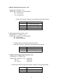
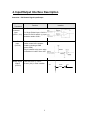
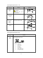
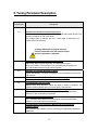
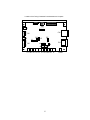
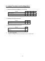
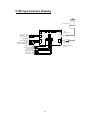
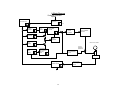
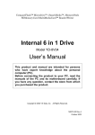
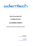
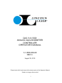
GAC 3.0-1XXX ANALOG GALVANOMETER CONTROLLER OPERATOR’S MANUAL 1-1-3500-950-00 REV C August 14, 2014 Please check with Lincoln Laser for the latest version of this Operator’s Manual *Subject to change without notice* 1 Table of Contents Introduction ▪ ▪ ▪ ▪ ▪ ▪ ▪ ▪ ▪ ▪ ▪ ▪ ▪ ▪ ▪ ▪ ▪ ▪ ▪ ▪ ▪ ▪ ▪ ▪ ▪ ▪ ▪ ▪ ▪ ▪ 3 1. Specifications ▪ ▪ ▪ ▪ ▪ ▪ ▪ ▪ ▪ ▪ ▪ ▪ ▪ ▪ ▪ ▪ ▪ ▪ ▪ ▪ ▪ ▪ ▪ ▪ ▪ ▪ ▪ 4 2. Description of Driver ▪ ▪ ▪ ▪ ▪ ▪ ▪ ▪ ▪ ▪ ▪ ▪ ▪ ▪ ▪ ▪ ▪ ▪ ▪ ▪ ▪ ▪ ▪ ▪ ▪ 5 3. I/O Connector ▪ ▪ ▪ ▪ ▪ ▪ ▪ ▪ ▪ ▪ ▪ ▪ ▪ ▪ ▪ ▪ ▪ ▪ ▪ ▪ ▪ ▪ ▪ ▪ ▪ ▪ ▪ 6 4. Input / Output Interface Description 5. Tuning Parameter Description ▪ ▪ ▪ ▪ ▪ ▪ ▪ ▪ ▪ ▪ ▪ ▪ ▪ ▪ ▪ ▪ ▪ ▪ ▪ ▪ 11 6. Jumper Function and Configuration 7. Outline Drawing ▪ ▪ ▪ ▪ ▪ ▪ ▪ ▪ ▪ ▪ ▪ ▪ ▪ ▪ ▪ ▪ 9 ▪ ▪ ▪ ▪ ▪ ▪ ▪ ▪ ▪ ▪ ▪ ▪ ▪ ▪ ▪ ▪ 14 ▪ ▪ ▪ ▪ ▪ ▪ ▪ ▪ ▪ ▪ ▪ ▪ ▪ ▪ ▪ ▪ ▪ ▪ ▪ ▪ ▪ ▪ ▪ ▪ ▪ ▪ 15 8. Wiring Connection Drawing 9. Functional Block Diagram ▪ ▪ ▪ ▪ ▪ ▪ ▪ ▪ ▪ ▪ ▪ ▪ ▪ ▪ ▪ ▪ ▪ ▪ ▪ ▪ ▪ 16 ▪ ▪ ▪ ▪ ▪ ▪ ▪ ▪ ▪ ▪ ▪ ▪ ▪ ▪ ▪ ▪ ▪ ▪ ▪ ▪ ▪ ▪ 17 2 Introduction This manual stipulates the Specifications, Input/Output Interface and Cautions about t h e GAC 3.0 series driver for Lincoln Laser supplied galvanometers. Please read this Operator’s Manual carefully to fully understand the specifications and safe operation of the product before use. The driver and galvanometers not only malfunction, but could cause damage if they are used improperly. Keep this manual handy for your reference even after you think that you fully understand the contents. :This marking indicates general dangers, warnings and cautions. Danger: Dangerous consequences, including death, serious injury, and fatal damage to your property could arise if you don't follow the instructions during operation of your equipment. Warning: Possible dangerous consequences, including death, fire, serious injury, a n d serious damage to your property could arise if you don't follow the instructions during operation of your equipment. Caution: Indirect consequences, including mild and moderate injuries and partial damage to your property could arise if you don't follow the instructions during operation of your equipment. Caution: Galvanometers and Controllers MUST be operated at the same voltage used to perform the factory tuning or damage may result to the Motor and/or the Controller. Galvanometers and Controllers are tuned as a matched pair, failure to operate as a pair may result in damage to the Motor and/or Controller. Tuning voltage and paired serial numbers can be found on the Galvanometer Final Inspection Data Sheet Attention: DO NOT REPRINT THIS USER MANUAL WITHOUT OUR PERMISSION. INSTRUCTIONS AND INFORMATION CONTAINED IN THIS MANUAL ARE SUBJECT TO CHANGE FOR UPDATING. 3 1. Specifications 1. Model: GAC 3.0 – 1XXX 2. Application: Lincoln Laser Galvanometer Scanner PHX Series 3. Main Specifications: -Input Voltage: ±15 to ±24VDC ±10% (Capable of supplying ≥ 5Amps is recommended) 1 1 Alteration of the Power Supply Voltage may require retuning of the system -Drive Principle: Linear Drive - Zero Position Hold Current: ≈ +160mA, -120mA -Max Output: ≈ 240W 4. Input Signal: -Position Command Input: Voltage Range ±3.0V p-p or ±10.0V p-p (Differential Input) (Single ended input is possible) 5. Output Signal: -Position Signal Output: Position Command Input and Position Signal Output voltage ranges are the same. 6. Protective Functions: Overheat Over-position Over-current Sensor malfunction 7. Ambient Operating Conditions: -Temperature: 0° C to + 50° C -Humidity: Non condensing, 10% to 85% RH 8. Configuration: -Construction: -Outside Dimension: -Weight: Open Frame Type 93mm long x 57.5mm wide x 31.0mm high 60g (with heat sink) 9. Accessories: -Connector (cable-side) Header CN1: DF1B-4S-2.5R Power Supply 1 pc Header CN3: DF1B-5S-2.5R Control Signal I/O 1 pc Contact pin: DF1B-2428SCA 12pcs * For AWG 24 Wire * Crimp Tool not included. 4 2. Description of Driver This product is a position-controlling s e r v o to linearly drive the galvanometers supplied by Lincoln Laser. This driver cannot be used with the galvanometers made by other companies Caution: Do not remove the heat sink from the driver when you use it, damage from overheating could result. 5 3. I/O Connector 1. Connector - CN1 Power Input Manufacturer: Hirose Electric Co. LTD Model #: DF1B-4P-2.5SA (01) (For board-side) DF1B-4S-2.5R DF1B2428SCA (For cable-side) (For cable-side) # 24 AWG is the recommended minimum cable wire size The connector pins should be crimped to the cable using t h e m a n u f a c t u r e r s recommended crimp tool Terminal # 1 2 3 4 Signal / Function FG DC + Power input GND DC - Power Input CAUTION: Do not exceed the maximum rated voltage. Reversal of voltage polarities will result in damage to the controller. 2. Connector - CN2 Position Sensor Input Manufacturer: Hirose Electric Co. Ltd. Model #: DF1B - 10DP - 2.5DS (01) DF1B - 10DS - 2.5RC (board-side) (galvanometers optical scanner-side) DF1B - 2428SCA Terminal # 1 2 3 4 5 6 7 8 9 10 (galvanometers optical scanner-side) Signal / Function Position Signal Input 1 Position Signal Input 2 GND GND AGC Frame Ground Frame Ground Frame Ground (-) motor winding (+) motor winding Connect only with galvanometer scanners supplied by Lincoln Laser. Not for use with scanners made by other companies. 6 3. Connector - CN3 Control Signal Input/Output Manufacturer: Hirose Electric Co. LTD Model #: DF1B-5P-2.5DSA (01) (board-side) DF1B-5S-2.5R DF1B-2428SCA (cable-side) (cable-side) Please refer to Section 4 (page 9) for the details of the Input/Output interface. # 22 AWG is the recommended minimum cable wire size The connector pins should be crimped to the cable using t h e m a n u f a c t u r e r ’ s recommended crimp tool Terminal # 1 2 3 4 5 Signal / Function + Position Command Input - Position Command Input GND Servo Enable Input Ready Output 4. Connector CN4 - Motor Connector Manufacturer: J. S. T. Mfg. Co. Ltd. Model #: B3PS - VH VHR - 3N (board-side) (galvanometer side) Supplies the voltage to drive the galvanometer. Not Applicable to Models PHX 030, 050, 075 The connector is UL-approved (File No. E60389) and CSA-approved (File No. 20812) Recommended wire size is # 16 to # 22 AWG Terminal # 1 2 3 Signal / Function Frame Ground - pole of motor winding + pole of motor winding Connect only with galvanometer scanners supplied by Lincoln Laser. Do not connect with scanners made by other companies. Manual crimping tools for the accessory connectors on the cable-side for CN1 and CN3 are available. (Not provided with this driver). Model AP105-DF1B2428S DF1B-TA2428SHC 7 5. Monitor Signal Output Connector - CN5 Manufacturer: JST Mfg. Co. Ltd. Model #: RE - H (04) 2TD - 1130 (board-side) RE - 02 (cable-side) RE - 02 (cable-side) Please refer to Section 4 (page 9) for the details of Input/Output interface. Terminal # 1 2 3 4 Signal / Function + Position signal output Scanner current output Position error output Speed output 6.Monitor Signal Output Connector - CN6 Manufacturer: J. S. T. Mfg. Co. Ltd. Model #: RE - H (02) 2TD - 1130 (board-side) RE - 02 (cable-side) RF - SC2210 (cable-side) An Alarm pulse is present when a fault has occurred. Please refer to Section 4 (page 9) for the details of Output interface. Terminal # 1 2 Signal / Function Alarm pulse output GND 7.Monitor Power Supply Output Connector - CN7 Manufacturer: J.S.T. Mfg Co Ltd. Model #: RE - H (02) 2TD - 1130 RE - 02 RF - SC2210 (board-side) (cable-side) (cable-side) +/-12VDV Power Supply Output Monitor Signal. Capable of sourcing 300mA (Max) Terminal # 1 2 Signal / Function DC +12V Power output DC -12V Power output 8 4. Input/Output Interface Description Connector - CN3 Control Signal Input/Output Signal Name Terminal # Position Command Input (CN 3-1, 3-2) Function Interface Input Command Voltage. For Single Ended Input, CN3-2 is shorted to CN3-3 and the (+) input should be made to CN3-1. Servo Enable Input (CN 3-4) This command enables position control of the scanner. Enable by shorting to GND (Active LOW). Gain is lowered at the servo when not Enabled. It Is NOT Servo OFF. Ready Signal Output (CN 3-5) LOW level w i t h n o F a u l t . HI level (+5V) in Fault condition. CN3-5 9 100ohm HC14 Monitor Signal Output Connector - CN5 Signal Name Terminal # Position Signal Output (CN5-1) Function Scale: 1/2 Actual voltage. Position Error Output (CN5-3) 15k Ω 1k Ω Caution: This terminal must connected to GND. Scanner Current Signal Output (CN5-2) Interface - CN5-1 not be 20k Ω Position signal output + 10kΩ Scale: 1volt = 1 amp - CN5-2 Scanner current Signal output Error level between Input Command and Motor Position CN5-3 Position error output Speed Output (CN5-4) 1k Ω 10k Ω 10k Ω 10k Ω - 10k Ω + 10k Ω CN5- 4 Speed output 1k Ω + - 10k Ω + Monitor Signal Output Connector - CN6 Signal Name Terminal # Alarm Pulse Output (CN6-1) Function Alarm pulse is present when a f a u l t h a s occurred. The number of pulses indicates the type of fault. Pulse Pulse(s) 1 … 2 … 3 … 4 … 5 … 6 … Fault Type Sensor error Over current Over heat Over position Power voltage error Over position (latch) 10 5. Tuning Parameter Description Potentiometer Description PS Adjustment of Position Command Input Scale You can adjust the voltage scale of the Position Input and Position Output. This will also fine adjust the max scan angle. The voltage scale is reduced (the m a x scan angle is reduced) as it is turned in the CCW direction. A voltage differential may appear between Position Command Input and Position Output when this parameter is adjusted. SRL EG SG EL Adjustment of the Position Command Slew Rate. Adjusts the Slew rate for a large step. The response increases when it is turned to CCW direction. The maximum rate will depend on the load inertia and power supply current capacity. Adjustment of Position Deviation amplifier Adjusts acceleration of scanner. Acceleration is increased when turned in the CW direction. Adjustment of the Proportional Gain of the Position Signal The leading overshoot can be reduced at position stabilization. Fine Adjustment of Error Limiter Adjusts Large step response. Please use when P control is selected. The response speed increases when it is turned in the CCW direction. LFD Adjustment of the Derivative Gain of the Position Signal The overshoot and undershoot can be reduced at position stabilization. Effective for the low frequency component. HFZ Adjustment of Current Integral Gain The overshoot and undershoot can be reduced at position stabilization. Effective for the high frequency component. HFD Fine Adjustment of the Frequency Band for the Current Integral Feedback Signal The overshoot and undershoot can be reduced by fine adjustment at position stabilization. 11 NF Adjustment of Notch Filter Center Frequency The center frequency of t h e notch filter can be adjusted to reduce the effects of shaft/mirror resonance. The center frequency is lowered when turned in the CW direction PF Adjustment of Position Signal Filter Circuit Adjusts Position Signal Filter – this will also alter the max scan angle. Please Contact Lincoln Laser before making this adjustment, since it will affect other factory settings. LIN Non linearity is adjustable no more than 10% for your scanner combination. 12 Location of the Tuning Parameter Potentiometers and Jumpers. CN5 J7 4 3 2 1 CN4 CN1 J2 5 4 3 2 1 1234 CN3 J1 CN6 2 1 CN7 J3 321 J4 2 1 CN2 123 J8 J6 J5 PS SRL EG SG EL LFD HFZ HFD NF PF 13 LIN 6. Jumper Function and Configuration 1. Position Command Input Limit Menu (J1, J2, J3 and J6) Function Slew rate limiter Slew rate limiter and S shape circuit Error limiter (for P control only) 2. P control PI control J4 1-2 2-3 J5 open short J3 open short -- J6 open open short GND and Frame Ground Connection (J7) J7 Function 4. J2 short short open Switching Control System (J4 and J5) Function 3. J1 1-2 1-2 2-3 GND-FG (connected when shipped from our factory) short GND-FG (not connected) open J8 – Not user adjustable Please do not change, as this is for Lincoln Laser use only. It is setup as short. 14 7. Outline Drawing (Dimensions in mm) 15 8. Wiring Connection Drawing Galvanometer ※ CN4 Motor Drive CN5 1234 Power input - 24V Power input GND Power input +24V Ready Output Servo Enable Input GND - Position Command Input + Position Command Input N.C. 4 3 2 CN1 1 CN6 2 1 5 4 3 CN3 2 1 CN7 2 1 CN2 Position Sensor Alarm pulse output GND Position Signal Output Scanner Current Position error output Speed signal output ※ CN4 is not used for PHX 030, 050, 075 Power output +12V Power output - 12V 16 9. Block Diagram Position Command Input Slew Rate Limit Circuit C o mm a n d G a I n Adjustment PS SRL + Position Amplifier - EG Servo Gain Adjustment Notch Filter Circuit Error limiter EL - SG + - Power Amplifier Circuit Current Amplifier + Speed Amplifier + Low Frequency Range Damping + NF - G al v an n o m e t e r LFD - Current Detection Resistance Adjustment of High Frequency Dumping Band High Frequency Range Damping HFD Current Detection Circuit HFZ Sensor Sensor Signal Processing Circuit Sensor Signal Filter Circuit PF 17 Your contact D-A-CH Laser 2000 GmbH 82234 Wessling Phone +49 8153 405-0 E-Mail [email protected] www.laser2000.de NORDICS Laser 2000 GmbH 112 51 Stockholm Phone +46 8 555 36 235 E-Mail [email protected] www.laser2000.se FRANCE – Photonic Laser 2000 SAS 33600 Pessac Phone +33 5 57 10 92 80 E-Mail [email protected] www.laser2000.fr FRANCE – Telecom Laser 2000 SAS 78860 Saint-Nom la Bretèche Phone +33 1 30 80 00 60 E-Mail [email protected] www.laser2000.fr IBERIA Laser 2000 SAS 28034 Madrid Phone +34 650 529 806 E-Mail [email protected] www.laser2000.es