1
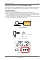
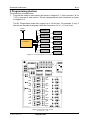
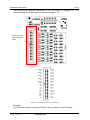
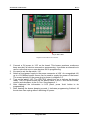
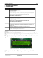
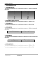
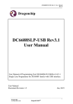
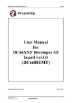
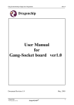
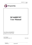
DC6688SLP-USB Manual
Rev1.1
User Manual
for
DC6688SLP-USB
Document Revision 1.1
Jan, 2009
Dragonchip
We bring silicon to life
DragonFLASH
TM
1
DC6688SLP-USB Manual
Rev1.1
Revision History
The following table shows the revision history for this document.
Date
Aug, 2008
Jan, 2009
Document
Revision
1.0
Preliminary
1.1
Added DC6688F2SCN
Remark
Dragonchip
We bring silicon to life
DragonFLASH
Edited By
Kennis To
Ken Yeung
TM
Reviewed
By
Danny Ho
Danny Ho
2
DC6688SLP-USB Manual
Rev1.1
Contents
DOCUMENT REVISION 1.1
JAN, 2009 ......................................................................................................... 1
1 INTRODUCTION ................................................................................................................................................ 4
2 DOWNLOAD CODE FROM PC TO DC6688SLP-USB ............................................................................... 5
2.1 HARDWARE SETUP .......................................................................................................................................... 5
2.2 SOFTWARE SETUP ........................................................................................................................................... 6
3 PROGRAMMING DEVICES............................................................................................................................. 7
4 HARDWARE DESCRIPTION......................................................................................................................... 10
4.1 FUNCTION KEYS ............................................................................................................................................ 10
4.2 WHERE DOES THE CODE STORE? ................................................................................................................... 11
4.3 MAXIMUM POWER TO DEVICE ...................................................................................................................... 11
4.4 LCD PANEL .................................................................................................................................................. 11
4.5 CONNECTION TO DEVICE ............................................................................................................................... 11
4.6 VARIABLE RESISTOR ON THE BOARD ............................................................................................................ 11
5 PROGRAMMING TIME................................................................................................................................... 12
5.1 DC6688FSA/FSB ........................................................................................................................................ 12
5.2 DC6688FL32A/DC6688FLB....................................................................................................................... 12
5.3 DC6688F05S ............................................................................................................................................... 12
5.4 DC6688FSX................................................................................................................................................. 12
5.5 DC6688FLX ................................................................................................................................................ 12
5.6 DC6688F2SCN............................................................................................................................................ 12
Dragonchip
We bring silicon to life
DragonFLASH
TM
3
DC6688SLP-USB Manual
Rev1.1
1 Introduction
The Objective of this document is to provide the user a quick start to evaluate
DC6688SLP-USB. This board is applicable to the following:
1) DC6688F05S
2) DC6688FSA
3) DC6688FSB
4) DC6688FLB
5) DC6688FL32A
6) DC6688FLX
7) DC6688FSX
8) DC6688F2SCN
To program the DC6688 family, it involves 2 steps:
a) Download code from PC to DC6688SLP-USB refer to section 2 for detail
b) Program DC6688 family in each device refer to section 3 for detail
Section 4 describes the hardware in detail.
Dragonchip
We bring silicon to life
DragonFLASH
TM
4
DC6688SLP-USB Manual
Rev1.1
2 Download code from PC to DC6688SLP-USB
To download the code to DC6688SLP-USB, it involves the hardware and software
setup. Setting up the hardware first, and then use software to control the download.
2.1 Hardware setup
The procedure is listed below:
a) Connect the board via a USB2.0 cable to PC as shown in diagram 2.1
b) Attach a fixed power supply to the power-connector at ‘J24’. An unregulated +9V
up to +12V/800mA power source can be used to supply the power of the board.
The correct polarity of the power plug is shown in diagram 2.2.
c) Turn on the switch ‘J25’. The LED ‘D16’ should be turned on to indicate the board
is ready. The on/off position is shown in diagram 2.3
PC
To USB port
in PC side
DC6688SLP-USB
Diagram 2.1 Connection between SL
Programmer board and PC
+ve (inside)
Polarity : -ve (outside)
Diagram 2.2 Polarity of DC Jack
Diagram 2.3 On/Off position of power
switch
Dragonchip
We bring silicon to life
DragonFLASH
TM
5
DC6688SLP-USB Manual
Rev1.1
2.2 Software setup
The software setup needs ‘Dragonchip ISP Programmer’ with version 4.7.0 or higher.
Details on setup and how to use the software to download code refer to the file
“Help.chm” in the package of the software. This software downloads the code to
DC6688SLP-USB.
After downloading the code, press the Reset button once.
Dragonchip
We bring silicon to life
DragonFLASH
TM
6
DC6688SLP-USB Manual
Rev1.1
3 Programming devices
The procedure is listed below:
1. Connect the board to each device as shown in diagram 3.1. Use connector ‘J6’ to
‘J15’ to connect to each device. The pin assignment on each connector is shown
in diagram 3.2.
The SL Programmer board can support up to 10 devices. For example, if only 6
devices are needed to program, then the connectors ‘J6’ to ‘J11’ are used.
Buzzer
Device 1
Device 2
Device 3
Device 4
Device 5
DC6688SLP
Device 6
Device 7
Device 8
Device 9
Device 10
Diagram 3.1 Connection between SL Programmer board and device
GND
SL
PWR
GND
SL
PWR
GND
SL
PWR
GND
SL
PWR
GND
SL
PWR
GND
SL
PWR
GND
SL
PWR
GND
SL
PWR
GND
SL
PWR
GND
SL
PWR
Diagram 3.2 Pin assignments for each
connector ‘J1’ – ‘J10’
Dragonchip
We bring silicon to life
DragonFLASH
TM
7
DC6688SLP-USB Manual
Rev1.1
The devices can also be connected to ‘J21’ as shown in diagram 3.3. It is
recommended to use IDE cable as shown in diagram 3.4.
Remove this pin
when using IDE
cable
CLK[1]
NC
CLK[1]
NC
CLK[1]
NC
CLK[1]
NC
CLK[1]
GND
NC
NC
NC
NC
VCC
VCC
VCC
VCC
VCC
NC
GND
D1 SL
D2 SL
D3 SL
D4 SL
D5 SL
D6 SL
D7 SL
D8 SL
NC
GND
GND
GND
NC
GND
D9 SL
D10 SL
NC
NC
GND
Diagram 3.3 Connection between ‘J21’ and devices
Remarks:
[1] CLK must connect to device’s XIN pin. One pin shares to two Devices.
Dragonchip
We bring silicon to life
DragonFLASH
TM
8
DC6688SLP-USB Manual
Rev1.1
40-pin IDE cable
Diagram 3.4 IDE cable on the connector
2.
3.
4.
5.
6.
7.
Connect a 3V buzzer to ‘J23’ on the board. This buzzer produces continuous
beep sounds if all devices succeed on programming. It provides an alternative to
user a notice that one or more devices fail on programming.
No need to set the dip switch ‘J16’.
Attach a fixed power supply to the power-connector at ‘J29’. An unregulated +9V
up to +12V/800mA power source can be used to supply the power of the board.
The correct polarity of the power plug is shown in diagram 2.2.
Turn on the switch ‘J25’. The LED ‘D16’ should turn on to indicate the board is
ready. The LCD panel shows up the device name in the 1st line and the model,
version and checksum in the 2nd line. See diagram 4.1.
After displayed the information in LCD panel, press ‘Auto’ button to do
programming.
After hearing the buzzer beeping sounds, it indicates programming finished. All
the devices can unplug without switching off power.
Dragonchip
We bring silicon to life
DragonFLASH
TM
9
DC6688SLP-USB Manual
Rev1.1
4 Hardware description
4.1 Function keys
Keys
Description
Auto
This key performs
a) write code to device,
b) read back the code from device,
c) verify the code[2],
d) if ‘Lock’ option[4] is selected, lock the device preventing from reading back
From step a to d, the LED corresponding to a device will flash.
If the result success, the LED turns on.
If the result fails, the LED turns off.
Verify
This key performs
a) read back the code from device,
b) verify the code[2]
From step a to b, the LED corresponding to a device will flash.
If the result success, the LED turns on.
If the result fails, the LED turns off.
CheckSum[1] This key performs
a) read back the Model, Version, Checksum in flash memory on device 1 (i.e.
connector “J6”)
b) display the Model, Version, Checksum on the LCD panel [3].
Reset
This key, when pressed, will reset the board to initial state without turn off/on
the power. When ready, the LED ‘D16’ turns on.
Remarks:
[1] Only device 1 will be read for checksum.
[2] Verify the code by comparing byte by byte. If at least one byte fails, the LED will be
off.
[3] The device name and Model:Version:Checksum display are shown below:
When Checksum button is pressed, the information of Device 1 will be read and ‘:’
sign will become ‘_’ sign.
Diagram 4.1 Device name in the 1st line and Model:Version:Checksum in the 2nd line
[4] This option is set in software ISP, no longer available on dip switch “J16”.
Dragonchip
We bring silicon to life
DragonFLASH
TM
10
DC6688SLP-USB Manual
Rev1.1
4.2 Where does the code store?
When PC downloads the code to the DC6688SLP-USB, the code is stored to the
flash memory ‘U6’ (AT29LV010A).
4.3 Maximum Power to device
DC6688SLP-USB can support up to 10 devices. The maximum current to supply by
regulator ‘J25’ to the 10 devices simultaneously is 800mA.
4.4 LCD Panel
The SL Programmer Board can provide display of model, version and checksum to
identify the source code.
When power on, the display will show up the checksum for the code stored at the
flash memory ‘U6’ (AT29LV010A). The checksum is consistent with the one shown in
the software ISP Programmer V4.3.0 or higher.
4.5 Connection to device
From J6 to J15, AWG#26 wire is recommended for power line. The wire, which the
thickness is too thin, is not appropriate.
From J6 to J15, AWG#28 wire is recommended for SL line.
4.6 Variable Resistor on the board
Do not change the turns of the three variable resistors ‘R35’ ‘R37’ and ‘R51’ on the
board.
Dragonchip
We bring silicon to life
DragonFLASH
TM
11
DC6688SLP-USB Manual
Rev1.1
5 Programming Time
5.1 DC6688FSA/FSB
The maximum programming time for each device operating at 12MHz is shown in the
table below:
Program Size/kbytes
2
4
8
14
16
24
30
Programming time/s
1.32
1.32
1.58
2.46
2.46
3.46
4.2
5.2 DC6688FL32A/DC6688FLB
The maximum programming time for each device operating at 12MHz is 4.52s
5.3 DC6688F05S
The maximum programming time for each device operating at 4MHz is 3.68s
5.4 DC6688FSX
The maximum programming time for each device operating at 12MHz is shown in the
table below:
Devices
DC6688F62SX/SXE/SXR
Programming time/s
8.14
5.5 DC6688FLX
The maximum programming time for each device operating at 12MHz is shown in the
table below:
Devices
DC6688FL64X/XE
Programming time/s
8.4
5.6 DC6688F2SCN
The maximum programming time for each device operating at 12MHz is 1.32s
The maximum programming time for each device operating at 4MHz is 1.60s
Dragonchip
We bring silicon to life
DragonFLASH
TM
12
DC6688SLP-USB Manual
Rev1.1
Copyright Notice
This specification is copyrighted by Dragonchip Ltd. No part of this specification may be reproduced in
any form or means, without the expressed written consent Dragonchip Ltd.
Disclaimer
Dragonchip Ltd. assumes no responsibility for any errors contained herein.
Copyright by Dragonchip Ltd. All Rights Reserved.
Dragonchip Ltd.
TEL: (852) 2776-0111
FAX: (852) 2776-0996
http://www.dragonchip.com
Dragonchip
We bring silicon to life
DragonFLASH
TM
13