1
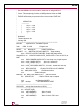
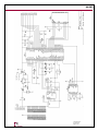
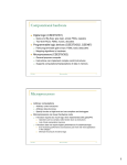
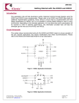
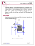
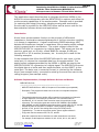
AN 002
Interfacing the KXP94 or KXR94 Tri-Axis Accelerometer
with the Texas Instruments MSP430F149
Microprocessor to Measure Tilt and Other Motions
This application report describes how to integrate the Kionix KXP94 or the
KXR94 tri-axis accelerometer with the MSP430F149 to capture and utilize the
motion sensing capabilities of the accelerometer. Example code is provided
for capturing and using tilt sensing, vibration sensing and acceleration.
Source code is provided for the MSP430F149 as well as source code for the
demonstration software drivers and applications.
Introduction
Kionix linear accelerometers function on the principle of differential
capacitance. Acceleration causes displacement of a silicon structure resulting
in a change in capacitance. A signal-conditioning CMOS technology ASIC
detects and transforms changes in capacitance into an analog output voltage
which is proportional to acceleration. The output voltage is sent to the
MSP430F149 ADC for conversion to a digital signal. This signal can then be
sent to a serial port, an IR chip, a flash NAND for storage, a USB port,
through SPI or I2C to another processor, etc. A serial port is used for the
following examples.
In the examples that follow the MSP430F149 waits for user input, via the
serial port, to retrieve the requested data from the accelerometer. The
analog output voltages generated by the KXP94 or KXR94 are sent to the
MSP430F149 ADC for conversion to a digital signal. The MSP430F149 moves
the digital data to a buffer and then sends the data, via the USART, to the
serial port. The data, now in numerical format, is received by the software
driver (see example code), converted to actual g-force and then sent to the
calling program (see example code).
Software Implementation, Example Software Drivers and Demos
MSP430F149 Code
;******************************************************************************
; MSP-FET430P140 Demo - ADC12, Sequence of Conversions (non-repeated)
;
; Description: This program will show how to convert a non-repeated sequence
;
of channels.
;
; This example shows how to perform A/D conversions on a sequence of channels.
; A single sequence of conversions is performed - one conversion each on
; channels A0, A1, A2, and A3. Each conversion uses AVcc and AVss for the
; references. The conversion results are stored in ADC12MEM0, ADC12MEM1,
; ADC12MEM2, and ADC12MEM3 respectively and are moved to R5, R6, R7, and R8
; respectively after the sequence is complete. Test by applying voltages to
; pins A0, A1, A2, and A3, then setting and running to a break point at
; "jmp Mainloop." To view the conversion results, open a register window in
; C-Spy and view the contents of R5, R6, R7, and R8.
;
; Note that a sequence has no restrictions on which channels are converted.
; For example, a valid sequence could be A0, A3, A2, A4, A2, A1, A0, and A7.
36 Thornwood Dr. – Ithaca, NY 14850
tel: 607-257-1080 – fax: 607-257-1146
www.kionix.com - [email protected]
© Kionix 2007
5 June 2007
Page 1 of 1
AN 002
; See the MSP430x1xx User's Guide for instructions on using the ADC12.
;
; *Note* This example only functions on MSP production silicon, not PMS
; pre-production silicon. Production silicon will be noted on the chip as
; "M430F149" whereas pre-production silicon will be marked "P430F149."
;
;
;
MSP430F149
;
----------------;
|
|
;
|
A0 |<---- Vin0
;
|
A1 |<---- Vin1
;
|
A2 |<---- Vin2
;
|
A3 |<---- Vin3
;
|
|
;
;
; M.Mitchell
; Texas Instruments, Inc
; January 2004
;******************************************************************************
#include
"msp430x14x.h" // Standard Equations
;-----------------------------------------------------------------------------main
ORG 01100h
; Program Start
;-----------------------------------------------------------------------------RESET
mov #0A00h,SP
; Initialize stackpointer
StopWDT mov #WDTPW+WDTHOLD,&WDTCTL ; Stop watchdog
bis.b #BIT0+BIT1+BIT2+BIT3,&P6SEL ; Enable A/D channel inputs
;
SetupADC12 mov #ADC12ON+MSC+SHT0_2,&ADC12CTL0 ; Turn on ADC12, set
MSC
mov #SHP+CONSEQ_1,&ADC12CTL1 ; Use samp. timer, single sequence
bis.b #INCH_0,&ADC12MCTL0
; AVcc=ref+, channel=A0
bis.b #INCH_1,&ADC12MCTL1
; AVcc=ref+, channel=A1
bis.b #INCH_2,&ADC12MCTL2
; AVcc=ref+, channel=A2
bis.b #INCH_3+EOS,&ADC12MCTL3 ; AVcc=ref+, channel=A3, end seq.
;
mov #BIT3,&ADC12IE
; Enable ADC12IFG.0 for ADC12MEM0
bis #ENC,&ADC12CTL0
; Enable conversions
eint
; Enable interrupts
;
Mainloop bis #ADC12SC,&ADC12CTL0
; Start conversions
bis #CPUOFF,SR
; Wait in LPM0 for seq to complete
;
nop
; Only Required for CSPY
jmp Mainloop
; SET BREAKPOINT HERE
;
;-----------------------------------------------------------------------------ADC12ISR ; Interrupt Service Routine for ADC12
;-----------------------------------------------------------------------------bic #CPUOFF,0(SP)
mov &ADC12MEM0,R5
; Move A0 result
mov &ADC12MEM1,R6
; Move A1 result
mov &ADC12MEM2,R7
; Move A2 result
mov &ADC12MEM3,R8
; Move A3 result, IFG is reset
reti
;
© Kionix 2007
5 June 2007
Page 2 of 2
AN 002
;
;-----------------------------------------------------------------------------;
Interrupt Vectors
;-----------------------------------------------------------------------------ORG 0FFFEh
; MSP430 RESET Vector
DW
RESET
;
ORG 0FFEEh
; ADC12 Interrupt Vector
DW
ADC12ISR
;
END
Software Driver
Example Pseudo-code For Retrieving An Acceleration Reading
SerialPort.send(“x”)
// For this example, the requested axis will be X
Reading = SerialPort.recieve(2 bytes)
// Value is sent as a 2-byte integer
Voltage = Reading/4096
// This ratio is defined by the A/D converter
Acceleration = (Voltage*1000)/Sensitivity
// Sensitivity is in mv/g
Acceleration -= AdjustmentX
// Center reading based on earlier calibration
return Acceleration
// Acceleration is returned in g's
Hardware Implementation
Kionix has designed and built a small development board that interfaces a
KXP94 or KXR94 with the Texas Instruments MSP430F149. The KXP94-DEVV1 (KXP94-2050 Development Board) or the KXR94-DEV-V1 (KXR94-2050
Development Board) allows users to rapidly develop motion based
applications using the processing capabilities of the MSP430F149. boards
and evaluation boards are available at
http://www.kionix.com/sensors/evaluation-kits.html. The schematic for the
KX_94-DEV-V1 is shown on the following page.
© Kionix 2007
5 June 2007
Page 3 of 3
AN 002
© Kionix 2007
5 June 2007
Page 4 of 4
AN 002
Software Demos for the Development Board
A variety of small applications which work with the development board and
will run on a Windows-based PC is available at
http://www.kionix.com/sensors/downloads.html. Download the latest version of
the file named Kionix Demonstration Software. An executable installer will
install the demonstration software on your computer.
For more information about how to use the software with the development
board, please refer to the User’s Manual for the KX_94-DEV-V1 Development
Board available at http://www.kionix.com/sensors/evaluation-kits.html.
Theory of Operation
Kionix MEMS linear tri-axis accelerometers function on the principle of
differential capacitance. Acceleration causes displacement of a silicon
structure resulting in a change in capacitance. A signal-conditioning CMOS
technology ASIC detects and transforms changes in capacitance into an
analog output voltage which is proportional to acceleration. These outputs
can then be sent to a micro-controller for integration into various
applications. Kionix technology provides for X, Y and Z-axis sensing on a
single, silicon chip. One accelerometer can be used to enable a variety of
simultaneous features including, but not limited to:
•
Drop force modeling for warranty management
•
Hard disk drive shock protection
•
Tilt screen navigation
•
Theft, man-down, accident alarm
•
Image stability, screen orientation
•
Computer pointer
•
Navigation, mapping
•
Game playing
For product summaries, specifications, and schematics, please refer to the
Kionix accelerometer product sheets at
http://www.kionix.com/sensors/accelerometer-products.html.
© Kionix 2007
5 June 2007
Page 5 of 5