1
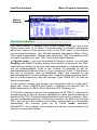
Performance Software
from InterFlex Systems Design
For AEA PK-88, PK-232, DSP-1232, DSP-2232
Kantronics KPC-2,KPC-3, KPC-4 and KAM Dual Port Versions
Requires MS DOS, and runs under Windows, Desqview, OS/2
PkGOLD & KaGOLD
Software Guide and User Manual
Published in Adobe Acrobat™ format
Manual covers PkGOLD, KaGOLD, dspGOLD PkGOLD/900
•
•
•
•
•
•
Installation Procedures
Operating Mode Descriptions
Software Operation
Program Reference
Customizing Options
New Features Explained
InterFlex™ Systems Design
Setting the Performance Standard for Digital Mode Software
GOLD, PkGOLD, KaGOLD, PkGOLD/900, dsp-GOLD, Packet-PLUS,
used in the context of digital mode communications software are names
and trademarks used by InterFlex Systems Design Corporation.
Copyright (C)1994..2001by InterFlex™ Systems Design Corporation
Post Office Box 6418
Laguna Niguel, CA 92607-6418
Web Page: http://www.interflex.com
The manual begins with a Welcome chapter on the next page.
InterFlex Systems
Welcome to PkGOLD/KaGOLD
Welcome to PkGOLD/KaGOLD
Thank you for choosing one of our advanced digital mode software
products. You will soon discover an array of unique and powerful
features that are easy to learn and use. The program does many things
for you automatically including memory management. You do not have
to decide about the number of scroll-back lines or size of the scroll-back
buffer as you do on some other programs. The buffer sizes are all handled dynamically, with memory used as it is needed, and returned to the
system when appropriate. No other digital mode program offers this
transparent, and fully automatic management of your system’s multiconnect scrollback memory.
Multi-Connect: The software also makes it easy to handle multiple
sessions. During packet mode operation, you can ignore the details of
which session is on which "channel" or "stream." The program does this
for you, so you can quickly become adept at handling multiple packet
QSOs without the confusion you may have experienced with other
software. The idea is simple: as text from another station arrives, the
software gives you a signal that another session needs attention and
provides you with a single keystroke [F4] to switch to that session. It
also saves the current text you may be typing, saves the QSO screen,
and pops in place the new screen for you. You can also switch from
session to session manually using [F4], or go directly to a particular
QSO using [Ctrl-Fn] keys. The easiest approach is to let the software
be your guide and do things automatically. Starting new sessions is also
easy: type a callsign and push [F7] the connect key. And for text
handling, no other program offers the huge scroll-back buffer sizes and
automatic session management capabilities of GOLD software.
Auto-Recognition: The automatic exchange of station information
(name, qth, and other information) in packet mode with other "GOLD"
users, which comes in handy when you work new stations. You don't
have to ask who they are, or where they are, it's done automatically.
Text Handling: Another advanced feature is the automatic saving of
QSO text to the "[F3] Previous Sessions" screen. After a packet
session, or after switching modes (for multi-mode TNCs) QSO text is
moved to a single screen called the "Previous Sessions" screen. This
feature allows you to have all of your prior QSOs in a single large buffer
area. You can print this screen to a printer and file to produce a
complete record of your QSOs. You can also use the [F5] clipboard to
1
InterFlex Systems
Welcome to PkGOLD/KaGOLD
copy parts of the buffer to the clipboard and then write the copied text to
a file, to the printer, or copy to another session. This and other text
operations are available on the [F5] menu.
Non-Packet support: On multimode TNCs, there are several features
that make operating RTTY, PACTOR, AMTOR and MORSE simple and
easy. These include [Alt-F1] Robot CQ mode, automatic logging,
[Alt-F6] Brag file support, automatic generation of AMTOR SELCALS
from ham callsigns when using the [F7] Connect key approach. You still
have all of the advantages of the packet mode including huge scrollback buffers, text handling, printing, and more.
Callbook support: The software has built-in support for four CD based
callbooks -- Buckmaster, AMsoft, QRZ, and SAM, (SAM is available as
disk or CD). Callbook data is displayed automatically in several
operating modes. In addition to automatic lookup, you can use [Alt-I]
and the SENDCALL command. See pages 19 and 75.
Callbook Server: You can setup your station to be a "callsign server" if
you wish. In packet mode, a remote user running any program, any
TNC, can connect to your station and request one or more callsign
lookups. See page 76.
Conference bridge: In Packet mode, several connected stations can
all converse with each other if you setup a conference using the [Alt-F1]
function and the [Insert] key to toggle the conference "tag" for a station.
You can even add another GOLD conference to your GOLD
conference (another station running PkGOLD or KaGOLD with a
conference) and create a "conference of conferences." This capability
to create a network of conferences is not done by many users, but it is
a capability built into the software. For Dual Port units, running
Packet on both ports, you can even have a cross-band
conference. See pages 59 to 61, 77 and 81.
Remote Conference commands: You can setup your station to
conference all new incoming connects, or let remote users decide to
join, or manually enter a station into your conference. A remote user
can check WHO is connected to your station, and JOIN a conference,
and even create a new conference. A remote user can also send a text
message directly to another station in the conference, without having it
broadcast to all the other members. Great for packet nets, emergency
communications, or general discussions among a group. Makes
keyboard to keyboard packet a new and more interesting experience.
Restartable File Transfers: YAPP binary file transfers are supported,
including remote controlled transfers and restartable transfers. A user
2
InterFlex Systems
Welcome to PkGOLD/KaGOLD
can connect, get a directory, and start an upload or download. Your
station can even be a file server of sorts, a place where binary and text
files can be deposited and retrieved by other users. See page 87.
ANSI Color/BW Graphics support:
You can switch between
interpreting incoming text in ANSI screen graphics mode with [Alt-G] or
in straight ANSI escape sequence mode. You will find ANSI graphics
available on the air, and on BBS systems. Many users exchange ANSI
graphics on HF using PACTOR, and with GOLD software, you will be
able to do it too. One of the differences with GOLD software is the
ability to interpret multiple screens of ANSI graphics, and on dual port
versions, get graphics from different ports, and even in different
modes (VHF Packet, HF Pactor). PkGOLD and KaGOLD may not be
the first programs to support ANSI color graphics, but they are the first
programs to do it on multiple sessions. See page 85. Or click this link to
go to ANSI Pics
Custom Remote Commands:. Allows you to develop batch-like files of
commands that are accessible to remote users. These CMD files can
set tnc parameters, start file transfers, send messages, and even
initiate connects. The capabilities of the CMD files is one of the new
features that advanced users will want to try. See pages 77 to 84.
Advanced access to your TNC: PkGOLD and KaGOLD give you
enormous flexibility and control over your TNC. You can issue TNC
commands directly, or issue them in batches with TNC files. You can
transmit and receive files while doing other tasks, even access the
maildrop while connected to other stations. While some users familiar
with the CMD: prompt may miss seeing it, we've put it on the [F10] key
for easy access. Type a parameter name and push [F10] to see the
current setting. Type DISPLAY [F10] and see groups of parameters.
Scroll back in the text, cut/paste text. It's all possible with PkGOLD and
KaGOLD. You will have more control over your TNC than available with
ANY other software. Examples occur throughout the manual.
Now that you have an idea about some of the capabilities of the
software, let's begin by installing the software and running it through
some tests on your computer. Then in the chapter after that, the
hardware is described and connected. Then we will cover the help
system. Finally, we will get into the details of each operating mode.
Review the directories used by PkGOLD and KaGOLD. Then turn to the
next chapter to install the software.
3
InterFlex Systems
Welcome to PkGOLD/KaGOLD
GOLD Directory Layout
This page contains a brief explanation of the file locations and directory
structure for the GOLD program and support files. Users of prior
versions will notice a difference, and new users will want to know where
to find certain files.
GOLD directory, e.g. PkGOLD or KaGOLD, contains the .EXE file, the
configuration file, and the .HLP (help) file. Off the main GOLD directory
are fhe following:
ANSFILES contains files saved during ANSI “picture” capture.
BRGFILES has files with .BRG extensions, such as CONNECT.BRG, and your
station description .BRG file if you create one.
CMDFILES has a collection of files with .CMD, and several are put in this
directory when you install the program, and you can add more commands.
TNCFILES has files with .TNC extension, which are text files with several TNC
commands, useful for switching modes, or reconfiguring your tnc. Here you will
find Startup.tnc and Shutdown.tnc.
DOWNLOAD has text and files that you write from the clipboard, or that are
sent to you by other users.
UPLOAD is the directory used when you start a file transfer. You can navigate
to other directories from this directory, but this is the starting point.
PRINT is the directory where data saved with [Alt-P] goes by default.
MONITOR is where monitored data goes if you enable “save monitored data to
disk” in the setup area of the program.
DOCFILES is an optional directory that may exist after installation, and have
additional files of interest. This directory is not needed to run GOLD, it may be
included as a source of additional information.
BONUS is another optional directory that may be included during install that
may contain programs of interest. It is not needed to run the program, but the
files in this directory may be of interest to some users.
Also in the main directory (KaGOLD, PkGOLD) you will find the log files,
GOLD.DB the database, and GOLD.DBI, the index. These log files are
created by the installer, and if an old version of the logs exists, the
installer will convert them to the new format. Starting with version 9, all
versions (for AEA and Kantronics tncs) use the same log file layout, so
GOLD.DB and GOLD.DBI created by PkGOLD can be used if you
switch to KaGOLD, and vice versa.
Information about TNC files, CMD files, BRG files, and the program
setup is in the rest of this manual. This page is intended to give you an
idea of what directories you will find after installation.
4
InterFlex Systems
Software Installation
Software Installation
For those in a hurry, simply insert the release disk, or better, a copy of
it, in a floppy drive and type INSTALL. There are very few questions to
answer. Most can be answered by taking the defaults presented on the
screen. If you want a more organized, step by step approach, follow the
installation steps that follow.
The TestDrive
Some users will find a TestDrive disk included with the software, or a
subdirectory on the disk labeled "Testdriv" or “Demo.” The TestDrive
consists of all of the files necessary to install the TestDrive program.
You may give copies of these files to anyone who is interested in the
program to let them learn more about the software and how it works.
You may want to install the test drive on your own system. The
TestDrive has a "Sound Demo" portion that is helpful in identifying the
various signals that can be heard, and decoded, on HF. It runs for 30
minutes at a time, and asks the same set of questions each time it
runs. It does NOT save any settings or data to disk between runs. The
TestDrive also has larger DOC files which you may find useful.
The release version saves settings, and comes on-line much faster.
Naturally, you will want to run the release version, but knowledge of the
TestDrive and how it works will help you explain the software to others,
and give you something to given other users if they ask for a copy of
PkGOLD or KaGOLD to check out.
Installing the Release Version
You can install and check out the software without a TNC. Later you
can hook up the serial port to the TNC and test the software and TNC
together. Then wire up the TNC to a radio speaker output and monitor
some digital activity. Last, hook up the microphone jack or FSK
connector (HF only) and make some "on-the-air" contacts. If you do
things in stages, you will be on the air quickly.
Make a Backup Copy
As with any new software, you should make a backup copy of the files
on the original disk before installing. We suggest using the DOS Copy
command. By copying the files you can assure that the disk files are
readable on your disk drive and that you have an archival copy of the
5
InterFlex Systems
Software Installation
files in case you damage the disk. You can copy the files from a 5.25"
disk to a 3.5" disk or vice versa if necessary. If you have two disk drives
is to put the release disk in A: and a blank disk in B: and type:
COPY A:*.* B:
If you are not familiar with DOS, ask a friend or consult your DOS
manual about how to copy files. We don't write anything to your diskette
so put a "write protect" on your 5.25" disk, or slide the plastic tab on
the 3.5" disk to expose the square hole.
Insert Disk, then type Install
Put the program disk (or disk 1 if a 2-disk install) into a disk drive, then
from that drive type INSTALL. If the installer loads and things seem to
be going smoothly, skip the following note.
Note: the installer requires about 450K of RAM memory to run, so if you
run a menu program, you may need to exit the menu program, and
return to DOS to run the installer.
The installer presents a screen telling you about the program. Read the
screen and hit [Enter] to continue. Use [Enter] to take defaults unless
you have a reason to override the them. Follow the on-screen
instructions.
Enter your Registration Number(s)
Look on the DISK label, or on the mailing label, or on some other
document for a user registration number. If you bought the program
from a retailer, look on the packaging for instructions to obtain a
registration number. Type in the first registration number carefully and
hit [Enter]. If you have additional numbers, enter them as prompted.
Initial Software Test
The installer leaves you in the GOLD subdirectory. If you switched to a
different directory, or rebooted the computer, you need to change to the
GOLD directory. For example, a PkGOLD user might type:
CD\PKGOLD f
The subdirectory name is typically the same name as the program file
name. If you have KaGOLD, the subdirectory should be called
KAGOLD. Like any DOS program, you must be in the right subdirectory
to run the program.
6
InterFlex Systems
Software Installation
Note: Advanced DOS users can add the drive:\directory name to the
PATH= command in Autoexec.bat. DOS will use this path= environment
variable to find and load the program.
Access the Help System from DOS: Run the program with the /H
switch to access the help system directly from DOS. You don't need a
TNC or Radio hooked up yet, just start the program with the /H switch.
For example, a KaGOLD user would type:
KAGOLD/H f
A PkGOLD or dspGOLD user would type the program name followed by
the /H switch. Navigate around the Help System, then use [ESC] to
back out of the help system and return to DOS. Other command line
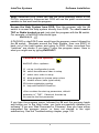
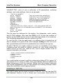
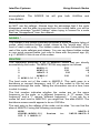
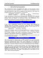
"switches" are shown if you type /? after the program name. Here is
what you might see by typing KaGOLD/?
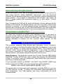
Command line options:
KaGOLD <file> <options>
/S set up (configuration) mode
/M select monochrome video in setup
/C select color video in setup
/D allow program to choose setup colors
/Q disable morse, bells (quiet mode)
/R # enter registration number
/H help with KaGOLD DualPort
<file> contains the start up parameters, default
extension is ".TNC". If desired, the start up
file must be the first parameter.
If you type the program name, followed by /H and the program loads
and brings you to the Help Index, you have successfully installed the
software. If you see “Bad Command or Filename” then you have either
misspelled the program name, or have not started in the right
subdirectory. See the Troubleshooting chapter, page 109.
7
InterFlex Systems
Software Installation
Using the Manual
The Table of Contents, and the Index are designed to allow you to find
answers to many of the questions you may have about the software and
about solving problems, both computer problems, tnc problems, and
software problems.
Note: If you find that the program operates differently than the manual
says it does, the ultimate authority on how the program should run is
the program itself.
Technical Support
Internet: Visit our web page http://www.interflex.com to get information
about the software, and more information on how to contact us with
questions or to place orders. The most productive way to get help is to
visit the web page.
Fax: With the advent of the internet, we have reduced our need to
handle fax messages. While we do have a fax machine, it is not used
for Technical Support.
Phone: This is convenient and quick if someone is available to take
your question, but you may get an answering machine or voice mail
system. We have moved all technical support and ordering to the
internet, to keep costs down and to make it more convenient for you as
well. You can download programs, and get news and help by visiting
the web page.
Mail: We welcome suggestions by mail, but this is not a good medium
for asking technical questions due to the lack of a reasonable dialog. A
timely exchange is necessary to determine the source of problems. In
our 10 year experience with PkGOLD and KaGOLD, we have found that
99% of the problems are due to hardware problems or software that is
conflicting with the serial ports. That number has risen over the years,
as we have done everything possible to make the software reliable, and
have introduced no major changes since 1998, with the exception of
supporting the fastest systems available. PkGOLD and KaGOLD will
run on systems over 1 Ghz in clock speed.
Now let’s turn to the next chapter and get the program running and
talking to your TNC.
8
InterFlex Systems
Basic Program Operation
Basic Program Operation
The best way to learn the basic keystrokes used in the program is to do
it, not just read about it. Follow through the next few pages to learn how
to startup the program, navigate through some of the basic functions,
and get back to DOS.
Starting the Program
You don't need to wire the radio to check out the TNC, but if you have
a radio hooked to the TNC, turn down the radio receiver volume.
This avoids "on the air" activity to interfere with the first time
initialization. Connect the TNC to a serial cable.
With the TNC on, run the program. A dspGOLD user would type:
DSPGOLD f or PkGOLD, KaGOLD...
After typing the program name and hitting the [Enter] key (or clicking on
the Icon in Windows) wait for the program to display the opening
“Network View” screen. If you selected as your COM port "Search for
TNC" you will be asked to turn on or off the TNC -- follow the
instructions on the screen.
During initialization, you may hit [F10] to abort the process if you see
obvious problems, like your telephone modem responding rather than
your TNC (meaning you chose the wrong serial port, or didn't switch a
switchbox in the right position). If you have trouble starting the program,
turn to the chapter on Troubleshooting for ideas
When the TNC is in CMD: mode (not in HOST mode) it takes more
time to establish communications. This is why we suggest leaving the
TNC in HOST mode all the time.
After initialization, you may be asked for your callsign. If you have a
dual port unit, just enter your callsign once. Enter your name
(handle) when asked, and your QTH. These items are sent to other
GOLD users automatically so type them the way you want them to
appear to another user. Last, enter some information about your
station, such as the radio, antenna, etc., and then push [F10] to exit the
electronic QSL screen.
9
InterFlex Systems
Basic Program Operation
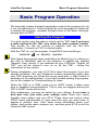
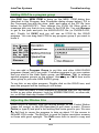
The Network View
The Network View screen is the first screen you see each time you run
the program. You will notice a Status banner at the top of the screen,
and a function key line at the bottom of the screen that should look
something like this:
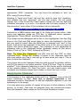
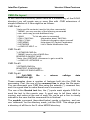
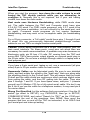
Normal Function Key Line:
1Help 2NetVu 3PrvQSO 4Next 5TxtOps 6Xfer 7Connct 8Path 9Search 10Cmd
Function Key line with [Alt] key depressed:
1Conf 2MHeard 3Term 4DOS 5 6Brag 7Discon 8MailCk 9Next 10Quit
The numbers refer to function keys. "1Help" means push l for
Help. "2Net Vu" means pushing m switches to the Network View
monitor screen. r start contacts and when you hold down the a
key, the bottom line changes showing "7Discon" which means that
a+ris the disconnect or link down key. a+s accesses your
maildrop, and a+u is how to quit the program and return to DOS.
a+ois different, it is the DOS shell, which suspends the program,
saves the current state of buffers, and gives you a DOS prompt. To
leave the DOS shell, type EXITf.
Note: The use of Brackets [ ] is used in the text to indicate a key on the
keyboard. If you see [ESC] in the text, this means the |key. If you see
[Alt-X] this means hold down the a key and then press X. [CtrlF1] means hold down band press the l key.
Type some text: it will go into the cmd/text entry area at the bottom of
the screen. Edit the line with cursor keys, the [INS] key to insert text, the
[DEL] and [Backspace] key to delete text. Go to the beginning and end
of the line of text using the [HOME] and [END] cursor keys. Each
session screen has its own cmd/text entry line.
Sending Text: [Enter] is used to send text. The program requires that
you are on an active session screen, connected to your personal
maildrop, or in a mode that allows text to be sent “unconnected.” If you
do type text, hit [Enter], and the program has nowhere to send the text,
you will see an error message. The chapter on Packet operating goes
into more detail on how to send UI text for example. See page 47.
Editing the Command/Text line: Use the cursor keys to move around
the command entry line. You can use the [Ins] key to toggle the
"insert/overwrite" mode, and the cursor keys to edit the line.
10
InterFlex Systems
Basic Program Operation
Clear the CMD/Text line: Use [Alt-X] to clear the text line, and [Alt-R]
to "retrieve" the last line of text transmitted with [Enter] or sent as a
command with the [F10] key.
Command and Converse "Modes"
In the TNC hardware manuals you will see reference to COMMAND
and CONVERSE modes. In GOLD, you do not enter "Command mode"
or "Converse Mode" because both are available at all times. If you push
[Enter], this means [Send] text, if you push [F10] this means treat the
text as a [command].
[F10] is the “Command” key. The TNC manuals tell you that to view a
TNC parameter setting, type the parameter name from the command
mode. In GOLD, type the parameter and push [F10].
SLOT [F10] (View current setting of SLOT)
The response will appear in a window, and stay on the screen for the
time period set under Screen Settings, the item “Popup window status
display time” which defaults to 5 seconds. To change a TNC setting,
type the parameter name followed by a setting, then [F10].
SLOT 30 [F10]
(Change SLOT to 30)
Parameter Groups: Type DISPLAY [F10] for a menu of parameter
groups. Pick the ID group and push [Enter]. The program reads the
current settings for several identification parameters from the TNC. Use
the cursor to move up and down through the list. You can get help on
the parameter on the same line as the cursor by pushing [F1] twice.
Push [ESC] to return to the program.
Parameters in STARTUP.TNC or SHUTDOWN.TNC override any
temporary settings you make while in the program because these files
are “loaded” when the program is started, and shut down respectively. If
you edit or change a parameter and it doesn’t “stick” between runs, it is
probably being set in either the startup or shutdown tnc file.
Note: a “tnc” file is a plain ASCII text file with one or more parameter
settings. The files have the extension “.tnc” and are found in the tncfiles
subdirectory. Using [F10] with nothing on the CMD/Text line brings up a
list of these “.tnc” files -- Hit [Enter] to load the parameter settings in the
selected file. These files are located in the tncfiles subdirectory. See
page 22 about TNC file layout.
Immediate Commands: Some TNC commands are "immediate" and
may be used to change modes. For multimode TNCs, typing AMTOR
11
InterFlex Systems
Basic Program Operation
[F10] is an immediate command to enter AMTOR Standby mode. In this
case, no popup box appears, the tnc simply does what you tell it to do,
like change modes. This is one of the ways to change modes.
Shell to DOS: Push [Alt-F4] to "Shell" to DOS, which means putting the
program in a state of suspension, storing it to disk, or EMS memory,
and running a copy of COMMAND.COM. You will see a DOS prompt.
Try typing a DIR (directory) command. Change directories if you wish.
Then type EXIT to return to GOLD.
Quit to DOS: use [Alt-F10] to Quit to DOS. This ends the program,
after shutting down the TNC according to the parameters in the file
SHUTDOWN.TNC. This is much different than Shelling to DOS, which
merely suspends the program and gives you a DOS prompt.
Note: [Alt] and [Ctrl] are "shift" keys -- press and hold the key down
before and during the use of the appropriate function key in order to
have effect. Also, there is a difference between [Alt-1] and [Alt-F1].
The first is [Alt] and the number “1” key at the top of the keyboard, and
the second is [Alt] and the [F1] function key.
Program Screens
The program begins with only two screens per port. A Network View
screen and a Previous Sessions screen. If you push [F2] on a dual port
unit (KAM, or dual port AEA unit) you will switch radio ports.
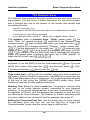
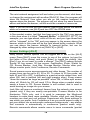
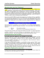
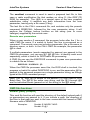
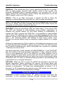
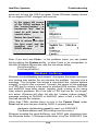
In the example screen that follows, we pushed the [Alt-F8] key to
“connect” to the Personal BBS, or Maildrop. The maildrop prompt is
sent to the screen by the PBBS. The banner shows the mode (in this
case Packet) and the station. It may look slightly different on an AEA
tnc because the maildrop is accessed differently than on a Kantronics
unit, but the basic idea and layout is the same.
The maildrop screen is similar to other connect screens. At the top are
a few lines of monitored activity from the Network View screen. Then
comes the status banner with the mode, callsign, QTH, and TNC status
information. Below that is the session screen that shows text sent to
you and text that you send and receive.
12
InterFlex Systems
Basic Program Operation
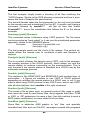
Status
Banner
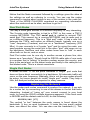
The Status Banner
The status banner is present at all times, except when you are in the
Setup menu area, or in Direct Terminal mode. It contains information
about the status of the session, and of the TNC itself. In the border
surrounding the banner, you will see general information (Date, Time,
Port name if applicable). Rather than look at the TNC front panel to find
out what is going on in your TNC, look at the Status Banner
In Packet mode, if you are connected to another station, you will see
Pending and Tries. Pending means the number of frames in the TNC
itself that are waiting to be sent and acknowledged, or already sent but
not yet acknowledged. Tries is the number of attempts to get an
acknowledgment after the first try. If you mostly see Tries: 0 this means
the link is excellent, and no additional “tries” are required to get
acknowledgments of each packet sent. Typically these numbers are 0,
but on a busy frequency, they will change. Type TRIES [F1] for help on
this tnc parameter.
In non-packet modes, this screen has information about mode, shift,
baud rate, and in AMTOR and Pactor, it displays the various FEC or
ARQ states such as IDLE, Send, Receive, RQ, Phasing, etc.
If I/O buffer memory is shown (not supported on all TNCs), it shows the
remaining size of the tnc memory allocated to serial communications to
and from the TNC. Pending transmitted text uses up this memory. Also,
it is tnc workspace memory, not total tnc memory. As data is sent to the
TNC, you will see this number get smaller, and as data is successfully
transmitted, the number goes up. In DUAL mode operation,
Packet/RTTY for example, two numbers are shown, one for packet, the
other for non-packet modes.
13
InterFlex Systems
Basic Program Operation
Command/Text input line
At the bottom is the screen is the command/text input line. From here,
you type commands and issue them with command enter or [F10] key.
You also type text in this same place, and use the transmit or [Enter]
key to send the text to another station. This is a one-line entry area. If
you want to create a multi-line message before sending it, you can use
the clipboard editor, accessed with the with the [F5] key. See page 54.
Function Key Line
Below the Command line is a listing of function keys and what they do.
The [Alt] and [Ctrl] keys affect what you see. If you depress the [Alt] key,
this list will change to the [Alt]-key definitions. Try it.
Pressing the [Ctrl] key in Packet mode shows all callsigns currently
connected. In non-packet mode, the [Ctrl] key shows different modes. If
you are in BAUDOT (RTTY) and wish to switch to AMTOR, you can do
so using [Ctrl-F4] as indicated when you hold down the [Ctrl] key.
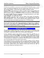
Network View Screen [F2]
The first main screen that appears after the program has completed
initializing is the Network View screen. From this screen, you may
switch to the Previous Sessions screen using the [F3] key (typically
blank when you first startup the program), then back to the Network
View screen with the [F2] key.
Note: On the Dual Port software, [F2] also switches between ports.
Depending on your setting for “monitor” and “mcon” and other monitor
parameters, a copy of all frames meeting the conditions will be put on
the Network View. See your TNC manual for an explanation of these
commands. Type DISPLAY M [F10] for a list of current monitor
command settings.
Mini Network or 2nd Session View
When off the Network View screen, in one of the other screens, a small
portion of the network view may be visible. The number of lines in this
small screen are selected in the setup area, and also depends on the
[Alt-Z] menu setting -- 25, 43 or 50 line mode. You can temporarily
assign text from another session to appear here using the Shift-F4 key.
This is useful for packet-cluster users on dual port TNCs who want
to operate RTTY for example, while keeping an eye on the activities on
the packet cluster. Push [Shift-F4], and pick another session to display.
14
InterFlex Systems
Basic Program Operation
The mini-network assignment will end when you disconnect, shut down,
or change the assignment with another [Shift-F4]. Also, the program will
show the Network View when you are on the session assigned to
appear above the banner. The program will not show the same session
above and below the banner, as this would be a waste of resources.
Note: If you do not see the mini-network view screen above the banner
while on a session, use [Alt-Z] and turn OFF the ZOOM state.
In Non-packet modes, text that has been sent to the TNC may appear
in this area when it is titled "Transmit Buffer." In BAUDOT (RTTY) for
example, you can type ahead, while off the air, and your type ahead text
will be "released" to the TNC and may appear in the screen above the
banner, which in this case will be the type ahead buffer contents. What
you see above the banner defaults to transmit buffer, but can be
changed by other settings such as [Shift-F4] or [Alt-Z].
Screen Settings [Alt-Z]
Many screen related options can be toggled on or off on the [Alt-Z]
menu. Press [Alt-Z], move the cursor to one of the options (or type the
first letter of the choice) and push [Enter] to toggle the setting. Use
[Esc] if you do not want to make a change. The [Alt-Z] options include
Sound, 43 line screen, 50 line screen, Justification, Zoom, Watch for
CQ, Screen Blanker, Junk filter, Process Monitor, Monitor other port,
Merge monitor ports, Auto Conference, Remote Commands.
Sound means morse announcements and other beeps. The number of
screen lines can be set to 43, 50 or 25. To return to 25 line mode, set
both 43 and 50 to OFF. Justification is a packet mode related item, and
when ON, text is justified (left and right margins align). Zoom means
“show the session as large as possible” when ON, or allow split screen
when off. Watch for CQ will send CQ in Morse when a packet station
sends a frame to CQ. Screen blanker is self evident, and is used to
avoid burning an image into your screen.
Junk filter will remove monitored frames from the network view screen
(packet only) if they are mostly non-printable. Process Monitor is for
Kantronics TNCs only, and it is used to rearrange the Monitored
headers to make them more readable. Monitor other port, and Merge
monitors are dual port unit settings. Experiment with these settings to
see which you prefer. Auto Conference is as you would expect a way to
put your station into an automatic conference bridge mode -- any station
that connects is automatically in conference (packet mode only).
Remote commands allows remote users to issue commands (packet
15
InterFlex Systems
Basic Program Operation
mode only) that are defined in the cmdfiles subdirectory. See version 9
new features for more information about remote commands.
Previous Sessions [F3]
Initially this screen is empty. You may also have text from sessions that
took place while the computer was off. On dual port versions, there is a
previous sessions screen for each port.
When a channel (QSO) is disconnected, all text is moved from the
active session screen to the Previous Connects screen. This screen is
essentially a Connect History screen. In non-packet modes, this
screen keeps the results of "previous modes." This means you can
monitor a NAVTEX or FEC station, then switch to Packet, and find the
NAVTEX or FEC text there in your previous sessions screen. This is
most useful for transferring text from one mode to another mode.
All text from the Direct Terminal mode [Alt-F3] is also saved here.
Owners of PK-900 and DSP-2232 units can use [Alt-F3] to get to a
cmd: prompt, type DIR [Enter], get a list of Modems, then return to the
main program with another [Alt-F3].
Active Sessions [F4]
When you establish a connect, or another station connects to you, the
program allocates a new connect screen for all incoming and outgoing
text. All text associated with the QSO is written only to that connect
screen. You may also find the text on the monitor screen, which is normal, as monitored frames may include your own incoming and outgoing
frames. The monitor screen displays frames based on the monitor level
you select. If a frame is also related to a connected channel, and is in
the proper frame number order, the text will be transferred there as well.
You may see frames on Netview that do not appear in the session
screen. If you see frames 1,2 & 4, missing 3, you will not see 4 in a
session screen until your tnc hears frame 3, then 4. Think about this.
[F4] switches only to Active sessions. An Active session is defined as
one with a callsign in the Banner.
On Dual Port units operating a non-packet mode, [F4] will switch to the
non-packet only if there is a callsign in the banner. A non-packet screen
without a callsign is considered an Inactive session, or a monitor-only
screen. To access a non-packet monitor screen, use [F2]. If you want
the non-packet mode to be included in the [F4] switch sessions list, put
a callsign in the banner with [Alt-C].
16
InterFlex Systems
Basic Program Operation
The Session Screen is where you see text that you send and receive.
Pop-up status boxes, menus, and dialog boxes appear here as well.
In Packet mode, you can send text at any time to an active session.
Packet is the only true conversational mode that supports text flow in
either direction at all times.
In the non-packet modes, there is a Sending and Receiving station, and
text flows in one direction at a time. You can type text and it is held in a
“type ahead” area. It is sent (and echoed to the session screen) when it
is your turn to transmit.
Maildrop Access [Alt-F8]
If your TNC has a maildrop, use [Alt-F8] to “connect” to it. Use B)ye
[Enter] when you are finished to free it up for use by other stations.
Macro Strings
When the program sends Alt-n messages, BRG files, and CQ files it
looks for special words, or macros, that start with ? or !. ?CALL
substitutes the callsign in the banner for the string ?CALL. The question
mark (?) causes the string to be inserted, pushing characters to the
right as necessary The exclamation mark (!) overwrites starting at the
position of the !. ?name and !name both write the name of the remote
operator, but ?name inserts and !name overwrites the text.
Type Macro [F1] for help on using macros in the software, and look at
the BRG and CQ files provided for some examples. Macro strings
include CALL, MYCALL, NAME, MYNAME, QTH, MYQTH, FREQ and
contain obvious values during a QSO.
If you are K8TNK connected to N6WIK, The Alt-1 message that reads:
?CALL de ?MYCALL would be sent as N6WIK de K8TNK. If these
macro strings are referred to in CQ or BRG files, the program makes
substitutions accordingly.
One string, QSO is a Qso counter. QSO is also a pseudo-TNC
command, so you can type QSO [F10] to see the current setting (or
setting for each port on a dual port TNC). BANDQSO is a counter for
each band on a dual port TNC. Use either QSO or BANDQSO for your
qso counting. Basically this is intended to be set to 0 at the start of a
contest, and will increment each time it is used, not just on each QSO.
If you determine that a station is unique (not a duplicate) use the Alt-n
message that contains ?QSO to increment the counter, and report the
value to the other station.
17
InterFlex Systems
Basic Program Operation
Logbook and Station
Every contact that is on an active session can be logged easily.
Remember, an active session is one with a callsign in the banner. The
callsign can get there automatically (in Packet, Pactor, Gtor) or
manually (RTTY, Morse) or is entered when you enter a callsign and
push [F7] in all TOR modes, and Packet.
In all broadcast modes, you will enter callsigns manually. Other data
such as Name and QTH can be entered manually, or read from a
callsign database (see the chapter on Version 9 features).
Start/Stop Logging: [Alt-C]
Entering a callsign (whether manually or if it is done automatically)
begins the logging operation for that callsign, recording the date and
time of the session in all modes if enabled in the setup menu area.
Entering a blank callsign ends logging. If the external logging is turned
on in the setup menu area under "logging" a file is created with date,
time, callsign, name, qth, mode, frequency. This file is in a standard
format, quoted and comma delimited, ready to be renamed or copied to
an acceptable name for your particular database or spreadsheet
program.
Canceling a log entry: Depending on the mode and whether a connect
or session has already taken place, you may be able to cancel a log
entry using [Alt-C] and then [Alt-X] to cancel.
Names: [Alt-N]
Use [Alt-N] on an active session to enter the name of operator of
connected station. Then each time you are connected to that station,
the name will appear on the Session screen, next to the call sign. This
is the default behavior, assuming you are allowing the Log all connects
feature under setup/logging. The name may change automatically if the
remote operator has changed his/her name and the auto-recognition
detects the change. The same is true of the QTH, and even callsign.
Connecting to a remote GOLD user through a node may result in
automatically “fixing” the callsign appearing in the banner, changing it
from the node call to the actual remote callsign.
QTH: [Alt-Q]
Add QTH to the station information shown. This may be retrieved from
the other station automatically in Packet mode, or from a callsign
database, or entered manually.
18
InterFlex Systems
Basic Program Operation
QSO Log Edit: [Alt-E]
Edit the on-screen QSO log: Saves last connect information, has editing
window to write information about station, such as address, equipment,
interests, etc. Leave this screen with [F10] as indicated on the QSO log
screen. This is not the same log file or format as the "detailed log"
quoted/command delimited file.
Callsign Lookup: [Alt-I]
Use [Alt-I] and enter a callsign. The QSL "card" for this station will be
shown, indicating the last date and time you worked this station, along
with any comments you may have put there. For those with on-line
callbooks, this function will also access the callbook. See page 75.
Frequency: [Alt-F]
Set the logged frequency for the QSO. This is used in the log file, if
"detailed logging" is enabled. For dual port units, the frequency is
specific to each port. The frequency is "remembered" between runs of
the program. If you change frequency on your radio, enter the new
frequency with [Alt-F]. This also fills the ?FREQ macro string.
Pick Lists -- Navigating...
A “pick list” is a collection of selectable items surrounded by a single or
double line border box. They appear in many places in the program,
from selecting files to picking callsigns out of the Quick Connect list.
Navigating pick lists
We are often asked about mouse support in GOLD software. As it turns
out, even experienced mouse users can find faster methods to select
items from dialog boxes using “hot key” methods. In GOLD, we use the
faster “hot key” approach in all Pick Lists and Menus.
The “pick list” box appears in many areas of the program. This one has
a collection of files. To select Baudot, type the letter “B” and the
selection cursor “jumps” to the first item starting with B. You can use the
cursor keys, but using the “matching letters” method is faster.
If you typed the letter F the cursor would jump to FILEFIND. If you then
typed O the match to FO is FORECAST.TXT. The idea is simple: When
you see a pick list, you can type the first letter, or several letters and the
program will perform a “match” and move the cursor to the first item
that “matches” your letters. This is much faster than using a mouse or
19
InterFlex Systems
Basic Program Operation
the cursor keys to select items. The bottom of this list indicates that the
down arrow, or PgDn key will show more items.
Directory Navigation
The second item of interest is the navigation of directories and drives
when looking for files. The reference to “..\UPDIR” in this example
means you can move up one directory level by hitting [Enter] on this
item. Use [HOME] key to get to the top of the list, then [Enter] to go up
one directory. Doing this several times will let you pick different drive
letters, and eventually you can traverse Down to new sub-directories in
search of the item (if it is a file in the directory tree).
Last, when asked for a file name, type part of the name, using
“wildcards” for the rest, such as:
Filename: *.EXE
This will restrict the file pick list to only those items that have an .EXE
extension, just like DOS wildcards. Use this to limit the search list. You
can type a drive letter and colon (:), e.g. B: for the filename to have
GOLD begin listing files on the B: drive. Then use the first letter
approach to quickly select the file of interest. This is a fast, and easy
way to navigate lists and directories.
Using On-line Help
The on-line help system is filled with TNC parameter information, and
operating mode information and ideas and tnc specific documentation
that is not in this printed manual. KaGOLD has information about
Kantronics hardware and commands, and PkGOLD has AEA related
material. This is a valuable resource.
Accessing Help from DOS with /H
You may want to explore the help system without actually running the
program with your TNC, to learn more about AMTOR or even TNC
wiring or adjustment. To get to the help system, bypassing the normal
TNC initialization, use the "/H" (Help) switch as follows:
PKGOLD/H [Enter] (Access Help from DOS)
Accessing Help from GOLD with [F1]
After starting the program it begins "talking" to the TNC. At this point,
you can access the main help screen index using [F1]. Then use the
cursor keys to find and highlight a topic and hit [Enter].
20
InterFlex Systems
Basic Program Operation
Push the [F1] key for the Help System Index. Use the [Pg] and [arrow]
cursor keys to navigate through the Help System. Use the [ESC] key to
return to the Netview Screen. Pushing the [ESC] key too many times
will produce a small left arrow on the text/command entry line, which is
the display character represented by the [ESC] key. If this happens,
backspace or use [Alt-X] to clear the cmd/text entry line.
Navigating the Help Index
After pushing [F1] for the Help Index, you can then move the selection
bar (cursor) to any topic using several different methods.
•
Using the Up and Down Cursor keys, or PgUp and PgDn to find
an item. This is the “point and shoot” method of navigating the
help index.
•
You can type the first, or first few letters of a topic, and let the
Help Index “Topic Finder” logic match your keystrokes with the
first “hit” it finds matching your selection. It may not appear
obvious that you can type letters on the Help Index screen, but
you can, try it.
Specific Topic or Parameter Help
Suppose you want to change a parameter, PERSIST, but are unsure
what it does. Type PERSIST and push [F1]. When you are finished
reading about PERSIST (and the related items, if any) return to the
main screen with two [ESC]s. With PERSIST still on the command line,
Push [F10] to check the current setting. Then use [Alt-R] to "retrieve"
the last command and append a value or setting, push [F10] again, and
change the setting of that parameter.
Multiple Help Screens
Many help topics are “multi-page” or “multi-screen” and you will want to
read through several screens of information. If you see a [PgUp] or
[PgDn] or in the lower right corner of a Help screen, additional help
pages are available if you press [PgUp] or [PgDn].
Cross Reference Items are words, phrases, or even “Xs” shown in a
different video attribute or color, and possibly surrounded by braces {}.
Move the cursor to one of these items and press the [Enter] key to
access the additional “cross referenced" Help item. This is also referred
to as “Hypertext” -- text that is “keyed” or cross-referenced to other
related text and accessible with a simple keystroke, like [Enter].
21
InterFlex Systems
Basic Program Operation
Backing up using the [Alt-F1] key. Use [ESC] to return to the top Help
Index. A second [ESC] key returns to the main program. Backing up is
not always predictable due to the path taken to arrive at a particular
page in the help system. If things get confusing, use [ESC] to start
again at the Help Index and proceed again.
Help While Editing Parameter Groups
Type DISPLAY [F10] to bring up a list of parameter groups. Select one,
like Monitor Parameters. Hit [Enter] and the program will extract the
current values of Monitor Parameters.
Move the cursor to a line with a parameter on it, hit [F1] TWICE. The
first depression of [F1] provides information about editing or saving
TNC files, but the second depression looks in the help system for
information about the parameter. To exit the help system, use [ESC] to
return to the group of TNC parameters.
There are many pages of useful information in the help system. For
example, look at the Help Index section about Packet Monitoring, and
use [PgDn] to look at ALL of the pages. Check out TNC Installation for
information on setting levels, and calibrating the tones.
TNC Files
A group of TNC settings or commands, stored in a file, and readily
accessed is called a “tnc file.” The group is loaded into the tnc using the
cmd: key, or [F10] key. In GOLD, such files are stored in the TNCFILES
subdirectory (on Version 9) and all have the extension “.tnc” for easy
identification.
The rules for setting up a TNC file are simple:
•
•
•
•
•
Blank lines are ignored, use them to make your files readable
Lines starting with an asterisk (*) are ignored -- use them for
comments
Leading blank characters are ignored -- use them for readability
TNC commands are followed by settings
Text strings all must fit on a single line
Why use TNC files?
On some tncs, you may wish to set several parameters as a group. One
of the most useful TNC files you can create is one that has all of your
identification data in it. For example, WA4EGT has a file called
22
InterFlex Systems
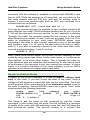
Basic Program Operation
WA4EGT.TNC, and in it are a collection of ID parameters, maildrop
settings, and node settings. Here is an example:
* TNC file for WA4EGT
MYcall WA4EGT
There are several other callsigns you
MYAlias LN0DIG
might want to set, including myautost,
MYNode LN0NOD
mygroup, etc. This is an example of
MYPTcall WA4EGT
what you might do for your own
MYGTcall WA4EGT
tnc file with settings specific to your
MYPBBS WA4EGT-1
station and preferences.
PBBS 95
NUMNODES 4
* Next line shows use of ^M for “new line” -- Use “carat” and the letter “M”
Ntext X-Connects on 14.103 Mhz^MConnect to WA4EGT-1 for Informatoin
NDWild On
WText de wa4egt
Htext CA.USA
This file sets the callsigns for the station, the digipeater, node, pactor
and G-TOR callsign, then sets the PBBS to 97 so that the number of
nodes on the KAM can be set to 4 and still have plenty of i/o memory.
The maildrop parameters are also setup in this file.
To use this file, if the tnc gets reset, or a different tnc is hooked up, all
that is needed is to push [F10], then highlight wa4egt on the list of tnc
files, push [Enter] and all of the parameters are entered as a group.
Another TNC file you might create is for a net or roundtable. If you have
4 stations that you want to quickly connect to, you could create file
called net.tnc (or net1.tnc, net2.tnc etc.) and it might contain a list of
connect requests, as follows:
* net.tnc, used to connect to several stations
c n6wik via wa6hjf
c wb6uut
c ocean\c0ast\nz1m
c wa6hjf
You could quickly connect to all four stations by hitting [F10], typing “N”
and maybe “E” to “point” to NET, then push [Enter] and your station will
begin connecting to all five stations. Notice that the connect requests
can include digipeaters, and in node aliases for working through nodes
using the automatic node hopping feature.
Creating a TNC file
Any ASCII editor can be used to create a TNC file. You can use the [F5]
edit clipboard feature to do it. Enter your commands, then [Alt-X] to
23
InterFlex Systems
Basic Program Operation
save to the clipboard, then Write to disk file, giving the file a name
ending with the tnc extension, such as NET.TNC.
Editing a TNC file
While in GOLD, you can use [Alt-S], then TNC files, to show a list of
existing TNC files to edit. As you make changes, they are verified
against the tnc. Commands in error will show the error. If you put an
asterisk (*) in front of a line, it will be considered a comment line. Push
[F1] once while in the TNC editor for help on inserting and deleting
lines. Push [F1] twice while on a line with a parameter at the beginning
for help on that parameter.
While in the setup area, changes to TNC files are checked to be sure
they will work, but tnc settings don’t get changed until the tnc file is
loaded. This is a TNC file editor, not a tnc editor.
When changes don’t stay changed
Many times you will change a parameter, such as CTEXT, or PERSIST,
and the next time you run the program it seems to be set back to where
it was. This is easily explained.
Each time you run GOLD, the program loads and processes a tnc files
called STARTUP.TNC, If CTEXT is referred to in STARTUP.TNC, then
each time you run the program, CTEXT will be set to the value in this
startup file. And when you shut down GOLD, the SHUTDOWN.TNC file
is processed, and it too may contain parameter settings that override
the ones you may have set.
If you exit GOLD in CMD: mode, a third TNC file is automatically used,
after shutdown.tnc, and this one is exit2cmd.tnc and has parameters
that are most beneficial to cmd: mode.
You can easily check to see if a tnc file does what you want it to do by
simulating the loading of that tnc file. Simply push [F10], and highlight
startup.tnc, or shutdown.tnc, or exit2cmd.tnc, or any other tnc file that
appears in the list, and see if a parameter you are trying to set is altered
by any of the standard tnc files.
Most parameters you change will remain changed, especially if they are
not referred to in any of the standard tnc files. Therefore, don’t clutter
up tnc files with things that don’t change. This is one of the reasons why
the wa4egt.tnc file has all of the identification parameters.
24
InterFlex Systems
Basic Program Operation
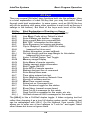
Alt-Keys
There are several [Alt-letter] keys functions built into the software. Here
is a brief explanation of each Alt-Key that you may find useful. Read
through each brief explanation. In some cases, such as [Alt-N] the key
will not do anything until some other condition is met (such as having a
callsign in the banner). But Most of the keys work most of the time.
Alt-Key
Alt-A
Alt-B
Alt-C
Alt-D
Alt-E
Alt-F
Alt-G
Alt-H
Alt-I
Alt-J
Alt-K
Alt-L
Alt-M
Alt-N
Alt-O
Alt-P
Alt-Q
Alt-R
Alt-S
Alt-T
Alt-U
Alt-V
Alt-W
Alt-X
Alt-Y
Alt-Z
Alt-1
Alt-2
Alt-(-)
Brief Explanation of Function or Usage
Display ASCII Character set: Toggle ON/OFF
Line Begin Prefix string: Default is blank
Enter Callsign into banner -- Logging
Enter current Date into command line
Edit "QSL" information for this station
Enter Frequency for logging and display
Flip to “Graphics” screen (ANSI Pic mode)
(reserved for future use)
Station Information, access callbook
Set right Justify and line wrap Margin for this station
(reserved for future use)
Lines: Full/Half Duplex Text Toggle
Memory usage Display
Enter Name of remote operator
Display connect status information
Print Toggle ON/OFF
Enter QTH of remote operator
Retrieve last sent line or command
Enter Setup Menu area
Time string entered into text
Enter [Unproto] mode on Network View
Version of software and tnc
Wipe/Clear current screen
Erase text on Command Line
Save Sessions toggle for this station
Zoom Menu (several screen items)
Send 1st Alt-n message for this mode
Send 2nd Alt-n message for this mode, etc. etc.
Alt-Dash shows all Alt-n messages for this mode
The [Alt-L] is like a Full/Half duplex toggle. It hides outgoing text but
rather than dumping it as a true full duplex system would, outgoing text
can be redisplayed with [Alt-L]. On the Network View screen, [Alt-L]
allows you to enter one or two callsigns to "Look for" and again, hides
other frames but does not ignore them.
25
InterFlex Systems
Basic Program Operation
[Alt-T] and [Alt-D] functions insert the Time and Date based on the
Offset from local time that is entered in the setup area.
[Alt-W] Clears or Wipes the current screen clear of text.
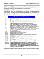
The function keys are summarized on the bottom of the screen with
short names for each function. Holding down the [Alt] key shows the
[Alt-Fn] of each key. The keys change in the non-packet modes, so you
should try them in both packet and non-packet modes.
Function key Summary
F1
F2
F3
F4
F5
F6
F7
F8
F9
F10
Alt-F1
Alt-F2
Alt-F3
Alt-F4
Alt-F5
Alt-F6
Alt-F7
Alt-F8
Alt-F9
Alt-F10
Shift-F4
Help for help index, or help on a parameter or topic
Netview and port change
Previous session, previous mode, change port
Next Session also other port if sessions active there
Text Operations with clipboard and file editor
File send/receive, capture etc. only on active session
Connect to callsign on command line, to call in banner
when in a non-packet mode, or bring up quick connect list
Path shows digipeater paths in ax.25 address fields
Search the current screen for text. Enter some text to look
for, and the program will search backwards from the
current position.
Command enter key
Robot CQ in non-packet modes
Mheard list (packet mode)
Direct Terminal mode, for calibrating TNC, resetting
DOS Shell use EXIT to return from DOS shell
SIAM/OK on AEA units
Brag File transmit, only on an active session
Disconnect in packet, ARQ, and transmitter control
Mail/PBBS check, access maildrop
Repeat Search for the same text as specified in [F9]
Quit Program loads Shutdown.tnc, and exits to DOS.
Temporarily assign an active session to view above the
banner that is usually occupied by a small number of
netview lines. This is useful for packet cluster operators
running a dual port version.
In the next chapter, we will describe several digital operating modes.
26
InterFlex Systems
Digital Operating Modes
Digital Operating Modes
Your TNC can operate in Packet mode and in other digital modes if it is
a multimode device. This chapter offers a framework to better
understand digital modes and how they interrelate.
Morse (CW), Baudot (RTTY), ASCII, and all of the TOR FEC modes
are operated the same way, and are covered in this manual as
Broadcast modes. To operate one of these modes, type the name of
the mode, e.g. RTTY (on the KAM) or BAUDOT (on the PK-type TNC)
and operate according to the instructions in the Broadcasting chapter.
ARQ linked modes, Amtor, Pactor, G-tor, all operate the same way,
different in some ways than Broadcast modes, and are covered in the
ARQ Linked Mode chapter.
Packet mode (HF and VHF) is covered in a chapter by itself, and still
another chapter is devoted to packet nodes and how to use them.
In this chapter you will learn more about the modes themselves.
Consult your TNC manuals for hardware makers idea about how to use
these modes. Then read the chapters in this manual to learn how to run
your tnc in Broadcast, ARQ Linked, and Packet mode.
MORSE (CW)
Samuel F. B. Morse invented and developed the electrically operated
telegraph system in 1832. By the civil war, wires were strung all over
the continent, allowing messages to travel from the east coast to
California. The connection between the “West” and the rest of the
“Union” and the Western Union company is obvious. The transatlantic
cable between the U.S. and France was completed in 1866, and the
rest is history. The International Morse Code as it is called uses
signaling elements of short and long bursts called “dits” and “dashes”
combining to make letters.
The way a computer deals with Morse Code is a bit complex, but for
those interested, here is a brief explanation of how it is done. You can
skip to the next section if you wish:
A dit is a short burst (tone) followed by a short time interval, and a dash
is a longer burst, like three dits hooked together, followed by a short
time interval. The Dits and Dashes are grouped into characters, with the
end of a character being identified by a time interval longer than a dash.
Morse characters can easily be “mapped” into the 8-bit binary character
27
InterFlex Systems
Digital Operating Modes
world of 1s and 0s easily. For example an “A” dit dash can be coded as
11111001, a “B” dash dit dit dit as 11101000 and so forth. The secret to
the coding is to begin each letter as unknown byte, or 11111110. The
decoding of each new incoming morse character begins with this byte
initial byte.
The decoder uses the time of each burst to separate dits from dashes.
Dits are coded as 0s, and dashes as 1s. There are just two issues
remaining: (1) how to add a new bit to the initial byte, and (2) how to
convert the result into a printed character.
To enter a dit or dash, shift the byte left by 1 bit, then set the rightmost
bit to the decoded dit (0) or dash (1) value. When a period of quiet time
comes along, this is the end of the morse character. This scheme will
generate a unique “byte” for every morse code sequence. Now it is a
simple matter to use this byte to access an array of letters and numbers
representing the printed character.
To send a morse character using this scheme, take the printed
character and find the associated morse code byte. Then shift the
morse code bits left until the first 0 bit is found. This is the “start morse
character” bit. Then for the remaining bits, send a short burst for each
0, and a long burst for each 1 until you get to the end of the byte.
WA4EGT designed and hand assembled a morse code (and baudot)
decoder in 1978 using a 6502 computer with 1-K of RAM memory using
this technique.
Note: This scheme shows how each character in the signaling set can
be “mapped” to and from the character set in your computer. This
mapping occurs in morse, baudot code, amtor, and ascii. In Packet,
Pactor, and Gtor, characters sent and received are mapped 1::1 to the
character set in the computer, allowing any of the 256 characters to be
sent without any conversion.
BAUDOT (RTTY)
Next came the 5-bit, fixed “word” length teleprinter using Baudot code
or a similar one called Murray code. Many surplus machines were
available to amateurs after World War II, starting in about 1946, and
have been in service ever since. RTTY is operated at many baud rates,
from 45 to 75, and faster, and at different frequency shifts, from 170 Hz
(narrow) to 425, and 850, with some other “non-standard” shifts used by
certain companies, like AEA in their PK-232 and other TNCs.
28
InterFlex Systems
Digital Operating Modes
Instead of long and short tones being used to differentiate between dits
and dashes, or 1s and 0s, RTTY is based on character frames of a
known time interval, with individual bits being determined at every
interval. If the signaling rate is 50 bits per second, and 1 bit is encoded
in each baud or signaling element, it will take 20 ms (1/50 of a second)
to encode each bit. The RTTY station sends a constant tone, or mark
signal until it is ready to send a 5-bit character. The beginning of each
character is a “start” pulse or start bit, which is either the lack of a mark
tone, or a space tone (on frequency shift keyed stations) for the
duration of one baud time, or 20 ms in this example. The bits are then
sent, a mark or space (or lack of a mark) to represent 1s and 0s. Then,
at the end of the 5-bits, a stop pulse is sent for one or more baud times
(1, 1.5 or 2 stop bits). The next character repeats this process.
Prior to 1953, amateurs had to use ON/OFF keying, sending what
sounded like fast Morse code. The Mark (or tone) condition represented
either idling (between characters) or a 1-bit. The lack of a tone
represented a start pulse, or a 0-bit, and the ending mark tone signaled
the end of the character. On/Off keying, or OOK demodulators worked
somewhat, but after 1953, amateurs could use two tones, or frequency
shift keying (FSK) sending one of two tones continually, improving the
decoding significantly.
The mapping from 5-level codes to 8-bit characters on the IBM PC, for
example, involves keeping track not only of the 5- to 8- bit code
mapping, but the “shift” state. A 5-bit code only has 32 unique
combinations, but with 26 letters, 10 digits, and punctuation, more than
32 combinations are needed. The solution is to use a “shift” and
“unshift” character to signal which mapping is in effect. The terms in
BAUDOT are the LTRS shift and the FIGS shift.
This LTRS and FIGS shift idea causes some difficulty if it is missed,
that is, received in error. Therefore, some stations set a parameter to
“unshift on space” (USOS) to be sure that the LTRS mode is returned
to often. When USOS is ON, the number sequence 1432 4434 5523
1234 for example must be sent with a FIGS shift in front of just the first
number, or in front of every number group.
ASCII
In 1980, the FCC added ASCII, a 7-bit word system, to the list of
permitted modes. Now, amateurs could send upper and lower case
characters over the air without resorting to the FIGS and LTRS shift in
Baudot. Further, 128 unique combinations exist, whereas even with
29
InterFlex Systems
Digital Operating Modes
LTRS and FIGS shift, BAUDOT only has less than 1/2 the character
combinations of ASCII.
Unfortunately, ASCII never really caught on, due in part to the high error
rates that occur at higher baud rates typically associated with ASCII. At
110 baud, errors are commonplace on all but the best signals. ASCII at
lower baud rates should work better, but few amateurs seem to make
much use of this mode. The signaling techniques of baudot/rtty, using
mark and space tones, start bits, stop bits, and individual bit encoding
based on mark or space tones are the same in ASCII.
TOR (AMTOR, PACTOR, GTOR)
AMTOR: Improvements to this original teleprinter system came in the
form of ship to ship and ship to shore systems based on TOR, or
Teletype Over Radio, the commercial version known as SITOR. The
amateur radio version AMTOR was tested in 1982, and added to the
FCC regulations in January 1983 as a permissible operating mode. The
improvement over existing Radio Teletype (RTTY) is evident to anyone
familiar with both modes. AMTOR and the other TOR modes that follow
have two sub-modes, a broadcast mode called FEC (Forward Error
Correction) and a linked mode called ARQ, Automatic Repeat
Request. AMTOR FEC is a broadcast version of AMTOR that sends
every character twice. The receiving station can detect “good”
characters using the scheme described below. NAVTEX is FEC with a
unique message format, that conforms to certain rules. The on-line
Help system has more about NAVTEX, and how to create a NAVTEX
message. You can monitor this mode just like any other FEC
transmission, or you can use NAVTEX as a filter, to receive only certain
kinds of messages or from certain stations.
The error reduction in AMTOR is a great improvement over standard
RTTY. AMTOR operates at a fixed 100 baud signaling rate, using a 7bit word, with only 5 bits containing data like RTTY. The other 2-bits
used at either end of the 5-bit coding are used to force every character
to have 4 mark bits (1s) and 3 space bits (0). Any character not having
this 4 to 3 ratio of 1s to 0s is considered an error. AMTOR uses 4-letter
and 7-letter SELCALS that bear little resemblance to amateur radio
callsigns. In FEC, characters are repeated twice, by the sending station,
and in ARQ, characters are repeated only if the receiver requests it
(Auto Repeat Request).
PACTOR
Pactor is an improved AMTOR. It was developed in Germany and has
been licensed to some companies in the U.S. and reverse engineered
30
InterFlex Systems
Digital Operating Modes
by others. Kantronics has a license and as a result, the KAM adheres
closely to the protocol as defined by the developers. This mode is not
yet formally recognized by the FCC, but it does improve computer to
computer communications, and probably falls under that part of the
rules. Pactor is gaining popularity because of it’s advantages over
AMTOR, which in turn is better than RTTY. Like AMTOR, it has two
sub-modes, FEC and ARQ. Here are some of the advantages:
1.
1.
1.
1.
1.
1.
Pactor uses regular callsigns rather than AMTOR selcals. This
reduces confusion and makes it easier to operate.
Pactor uses an 8-bit code, which means it can send and receive
any IBM graphic character, and send/receive binary files such as
.EXE, ZIP, etc. files without any additional special translations.
This also means that upper and lower case characters are easily
handled.
Pactor operates at two baud rates, 100 and 200, depending on
band conditions. The rate increases when the receiving station is
hearing frames without errors, and slows down when errors
occur.
It uses a memory scheme known as Memory ARQ that sums up
incoming frames that are received in error, and by a technique of
averaging, attempts to create a good frame out of several “bad”
frames. This reduces the number of automatic requests,
improving speed.
Real-time data compression is supported, known as Huffman
coding. This speeds up data throughput.
Polarity is not important, you can operate AFSK Pactor (and Gtor
and Packet too) in either upper or lower sideband, or FSK Pactor
(Gtor and Packet) without concern about polarity. This is different
than AMTOR or RTTY/BAUDOT in which tone polarity is critical
for proper decoding.
G-TOR
This is a new mode developed by Kantronics. It represents another
significant advancement to the array of ARQ modes. Higher throughput
is not its only advantage. G-TOR is strictly a software (ROM) based
enhancement, which means that existing hardware can be used. Unlike
some other modes that claim to be faster than Pactor, users wishing to
run G-TOR do not have to purchase another TNC or computer board.
Gtor was tested on the air during January 1993 between W0XI and
WA4EGT on over 20 separate occasions, under different band
conditions. G-TOR and Pactor were used to send a 9-K file, and in
every case, G-TOR was 3 to 4 times faster than Pactor. In summary:
31
InterFlex Systems
1.
1.
1.
1.
1.
Digital Operating Modes
G-TOR is a ROM software enhancement, no new hardware.
It uses standard shifts, 200 Hz (same as Pactor) and can be
used on radios with AFSK or FSK.
It operates at three baud rates. Presently the rates chosen are
100, 200, and 300 baud.
G-TOR uses an error correction code called Golay code, in both
the data packet and in the response frames which greatly
improves reliability and data recovery.
G-TOR throughput is 3 to 4 times faster than Pactor operating on
the same equipment on the same band at the same time. Tests
comparing Clover and Pactor [CQ Magazine, Feb, 1994, p. 40 ff]
show Clover to be only about 1.6 times faster than Pactor. At first
glance, G-TOR appears to be significantly faster than Clover.
Pactor II and Clover
These modes are not supported by standard TNCs. They use multiple
tones, and therefore TNCs designed for two-tone operation cannot be
retrofitted or adapted to these modes by simply changing a ROM chip.
Further, radios with FSK (i.e. internally calibrated AFSK tone
generators) cannot be used in FSK mode with a multi-tone system, as
the FSK input generates only two tones or frequencies.
There is one interesting feature of Clover that could be adapted to other
modes, and that is automatic RF power adjustments to reduce transmit
power to the lowest possible to maintain the link. This could be done in
existing TNCs and/or radios by altering the AFSK tone levels
dynamically, or the RF power output, based on the number of Repeat
Requests in an ARQ link. With computers at either end of a link, and
the ability to send special frame types with error information, such
control could be done with existing TNCs using a computer controlled
audio stage, or computer control of the transmit RF power through the
AGC input on some radios. Some added external control circuitry would
be needed to use existing TNCs, and the software (like GOLD) would
need to be adapted, but the concept is clearly within reach of existing
TNCs and existing TOR operating modes.
Packet
This mode is based on a bit-oriented frame or packet protocol called
High level Data Link Control (HDLC) or Synchronous Data Link Control
(SDLC) that developed in the 1970’s. The International Standards
Organization (ISO) adopted HDLC in 1979 as a standard. Frames are
of three basic types: Information frames, supervisory control frames,
32
InterFlex Systems
Digital Operating Modes
and Unnumbered frames. SDLC, the IBM version very similar to HDLC,
but restricts the information portion of the frame to be integrals of 8-bits,
which makes it appear to be more of a byte oriented protocol (8-bits per
byte).
As a bit, not character oriented protocol, DLC it is very much oriented
toward bit oriented transmissions, of which serial data (synchronous or
asynchronous) is one. An DLC frame has a flag part (at the start and
end of each packet), an addressing area, a control part that indicates
what the frame is, and a data part if applicable. The frame also includes
a frame check sequence or CRC to determine if the frame is error free.
Packet radio is based on this DLC frame, with changes to the
addressing portion to accommodate callsigns. The protocol, called
AX.25, for “Amateur X.25” is a link-layer system for moving data from
one “node” or address to another, error free.
A frame in AX.25 Packet (and in SDLC) has a control field with two 3-bit
counters to keep track of frame numbers. The 3-bits allow frame
numbers to range from 0 to 7. The largest setting allowed for the tnc
parameter Maxframe (7) is related to these frame numbers.
The protocol identification (PID) section of the frame tells what kind it is.
Normal link layer frames have one PID ($F0). Frames between nodes
may use another PID e.g., $CF. The TNCs have commands to
suppress frames that are not the “Normal” type. AEA uses MPROTO
and Kantronics calls the command PID. Lookup the meaning of these
and notice they are related to the protocol ID of the packet mode
frames.
The address fields in packet allow for a source callsign, destination
callsign, and several intermediate callsigns or “digipeaters” which are
stations that will repeat packets if they recognize their own address as
being the next one to repeat a packet.
Packet radio has the following advantages over other digital modes:
1.
2.
3.
4.
Multiple stations can share the same frequency. This allows for
networking of stations, “chat” nodes, and multi-way QSOs.
Stations are linked in a balanced mode, allowing either station to send
data at any time. There is no need to provide for a link changeover, it
is not necessary.
All data is transported error free due to the protocol.
Any kind of data can be sent, including zip files, word processing files,
GIF images, etc.
33
InterFlex Systems
5.
Digital Operating Modes
The protocol is part of a networking model, which promotes the
networking of nodes, mail forwarding, and complex interconnections
of frequencies, even the mixing of modes (on-the-air stations mixed
with telephone links, satellite links, etc., often referred to as
wormholes).
In the late 1970s, amateur radio packet began with on the air usage. In
the early 1980s more developments and testing of various packet
protocols were done, including HF packet and bulletin boards. By 1984,
the AX.25 protocol version 2 was developed and approved by the
ARRL. Since then, packet has seen growth in numbers, and in
capabilities including network nodes of all sorts, several kinds of BBS
systems (bulletin board systems), even internetwork nodes bridging the
AX.25 packet world with more conventional wire network.
TCP/IP: Other protocols are in use including the Datagram that is used
by TCP/IP stations running NOS or NET. Addressing is contained in
every packet, and KISS mode (Keep It Simple Stupid) is used, and
these are both sources of problems and inefficiency. In addition, the
user interface is weak and complicated, and the need to leave
computers on all the time to maintain station visibility is another
disadvantage. KISS mode creates unnecessary duplicate frames, but
one answer for improved performance is to operate at higher baud
rates. But even at high baud rates, other problems persist.
Most important for owners of multimode TNCs, NOS does not support
other non-packet modes, nor mixed mode operation. And even on
packet, it offers no support for the built-in functions in newer TNCs
capable of larger maildrops (100-K in the case of Kantronics TNCs),
built-in nodes, or station visibility when the computer is turned off.
Digital Modes Summary
In the next few chapters we will show how to operate the software in
each of the three basic modes of broadcasting, ARQ linked, and multistation packet operation.
34
InterFlex Systems
Broadcasting Modes
Broadcasting Modes
All broadcast modes are simple to understand and operate. A station
goes on the air, transmits a message, then unkeys. This can be used
for normal QSOs by broadcasting text, then letting another station
broadcast for a while. Other stations can monitor the broadcasts easily,
as though they were part of the communications. Broadcast modes are
often used for Cqs, nets, and roundtable discussions. For now, type
AMTOR [F10] to put your TNC into AMTOR Standby.
Within this category, different signaling techniques can be used. The
chapter on Digital Modes described Morse, RTTY/Baudot, Ascii, and
FEC modes. Each of these uses a different number of bits to encode
data, and some support upper and lower case characters, others upper
case only. The baud rate is user selected in RTTY/BAUDOT and ASCII,
or fixed in AMTOR FEC, or one of two, as in Pactor FEC. The
Mark/Space “shift” can be narrow or wide, normal or inverted.
But despite the apparent differences, all broadcast modes operate
the same way using GOLD software. Once you learn to run RTTY
you will know how to operate the program in other broadcast modes.
Program Operation
Switch your multimode TNC into any mode that uses or supports
broadcasting. You can type the mode name, then push [F10] to enter
the mode The TOR modes use FEC as a broadcast submode.
Mode Name
Morse Code
Baudot
Ascii
AMTOR Stdby
PACTOR Stdby
Packet
AEA/Pk cmd
MORSE
BAUDOT
ASCII
AMTOR
PACTOR
Packet
KAM cmd
CW
RTTY
ASCII
AMTOR
PACTOR
Packet
Note: Morse mode on the AEA is the same as CW mode on the KAM.
Likewise, Baudot on the AEA is the same as RTTY on the KAM. Use
the appropriate mode name for your particular TNC.
Type the mode name and push [F10]. Mode commands are processed
just like any other tnc command, but the result is a change in modes
35
InterFlex Systems
Broadcasting Modes
rather than a popup confirmation message. Like all tnc commands, you
type the mode name, and push the command key [F10]. The new mode
name appears in the banner.
Note: On Dual Port TNCs, the “non-packet” modes will be available
only on the HF port (KAM) or Port 1 (AEA).
Keying and Unkeying
It is suggested that you turn OFF your radio to test out the broadcast
modes until you are ready to go on the air. With the radio off, you will
still be able to learn how to broadcast, how to unkey, and how to send
text. You can use the LED on the TNC to visually see that the PTT line
is active.
Note: The [ESC] key is used to Key Down, and Key Up in Broadcast
modes. We refer to this as the push to type key.
Push [ESC], you see the <<K>> in the banner, look at the TNC and you
will see the transmit LED lights up. Type some text, and it will echo into
the session screen as it is sent. Push [ESC] again, the <<K>> changes
to a <<U>> for “Unkey” and then the <<U>> is removed, the TNC
unkeys, and you’re off the air again. You may see <<u>> just before
unkeying. Here is what each of the signals or indicators in the banner
means:
<<K>>
<<U>>
<<u>>
-blank-
Keyed down, sending text if any
Unkey command pending, waiting for buffer to empty
Unkey command sent, waiting for TNC to unkey
Unkeyed, ready to accept another [ESC] to key
Sending CQ
CQ in all non-packet modes is done by broadcasting a message even if
you want to have a linked ARQ QSO. From any of the non-packet
modes, push [ESC] to enter the appropriate broadcast mode. Note:
from any ARQ standby mode, use [ESC] to enter the related FEC
mode.
Practice with Radio Off: Turn off your radio. It doesn't need to be on
while you learn how to send a CQ. Type the following on your keyboard,
hitting [Enter] at the end of each line.
CQ CQ CQ CQ DE (use your own callsign)
KKK
36
InterFlex Systems
Broadcasting Modes
Push the [ESC] key, the <<K>> appears, the text will be sent by the
TNC in two directions, over the air, and back to your computer screen
being “echoed as sent” to let you know that the text is going out. Push
the [ESC] key before the text is fully transmitted, you will see the <<U>>
appear, then possibly a <<u>>, and finally the banner is cleared of the
transmit indicator, and the PTT LED indicator goes out.
Resending using Copy/Paste buffer: If you typed your CQ message
manually, and want to resend it, you can use the Clipboard to select the
text, and then copy it again and again to the current session. Text in the
outgoing buffer will be sent when you press [ESC] to key down the
transmitter. When the text begins echoing back, hit [ESC] again to
setup the <<U>> unkey flag, to unkey when the buffer is empty.
Sending a CQ Brag file: Using the brag file approach is easier. Press
[Alt-F6] and the program will produce a list of files ending in .BRG
extension. You may see file names such as CQAMTOR or CQBAUDOT
for example. Note: A BRG file is just a text file with a .BRG extension.
The BRG file contents are copied to the outgoing text buffer.Push [ESC]
to start sending, and push [ESC] again to queue up an unkey.
Robot (Automatic) CQs
The easiest way to send CQ is to use the automatic Robot CQ system
built into the program. It sends text in files that have a .CQ extension.
You can create a CQ file starting with one of the .BRG files that you
may have. For example:
COPY CQFEC.BRG CQFEC.CQ
This makes another file, true enough, but the two serve different
purposes, and can contain different text if desired.
To begin a Robot CQ from a RTTY (Baudot) get the TNC into a nonpacket mode, then use [Alt-F1] and follow the prompts. Select a file to
send, and let the system do everything automatically. The first time you
try this, it is a good idea to turn off your transmitter and watch what is
going to happen. Let it go through a couple of calls. Then use [ESC] to
cancel the automatic CQ.
The Robot CQ defaults are 10 seconds between CQs, and an unlimited
number of CQs. This may change, so do not be surprised if the values
differ when you actually run the program. You can set it to 5 CQs or
some other value.
37
InterFlex Systems
Broadcasting Modes
Ending a Robot CQ: [ESC]
CQ mode can be canceled using the [ESC] key a single time. It cancels
the CQ, but any text in the transmit buffer will be sent, then the station
will unkey, and the CQ mode will be finished. You can use [Alt-F7] and
“Zap the transmit buffer” An automatic FEC CQ is ended with another
station "Links" to your station in ARQ mode. Entering a callsign with
[Alt-C] also ends the CQ Mode, as does changing modes (from AMTOR
to RTTY/BAUDOT for example).
Unkeying Immediately: If it is an emergency, and you want to
terminate the CQ immediately, or if transmitting, you want to unkey
immediately, change modes using the [Alt-Fn] method. Switch back to
Packet with [Control-F1] or to another HF mode with [Ctrl-Fn], e.g. from
[Ctrl-F2] to switch to RTTY.
When someone answers your CQ
Suppose your CQ is answered by AZ6ZZ. Use [Alt-C] to enter the
callsign (not necessary if in Pactor or G-TOR). Then immediately hit
[Alt-1] the first alt-n message, which reads "?CALL de ?MYCALL" to
create an identification exchange line, and hit [Enter]. While AZ6ZZ's
text is being received, you may begin typing your response. As you type
each line, it will be placed into the outgoing buffer area, and shown in
the space above the banner (if the transmit buffer is being shown). If
you were connected in an ARQ link, see the next chapter. If you were
answered by another broadcast (FEC, RTTY, etc) use the [ESC] to key
the transmitter when your turn arrives. Any outgoing pending text is
echoed to the session screen as it is sent and you can add more text.
Turn it back to the other station by pushing [ESC], and your station will
go into receive mode when the buffer is empty..
Broadcast Summary
Broadcast modes, Morse (CW), RTTY, ASCII, and FEC are all easy to
operate. The [ESC] keys and unkeys the transmitter PTT line, and text
you type is transmitted, or queued up in an outgoing transmit buffer.
The TOR modes (Amtor, Pactor, Gtor) go into an FEC mode when you
push [ESC] from one of the standby modes and FEC is also used to
send Cqs prior to entering a linked ARQ mode. The next chapter goes
into ARQ linked modes.
38
InterFlex Systems
ARQ Linked Modes
ARQ Linked Modes
These are two-station only modes. This includes AMTOR, Pactor and
G-TOR. While each mode has technical differences, they are all
operated in virtually the same way. One station (the master station)
issues a link request to another station (the slave station), after which
the master is the sending station. Data is sent, and the receiving station
acknowledges or requests a repeat of the last frame. This is ARQ which
means “automatic repeat request.” Type AMTOR [F10] to enter Amtor
Standby if your TNC is on and the program is running.
The Information Sending Station (ISS) sends data to the Information
Receiving Station (IRS). Then the sending station issues a changeover,
giving up the up the sending status, and becoming the receiving station.
In many ways this is like the broadcast modes, with only one station at
a time transmitting, but unlike broadcast modes, it is a two station
mode, with continual data and acknowledgments flowing back and
forth. For this reason, ARQ linked modes are very good at holding
frequencies because any interfering station is bound to hear one (or
both) of the linked stations at frequent intervals.
ARQ links are typically started like any other QSO, beginning with a CQ
message sent using a broadcast mode [see page 35]. In AMTOR and
GTOR it is AMTOR FEC, in Pactor, it is PACTOR FEC. The CQ
message will indicate whether the answering station should come back
in ARQ or FEC, and in which mode (in the case of GTOR or AMTOR).
ARQ Frames
Data in ARQ modes is transmitted in bursts, or frames. The frame is
received, analyzed for errors, and answered with a short burst of data
that is either an ACK (acknowledgment) frame or a request for a repeat
of the data. The objective in ARQ modes is to transfer data without
errors. Each ARQ mode has a different technique for assuring error
free communication, as described in the chapter on Digital Modes, but
the user need not be concerned about the details, only the fact that
error free communications is an objective of ARQ.
The ARQ link is time critical, and tightly coupled with each station going
on the air as the sending or receiving station at precise time intervals. In
AMTOR ARQ, the interval is very short, in Pactor, the intervals are
longer, and in G-TOR the interval is even longer.
39
InterFlex Systems
ARQ Linked Modes
Monitoring ARQ QSOs
ARQ can be monitored using the Listen mode of AMTOR (ALIST or
LAMTOR) and Pactor (PTLIST). At this time, there is no support for
monitoring GTOR ARQ. In each of the listen modes, you will print ARQ
data packets (the longer of the two type packets in ARQ) but not ACK
packets (the short ones). Note: when in any non-packet mode, use the
[Ctrl-F6] for Amtor Listen, or [Ctrl-F9] for Pactor Listen. On the AEA
tncs, the ARXTOR command will, when on, automatically switch among
various modes (see AEA documentation) and PkGOLD will track the
TNC mode changes without any problem.
The Standby modes will usually print any FEC transmissions if the
TNCs are operating with default settings. SRXALL on the AEA is one
such setting that should be left in the default state, which is ON. If you
are operating one of the two LISTEN modes, GOLD will flip your TNC to
standby if a call comes in to your station.
ARQ Links with GOLD: [F7]
All ARQ modes operate the same way in GOLD software: you establish
and break links in the same way, and you turn over the link in the same
way. Once you know how to operate one ARQ mode, you will know how
to operate the other ARQ modes.
From the standby mode of Pactor, Amtor, Gtor, you can type in the
remote station’s linking callsign and push [F7]. In AMTOR, this callsign
is typically the station’s 4-letter or 7-letter SELCAL. In Pactor and Gtor,
it is typically just the station’s callsign. To cancel an ARQ request in
progress, Use [Alt-F7] followed by [Enter]. There is more about the
process of breaking an ARQ link later in this chapter.
If you type the remote station’s callsign, and push [F7], an ARQ link will
be started with the remote station. In Pactor and Gtor, using the callsign
is expected, in AMTOR, a SELCAL is expected. GOLD will
automatically create a 4-letter or 7-letter selcal from a callsign. Simply
type WA4EGT [F7] and in AMTOR ARQ, the program will create the
proper 4-letter SELCAL and begin an ARQ link with WEGT, the
expected SELCAL.
Quick connects are also supported. Pushing [F7] with no callsign or
selcal will produce a list of stations in your Quick Connects list. When
you entered quick connects, one of the parameters was the SELCAL,
and if in AMTOR, GOLD will use this selcal. Otherwise, GOLD will begin
an ARQ session with the callsign shown in the quick connects path.
40
InterFlex Systems
ARQ Linked Modes
Note: Version 9 adds a new capability: Put a callsign in the banner
using [Alt-C]. When you push [F7] with a blank text/cmd entry line,
GOLD will assume you wish to connect to the station shown in the
banner and it will begin an ARQ link with that station. This is a fast way
to setup your station for a connect. Put the callsign in the banner with
[Alt-C] then when you are ready, just push [F7] to connect.
Changeover in ARQ: [ESC] key
After the sending station finishes a message or wants a response from
the receiving station, the sending station issues a changeover. In
AMTOR, the changeover is strictly done with characters appearing in
the text. In Pactor and Gtor, the link is changed with a TNC command
to request the TNC to send a changeover command to the receiving
station.
Note: Just like Broadcast modes use [ESC] to unkey after the text is
sent (buffer is empty) ARQ uses the [ESC] key to changeover the link
after the data is sent. In both modes, if you are sending data, use the
[ESC] key to let the other station send data.
GOLD uses the [ESC] key in all TOR modes to cause a changeover to
occur when the buffer empties. You can hit [ESC] before the outgoing
text is finished sending. When the buffer empties, the changeover
occurs. In AMTOR, GOLD puts the required “+?” in the text stream. In
Pactor and Gtor, GOLD adds an optional changeover indicator string,
and then issues a changeover TNC command.
Changeover String: The optional changeover string from defaults to
“<+?>“ but you can change it to “GA>“ or whatever suits your
preference. The default setting of “<+?>“ is intended to look like the
Amtor “+?” changeover string, but with the angle brackets around it to
indicate that it is not the same as AMTOR. In Pactor and Gtor, a
changeover string is not used to cause the changeover, it is simply
used as an indicator to the sender and receiving station. You can
change the string used in Pactor and Gtor in the Setup menu.
To summarize: The [ESC] is used when you are finished sending text.
In a broadcast mode, use [ESC] when you are finished sending and
want to unkey, and in ARQ, use the [ESC] when you are finished
sending and want to let the other station become the sending station. In
both cases, [ESC] is used to let the other station send text.
41
InterFlex Systems
ARQ Linked Modes
Forcing a Changeover: [Alt-F7]
If your station is the receiving station, you must either wait until the
remote station turns over the link, or you can force a changeover from
the receiving mode. This is done with the [Alt-F7] key, which brings up
the “transmit control” menu. Choose Force Changeover. This is
considered poor form when operating TOR, but it may be necessary in
some cases.
Breaking an ARQ Link: [Alt-F7]
The sending station breaks an ARQ link. If you are the sending station,
push [Alt-F7] and pick one of the disconnect methods from the list. A
very abrupt and fast way to drop a link is to change modes. You can
use [Control-F2] to switch to RTTY/BAUDOT, or even faster, turn off
your TNC. The preferred method is to use [Alt-F7] and use the method
defaulted to by the program.
The normal way to bring a link down is to be the sending station, use
[Alt-F7], hit [Enter] and let GOLD send the file named ARQ.SK, which
has the message about dropping the link. You can modify the text in the
ARQ.SK file with any ASCII editor to customize your “Link down”
message.
ARQ Summary
The ARQ modes, AMTOR, Pactor, and G-TOR all operate the same
way. Use the TNC manual for parameters that apply to each mode, and
the on-line help system for more details. Basically, you will use FEC to
broadcast a CQ using one of the methods described in the previous
chapter on Broadcast modes. Pactor and Gtor use normal callsigns for
linking, AMTOR uses a SELCAL, typically just the 4-letter version, but
this is generated automatically when you type a callsign and push [F7].
You can read about the 4 vs. 7-letter variety in your TNC manual.
You link with [F7], do changeovers with [ESC] if you are the sending
station, or grab the link with the appropriate [Alt-F7] menu choice. You
end the ARQ if you are the sending station with [Alt-F7]. There isn’t
much mystery, and just a few simple keystrokes to run ARQ modes.
In the next chapter, we will cover Packet radio.
42
InterFlex Systems
Packet Operating
Packet Operating
Most users will run packet before running other modes even though the
other modes are often easier to use. But hopefully, you read the other
chapters even if packet is the only mode you plan to use.
On the other hand, many of the features available in the Packet Mode
are available in the other modes (if your TNC supports multiple modes)
so you should read this chapter even if you don't plan to run packet
mode. We designed the software to make it easy to operate different
modes without having to learn different keystrokes. As a result, ARQ
modes work very much like packet mode, as you will see.
Packet mode is unique because it supports multiple users on the same
frequency, promotes multiple connects or “sessions” and it allows the
use of intermediate stations to help achieve “connectivity” to other
stations. Many software programs do not take advantage of these
unique capabilities of packet mode, but GOLD fully supports multiple
sessions, background file transfers, conference mode, quick connects
through nodes and digipeaters, and more.
Of all the digital modes, packet is the most versatile, even though it is
often misunderstood, especially on HF frequencies. Multiple sessions,
and connectivity means many stations compete for time on the same
frequency. If packet were operated in a manner similar to AMTOR or
Pactor, with only two linked stations at a time, sending short frames,
one at a time, with lower baud rates, it could prove to be a formidable
competitor for “best HF mode.” Unfortunately, it is not presently
operated as a two-station linked mode on HF, but you may be one of
the users who will experiment with this approach. More on this topic
later. Meanwhile, let’s go through more on packet operation, picking up
where we left off in the previous chapters.
Responsible Packet Operation
The advantages of packet radio are also the source of problems when
users do not understand how a shared frequency should operate.
Impatient users often set parameters that dominate a frequency,
causing other users to respond with equally or more aggressive station
and tnc parameters, with the eventual result that nobody gets any data
through and the frequency is trashed.
43
InterFlex Systems
Packet Operating
Running high power, putting digipeaters or nodes at high elevations,
and Dxing on VHF packet take what should be a cellular network
concept and try to make it into a wide area coverage system with a
single or few nodes. Packet should be though of more like mobile
telephones working through relatively short range cell sites,
interconnected on high capacity “backbones” which is what makes
cellular telephones work.
You will hear more enlightened packet users talking about cellular
concept, backbones, connectivity of nodes, wormholes (nodes
connected by satellite or telephone links), user frequencies, etc., all in
an effort to improve the Local Area network concept of packet.
You will quickly see other users doing what they think will work, with
beam antennas, power amplifiers, and “hot” tnc parameters. Watch the
network view screen, and be sure to watch your own transmissions as
well, to assess the impact your station is having on the other users of
the frequency. This is responsible packet operation.
Monitoring Parameters
MXMIT: This command allows monitoring transmitted data. You can
watch a packet session get started, see how data is sent and
acknowledged, and how the session is disconnected. Not all TNCs
support the MXMIT command, but if yours does, set MXMIT ON. With
MXMIT on, you should have a fairly complete picture of what your
station can hear, including your own packets.
MONITOR is a parameter on both AEA and Kantronics TNCs. Type the
parameter name and push [F1] for help on how your tnc uses this
command. On the AEA tncs, MONITOR 6 is the highest degree of
monitoring. On Kantronics, MONITOR ON is the master switch, and
other monitor settings need to be enabled as well. The Help system has
a lot of information about getting the most out of the monitor settings. A
related command is MCON, or Monitor While Connected, and it too
should be ON during normal program operation.
PASSALL is another setting that will let your station “print” or show
frames that do not have good “frame check” values, that is, were
received in error. Normally, PASSALL should be OFF, but if you are
hearing weak stations, or want to print more things, set PASSALL ON.
Note, this defeates the MHEARD list capabilities, while it is ON.
PID (Kantronics) or MPROTO (AEA) is a command that when ON, will
allow your station to monitor frames that are not ordinary AX.25 frames.
This will include Net/Rom frames, TCP/IP frames, and others. Turn it
44
InterFlex Systems
Packet Operating
ON if you want to see even more packet activity that is on the
frequency.
Setting up Maildrop
AEA users turn on the maildrop with the MAIL ON command.
Kantronics TNCs enable the maildrop by allocating memory to it using
the PBBS [n] [F10] command. The PBBS defaults to 5-K or 100-K
depending on your TNC and memory. Set your maildrop callsign to your
call with an "SSID" of "-1" which means if your call is N6WIK, you would
use N6WIK-1.
AEA:
MYMAIL
N6WIK-1
[F10]
Kantronics: MYPBBS N6WIK-1 [F10]
You can name your maildrop some 6 character (or less) name, such as
WIKBBS if you wish, but this is atypical.
Next, decide if you will allow 3rd party traffic. That is, can some other
user leave a message for some 3rd party. If you are N6WIK, will you
allow WA4EGT to leave a message for WB6UUT on your maildrop? If
so, make the following changes:
AEA:
3RDPARTY ON
[F10]
Kantronics: PBPERSON OFF
[F10]
Access the maildrop or PBBS using the [Alt-F8] key. Do it now, and
then create a Bulletin to All, as follows:
SB ALL@ALLUS [Enter]
This "Send Bulletin" to "ALL@ALLUS" means you want to send your
message to everyone in the US. Not a good idea at this point, but will
useful as a test. The maildrop will ask you for a subject, then the
message text itself followed by /EX or a control-Z, as follows:
Maildrop: L)ist, R)ead, S)end, SB)ltn, ST)fc, E)dit, K)ill, B)ye
SB all@allus
Subject:
Testing
Enter Text, Ctrl-Z to end:
My First Maildrop Message to everyone, everywhere
/ex
Message 1 saved
45
InterFlex Systems
Packet Operating
Your maildrop may not look exactly like this, but the concept is the
same. The maildrop commands R)ead, L)ist etc. are single letter
commands. Some need an "argument" or value, such as Read. To list
the messages, use L for L)ist. Read the message you created. If it is
message number 1 you would issue the following command to the
maildrop:
R 1 [Enter] (read message 1)
Last, remove or delete the message using the K)ill command, for
example, issue the command:
K 1 [Enter] (kill or delete message 1)
Notice that the commands to the maildrop are sent to the maildrop
using [Enter] and not [F10]. The reason should be clear, these are
commands or instructions to the maildrop, not TNC commands.
Mail Forwarding
The AEA tnc maildrop will reverse-forward mail only if connected to by a
station with the callsign specified by the HOMEBBS command. The
Kantronics maildrops will reverse-forward to any other BBS station that
responds with BBS type commands. By reverse-forward we mean send
mail to a BBS when it requests it.
You can arrange with your local BBS SYSOP to do "Auto forwarding" to
and from your maildrop. AEA users will then assign the HOMEBBS
parameter to the callsign (no ssids, just the callsign) of the local BBS.
Kantronics users don’t have to do anything special to accept or reverse
forward mail.
Newer Kantronics units also support true mail forwarding, that is, they
will connect to a remote BBS, do mail forwarding, and disconnect, all
automatically. This is handled by the PBFOrward command. Read more
about PBFO in your Kantronics manual.
Note: PBFO on Kantronics units will only work if HTEXT is set with
some heirarchical address. Refer to the Kantronics manual.
To log off your own maildrop type the letter "B" [Enter]. Read more
about your maildrop in the TNC manual and the help system.
AEA:
MYMAIL
[F1]
for
help
Kantronics: MYPBBS [F1] for help
46
InterFlex Systems
Packet Operating
Calling CQ in Packet [Alt-U]
We briefly touched on this subject earlier. You issue CQ messages
from the Network View screen while in Unproto CQ mode. Normally,
you cannot type messages from Network View as it is a "monitor"
screen. This avoids transmitting frames by mistake. But to call CQ in
packet requires sending out unnumbered information [UI] frames. From
the Network View screen, switch to the "Unproto CQ" mode using
[Alt-U]. You should see "Unproto (CQ)" in the banner. You may now just
hit [Enter] to send a [UI] frame. The "address" of the frame is set with
the UNPROTO command. You can specify that your [UI] frame be
digipeated, and addressed to TEST or GROUP for example. Try setting
the following:
UNPROTO CQ VIA LNDIGI [F10]
Now, any text you send will be addressed to "CQ" as well as digipeating
your Unproto signal via the LNDIGI digipeater. If you don't have a
digipeater named LNDIGI, the frame will simply not be digipeated, but
no harm is done if it isn't digipeated.
Set your UNPROTO back to just CQ for now.
UNPROTO CQ [F10]
You can add text to your CQ/Unproto frame by typing it before hitting
[Enter]. It will go out as a [UI], using the UNPROTO path.
Note: Leaving the Network View screen turns off Unproto CQ mode. If
you return with [F2], reissue the [Alt-U] command to "turn on" the
Unproto feature again from the Network View screen.
Packet Beacons
Beacons are transmissions made automatically every few minutes (or
hopefully less often) to announce your station. BTEXT is the text sent,
and BEACON sets the time interval. The tnc manuals, and the help
system go into more detail. Generally speaking, beacons are
unnecessary, and frequent beacons are annoying to other users. Keep
them to a minimum, or better, only use them in rare instances or for
special purposes.
Mheard: [Alt-F2]
The [F2] Key gives you the Network View screen, and the [Alt-F2] key
gives you a list of stations “heard” on the network. On Dual port units, a
47
InterFlex Systems
Packet Operating
separate Mheard list is displayed for each port. Switch to the port and
use [Alt-F2] for that port.
Connecting to a Station [F7]
From any screen, type a callsign of a station you know to be in the area,
then press [F7], the connect key. The program will pick an available
TNC channel, and request a connect. The banner may show Connect in
Progress, and if it takes more than one attempt, you will see the
number of "tries" as it establishes a connect. When the link is
established, the status will change to Connected and then begin
displaying other tnc status remarks in the banner.
A message may pop-up and the program will send the station callsign in
Morse code through the PC speaker (or sound board) unless you
disabled “sound” on the [Alt-Z] menu.
If you don't know any stations to connect with keep reading, and let your
TNC listen for you. Soon you will see some callsigns appear. Callsigns
marked with asterisks (*) next to them are stations you can hear
directly. You may see stations with "SSIDs" which are the numbers after
the callsign, like WA4EGT-15. These may be nodes, not the actual
station itself. Nodes will "assume" the callsign of a user of the node in
order to establish connects on behalf of the user. Thus you may not be
able to connect to every callsign you see with an asterisk (*) -- only
those that are "real" stations, and not "assumed callsigns" of a local
node.
Connected to a Gold User ?
Once connected, you may send a greeting. If you see the word "GOLD
user" appear in the lower right corner of the banner just wait... the
remote operator's Name and QTH should arrive at your station
momentarily. Otherwise, you can manually enter the remote operator
name, using [Alt-N], and QTH using [Alt-Q]. Notice, if you connect to a
user of our software the Name, QTH and logbook entry will be handled
automatically. Also, if you have one of the callsign databases supported
by GOLD, the data will appear automatically. See page 75 for more
about callbook support.
Sending Text in a Session
As you type your QSO text, don't worry about hitting the [Enter] key, the
program automatically does "word wrap" just like a word processor,
splitting lines between words when appropriate. If JUSTIFICATION is on
in the Zoom menu [Alt-Z], the program will also insert spaces to justify
48
InterFlex Systems
Packet Operating
your outgoing text (Packet mode only). Like using a word processor
program, you only hit the [Enter] key at the end of a thought or
paragraph, or to force immediate transmission of a partial sentence.
You can set the right margin with [Alt-J] up to column 80. The
default setting is "0" which uses column 72 for VHF and HF packet
mode, and 68 in all non-packet modes.
To see text that has scrolled off the visible portion of a screen, use the
[Up] arrow cursor key, or [PgUp]. Return to the bottom of the window
using [Dn] or [PgDn] or just switch to another session and back again.
Also, try [Ctrl-PgUp] go get to the beginning of the text, and [Ctrl-PgDn]
to get to the end of the text. Check the Network Screen with [F2] and
return to the session screen with [F4].
Disconnecting [Alt-F7]
When you are through chatting, press [Alt-F7] and select Normal
disconnect. A «D» is displayed after the link state to signify that this
channel will be disconnected after all outstanding text is sent. When the
channel is disconnected, the program will send SK in Morse through the
computer speaker. You may then press [F2] to go back to monitoring,
or press [F3] to review the QSO on the Previous Sessions screen.
Multiple Connects [F7]
Connect to as many stations as you wish, just as you did with the single
station above. Type a callsign, then hit [F7] for each connect. Switching
among session is easy using [F4]. This is one of the unique advantages
of Packet mode -- the ability to handle multiple sessions on the same
frequency. Learn to make connects when you feel like it, and do not
think you must disconnect with one station before starting a QSO with
another.
Suppose you are W1XYZ. N6QRZ sees the conversation on his screen
and decides to connect to you. When he does, a box pops-up on your
screen, telling you that N6QRZ has connected, and you will hear
N6QRZ in Morse from the PC speaker (if the morse speed is not 0, set
in the SETUP area of the program).
You can switch between sessions with the [F4] key. If you see
F4:N6QRZ in the banner outline, when you press the [F4] key, the
ongoing QSO is saved, and the display jumps to the "Next" session.
Pressing [F4] will jump to the next session, or to the session with the
most recent incoming text. You do not need to know or worry about
"streams" or session numbers. Just how to move from session to
session with the [F4] key.
49
InterFlex Systems
Packet Operating
Disconnecting the right session
When you finish a QSO, get to the appropriate session screen with [F4],
then press [Alt-F7], select NORMAL disconnect, and the displayed
channel will be disconnected after a few seconds, without affecting any
other session. If you begin to disconnect and change your mind, hit
[Alt-F7] again before the countdown gets to 0, and select "Cancel
Disconnect."
Note: Pressing the [Ctrl] key by itself will display a list of callsigns at the
bottom of the screen. As shown before, you can use [F4] to move from
session to session, or let the program jump immediately to the next
session with incoming text, or as a third alternative, you can hold down
the control key and pressing the [Fn] key associated with the callsign.
Connecting on another Port
On Dual Port versions of GOLD, [F2] switches ports. If you want to
connect on the other port, push [F2] to get to the right Network View
screen, then make your connect on that port. The [F7] connect key
always attempts a connect on the "current" band (shown on the
banner).
Quick Connects [F7]
The program supports both manual and automatic Quick Connects,
which is simply a shorthand notation that tells the program how to get
from your station to some remote station once. The notation is a
connect "Path" listing nodes and digipeaters. If you setup the path in
your quick connects list, then any time you wish to connect to the
remote station, you simply request a connect from the list.
Node Hopping: The program knows how to work through NET/ROM,
KaNODE, Texnet, MSYS and other nodes that behave like NET/ROM
nodes. It connects, waits for responses, then issues the next connect,
just like you would manually.
If you manually connect to NODE1 VIA DIGI1, then NOD2, NOD3 and
finally connect to W1ABC, you can specify this path as follows:
NODE1 VIA DIGI1\NOD2\NOD3\W1ABC [F7]
The backslash (\) is the node path separator (just like DOS) or you can
use the vertical “or bar” (|) above the backslash (shift-backslash) on
most keyboards. The help system has more information on quick
connect paths.
50
InterFlex Systems
Packet Operating
Adding a Quick Connect Path
To add a quick connect path, use [Alt-S] for setup, then "Quick
Connects" then "Add Path." There are two important entries in a quick
connect, the remote station's identifier, such as the operator's name (or
tactical callsign) on the first line, and the actual route or "Path" to the
station on the second line. The route or path might be just a callsign, or
a "Callsign via Callsign" or a node name followed by the "or bar" or
"pipe" symbol (the vertical bar over the backslash key).
The program will insert an Amtor ARQ Selcal for you, either a 4-letter
or 7-letter SELCAL depending on the setup option you chose. It defaults
to 4-letters. You can override the selection by typing any SELCAL, and
when running AMTOR, the quick-connect list will begin an ARQ session
with the selcal shown.
Tell the program to save the entry, then back out of the setup area
using multiple [ESC] characters. Don't hit the [ESC] more than
necessary, or the program will insert an [ESC] character into the
command line. If it does, clear the command line with [Alt-X] or
backspace over the extra characters.
Using Quick Connects
With Quick Connects in the system, you simply hit the connect key [F7]
with no callsign on the command entry line. You will be presented with a
"Pick list" of names and callsigns. Move the cursor to the one you want,
hit [Enter] and let the program do the work of connecting. This is
especially useful if the target station is several nodes away, through a
complex route or path. The program will do the waiting, and issue the
connect requests for each subsequent node automatically.
Local LF: Ctrl-Enter
A Local Line Feed can be invoked with the [Control-Enter] key
combination. This is useful when you see text being “split” strangely on
the screen. One of the powerful features of this software is that it
attempts to keep all incoming lines together by holding local line feeds
until the remote sends a Line Feed. If the remote station has his
PACLEN set to less than the line length, the software will do what it can
to re-attach the split lines onto a single readable line.
Unfortunately, some operators and BBS systems send lines without any
End of Line (EOL) character, which may result in a “hanging” line at the
bottom of your screen. Your text will seem to be going in the screen
above the incoming line. This is caused by the remote not sending an
51
InterFlex Systems
Packet Operating
appropriate “EOL” character. You can force the software to “see” an
EOL using [Control-Enter].
Sending a “local Line Feed” will end the “wait for new line” condition,
and release the line “segment” into the text screen. Do not make
regular use of the Local Line Feed option unless you find the split line
condition annoying, or in error. You should ask the other station to “Hit
the return key” more often if the condition occurs frequently.
The Clipboard: Copying/Pasting text
Connect to a BBS system and type H for Help and press return. After
some text appears, press the [F5] key. A clipboard menu appears.
Highlight the "Select Block" and then press [Enter].
The screen is now displayed with a line of text highlighted. Use the [Pg]
keys or the [Up] and [Dn] arrow keys to move the highlight to the first
line you want to select then the [End] key to indicate one "end" of the
block, then move the highlight to the other end of the text you want to
select, and press [End] key again. The selection is now appended to
whatever was in the clipboard buffer (probably empty at this point).
Select Print or File or "Quit" followed by [Enter].
Note: To Clear the Clipboard use [F5] and find the ZAP or clear
clipboard entry. Notice the number of bytes in the clipboard may be
non-zero before you Zap it, and will go to zero when you zap it. This is
how to clear the clipboard.
If you have text in the clipboard that you wish to send to another station,
use [F4] to switch to an active session. Push [F5] then "Copy to current
session." Your clipboard selection is sent to the screen and is delivered
to the remote station. On Dual Port units, you can switch ports, and
cut/paste text between bands and modes, or send the text to a file.
Emptying the Clipboard
Text remains in the clipboard buffer until it is "Zapped" (one of the F5
menu selections is Zap). New text is always appended to the
clipboard contents. Remember to zap the clipboard regularly if you are
expecting it to be empty.
You may send any number of copies of the text to other stations, to the
printer, or to disk. Text may be selected from any connected screen,
from the Network View screen or the Previous Sessions screen.
52
InterFlex Systems
Packet Operating
Merging data into the Clipboard
While in the Clipboard editor, you can use [Ctrl-KR] to do a "Read from
disk" operation, inserting the disk file at the cursor position. There, you
can edit it, and prepare it for transmission. While in the clipboard editor,
use [F1] for help with various edit keys. You can read files, save files,
and perform editing using various keystrokes outlined in the editor help
screen. To write text to a file from inside the clipboard, use [Ctrl-KW] to
"Write" to disk, enter a filename and hit [Enter].
You can use [Ctrl-KB] to mark the beginning of a block of line, and [CtrlKK] to mark the end of a block. The block can be deleted with [Ctrl-KY]
or copied with [Ctrl-KC] or written to a file with [Ctrl-KW]. Push [F1]
while in the clipboard for the many functions supported by the clipboard
editor.
Printing & Capturing Text
You can print to a printer, or to a disk file, or to both simultaneously.
[Alt-P] turns on and off the print function. You can select the following
options:
•
•
Where:
What:
File or Disk or Both
New Text or from beginning of buffer (ALL)
Print from any screen, but only one screen at a time. To save text from
multiple sessions, such as during an emergency, print the Previous
Sessions screen. Text will be printed is when each session ends.
Saving Session Text to Files
You can save text based on the callsign of the station shown in the
banner if you turn on the "save sessions" feature for a callsign, or for all
sessions. The program creates a file for each callsign, and adds text
from each QSO to this file. You can toggle the "save sessions" feature
for each callsign using [Alt-Y].
If you are in QSO with a station, use [Alt-E] to bring up the "QSL" card
screen. At the bottom of the popup window screen will be a message
indicating whether "Save Sessions" is "On" or "Off" for this callsign. Use
[Alt-Y] to toggle the state of the save sessions function. Session text will
be saved in the "Monitor" directory under each callsign.
Using the Clipboard to save text
Push [F5] to bring up the clipboard menu. The important menu items for
text selection and saving are as follows:
53
InterFlex Systems
•
•
•
•
•
Packet Operating
Select Block (a block of text)
Select Lines (individual lines)
Write to text file (save clipboard)
Zap clipboard contents (empty it)
Quit (keep clipboard contents)
Note: If the clipboard is not empty (it has more than 0 characters), you
might want to hit “Z” to zap or empty it before grabbing new text.
Select Block produces an inverted video cursor on the screen. Move it
to the first line of text you wish to grab, push the [End] key to "mark"
one end of the block, move to the other "end" of the block you want to
copy, push [End] again. The Clipboard menu reappears.
You can use Select Lines to pick out specific lines from the screen. In
this case, the [Ins] key highlights one line at a time. Use the [Ins] key to
continue adding text. Using the cursor keys skips lines. End the Select
Lines process using [Esc]. The clipboard menu pops up again allowing
you to edit the clipboard, write to a file, or quit, retaining the text in the
clipboard area.
Sending Clipboard Text [F5]
Traffic handling, and even routine QSOs often involve sending text
received in one QSO or mode, to another, or posting the text into your
BBS as a message.
Capturing text is easy, as described in the previous section. Quit the
[F5] menu and switch to the session that should get a copy of the text
(or connect to your BBS and start a message). To send the text, bring
up the [F5] menu and use “Copy to current session” to “paste” the
clipboard items into the outgoing text stream. It’s that simple.
If you have saved the text using the Write to text file, you can send the
contents of the text file using the [F6] file transfer menu. Pick “text” as
the transfer method, and use the pick list navigation system (see page
19) to find the file, hit [Enter] and the file is pasted into the outgoing text
stream. Again, very simple.
File Transfers [F6]
Sending files involves picking a protocol or method, then selecting a file,
then waiting while the transfer completes. With GOLD, you can
54
InterFlex Systems
Packet Operating
continue doing things on other sessions, and when using the GOLD
binary transfer method, you can even QSO on the same session.
The [F6] key brings up a list of options for sending files. The simplest
option is Text, where the files are text lines, using Carriage Return, Line
Feeds at the ends of lines, and can be sent as though you typed it. Text
transfers end up on the other person’s screen just like plain text.
All other modes involve sending binary data, which includes text files,
that is, all text files can be treated as binary files, but not all binary files
are text files. In fact, GOLD will look at the first few lines of a text file
before listing it as an available file to send using the Text transfer
method. Text transfers can work with any other program, because all it
does is send the file as though you typed it directly.
If you send text files, the text is simply put into the outgoing text buffer,
and send as though you typed it.
Transfer Status: [F6]
Use [F6] during a GOLD file transfer to display the status of the file
transfer. The other methods show the transfer status at all times,
because nothing else can be done on the same session. The GOLD
protocol supports other activities on the same session screen
(conversing with the remote operator) so a special key is needed to
popup a status screen.
In addition to the “Minutes Remaining” information appearing in the
status area, this option gives you information about the total number of
frames in the file, the number already sent, the percentage complete,
and the effective baud rate. The Effective baud rate is a moving
average of the last few frames, and will change every 10 to 30 seconds
(or more often) to reflect current band conditions.
Abort Transfer: [Alt-F6]
Use [F6] to show the File Transfer status window, and select [Alt-F6] to
abort a transfer in progress. This only works if the other station is
actually processing your file transfer, and can acknowledge the
abort request. If it is a maildrop, or does not support the protocol, you
will have to abort by disconnecting. If you initiate a file transfer to a
station that is not running a compatible program, you will have to
disconnect to cancel the transfer.
The fastest way to stop a transfer is to use [Alt-F7], then select
emergency disconnect. This will stop the transfer, and put your station
into the disconnected mode.
55
InterFlex Systems
Packet Operating
Transfer Protocols Supported
GOLD has a proprietary file transfer protocol that allows unattended file
transferring, and simultaneous QSOs on the same session. YAPP, a
more generally available protocol is also supported, allowing files to be
transferred to and from BBS systems and other users that support the
YAPP protocol. GOLD also supports a "raw binary" mode for sending or
receiving bytes of data exactly as they appear in a file on your system.
What follows is a description of the method of file transfers using the
internal, proprietary protocol. Those wishing to do YAPP transfers or
raw binary transfers should read this section first, and then read about
these other methods.
File Transfer Impact on the Channel
Use good judgment when sending or requesting a file, as the transfer
protocol sends 8-bit binary, and some stations may be monitoring the
channel, and find their screens completely messed up by your file. If a
station is using Procomm for example, the file you send or receive may
contain a sequence of characters that looks like an ANSI screen
command to change colors, erase the screen, or do some other strange
thing to their system.
GOLD is immune to characters that it receives or monitors that may
cause trouble. In fact, you can send and receive just about anything on
your screen and it will not affect the program. This means you can send
a smiling face, [Ctrl-A] or Ctrl-B] to a remote user, and it will be seen as
the display character. Some programs strip the topmost bit from every
character, rendering their terminals limited in their ability to view the full
IBM ascii character set.
Starting a Transfer: [F6]
When connected in Packet, or in a non-packet mode, use the [F6] key
to start a file transfer. If you are the sender, select Upload Binary File
from the “pick list” or Send Yapp, or Text file. You will then be given the
opportunity to “navigate” around until you find something you wish to
send to another GOLD user. If you go to the top of the “pick list” you will
see that is possible to change directories to the “parent” of the directory
you are presently in. You will always start from the “Upload” directory.
To get to another directory, hit [Enter] on the top item in the pick list.
Then select another directory, or a file. See page 19 for more on Pick
Lists.
56
InterFlex Systems
Packet Operating
If you change directories, you will see another list of files. If you
continue to proceed to the root directory, you will eventually be given
the opportunity to change drive letters. Using the “navigation” system in
the pick list, you can get to any file on your system, including floppy
drives. If you want to exit out of this process, hit [Esc] key. Once you
select a file, it will start to transfer to the remote station. You now have
the opportunity to change some parameters that will affect the rate of
transfer.
Maxframe: If you set maxframe to 7, your TNC may send as many as 7
complete binary frames, of about 130 characters each. This means it
may take 7 seconds to transmit one burst. Try setting Maxframe down
to 4 or 2 if things appear to be bogged down, or you see “Rejected”
appear very often.
Persist: As only one user of a channel with many other users, be
careful not to “hog” the channel. Set your Persistence to a value of
255/n where “n” is the number of other users on the channel. If there
are about 8 people using the channel, and your transmissions will affect
them, set your PER to 32.
TxDelay: Some transceivers cannot switch from transmit to receive
very quickly. If the remote sends an acknowledgment, then switches to
receive, and your station immediately keys down and starts a burst of 7
seconds worth of frames, it would be very wasteful if the receiver at the
other end missed the start of your transmission because your Transmit
Delay was too short. If this happens, your station will have to send the
entire block of 7 frames again, due to the way AX.25 works if a frame is
missed. Set TXD to about 50 (1/2 second) if you see reject frames, or
several retries.
Frack: The Frack value is the time your station will wait for an
acknowledgment of a frame. If you sending a file, it may take up to 7
seconds to send 7 frames of about 130 characters each (assuming
1200 baud) and as long as 21 seconds if you do this on HF (please
don't send binary files on HF unless you set Maxframe to 1, even then it
may be a bad idea).
The time-out timer for ACKs starts when the first frame goes out. If you
have it set to say, 7 (seconds) it will have timed out long before your
station unkeys. Set your frack to a value that allows you to send the
Maxframe number of 130 byte frames at the baud rate you are using. At
1200 baud, that's about 120 characters per second, or 1 second per
frame. At 300 baud, it takes about 4 seconds to send a single binary
transfer frame.
57
InterFlex Systems
Packet Operating
Paclen: This parameter must be at least 150 for GOLD transfers.
Setting it lower than this will stop the GOLD binary file transfer, and you
will then have to use YAPP or Raw Binary.
Other Parameters: The binary transfer rate may be affected by other
parameters as well. The ones given above are the most critical. The
others can be left at their AEA default levels. Just remember that binary
file transfers are not common, and you may get some complaints at
first, until people know how to monitor. If you do, suggest to other
stations that experience problems to set MFROM N Yourcall, or have
them set MFILTER to eliminate the Esc character, the Bell character,
and the Formfeed character. The command would be “MFILTER
$1B,$7,$C”
YAPP File Transfers [F6]
You can use the YAPP protocol to transfer files. Starting with version 9,
YAPP is also restartable, using YAPP-C. Most Yapp transfers require
the sender or receiver to be in attendance. Some BBS systems will
send and receive files with YAPP. On a BBS, a request for a file might
look like this:
DB YAPP BINARY THISFILE.ZIP
This means Download Binary, using YAPP, from the BINARY directory,
a file named THISFILE.ZIP. The BBS will respond by sending "Begin
your YAPP transfer" or some similar language. At this point, hit the [F6]
key, and select the option to receive a YAPP file transfer.
To Send a file using YAPP, tell the BBS you want to upload a file. The
command looks like the download command, except that the DB is
changed to UB for Upload Binary. After you send the command, the
BBS may send "Begin your YAPP transfer." You can hit [F6], select the
option to send a YAPP file, then use the file selection mask or specify a
file name for transmission.
During a YAPP transfer, no other activity can take place on that
session. You can, however, use your other connect screens to carry on
with your other activities. YAPP users, and others, are unable to do
anything else during a file transfer, but as a GOLD user, you do not face
this limitation.
Raw Send / Receive files & pics [F6]
The transfer menu has a Raw send and Capture capabilities. The
program opens a file, and sends or receives bytes directly, without
modifidation. On receive, the program opens a file and takes bytes
58
InterFlex Systems
Packet Operating
directly as received and puts them into a file. This is the meaning of
"Raw" when discussing this transfer approach. You can send a
command while in the receive mode, which is useful when you want to
turn on raw capture, and then signal to the remote station to start
sending. Raw Send/Receive also work in non-packet modes.
The TNC may modify data sent or received in non-packet modes due
to the settings of EOL parameters, that is, end of line processing. Use
the help system to learn more about EOL by typing EOL [F1].
If you have CRADD ON, or LFADD ON, and the TNC "sees" a CR it
may add another CR (Carriage Return) character, and/or a LF
(Linefeed) character depending on the settings of these and other
settings. GOLD runs in Transparent mode, and to date, transparency
has been honored by most ROM releases thus raw send and receive
remain possible in Packet and Pactor & G-TOR modes.
On the receive side, the TNC can also affect what is "captured" based
on modifying incoming lines with such things as ALFRTTY (Automatic
Linefeed on RTTY) or ACRDISP (Add a CR after so many characters
have been sent to the display).
In order to receive RTTY pictures, for example, all EOL processing
must be turned OFF. To Send a RTTY picture, all outgoing character
modification must be disabled as well. Sending and receiving RTTY
pictures are perhaps the only environment in which EOL processing
needs to be overridden. These pictures use overstriking and long lines
to produce "pictures" which are at best useful only with impact printers.
Laser printers, and standard displays are of no use in displaying
overstriking. But it is possible to capture and send such pictures with
the RAW send, and capture functions on the [F6] menu.
Note: You can send Binary files in packet and in Pactor with this
method and it is the way to send and receive ANSI picture files.
Conference Setup
Several stations wishing to communicate as a group can use the GOLD
conference mode. It is worth trying at least once to see what can be
done with a group of stations.
Any station may be added to a conference but avoid network nodes and
BBS stations. These will create nonsense responses to incoming
conference text, and cause unnecessary interference. You can work
THROUGH a node to a conference member, that's fine, just avoid
conferencing a BBS or node directly.
59
InterFlex Systems
Packet Operating
Note: A conference is considered a "new" session, and as such, all of
the text from each conferenced station is moved to the previous
sessions area. If you need to go back and look at text that was on the
session screen prior to the conference, use the [F3] key.
Automatic Conference Node
Push [Alt-Z], and move the cursor to "Auto Conference" then push
[Enter] to toggle the setting from OFF to ON. This causes all new
connects to your station (those initiated by other stations connecting to
your station) to be automatically added to your first conference. Note:
The Auto-conference mode setting is saved between sessions so if you
turn it on, it will stay on until you turn it off.
This mode can be useful for emergencies, or for club stations during
nets. Simply setup a central station and turn on Automatic Conference
mode. For Dual port TNCs, the conference works across ports as well.
Stations connected to the conference can still get remote directories (if
they are running a GOLD compatible program) and start file transfers.
Also, names will be inserted into the conference when a GOLD
compatible users connects as soon as the automatic recognition
sequence finishes.
Manual Conference
Before manually entering stations into a conference, check each
session screen to see that each callsign has a name tag. If not, use
[Alt-N] to add or edit the name. Names are used along with the callsigns
to identify conference members. The conference works without names,
using just callsigns, but it nice to have the names if at all possible.
Go to one of the session screens and press [Alt-F1] to bring up a list of
connected stations. Use the [Ins] key to toggle a check mark next to
each callsign you want to include in the conference. Then press [Enter]
to start the conference. That’s all there is to it.
During a conference use the [Alt-V] key to "view" the conference
statistics. Here you will see how well your station is doing delivering
conference text to the various stations.
To remove or disconnect a station in a conference, use [Alt-F1] to bring
up the conference list, and toggle the check mark using the [Ins] key.
When you hit [Enter] the conference will resume with the tagged
stations. If you then want to disconnect the station, use [F4] to get to the
session screen, then [Alt-F7].
60
InterFlex Systems
Packet Operating
Remotely Started Conferences
Turn to page 77 concerning the Conference Bridge Server mode.
Linked Conferences
More than one GOLD station can have a conference going, and
connect to another GOLD station, conference that station, and have
what we call “linked” or multi-level conferences. Two or more stations
located across town from each other can have local stations connected,
and link to each other across town, bringing members of one
conference into another conference.
This is worth trying, it works smoothly. The //WHO and //[callsign]
commands do not work across conferences, but //WHO does indicate
stations that are “Linked” conferences. See the section on Conference
Commands on page 81 for more details.
Conferences and Nets
The conference bridge can be used to coordinate traffic handling during
emergencies or traffic nets. All stations can be connected to a
conference, and the net control station can direct members to pass
traffic between themselves on secondary connects. The net control
station can send a directed message using //[callsign] message, or
broadcast directions such as “N6WIK pass your traffic to WA4EGT on
another connect” which tells N6WIK to establish a direct (or nonconference) connect to WA4EGT to pass traffic.
Dual Port Operation
For those running two ports, there are some other options available for
monitoring the activity of each port. The dual port version(s) support
either "merged" monitoring or "split" monitoring. Merged means that
monitored frames coming from either port are shown on the same
Network View screen. To keep you aware of which port is involved, the
program will put the "Port Prefix" at the start of the header line, the line
with the callsigns and date and time. In addition, the monitored frames
will be "tagged" with different color attributes, one port tagged with the
"incoming text" attribute and the other tagged with the "outgoing text"
attribute.
If you select Split monitors, each port has its own individual Network
View screen. To see what is on the first port, use [F2] to toggle to the
Network View screen for that port.
61
InterFlex Systems
Packet Operating
Switching Sessions
The [F4] key switches among active sessions (see page 16). It will take
you to the other port if necessary, making dual port operation easy. To
start a connect on the other port, use [F2] to toggle the network view
screen to the other port, then start a session as you normally would,
entering a callsign or path, then [F7].
Monitor Other Port
The [Alt-Z] menu has choices to simplify dual port operation. Monitor
Other Port causes the small Network View to show above an active
session to show activity on the "Other" port. It is easy to switch to
watching the current port, just use [Alt-Z], M [Enter].
When on a Network View screen this option shows both ports, the
active port below the banner, the other port above. To swap the
Network Views, use [F2]. You can also Merge Monitors, to show
monitored frames in different colors and with port names. We like
Monitor Other Port, but some users like merged monitors.
Dual MODE operation
When operating both packet and non-packet, the "Monitor other port"
function will display the activity on the other port in the window above. If
you are on VHF packet, and monitoring AMTOR, and in the "Monitor
Other Port" mode, you will see the AMTOR data above the banner, and
the packet session below.
A non-packet mode is considered "active" and subject to the [F4] key
action only if a callsign has been entered in the callsign field, using
[Alt-C]. This way, you can simply monitor, or you can make your
non-packet session active, causing the [F4] key to be active. When no
callsign appears in the non-packet banner, use [F2] to switch to the
non-packet screen -- [F2] means “change port” in dual port operation.
HF Packet Hints
HF packet is often viewed as a poor mode, too slow, too much
interference, etc., and for good reason. Parameters that work on VHF
packet simply do not work well on HF packet. One obvious difference is
the baud rate, 300 baud on HF packet vs. 1200 or faster on VHF. But
other parameters also need adjustment.
62
InterFlex Systems
Packet Operating
Parameter
VHF *
HBAUD
PACLEN
MAXF
FRACK
AX25
VHF mode
ON
1200
150
4
5
ON
HF mode
OFF
300
32
1 or 2
7
OFF
* On AEA units, VHF OFF must be set to switch to “narrow” or 200 Hz
shift mode, and HBAUD 300. The KAM uses narrow shift and 300 baud
automatically. There is no VHF parameter on the KAM.
Use the help system to learn more about each parameter. Type the
parameter name, and push [F1] to read more.
Tries and Retries The TNC parameter RETRY is the maximum
number of attempts your station will make before abandoning the link
and going into the disconnected state. You can watch the number go
from 0 to the maximum if you attempt a connect with a non-existent
station. Try connecting to TEST by typing TEST [F7]. Then try
overriding the retry counter by typing TRIES 0 [F10].
On HF, and sometimes on VHF, you may wish to set this counter back
to zero to avoid the automatic disconnect. Another way to avoid retrying
out is to set RETRY 0, which means "infinity" or never retry out. This is
a poor practice, and your station will never time out.
VHF to HF Gateway/Node
Kantronics was the first to have a VHF to HF gateway in their KAM
units. The whole idea of connecting VHF to HF frequencies appeals to
many users with an interest in giving their friends on VHF an opportunity
to work stations hundreds or thousands of miles away, on a different
band.
A gateway, as originally defined by Kantronics, is a VHF to HF
digipeater. A signal comes in on one band and is blindly retransmitted
on another band. If an error occurs along the way, the whole process
from sender to digipeater to receiver has to start again.
A node is a store-and-forward entity with the ability to uncouple the
sending and receiving stations, treating the resulting circuit as two
separate sessions: One between node and originator, and another
between node and destination. The advantage is obvious. An error
occurring one one side of the circuit can be handled between the node
and the station on that side of the circuit. The digipeater, on the other
63
InterFlex Systems
Packet Operating
hand, has no intelligence of its own, so an error on either side of the
circuit means the frame has to start completely from the beginning. The
other advantage is that the node can take several frames from the
originator, acknowledge them, then proceed to deliver them to the other
station at a different baud rate, using a different setting for maxframe,
persistence, etc., because each side of the circuit is a separate
connect.
The Kantronics KANODE is more versatile than the AEA gateway
(really a node) for packet to packet operation, because the KANODE
can be configured to accept any SSID (using NDWILD ON, and an
Alias for the MYNODE parameter), and can be used in a multi-connect
way. The AEA gateway, however, adds a new twist, as yet to be proven
effective, but a new way to gateway between different modes, like vhf
packet to HF pactor.
If you have the capability to offer VHF and HF connectivity, consider
setting up your station to allow other users to benefit, and turn on your
KaNODE with NUMNODES 3, and MYNODE given a name, and
KNXCON ON, or on the AEA, give a callsign to MYGATE, and set
GUSERS to 3. See the AEA and Kantronics documentation for more.
Packet Summary
Packet is unique in allowing multiple stations to operate on the same
frequency. As a result, your station must be operated in a way to avoid
undue interference and impact on the channel. In the next chapter, we
get into connectivity issues, using nodes.
64
InterFlex Systems
Using Network Nodes
Using Network Nodes
Nodes are packet stations running software that adds “connectivity”
between geographic locations, frequencies, or protocols. There are
Digipeaters, NET/ROM, KaNODES, MSYS, BPQ, TexNet, ROSE,
TCP/IP, and others “out there” that all operate differently, which adds
significant confusion to users. Explaining in detail the operation of each
kind of node is not the objective of this chapter, but an overview of node
usage is. Simply stated, if you want to get the most out of packet radio,
you must learn the basics about nodes, and how to use them.
Digipeaters
The simplest node in the network is one the repeats what it hears,
retransmitting packets directed through it. This is a digital repeater, or
Digipeater. Typically, all stations will digipeat packets. To turn off this
feature, on the AEA tnc set DFROM NONE or on Kantronics units set
DIGIPEAT OFF.
You can do some forwarding by "digipeating" but this has some serious
drawbacks in terms of access to a "backbone" or second frequency,
and most notable, the requirement that packets must be digipeated
accurately, without being "trashed" by other interference, all the way
from originator to destination, and all acknowledgments of packets must
traverse back through the entire set of "digipeater hops" without error to
have a successful delivery of a packet from source to destination.
NET/ROM
NET/ROM (Network System, Read Only Memory) was written by
Ronald E. Raikes, WA8DED. Concept, design, and documentation by
Michael D. Busch, W6IXU. It is the basis for most of the networking that
exists today. It allows your station to connect into a node, have packets
transported in the network, and "pop out" of the network by connecting
from the last node to a distant station, or BBS. The principal idea behind
NET/ROM is to provide "connectivity" through the various ROUTES that
can be used to move packets to and from your station and a remote
station.
For more information about NET/ROM, call Software 2000, Inc., 1127
Hetrick Avenue, Arroyo Grande, California 93420. Telephone (805)
489-1977. They have NET/ROM documentation, and NET/ROM
software for those interested in developing a network system in their
65
InterFlex Systems
Using Network Nodes
area. The documentation is worth getting if you want to know more
about NET/ROM. What appears here is a condensation, or a gleaning
of what is in the NET/ROM manual, and from our experiences.
Storing and Forwarding
With NET/ROM, you connect to a local "node" and send packets to the
node. It then forwards packets to the next node, not by digipeating
them, but using a distinct point to point "internode" session. This is
called "Store and Forward." So instead of your packets making it
across, say, 5 digipeaters without error, they are handled as messages
between each pair of adjacent nodes. Any errors that occur in
transmission are settled between the two nodes, and not across the
entire group of digipeaters.
Finding NET/ROM Nodes
You can find NET/ROM nodes fairly easily. Put your station on a
frequency for 10 minutes or so. If nodes are being used, they will
identify (per FCC rules) with their node name, and callsign. You will see
something like
N6WIK-10*ID [UI]:Network node (NIGUEL)
If the nodes are not busy, you may have to wait longer for a different
kind of identifier, a ROUTES broadcast from the node. It will be a bit
different, and not be a normal protocol. You will want to set MPROTO
(AEA) or PID (Kantronics) ON, to monitor NET/ROM protocol frames.
Without this parameter ON, you will not see NET/ROM frames or routes
broadcasts. The routes will be broadcast under the N6WIK-10 callsign,
not the NIGUEL node name. You can determine the node ALIAS by
connecting to N6WIK-10, and issuing the IDENT command to the node.
Next, we'll cover some NET/ROM commands.
NET/ROM Commands
NET/ROM supports several commands. Only the first letter of the
command is necessary, except for the CQ command, which is not
supported by all nodes. It is an optional setting, controlled by the node
sponsor. Here are the basic commands:
CONNECT CQ IDENT NODES PARMS ROUTES and USERS
CQ
The CQ command can be followed by an additional 77 characters
which are sent out of the node as a CQ with a message. Other stations
may see the CQ and respond by connecting to the callsign used by the
66
InterFlex Systems
Using Network Nodes
node. The node "assumes" callsigns by appending an ssid number. In
the following example, WZ2D connected to NIGUEL, then issued the
following command:
CQ From Rich, please connect
The node will send a CQ as follows:
WZ2D-15*>CQ:From Rich, please connect
A user seeing this should connect to WZ2D-15, not WZ2D by itself. If
you were connected to NIGUEL, and issue a Users command you
might see the following:
USERS
[Enter]
NIGUEL:N6WIK-10}
NET/ROM
1.3
Uplink(WZ2D)
<<~~>>
CQ(WZ2D-15)
Uplink(KB6YOM)
The <<~~>> indicates that no circuit yet exists for WZ2D. You may
issue a then issue the following command:
C WZ2D-15
to "answer" the CQ message. This may seem odd if you think about it.
You are connected to NIGUEL, and typically, you would connect directly
to WZ2D, not WZ2D-15. This is the way NET/ROM handles CQ. If you
see the CQ(callsign) in the users list, you can connect to the callsign
shown inside the parentheses.
IDENT
IDENT or "I" by itself gives the callsign and if the sponsor has given the
node a name, the alias of that local node. Once you know a NODE
ALIAS, you should use it rather than the node callsign. You can connect
to a node alias several times by using ssid numbers, but only once to
the node callsign. In other words, you could be connected to NIGUEL,
and to NIGUEL-5, and to NIGUEL-9, all at the same time. But you can
make only be connected to N6WIK-10. Any other SSID used will not be
the NIGUEL node. If you try to connect to N6WIK-4, it is guaranteed
NOT to be the NIGUEL node.
NODES
This command produces a listing of other nodes that are accessible
from this node. Connecting to a distant node may require using a few
intermediate nodes, but any node shown in the list can be accessed
without being concerned about the details of how it will be
67
InterFlex Systems
accomplished.
CALLSIGNS.
The
Using Network Nodes
NODES
list
will
give
both
ALIASes
and
Note: Use a node’s ALIAS if you want to connect to a remote node, and
do NOT use the callsign. Aliases have the advantage that if the route
disappears, and the alias is removed from the routing table, you will be
given the message "Invalid Callsign" when trying to connect to a node
that has "disappeared" from the network.
NODES *
This variant of the nodes command produces a more complete listing of
nodes, which includes hidden nodes, shown by the "pound sign" (#) in
front of each node entry. The hidden nodes are then followed by the
rest of the node callsigns and aliases. You can use these hidden nodes
in your quick connect paths, just refer to them with the pound sign (#),
e.g. C #LN220 if this is one of the nodes.
ROUTES
This command produces a list of adjacent nodes that are directly
accessible by this node. The ROUTES list may appear as follows:
1
AB6CD-2
255
87
0
N6BIF-4
192
49
0
N6ACI-3
192
1
0
N6BKG-6
192
22
0 N6ELI-10 0 0 !
The best route out of this node is AB6CD-2. This path goes to a
backbone or second frequency, and 87 of the nodes in the list are
accessed through this route. Taking the information one at a time, here
is what it means:
The first number indicates whether the routes are on the same
frequency as the node, or a different frequency. A "0" means "this
frequency" and a "1" means "different frequency." If you ask for a
nodes list, and look for AB6CD-2, you might find the alias LN220. The
backbone access would appear to be on 220 Mhz.
The next entry is the callsign of the node, not its alias. You can find the
alias of AB6CD-2 using the following command:
NODE
AB6CD-2
NIGUEL:N6WIK-10}
Routes
to:
LN220:AB6CD-2
255 5 1 AB6CD-2
68
InterFlex Systems
Using Network Nodes
Notice that the Node command followed by a callsign gives the alias of
the callsign as well as referring to a route. You can use the nodes
command to inquire about routes to any of the entries in the node list.
Think of the NODE CALLSIGN command as requesting information
about the node such as its alias, and how to get to it.
Dual Port Nodes
The way a node gets access to a second frequency is very interesting.
The 2-meter node transmitter is tied to a TNC, in this case, a TNC-2
running NET/ROM. The TNC serial port is cabled to second TNC
serial port. This second tnc is running NET/ROM, and its radio port is
on a different frequency. This is a "dual port" node. It has a wire link
between the TNCs, and radios on different bands, typically one on a
"user" frequency (2-meters) and one on a "backbone" frequency (220
Mhz). A user connects to a 2-meter "port" and by using the node, can
send packets across the serial link to the other "port" and come out on
the backbone. Net/Rom and other nodes know how to “talk” to each
other both on the air, and on wires.
Dual Port nodes can tie one city to another across a phone line, also
known as a "wormhole." Simply hook he RS232 cable side of one node
to a modem that is “talking” to another modem across the country, and
thus to the serial port on the distant node and finally to the radio port on
that distant node. This is a classic wormhole.
Single Port Nodes
A routes list with "0" for the ports indicates a "single" port node that
does not have direct connectivity to a backbone. All internode traffic will
occur on the user frequency. Basically, this is not the way nodes should
be setup, but some people do install "single port" nodes. They help a
little, but dual port nodes are superior for many reasons.
Exploring the Network
Use the nodes and routes command to explore the network. If you ask
for a nodes list, try connecting to one of the aliases in the list that looks
interesting. Instead of "using up" your current connect to your local
node, try using the GOLD multiple sessions approach. If the local node
is NIGUEL and the distant node is LAS, do the following:
NIGUEL|LAS [F7]
The vertical "or bar" between the node names is found above the
backslash (\) key on most keyboards. It looks like two small vertical
bars, one above the other. You can also use the backslash (\). This
69
InterFlex Systems
Using Network Nodes
command tells the software to establish a connect with NIGUEL-n and
then to LAS. While the program is off doing that, you can return to the
first node session with the [F4] key, and look for another node to
explore. If you found another node, such as NYC, you could ask for a
connect there too as follows:
NIGUEL\NYC [F7] (note the use of \)
You may be wondering how it is possible to have multiple sessions all
going through one node? GOLD software handles this for you if you let
it. You will see that each time you use the "or bar" approach to working
"through" the node, the program makes the first connect to the node
alias followed by a number, or ssid. It will use a number from 6 to 15 to
make its connection to your entry node. NET/ROM allows, even
encourages, the alias to take connect requests to any of the possible
ssid numbers, from 1 to 15, and to the alias without an ssid (or really,
ssid=0). If you wish to manually connect to the node more than once,
use ssid numbers between 1 and 5, such as:
NIGUEL-2 [F7]
Note: Some node owners defeat the multiple connect capability of their
nodes by using lower case letters for the node name, or not having an
alias defined, or by some other means. This is typically the case for
node operators who are unfamiliar with networking, or who have a need
to limit usage of the resource to just one connect per person. In some
cases it is a built-in limitation of the node software, such as AEA’s
gateway, which does not support aliases with ssid’s.
Routes to Distant Nodes
A variant of the NODE command is to add an alias or callsign (with
ssid) to the node. If you don’t know the alias of the node, using a
callsign will still produce a report that tells you the node alias. The most
useful purpose of this command is to show alternative routes to get to
the node in question. Asking NIGUEL node how to get to "reno" node
might produce the following response:
nodes
reno
(the
command
you
type)
NIGUEL:N6WIK-10}
ROUTES
TO
RENO:AA7EN-4
126
6
1
k7up-11
108 5 0 aa5aa-1
The listing is not the same as that produced by just the routes
command. In this output from the node, the first number is a measure
of quality of the route, with 255 indicating a wire link, and 192 being the
best over-the-air quality. The second number is a counter that
70
InterFlex Systems
Using Network Nodes
decrements each time the routes broadcast is missed. If the second
number reaches 0, the route is dropped from the routing table. In this
example, k7up-11 has a higher value of both route quality, and it has
been heard recently (its counter is 6 when the node is heard).
If you were to ask NIGUEL for a connect to reno, it would choose to go
through K7UP-11. If you want to force the route through the AA5AA
station, you can request a connect to aa5aa-1, or better, find out
AA5AA-1’s alias using the "node aa5aa-1" command and connect to
that alias instead. From there, you would ask that node for a route to
reno using the "nodes reno" command.
If you want to let the NIGUEL node decide which route to use to
connect to RENO, simply ask for a connect to RENO as follows:
C RENO [Enter]
Note: To send commands to nodes and BBSs, use the [Enter] key,
because the text must be sent to the node or BBS for action, not to your
local TNC. Remember, [F10] is for local commands only.
CONNECT: This asks the node to establish a circuit to another node,
or to another station. Learn to request connects to NET/ROM aliases
rather than callsigns. The reason is pretty clear. If the alias does not
exist in the nodes list, you will be told immediately that the node is
unknown as follows:
C
REENO
NIGUEL:N6WIK-10} Invalid Callsign
Here, you will notice that the node alias is misspelled. You will be
informed that the node is not in the routing tables, and that it is not a
valid callsign, so the command is ignored, and you are given an error
message. If you had tried to connect instead to callsign of the node,
AA7EN-4, this is of course an error because this is not the right ssid,
and the node would still look in the routing tables for AA7EN-4, but if not
found, it will assume that this callsign is that of a local station, and
proceeds to make a regular (not a node to node) connect to AA7EN-4.
Clearly, this is not your intent. It will take the node several retries to
AA7EN-4 before telling you that the connect failed. You would have
wasted no time, and reduced channel interference as well had you tried
to connect to the alias RENO rather than the node callsign AA7EN.
Basically, using a node ALIAS rather than a node callsign saves time,
reduces channel loading, and is more versatile. If the node has been
removed from the routing table for some reason, you will be informed
immediately (invalid callsign) and waste no further time. If you request a
71
InterFlex Systems
Using Network Nodes
connect to the node callsign, even if you typed it correctly, if it has been
removed from the routing table you will cause a delay, and unnecessary
channel loading. In Summary: Use Node Aliases.
USERS
This command gives a list of stations connected to or through the node.
It shows who is UPLINKED by callsign, and what circuits are being
established <<~~>> and what circuits are made <<-->>.
Other Node Types
You may find other node types, such as G8BPQ nodes and others.
ROSE switches operate like NET/ROM in terms of store and forward,
but use the syntax of digipeater lists, which makes them handle multiple
node routes differently. You can put a list of ROSE switches in the VIA
list, and ROSE will handle the routing. Then there are other nodes that
are simply NET/ROM code, reverse engineered, slightly modified, and
promoted as original works.
BPQ nodes
G8BPQ developed code that runs on PCs that performs much like
NET/ROM. It has a few differences. For example, if you request a
connect to a node alias, it will determine how to connect, just like
NET/ROM. If it is a dual or multi-port node, and you request a connect
to a callsign that is not in the nodes list, it requires that you specify
which "port" you mean. Instead of defaulting to the "current" port (the
one you came in on) it requires entering a port number. So to connect
to a station on the same frequency, in a BPQ node, you might have to
issue a command like this:
C 1 N6ABC
In a Quick Connects path, you would specify a path something like this:
BPNOD|C 1 N6ABC
If BPNOD is a local BPQ node, the program will connect to BPNOD,
and when connected, will issue the command:
C 1 N6ABC
MSYS Nodes
These are similar to BPQ nodes. The major difference you will see is
the way connects are specified that leave the node. The BPQ node
uses C PORT CALL, with a space between the C and the Port Number.
72
InterFlex Systems
Using Network Nodes
MSYS does not allow the space, so the same connect above for an
MSYS node would be:
C1 N6ABC
ROSE Switches
This technology uses digipeater syntax, even though it is not really
digipeating. If the switches were known as SW1, SW2, SW3 etc., you
might issue a connect request as follows:
N6ABC VIA SW1, SW2, SW3 [F7]
This technology is growing rapidly in the Southeastern parts of the US,
and elsewhere. CQ magazine has run several articles about ROSE, and
more information is available from the Radio Amateur
Telecommunications Society, P.O. Box 93, Park Ridge, N.J.,
07656-0093. By Modem, call (201) 387-8898 for software downloads
and the latest versions.
KaNodes
Kantronics has built a “node” into every tnc. The node is especially
useful if it is setup properly. The default settings should be changed to
improve the value of the node to other users.
Enable the node with NUMNODES 3 (or some other value). The default
is zero (0) or off. Second, change the MYNODE callsign from the -3
setting to an alias with no “dash number” but with a number appearing
somewhere in the first three characters.
NET/ROM nodes typically will NOT connect to a KaNODE alias, but it is
possible to "fake" a callsign that is also an alias, by putting a number in
the first three letters of the alias. For example, LN2NOD would qualify
as an alias and be mistakenly identified as a callsign by a NET/ROM
node whereas LNANOD would cause an "Invalid Callsign" if a user
were to request a connect to it from a NET/ROM node. The LN2NOD
type alias passes as a callsign in the "validate callsign" algorithm used
by NET/ROM, and it can still be setup as a "Wild Node" with the
NDWILD ON command, meaning users can connect to any SSID from
0 to 15. Automatic node hopping through KaNODES is only possible
with NDWILD ON, and including NET/ROM nodes is possible only if the
alias passes as a callsign.
If the node is used on a dual port unit, and will support packet on both
ports, enable the “cross connects” feature with KNXCON ON. The
Gateway method, setting MYGATE to some callsign should be avoided
on a Kantronics unit, as this “cross-port digipeating” is not nearly as
73
InterFlex Systems
Using Network Nodes
useful as the X-connect store-and-forward method that is enabled with
KNXCON ON.
A properly configured KaNODE will respond as a “Wild Node” when you
connect to it (meaning it allows dash numbers). If the node callsign is
not an alias, but has a dash-number itself, the Wild Node feature is of
no value. If you see, for example, WA2VSM-3 and Wild Node, this is a
mistake. Ask the owner to come up with a real alias, like VSMNOD if it
is not going to be used with Net/Rom type nodes, or VS1NOD if
connects from Net/Rom nodes will be supported. Remember, a node
alias is not the identification, it is simply an alias, or pseudonym. Every
10 min or less, the node will identify with the owner’s callsign, so the
identification issue is handled.
See the Kantronics manual for more details.
AEA Gateway
This is the simplest of all store and forward systems. It does not support
the “Wild Node” idea, so multiple sessions through the AEA gateway
are not possible (with the original release). To enable the node, set
MYGATE to your callsign with a dash number, and GUSER to some
value between 1 and 3.
Conclusion
Explore the network. Use the multisession capability of our software to
get the most out of your exploration.
74
InterFlex Systems
Version 9 New Features
Version 9 New Features
Starting with the 1994 release of PkGOLD and KaGOLD, version
numbers are now consistent across different GOLD programs. This is a
result of bringing all versions up to the same set of features.
Version 9 represents a significant departure from the earlier versions of
GOLD software. Commands from remote stations are now allowed, two
screen modes are supported for every session-- the normal text
character screen and a new ANSI graphic screen -- direct interface to
callsign databases (SAM, Buckmaster, QRZ) is supported, restartable
file transfers, and improved operation in Windows and other
multitasking environments, and support for CW announcements
through ad-lib type sound cards.
Callbook Support
If you have AmSoft, BuckMaster, QRZ, or SAM (disk or CD-based)
callbook, the program will access these automatically, as well as allow
other users to lookup callsign data through your system. To activate the
support, use [Alt-S], then Setup, then Callbook.
SAM Callbook:
First, find and load the SAMAPI (SAM Application Programmers
Interface). The SAM callbook access requires this SAMAPI program. It
is included with SAM, possibly in a subdirectory of one of the SAM
disks. To load SAMAPI from the GOLD directory you might type:
C:\SAM\SAMAPI C:\SAM
Disk
Based
Version
C:\SAM\SAMAPICD S:\SAMCDDAT C:\SAM for CD ver
If this does not load SAMAPI, check your SAM disks for SAMAPI and
copy it to the SAM subdirectory. The second parameter in this
command is the “Path” to the actual dataset. If you wish, make up a
batch file to run GOLD and put this command before the KAGOLD or
PKGOLD command. To unload SAMAPI from memory:
C:\SAM\SAMAPI /R
(Remove from Memory)
While in SETUP (see above) select SAM as your callbook type if this is
the only callbook you plan to use. If you also have CD ROM callbooks,
indicate that you have both SAM and CD callbooks. The program will
search for callbook data in the following order:
75
InterFlex Systems
Version 9 New Features
CD based calldata first, then the SAMAPI or SAMAPICD.
CD Callbook -- Buckmaster, AmSoft and QRZ
In Setup, select CD ROM callbook data. If you also have SAM, select
CD ROM and SAM. The search for callbooks is described above. The
reason we don’t choose the and by default is to save the time required
to check for the SAMAPI if it will never be on your system. We create
index files for most of the other CDs. On Buckmaster CDs after January
1995, you need to run BUCKTSR. Look for a DOC file that explains this,
for example, bucktsr.doc.
Local use of the Callbook
You can access the callbook using [Alt-I] then enter a callsign. You can
also send callbook data to a session using:
SENDCALL <callsign> [more callsigns] [F10]
This causes the program to access the callbook for each callsign in the
list (one or more) and produce a “mailing label” format for each callsign,
sending it to the current session (packet, amtor, pactor, etc).
Last, if you are using [Alt-E] to edit the logbook entry for the callsign
showing in the banner (a connected station), you can then use [F9] to
look up the callsign in your on-line callbook.
Callbook Server -- Remote Access
If you have enabled remote commands on the [Alt-Z] menu, a remote
user can type //CALL WA4EGT or even a log list of callsigns separated
by spaces or commas, to request callbook information from your
station.
How does this work? The answer is simple (we think it is anyway).
CALL is the name of a CMD file. Here is what CALL.CMD contains:
* Contents of CALL.CMD (this is a comment)
SENDCALL @0
* Use zero not the letter O
The command SENDCALL <callsign list> is a command in GOLD just
like other TNC commands, and can be entered in a CMD file as above.
The @0 (commercial “AT” sign followed by zero) is filled in with the
string of characters supplied by the user who issued the CALL
command.
This means you can change the //CALL command to some other
command, like //LOOKUP <callsign> if you wish. All you need to do is
76
InterFlex Systems
Version 9 New Features
change the name of the file call.cmd to lookup.cmd and inform users
that the new command name is lookup. Changing the names of this
and other CMD files may introduce a lot of confusion.
Conference Bridge Server
If you have enabled remote commands in the [Alt-Z] menu, another
station can connect to your station and join a conference without your
assistance. This means that your station can be an unattended
conference bridge or conference server. A remote user can connect
and issue the following commands:
//WHO
To list stations & conferences
//JOIN A
To Join or create conference A
//OFF
Exit conference, remain connected
//BYE
Exit conference and disconnect
//[callsign] text message send a message to [callsign]
The last command allows a conferenced station to send a message to
another conferenced station directly. If N6WIK and WA4EGT are both
connected, the following:
//N6WIK Let’s start Conf C, type //JOIN C
would send the message to N6WIK only.
Users can log //OFF a conference, ask //WHO else is connected, and
create a new conference with //JOIN C or any letter up to J.
Remote CMD files
Users who connect to your station can issue 1 to 8 letter commands
that you create through the use of command files. A command file is a
file in the directory cmdfiles off the GOLD directory. It must have a
cmd extension, and can contain any of the following kinds of lines:
•
Comments: any line beginning with an asterisk (*) is a comment
and is ignored.
•
Message lines: Any line beginning with a quote (“) is sent, as is,
to the station who has caused the command file to execute.
•
Process Commands: which we call “pseudo commands”
because they are “immediate commands” that have the
appearance of being TNC commands, and can be used in CMD
files as well as TNC files, and from the command line using
[F10]. Most of the pseudo commands would not be issued
directly by you, but would be put into CMD files for use in
developing commands that remote users will find helpful.
77
InterFlex Systems
Version 9 New Features
CMD file layout
In the CMDFILES directory (which must be a subdirectory of the GOLD
directory) you will create one or more files with .CMD extensions. A
simple collection of 4 files might be as follows:
CMD File #1
* Help.cmd file contents (used to list other commands)
“ ?NAME, you may use any of the following commands
“ note: some may provide additional help
“
“ //WHO
To list who else is connected
“ //CALL ?MYCALL
Information about ?MYCALL
“ //CALL ?CALL
Callbook information about yourself
“ //HFPARMS
Help about HF-Packet Parameters
“ //LISTMODS
List of Radio Modification files
“ << END OF HELP >>
CMD File #2
* LISTMODS.CMD file
“ ?NAME, here is a list of MOD files
SENDDIR S:\MODS\*.MOD
“ Note: Use //GETMOD <filename> to get a mod file
“ << END OF LISTMODS >>
CMD File #3
* GETMOD.CMD file
SENDTEXT S:\MODS\(@0)
“ << END OF RADIO MOD >>
CMD File #4
*
Call.CMD
SENDCALL @0
file
--
returns
callsign
data
These examples show a number of features built into the CMD file
processing. First, the use of the comment line to show the file name.
You can document your CMD files using the asterisk (*) comment line,
and it is a good idea to make liberal use of comments.
The use of the Quoted text line, the (“) quote mark signals GOLD to
send the text to the remote user. A good way to tell them what is
coming, and notice at the end of each file, we’ve put a line to clearly
indicate to the user that the command file is finished.
The senddir command (described below) sends a directory, and can
use “wildcards” for the directory mask, just like DOS. This usage gives
a directory of all files in the S: drive MODS directory.
78
InterFlex Systems
Version 9 New Features
The sendtext command is used to send a prepared text file, in this
case a radio modification file that resides on drive S: (the QRZ CD
ROM for example). The (@0) is a special case of the user supplied
substitution string. It removes any path information from the user
parameter, leaving only a file name (if any).
The last file is the CALL command file, and contains only the pseudo
command SENDCALL followed by the user parameter string. It will
perform the Callsign lookup function on the string (one or more
callsigns) supplied by the remote user.
Remote user parameters
When a user sends a // command, the program looks after the // for a
valid CMD file name. If a match is found, the line is processed as a
command. The remote user can include a parameter, like a file name or
directory name, or both. In the CALL.CMD file example, the parameter
@0 is used.
If multiple parameters (words separated by spaces) are passed to the
CMD file processor, you can use @1 @2 @3 etc. to identify each word
separately, which is useful for DOS batch file processing.
A CMD file can use the EXECDOS command to pass user parameters
to a batch file as follows:
EXECDOS DOSPROG @0
When the CMD file processor sees this, the DOS shell is invoked, the
program or batch file called DOSPROG is run, and the parameter @0 is
passed to the spawned process as a single parameter string, as though
typed at the DOS command prompt.
Note: The “at” sign (@) is similar to the percent (%) sign used in DOS
Batch files. The @0 is the entire user string, and the @1 through @9
are the individual words (parsed out of the string) in the @0 string.
CMD file functions
Senddir [path] [filespec]
This cmd file function will send the directory of the default upload path if
no parameters are passed to it. If you include a path, the directory of
the files in that path are sent to the user connected that issued a CMD
filename with a SENDDIR.
Examples:
Senddir S:\MODS\*.MOD
Senddir S:\@1
79
InterFlex Systems
Version 9 New Features
The first example simply sends a directory of all files matching the
*.MOD filespec. Similar to the DOS directory command and how it processes this kind of filespec (file specification).
The second Senddir takes the first parameter (or the only one) provided
by the remote user and substitutes it for the @1. A remote user typing a
command followed by mods\IC*.*
will get all files that match
S:\mods\IC*.* due to the substitution that follows the S:\ in the above
example.
Sendyapp [path] [filename]
This command sends a filename using YAPP protocol. The file name
can be provided as “hard coded” or it can use the substituted parameter
approach, similar to the SENDDIR above.
Examples:
Sendyapp S:\mods\ft990.mod
Sendyapp s:\@1
The first example sends one file, that’s it! No options. The second example allows the remote user to contribute a path and filename to
request.
Sendgold [path] [filename]
This is a variant of binary file transfer using YAPP, only in this example,
the transfer protocol is the GOLD protocol, which allows you and the
remote station to continue conversing on the session/stream. This is
only honored if the remote station is identified as a GOLD user by the
automatic exchange process.
Sendbin [path] [filename]
This method is like SENDYAPP and SENDGOLD with another layer of
automation -- it figures out whether to use YAPP or GOLD protocol
depending on whether the remote station is a GOLD user or not. If you
want to send using GOLD protocol to any GOLD user, and to use YAPP
with all other stations, then sendbin is the right command.
Sendtext [path] [filename]
This sends a file as plain ascii, no special protocol (like yapp or gold)
and cannot be used to send binary files, like programs that have .COM
or .EXE, or .ZIP extensions (to name a few). Use this method to send a
MOD (radio modification) or some other file of text data.
SendRaw [path] [filename]
Some files, in particular ANSI graphic or “pic” files, and specially
formatted text files such as M.A.R.S. messages created with programs
80
InterFlex Systems
Version 9 New Features
that produce multiple Linefeeds rather than multiple CRLF sequences,
must be sent with the Raw send capability of PK and KAGOLD. This
command can be used in CMD files that need to use this raw send
capability. It is this command, coupled with SendText and SendDir that
can make your station into an ANSI Picture “Server” and allow remote
users to receive ANSI graphics in an unattended mode.
Recvyapp
This command puts the current session into a YAPP receive mode. It
will be ready for a yapp transfer from the other station. It does not
require any parameters, and the files will be put into the default
download directory that is specified as the “download path” in the setup
area (under file transfers).
There is no need for a “recvgold” because this is handled automatically
when GOLD gets a “here comes a file” type packet.
SENDCALL [callsign or list of callsigns or @0]
This was described above in the example for the //call <callsign>
command file. It will access whatever callbook it can find and produce
the callbook information, sending it to the remote station. The use of
@0 means the entire line of text (several callsigns) will be passed to the
SENDCALL routine, with several callsign lookups. You can use this
command to send calldata to a friend: try SENDCALL W1AW [F10].
Conference Commands
The following commands are specific to the conference only, and are
built-in, internal commands read directly by the software and processed
immediately. While they look like the other commands, using the
//cmdname format, they are unique to the conference processing.
//who
Display a list of Who is connected, and what conferences are in
progress, if any, with letter identifiers. You can JOIN any
conference. Outside of the conference, a user typing //who can
access a WHO.CMD file to perform a similar function. The file
might look as follows:
*who.cmd contents (or name it USERS.CMD)
"At ?Time
SENDWHO
Understand that the //who command issued by a station in
conference will be processed by the internal “who” command
parser, and will list only the connected stations. Outside of the
81
InterFlex Systems
Version 9 New Features
conference, the same //who command is processed by the
CMD file processor, using the SENDWHO tnc pseudo
command. You can issue SENDWHO locally, as you can with
any TNC or Pseudo-TNC command, type it and push [F10].
//name [yourname]
A conference member may fill in his/her name, or change
his/her name that is associated with the callsign.
//Join <conference letter>
This causes the station to be “joined” into a conference, or to
create a conference with the letter chosen.
//<callsign> <text to send to callsign>
Send a string of text directory to the callsign typed out. Callsign
must include the station’s SSID if that is how it appears in the
conference.
//Off
Exit from the conference, but remain connected to the station.
Useful to issue other remote commands, get files, etc. Here is
another conference command that can have a counterpart
outside of the conference. You could create an OFF.CMD file,
or LOGOFF.CMD file with the following format:
* OFF or LOGOFF.CMD file layout
“73 from ?MYCALL -- OFF at ?DATE ?TIME
DISC
//Bye
Exit from conference, and disconnect. Again, you could create
a BYD.CMD with a DISC command in it (like the OFF
command) for use outside the conference.
Advanced CMD file examples
You can create some interesting CMD files, and with some planning,
make your station into a resource for radio mods, information files,
propagation forecasts, just about any collection of information you wish.
Here are a few CMD files with a brief explanation of what each does.
Use them as a prototype for making your own CMD files.
* This sends a list of my brg files (first line -- a comment)
“Here is a list of my BRG files:
execdos dir/w brgfiles\*.brg > upload\brgfiles.lst
82
InterFlex Systems
Version 9 New Features
sendtext brgfiles.lst
“<< END OF LIST >>
“Use //GETBRG filename to have a file sent back to you
The second line uses the Quote command to send the text Here is a list
of my BRG files to the remote user. The next line is more interesting. It
shells to DOS with EXECDOS, does a DOS directory (with /W meaning
wide) of all files in the BRGFILES subdirectory with the BRG extension,
redirecting the output of the DIR command to the upload directory, to a
file called BRGFILES.LST. Finally, the SENDTEXT command is used to
send the list of files.
A couple of things to note: First, all directory references begin with the
GOLD directory as the default directory. The DIR command, if issued
from the GOLD directory, need only refer to BRGFILES subdirectory to
cause the output to be redirected there. It is not necessary to fully
specify the directory name. That means, for example, you can write
these relatively benign, generic CMD files that will work on ANY drive
letter, and can be used no matter what name was given to the main
GOLD directory. Second, this example demonstrates the power of CMD
files coupled with the EXECDOS command.
Here is what the GETBRG.CMD file might look like, to allow users to
request one of your BRG files.
* GETBRG CMD file, used to get a BRG file
“Here is a copy of “@0”
sendtext brgfiles\(@0)
Radio Modifications “server” example
Here is group of files that provides radio modifications lists.
*Helpmod.cmd file -- explains how to use MODS list
“To get a list of MODS, or a partial listing type
“//LISTMODS
for all MODS
“//LISTMODS FT
all mods starting with FT
“//LISTMODS TS4
TS430, TS440, TS450, etc
This first HELPMOD.CMD file is straightforward. It uses the quote
character to send help information to the remote station that typed the
command //HELPMOD.
This next file does the LISTMODS command from a remote user.
* listmods.CMD, shows mods from QRZ dir
senddir s:\mods\@0*.mod
"Use //GETMOD <Modfilename> to get file
83
InterFlex Systems
Version 9 New Features
Line 1 is a comment line, it begins with an asterisk (*). Line 2 sends a
directory from the S:\MODS directory using the remote request, and
adding the asterisk followed by .MOD. If the user were to type
//GETMOD FT the @0*.MOD would become FT*.MOD which will give a
directory of all files beginning with FT and having a .MOD extension.
The last line tells the user how to actually retrieve one of the mod files.
The getmod.cmd file might look like this:
* Getmod.cmd file, sends the mod requested
sendtext s:\mods\@0
“<<end of mod file>>
In this example, the user would have to type the exact filename,
including the .mod extension.
Calling a batch file example
This last CMD file example shows how to call a batch file using
EXECDOS and how to refer to the GOLD directory itself. The objective
here is to call the Buckmaster ICALL program and request the extra
station information that comes along when you use the /S option
(supported in the BuckMaster Callbook CD).
The user will be told to type //LOCATE <callsign>, and LOCATE.CMD is
the file we need to create. In addition, a batch file is needed that does
the actual work of calling ICALL once the program shells to DOS and
gives control to the batch file.
Here is the listing of LOCATE.CMD:
* LOCATE.CMD for locating (Lat/Lon) by Callsign
* Usage:
* //LOCATE <callsign list>
"Processing call(s)....
execdos ic_loc @0
* This next line is tricky, the only way to send from the GOLD
* directory itself. This is a DOS issue, where dot (.) is the
* current directory. The backslash is needed to separate the
* dot from the filename.
sendtext .\location.dat
"<< END OF LIST >>
This file has a lot of comments in it, a good idea when writing your own
CMD files that others may use, or that you will maintain. The two
highlighted lines do the work. First, the execdos command calls
ic_loc.bat, a file located in the main GOLD directory. It passes the
parameter(s) that were typed by the user by referring to the @0. The
IC_LOC.BAT file will be shown in a moment.
84
InterFlex Systems
Version 9 New Features
The next highlighted command uses the DOS syntax “.\” which is way to
refer to the default directory. Without a directory specified like this,
GOLD reverts to the default directory for sending files, namely the
upload directory. We want to perform the callsign and station
information lookup in the GOLD directory. Here is what IC_LOC.BAT
has in it:
@echo off
rem Put this BAT file into the GOLD directory
IF %1x==x goto Nocall
S:\ICALL S: %1 /S > location.dat
edlin location.dat < fixdata.cmd > nul
GOTO ENDBAT
:NOCALL
ECHO Need a callsign to lookup! > location.dat
:ENDBAT
This batch file takes the commands from the execdos command in the
locate.cmd file that were typed by the remote user. The callsigns
requested have traveled through the network, to GOLD, to the CMD file
in the @0, to the batch file and DOS sees the parameter as %1.
The only twists here the redirection of the output of ICALL to
location.dat, and the editing of location.dat using the DOS line editing
program EDLIN. We pass EDLIN a filename to edit, and tell it what to
do in the file FIXDATA.CMD. The confusion about CMD files here is
evident, but this CMD file has commands to the EDLIN editor.
Here is what is in FIXDATA.CMD:
1,3d
e
These EDLIN commands simply delete lines 1 to 3 of the resulting
buckmaster icall output, and then exit the editor. You can learn more
about using the EDLIN editor, and passing commands to it by referring
to your DOS manuals. The idea of presenting these examples is to give
you an idea of the power of the the new GOLD command file
processing, especially when combined with batch files.
ANSI Pics
KaGOLD and PkGOLD are the only programs available that can
capture and display multiple ANSI sequences simultaneously, capture
them automatically, and on dual port units, capture ANSI graphics on
both ports simultaneously. The HF modes capable of supporting ANSI,
are Packet, Pactor and G-tor because they are error free 8-bit modes.
85
InterFlex Systems
Version 9 New Features
American National Standards Institute defines several “escape
sequences” that involve cursor positioning, color setting, screen
clearing, etc., and with the GOLD ANSI capabilities, you can view these
ANSI “Picture” or “Graphic” files.
An ANSI sequence is easily recognized by its use of the [ESC]
character, which prints as a left arrow, and the opening square bracket.
If you see ←[ in some text, this is very likely the beginning of an
“escape sequence” that contains cursor position, color, or other
information for an ANSI interpreter.
When an ANSI “picture” is received
Every “session” has its own memory buffer, allocated and deallocated
automatically. When an ANSI picture is detected, a second buffer is
created for the session, and it becomes the scratch-pad or canvass to
draw the resulting ANSI picture. This buffer is only created when the
software detects the need for it. Therefore, as you read the next few
sections about ANSI pictures, realize that [Alt-G] the keystroke used to
“flip” to and from the graphic will only work if there is or was a graphic
for this session. The purpose here is to save computer memory,
another aspect of dynamic memory management that is built into GOLD
software. If you use [Alt-G] and nothing happens, then no ANSI picture
is available for display on the active session.
Manual Display [Alt-G]
As explained above, the ANSI screen is not always available. You can
use [Alt-G] to see the ANSI graphic only if one exists. [Alt-G] is a toggle,
switching between the graphic (if any) and the “normal” text screen.
Auto-Capture
By default, ANSI “pictures” are captured into the ANSFILES directory.
Automatically captured “pictures” are given file names as follows:
GOLDnnnn.ANS
where nnnn is a number from 0001 to 9999. If you collect more than
9999 pictures, the file will be named GOLnnnnn.ANS, dropping the “D”
in GOLD and using 5 digits to express the picture number. Hopefully,
you will review the files occasionally, and rename them to something
more reasonable, like BART.ANS, or TRAIN.ANS.
You can turn this feature OFF if you wish, in the Setup area under
Screen Settings.
86
InterFlex Systems
Version 9 New Features
Auto-Flip
The program defaults to “flipping” to the graphics screen when
incoming ANSI sequences are detected. You can change this to OFF in
the Screen Settings area under Setup (as above). When the screen
flips to graphics, you can always use [Alt-G] to return to the regular
session screen and see the ANSI sequences in their raw, uninterpreted
form. If you turn Auto-Flip OFF, you will always have to use [Alt-G] to
see ANSI pics. The ON setting is probably the most useful, but some
users may want to avoid flipping to ansi graphics and do everything
manually.
Reviewing ANSI pics
A program called SHOW.EXE may be in the ANSFILES subdirectory. It
is also available on the InterFlex Systems BBS. Use this program to
review ANSI graphics by typing the following command:
SHOW sample.ans (or whatever the filename is)
A second method is to have ANSI.SYS loaded from your CONFIG.SYS
file. If ANSI.SYS is active, all you need to do is TYPE the file and let the
ANSI interpreter display the graphic. ANSI graphics with animation do
not show very well, if at all, using this approach, but it is a quick way to
review pictures. The command would be:
TYPE sample.ans (assuming this file exists)
Other programs can be used to edit and create your own ANSI pics.
Creating ANSI Pics
There is at least one program available on the InterFlex Systems BBS
that can be used to create ANSI “graphics” files. It is TheDraw. You can
download the zip file called TDRAW450.ZIP, extract the files, and take
a shot at creating your own ANSI files.
Here is the most important caveat: when you write your files, or save
them, set the right margin, or maximum line length to 75, or some
length below 80 characters. Using 75 allows others to copy/paste the
ANSI sequences.
Restartable File Transfers
In Version 9, file transfers using a “protocol” like YAPP-C or GOLD are
restartable. Text files and raw send (for ANSI pics) are “one way” type
transfers and have no “protocol” and do not always result in creating a
file on the other user’s system. GOLD and YAPP do create files on the
87
InterFlex Systems
Version 9 New Features
receiving station’s computer. If the transfer is stopped, or aborted, the
partially received file is saved with a special header that allows the
transfer to resume, or restart rather than start from the beginning. This
saves time.
GOLD protocol
On the [F6] transfer menu, sending or receiving files automatically
supports restartable transfers (see above). With earlier versions of
PkGOLD and KaGOLD, the restartable transfer is not supported, but
you will still be able to send and receive files while connected to some
earlier versions of PkGOLD and KaGOLD.
YAPP-C protocol
The YAPP (yet another packet program) system for sending and
receiving files has been extended to YAPP-C, with and without
restarting. With PkGOLD and KaGOLD, this is entirely transparent. If
the remote station supports restarting, your station will handle it
automatically. If not, again the software “knows” and handles things
automatically. Just transfer files with YAPP to a local BBS or other user,
and if YAPP-C or restartable YAPP is supported, your station will
automatically comply with the newer protocol.
Setting Alt-Messages
You can use the Setup menu, Alt-n message selection to alter your
one-line Alt-n messages (alt-0 through alt-9) or use a new feature in this
latest version, the setalt <n|p><0..9> text... pseudo tnc commands.
The syntax of this new command is the setalt command, the alt-n
message you want to change, and the text string. The <n|p> means
“Non-packet OR packet” and the number 0 through 9 must be included
to identify which Alt-n message to change.
In any of your TNC or CMD files, you can put one or more of these new
commands. You can also type the command from the command line to
change an alt-n message. For example:
setalt p5 My QTH is Laguna Niguel, CA [F10]
setalt n1 ?call de ?mycall [F10]
You can include any number of setalt pseudo commands in your tnc or
command (cmd) files. Be sure the strings do not exceed about 100
characters. Even better, do not exceed about 65 characters so that you
can read the entire line when you hit the Alt-n.
88
InterFlex Systems
Version 9 New Features
Hints for usage: Some users have suggested that we have a set of
Alt-n messages for each mode, not just packet and non-packet. This
new feature allows you to create a set for each of the non-packet
modes, and put them into a tnc file that also calls up the mode. For
example, an AMTOR.TNC file might contain several setalt messages
for usage in amtor. It might be good as well to create a tnc file with a
collection of default alt-n messages. RESETALT.TNC would be a good
name.
Special Connect BRG files
You can do some new things with connect files. If you have enabled the
sending of “connect.brg” when a station connects (do this in the Setup
menu, under Alt-n messages) you will have a few new options for
naming the files.
The program will look for any one of three files. First, a file with the
same name as the callsign of the connecting station. Second, a file with
the name “CO-xxx.brg” where “xxx” is the name of the port (the name
you give the port on dual-port tncs). For example, create a short file
called CO-HF.BRG and a larger CO-VHF.BRG file. Then, when a
station connects on HF, the HF connect text file will be sent. This allows
you to send short files on HF, and longer files on VHF. Third, the
program looks for CONNECT.BRG, and sends it if it cannot find
another file to use.
If you create CO-HF.BRG, and K8TNK.BRG, and have the standard
CONNECT.BRG in the BRGFILES directory, here is what would be sent
under each condition:
K8TNK connects on either HF or VHF, send K8TNK.BRG
WA2VSM connects on HF, send CO-HF.BRG
WB8TKE connects on VHF, send CONNECT.BRG
Hints for usage: You can use the callsign.brg approach to leave a
message for another station. It will be sent every time the station
connects until you delete that file, but you may have a message that is
intended as a reminder for another station.
Changes from Prior Versions
In addition to the major changes explained in this chapter, there are
several minor adjustments that will improve the operation of the
program. For example, the logging system uses a B-tree index rather
than a hashing index. This is a technical matter, but the new system is
faster, and has much larger capacity and is much faster. The monitor
screen has been modified to show information frames with a bright
89
InterFlex Systems
Version 9 New Features
color attribute, with headers in a dim or normal brightness. The onscreen clock uses a different technology that improves reliability of the
program when operating in a multitasking environment.
The technology for determining when to unkey the transmitter in the
non-packet modes has been beefed up, to assure that unkeying occurs
as quickly as possible when the buffer empties. The way the program
does overlays is improved, to be faster and more reliable on systems
that are slow to switch between real and protected mode.
The program handles more types of nodes, including TEXNET which
uses the commercial at sign (@) in certain parts of the connect
commands. Other changes to version 9 are the result of the months of
beta testing that this program has been through.
When other users ask what is new about Version 9, tell them the major
new additions, which are (1) Callbook support for 3 CD ROM based
systems, and SAM; (2) Support for ANSI graphics, on all sessions,
simultaneously; (3) Conference server mode, with remote started, and
changed conferences; (4) Remote command files that are user defined
and able to send textfiles, directories, and start binary file transfers; and
(5) File transfers are now restartable with both YAPP-C, and GOLD
protocols supported. Some changes may be more useful than others to
certain users, but we hope that you find these additions fun and easy to
use.
90
InterFlex Systems
Understanding the TNC
Understanding the TNC
Understanding the basic operation of the Terminal Node Controller or
TNC will help you get the most out of your TNC, your radio, and this
software. You operate your station as a “terminal” or “end” node or
station, originating or receiving messages. Even in a QSO, you are
typically at the sending or receiving end, which is one reason for calling
the radio controller a TNC. Some people want to give other names to
multimode controllers, but basically, the name TNC is used because it
describes what the unit does.
Some think of the TNC as a MODEM, like a telephone modem that is
used with some phone modem communications program. True, a TNC
can be operated with a telephone modem type program but this greatly
reduces the capabilities of the system. We are often surprised to hear
“experts” suggesting to new users of digital modes that “all you need is
your favorite telephone modem terminal program to run a TNC.” This is
unfortunate because modem programs are just not capable of
operating the tnc in anything but its most basic mode, the “command”
mode. Even some programs designed for digital modes still run in
command mode, or are revisions of programs originally written for that
mode, which again reduces their capabilities as multi-mode, multi-task,
multi-connect programs.
What is a TNC?
A TNC has two sections: a computer section that does the digital
encoding, decoding, data handling, and an analog part that deals with
the tones sent and received. The digital or computer section includes a
computer chip, some RAM memory, and the computer software in
Read Only Memory format (ROM).
The digital/computer section handles several functions including
communication to and from the computer (on the serial port), the
assembly of data into various formats to operate different digital modes
(on multi mode controllers), lots of timing functions, and sending and
receiving data to the analog section. In all modes, the digital section
assembles and disassembles bits of data sent and received over the
air. It maintains the links in ARQ modes, keeps track of frames in
packet mode, and controls the built-in mailbox functions, as well as
other functions.
91
InterFlex Systems
Understanding the TNC
The ROM code is designed by software engineers working for the TNC
makers, just like the terminal programs we write are designed and
written for MS/DOS based systems. The TNC maker puts their software
into Read Only Memory chips which plug into your TNC, and we put
software onto disks which ends up in your computer. Change the ROM,
and you will change the capabilities of the TNC, just like changing your
computer software changes its capabilities. In the past several years, all
of the major upgrades to TNCs have been ROM code changes, and
occasionally memory upgrades, or expanded ROM code size. This is
the case with AEA’s Maildrop board (handled two ROMS and more
memory) and Kantronics enhancement board, which holds a larger
ROM, and more RAM memory.
The Analog Section takes the data generated by the digital section
and turns it into mark and space tones, which are then sent through
your radio. The analog section also has filters that can take mark and
space tones from the speaker audio of your radio and turn them into
digital signals, to be sent to the digital section for analysis.
AEA uses analog filters with precision components to do the tone
decoding in most of their popular TNCs, including the PK-900. In the
Kantronics KAM a more versatile technology is used, called Switched
Capacitance Audio Filters or SCAFs. These are digitally controlled
filters with characteristics that can be controlled by user commands,
allowing the KAM to operate over a wide range of Tone pairs.
Tone Pairs and Baud Rates
The ability to create tones, and to interpret them is where the term
MODEM comes from: Modulate and Demodulate. Because the TNC
does a lot more than a simple modem, it is called a Node Controller.
Some can operate in different modes, and are called Multi-Mode
controllers. Others can operate two different radios at the same time, in
different modes if necessary, and are called Dual Port controllers.
Whether singe or multimode, single or dual port, all modes and ports
use tone pairs and baud rates as basic communications parameters.
And nothing is more critical to proper operation of a digital station than
picking, and then setting the “right” mark and space tones. The baud
rate (or signaling rate) is typically more standardized, but it too must
match the other station’s rate for successful communications.
AEA tncs use relatively fixed tone pairs, selected by commands like
VHF ON/OFF (to select 1000 Hz or 200 Hz shift), WIDE ON/OFF (same
shift, but for non-packet operation), TONE for receive tone equalization,
and various baud rate parameters such as HBAUD for the packet baud
92
InterFlex Systems
Understanding the TNC
rate, RBAUD for the RTTY baud rate. The Morse mode uses a fixed
tone as well.
In all cases, the concept of selecting a Modem is used. A modem is a
device as well as a concept, with parameters that set or define a mark
and space frequency, and affect the signaling rate, or baud rate. Mark
and Space tones and the signalling speed, e.g. 300 baud packet, 100
baud amtor, are modem issues, as they affect the characteristics of the
filters used to modulate and demodulate signals. AEA uses modem
numbers on their newer tncs, Kantronics uses modem settings.
PK-900 Modems: the PK-900 defines modem #1, on Radio Port 1 as
“FSK 45 bps, 170: 2125/2295” which means FSK or AFSK operation,
45 baud, 170 Hz shift, with Mark tone of 2125 Hz, and space tone of
2295 Hz, which is 170 Hz above the Mark tone. Modem numbers and
their meanings are listed in the PK-900 manual, and different modem
numbers are used on the DSP-2232.
PK-900 and DSP-2232 Q commands: When you switch modes, you
will likely want to switch modems. The “Q” commands allow you to
select a modem to use with each mode. Then, when you switch modes,
the modem will change to your desired setting. As an example,
QHPacket (HF packet modems) defaults to 10/2. By definition (AEA
world) HF packet means the VHF parameter is OFF. The QVPacket
command sets the modem for VHF packet. Typically, the default
settings are best until you have some special reason to modify these.
See the AEA manual for details on Q commands.
Caution: The PK-900 Mark and Space commands apply to the transmit
tones, but not to the receive tones (according to the manual) so
changing these may produce unusual results.
DSP-2232 Modems Unlike the PK-900, the 2232 selects modems in
Pairs. The Q commands described above are also supported on the
2232. But most modems on the 2232 are single port only. Very few
support dual port operation.
For all single port modems, you will operate on port 1 regardless of the
radio plug being controlled. This is consistent with operating the DSP2232 with software that does not support dual port operation. MODEM
28, 9600 baud FSK K9NG/G3RUH is for “port 2” which really means
“radio plug 2” and is controlled from logical port 1.
Reminder: All single port modems, regardless of the radio plug
controlled, are run, that is, operated, from Logical Port 1.
93
InterFlex Systems
Understanding the TNC
The PK-232 and PK-88 can use different tone pairs by selecting the
VHF ON or OFF for packet. The PK-232 uses WIDE ON or OFF for
non-packet modes to switch between 200 and 1000 Hz. The PK-88 and
PK-232 do not support 170 , 425, or 850 Hz shift.
KPC or Kantronics Packet Communicator tncs operate in 1200 baud,
1000 Hz shift mode, compatible with other 1200 baud Vhf packet.
KAM or Kantronics All Mode tnc uses filters called SCAFs (switched
capacitance audio filters) that allow the user to select tones either by
choosing a standard shift, or setting the Mark and Space tones
individually. With the SHIFT command, the user can choose 170, 425,
or 850. Setting SHIFT MODEM (instead of a numeric value) lets the
user specify the Mark and Space frequencies directly. The KAM also
supports the setting of the CW/Morse center frequency and bandwidth.
This is useful for setting tones that match other users, such as PK-232
users. Shift Modem, followed by SPACE 2310, MARK 2110, will result
in a KAM running the same 200 Hz, using the same Mark/Space tones
as the PK-232 and many other TNCs. For KAM users, a tnc file called
PKTONES may be included that selects the PK-232 tone pair, so that
you can agree with a PK-232 user about a particular HF frequency and
find each other. Shift Modem is highly recommended, not Shift 170 etc.
Note: To set Mark and Space tones, the SPACE must always be set
higher than the mark. As a “trick” you can change from any Mark Space
pair to another by first setting SPACE to a large value, such as 4000.
Then set Mark and Space to your desired settings.
FSK users: Tone pair and Modem settings apply to received tones.
Transmitted tones are set by the radio’s built-in precision AFSK tone
generator. Most radios set the mark/space tones with dip switches. Be
sure to find out what tone pair is used by the radio, and match that tone
pair to the TNC. This is necessary to be “on frequency” when you tune
in a signal for clear printing, and then go on the air and transmit with
your “FSK” transmitter. There is more in the troubleshooting chapter
about FSK and AFSK.
Suggested Tone Pair: 2110/2310
For most users, select Mark 2110, Space 2310. On the KAM, select
Shift MODEM as well, to allow the Mark and Space settings to be used
for all non-packet modes. For purists who want to specify 170 Hz shift,
select 2125 and 2295. The PK-232 uses the 200 Hz pair when VHF
OFF is selected, the DSP-2232 and PK-900 select tone pairs by
94
InterFlex Systems
Understanding the TNC
selecting modems. Pactor and G-TOR use Mark/Space settings
ignoring SHIFT 170, 425, or 850 Learn to set your own Mark and Space
settings, and use SHIFT MODEM to avoid problems. Note: Mark and
Space tones default to 1600, 1800 on the KAM.
Next, run your radio in Lower Sideband, LSB unless you are using FSK
or are an advanced user. Read through the troubleshooting chapter for
more ideas about tone levels, settings, etc., to make your TNC work
best with your radio. Also, read the hardware manuals.
Baud Rates
Most VHF Packet uses 1200 baud, while 300 baud is used on HF
packet. The HBAUD parameter sets this rate (HDLC Baud rate). On the
KAM, HBAUD affects only the HF port (port 1). The VHF port stays at
1200. The KPC-3 (and other KPCs) can operated at different HBAUD
settings below 1200, but the shift remains 1000 Hz.
Amateur radio Rtty/Baudot (RBAUD) is typically 45 or 75. AMTOR calls
for 100 baud, and is not adjustable. Pactor and Gtor change baud rates,
but the changes are handled automatically, based on band conditions.
CWSPEED on the KAM, or MSPEED on the AEA tncs sets the Morse
code speed.
HF Tuning
Mark/Space LEDS: On HF, where tuning affects the received mark and
space tones, it is very helpful to use a tuning indicator when setting the
receive frequency. The KAM uses green LEDS, the PK-232 uses red
LEDS, and the DSP-2232 and PK-900 use LCDs. Whatever tnc you
use on HF, the trick is to tune an incoming signal so that a mark tone
appears as a “lit” mark led or lcd, and a space tone appears as a “lit”
space led or lcd.
Note: If you have selected the wrong Mark/Space tones, the tuning will
be very difficult, as will agreeing on frequencies with other users.
IF Shift: Using a 2110/2310 mark and space tone, the tones are fairly
high pitched relative to voice. The typical SSB radio is peaked for audio
signals at approximately 1500 Hz, well below the 2110/2310 pair. Using
the IF Shift control on your radio, you can slide the IF passband around
to favor passing the higher pitched tones. It is easy to hear the affect,
simply tune the IF shift and listen. If the “pitch” of the noise level goes
up, you are tuning in the right direction. On the Kenwood TS-430, and
on the Yaesu FT 990, setting the IF shift fully Counter Clockwise on
95
InterFlex Systems
Understanding the TNC
Lower Sideband produces the best printing of digital traffic. The FT-990,
however, has a RTTY and PKT setting which does this IF shift
automatically when selected.
Printing Noise: On the PK-232, the DCD LED (data carrier detect)
must be lit to print, or decode digital signals. There is a UBIT setting to
allow HF packet to print that is below the DCD threshold by setting
(UBIT 0 ON) but in general, a signal must be “loud” enough to light the
DCD before it will print. Turning up the Threshold control until the DCD
lights when a signal is present is a must on the PK-232. The PK-232 will
print “noise” if the DCD is lit, even if there is just noise on the frequency.
This is often confused with “sensitivity” of the AEA units when
compared to other TNCs.
Note: The DCD on the PK-232 must also light on VHF packet in order
to decode VHF, 1200 baud packet.
On the KAM, it is possible to “print into the noise” just like it is with AEA
units. By grounding the external carrier detect line on the HF DIN
connector, the user can issue the CD EXTERNAL/INTERNAL to cause
the HF port to use the external CD. By grounding the external CD line,
and setting CD external for the HF port, the unit will print noise, just like
the AEA units, thereby raising its apparent “sensitivity.” This has the
added advantage of print an occasional good character if the signal is
indeed very noisy.
Tuning Morse/CW: If you run an AEA tnc, the center frequency of the
received morse is 750 Hz or 800 Hz. On the KAM it is user selected
with the CWTONE command. If you have a “spot” switch on your radio,
find out what frequency it generates (the FT-990 used by WA4EGT is
set to 700 Hz) and set CWTONE to that same frequency. This way you
can tune a station by zero-beating the spot tone, and know that the
TNC is receiving the CW tone in the middle of the receive filter. The
Mark/Space tuning indicator will jump to one side on each CW tone,
and back to the center or other side on silence.
Summary of TNC
The TNC is a computer with a digital section for logic and link control,
and an analog section for tone modulation and demodulation. As with
any computer, it may need resetting at times, as described in the
troubleshooting chapter. The analog section is wired to your radio
(transmit and receive audio) and will properly only if audio levels and
frequencies are properly set, and baud rates are properly selected.
96
InterFlex Systems
Using Setup
Using SETUP
You will find a number of program settings can be viewed and changed
in the Setup menu area. There are two ways to get to the setup menu:
1.
2.
Use [Alt-S] while the program is running
Use the /S switch to start the program from DOS
for example, KAGOLD/S [Enter]
Quick Connects
Add path
Delete path
Edit path
Station Info
Add user
Delete user
Edit user
Set-up
Communications
Screen settings
Monitor Colors
Logging
File Transfer
Alt-n Messages
Special Characters
CallBook
Other
Navigating the Menu
Notice the bold letters in the menu choices. These are "Hot key"
methods of choosing the items. The pulldown submenu items appear
as each main menu item is highlighted, so you will not see the menu
appear as it does in the table above.
Pushing the keys SC will jump to the Setup column, then select the
submenu item Communications. The cursor keys are also active so you
can select an item and hit [Enter].
Selecting one of the pulldown menu items leads to the individual
settings area. There may be several items on each submenu topic. Use
[Enter] to move through the list of items, editing those you wish to
change as you move forward. When you have worked through all the
items, the pulldown menu will reappear. You can then use the [ESC]
key to exit the setup menu area.
Quick Connects Submenu
You can add, edit, or delete a name (tactical calls, first names, or a
callsign) and a "Path" or way to connect. For example, you want to
97
InterFlex Systems
Using Setup
regularly access a local RACES station at Mission Viejo EOC
(Emergency Operations Center), and to get there, you have to connect
to a local node LGNOD, then to another node DPOINT and then to
MRACES. The path might be:
Name: MV EOC
Path: LGNOD\DPOINT\MRACES
Next, the program will change the backslash characters to a vertical
bar, then add a SELCAL (ignore the SELCAL as it is not useful here).
Add more quick connect names and paths, or use [ESC] to return to the
submenu item.
When in the program, you can push the Connect key [F7], and a list of
your "quick connects" will appear, including this one. You can select the
item with the cursor, or start typing MV and the cursor should be resting
on this entry. Hit [Enter] and the program will automatically connect to
each node in the path, and finally to MRACES. This is what is meant by
a Quick Connect, what could be simpler or Quicker ??
See the section on Packet Operation for some other examples of Quick
Connect paths that you can try. You can test them manually before
adding them in the Setup menu area.
Station Info
In this menu, you can Add, Edit,or Delete callsigns along with the
station information, which includes the Name of the station (not the call,
but the person's name, or tactical callsign), QTH or location, and if you
have been in QSO with that station, you can edit the "Electronic QSL"
information.
It is recommended to add station information as you work the stations
and not all at once in this menu area. The reason is simple: Connecting
to other GOLD users (any current version) results in an automatic
exchange of Station information. If you have manually entered the data,
it may override some of the data that is automatically retrieved from the
remote station.
There is a trick you can use to enter station information, or to edit your
own (or other) station information. Begin a packet connect to yourself or
the station you wish to add and make your changes to the name [Alt-N],
QTH [Alt-Q] and "Electronic QSL" using [Alt-E]. This is a quick way to
change the data about your own station without using the setup menu
area.
98
InterFlex Systems
Using Setup
Setup Submenu
Several Program settings are in this pulldown menu. These are all
stored in the program configuration (.CFG) file. If you ever get the
selections so fouled up that you must start from scratch, be sure to
delete the .CFG and .CBK files (the Backup for the Configuration)
before re-installing the program.
Communications
COM Port Selection can be automatic or manual. If you know the port
is a standard one, select COM1: through COM4:. If you have a non
standard serial port such as COM3 with IRQ 5, select “other” but to
use “other” you must know the port base address and interrupt number
of that port. Use the up and down arrow keys to select the port, then
press [Enter]. Pick “Search for TNC” if you have no idea where to start.
Terminal Baud Rate is the Computer to TNC rate not the "over the air"
rate which is set with a TNC parameter. Select 4800 baud to cover
virtually anything you can do with the program. Or 9600 baud for AT
style machines. If you run other programs such as PKFAX, select a rate
that is compatible to the other program or change the other program to
the same baud rate. Note: 2400 baud is NOT recommended.
TNC Mode on Exit is either HOST or Command mode. Use HOST
mode unless you plan to use other programs. If you run some other
modem type program, you can always "pop" the TNC out of HOST
mode (if applicable) as described by the TNC supplier. Typically, this
means sending three Control-C characters to an AEA tnc or FEND Q
FEND (Alt-192, Q, Alt-192) to a Kantronics tnc.
Note: If you elect to exit in CMD mode, the contents of shutdown.tnc
are sent, followed by the contents of HOST2CMD.TNC file. This is
important to remember, and a good way to set special parameters
when existing in CMD mode.
Name for Ports is asked if you have a Dual Port program. Use the
defaults. On the KAM, Port 1 is the VHF port, and Port 2 is the DIN plug
HF port. On other units, you may want to simply name the ports PORT1
and PORT2.
Handshake during disk I/O. GOLD software uses overlays, a
technology for bringing in machine code only when needed. Some
systems turn off interrupts for more than one character time during disk
accesses (and EMS page frame changes) that cause a serial errors.
99
InterFlex Systems
Using Setup
GOLD "knows" when it access overlays and can "handshake off" the
TNC during those times. Some background TSRs, including disk cache
programs with delayed disk writes, access the disk at unexpected
times. On most systems, this causes no problems, but some systems
will also lose serial data during these accesses. One solution is to use a
16550 UART chip, a pin-compatible replacement for the "standard"
16450 and 8250 UARTS on many serial cards. Consider replacing the
standard UART with a 16550.
Choose Default on this question about Handshake during disk I/O
unless you wish to experiment with different settings.
Screen Settings Submenu
How fast should data scroll should be left on Fast for "real time"
scrolling. Some people like a smoother and slower scroll rate, but the
displayed lines may get "behind" the actual received data if you select a
slower rate.
Screen blanker interval The program's screen blanker can be turned
off completely from the [Alt-Z] menu while running the program. The "no
activity" time interval can be changed by this setup item and is only
effective if the screen blanker is actually on. Check the [Alt-Z] menu for
the blanker setting.
Check monitor for "snow" is only relevant for CGA monitors. Many
CGA display cards show "snow" or obvious "glitches" and setting this to
"Yes" will hold off screen writes except during horizontal retrace
intervals. This will slow down the screen access considerably, so only
use this if you have a CGA display that shows "snow" all the time.
How many Net View lines is asked twice, once for 25 line mode and
once for 43/50 line mode. This affects the number of lines of Network
monitoring, or Monitoring of the other port (for dual port programs)
shown above the banner. The defaults are recommended. The [Alt-Z]
menu item "Zoom" must be OFF to see the split screen.
How long for pop-up windows depends on how familiar you are with
the program. A popup status window is displayed in response to a
parameter setting or query, e.g. PERSIST [F10] will query the TNC for
the setting of Persist, and display the result for the number of seconds
specified here. The default is 5 seconds.
Date and Time display is used for the on-screen clock, and the display
when using the [Alt-D] for date, and [Alt-T] for time, and for the ?Date
and ?Time macros used in [Alt-n] messages and .BRG files. You can
pick from among a few display formats.
100
InterFlex Systems
Using Setup
UTC offset is the number of hours to add (or subtract) from local time
(the time in the Computer) to arrive at UTC time. From PST (California)
the value is +8, that is, add 8 hours to California PST time to get UTC.
Show clock on screen is self evident. It defaults to Yes. The time
shown is the computer clock time plus the UTC offset (above).
Show TNC I/O buffer memory may be asked, it is relevant for some
TNCs and not asked for others. This number shows some of the TNC
telemetry available in HOST mode.
Monitor Colors Submenu
You may change the colors of several items in the program. Caution is
advised when changing colors. Until you are very familiar with the
program, it is strongly recommended to leave screen colors the way we
originally set them.
[F10] sets DOS default colors, [F9] sets a Black/White or Mono default
color set, and [F8] sets colors that work well in Windows. [F6] and [F7]
affect the “bright” bit vs. the “blink” bit. These are mutually exclusive: If
you use the “bright” background bit, blinking is disabled and vice versa
(a limitation of all display cards). In windows, Blinking is not supported.
Use [Enter] to go through each color. Change a color with the cursor
keys, then [Enter] to confirm. Do this until asked if the colors are Okay.
The DOS color settings are more pleasant in DOS, and the Windows
settings match more closely the typical Windows application. Many
users prefer the DOS colors even Windows. Try them both.
Logging Submenu
Show names when available will display the remote operator's name
(or whatever you stored as a handle) when the callsign is shown in the
banner if this is Yes, and if the name is unavailable, it can be entered
with [Alt-N] and will be available for display on future contacts with that
callsign.
Log all connections is the built-in date/time/comments log. Selecting
the logbook.txt option will also add the external logging that can be
used with other programs This creates a quoted, comma delimited file
that can be read by other programs.
Use SSID for logging will log the same callsign but with different SSIDs
as different stations. Generally speaking, it is best to leave this set to
NO. Nodes will "assume" callsigns during the process of linking
stations, and they distinguish the incoming from the outgoing connect
101
InterFlex Systems
Using Setup
by changing the SSID of the callsign. Therefore, the same station will
often have a different SSID yet be the same station. Under some
situations it may be beneficial to set this to YES, but these are rare.
Saved monitored data to disk will capture the Netview screen data to
disk in the Monitor subdirectory. Unless you have a reason to want all
monitored data captured automatically, leave this set to NO.
Save previous sessions to disk will save session text by callsign. A
file with the callsign and .TXT extension is created, or if it exists,
opened and appended to when this is set to Yes. This is a default for all
new contacts. Using [Alt-Y] while in QSO with a station will toggle the
"save session text" setting from ON to OFF to ON. Use [Alt-E] to display
the current setting for the station shown in the banner. Look at the
bottom of the popup for [Alt-Y] Save sessions setting. Toggle it with [AltY].
Save conference sessions to disk is will put conference session text
in a disk file. Some users run nets or during emergencies may want to
run a conference and save the text for future review. Set this to Yes if
you want to automatically put conference text into a disk file.
Drive/directory (path) for saved text defaults to the monitor
subdirectory in the main program directory.
Drive/directory for "printed" text defaults to the print subdirectory off
the main program directory. The [Alt-P] print function can "print" to a file,
and this is the default subdirectory where the print file will be placed by
default.
File Transfer Submenu
The Download path and Upload path are defaulted to directories
called download and upload. You can edit these to the same path for
simplification. When you use the Clipboard editor and write the
clipboard to a file, it will go into the Download path. When you use the
[F6] "File transfer" menu and send a file, the search begins in the
Upload path. If these are both set to the same directory name, e.g.,
both set to UPLOAD, you may find it easier to find files that you have
just saved when you decide to send them to another station.
The Swap file directory may be used when you "Shell" to DOS on
systems without EMS memory. Unless you have a RAM disk with space
available, there is no good reason to enter a path at this point.
102
InterFlex Systems
Using Setup
Alt-n messages
These are one-line messages that you can modify and use during
QSOs. There are two (2) sets of Alt-n messages: Those for Packet
mode, and those for all other modes. They are accessed using [Alt-1]
through [Alt-0]. Use the 1 through 0 at the top of the keyboard, not the 1
in the number pad. You will notice that several of the messages have
words preceded by question marks (?). These refer to "Macros" which
are words that hold the place in the text and will be filled in with the
contents of the macro as the string is written to the text entry line of the
program. If you are connected to a station, and the remote user callsign
is showing, ?CALL will be filled in with the remote station callsign, and
?MYCALL will be filled in with your callsign. See page 17 for more
macro strings.
Hint: To see the settings of the Alt-n messages for the current mode of
operation, use [Alt-hyphen], where hyphen is the dash (-) to the right of
Alt-0 on the keyboard.
Alt-0 is a special Alt-n message that can be sent whenever a station
connects. It defaults to sending Alt-0. It is also possible to send a file
called CONNECT.BRG when a station connects. See page 89.
Special Characters Submenu
Bell Char Treatment defaults to one beep per bell, as it would in any
other program. You can also select to ignore BELL characters, to ignore
multiple BELL characters, or to create a unique sound (siren, telephone
ringer, etc) for 1, 2, 3, and 4 BELL characters.
Tab Char Treatment can be shown as the equivalent IBM graphic
character, or expanded to the nearest position that falls on a multiple of
8 characters (this is a standard default). The program expands tabs by
default.
Received text prefix for data saved to disk. This can be a very useful
setting, especially when used with the next setting Transmitted text
prefix for data saved to disk. You might consider setting these to "< "
for received text, and "> " for transmitted text. Later, when reading a
QSO, it will be clear what was received, and what was transmitted.
Received and Transmitted text prefix for text sent to the printer.
Here, you might use printer escape sequences to produce emphasized
print for received data, and normal print for transmitted data.
103
InterFlex Systems
Using Setup
Be sure to remove any special prefix characters if you are not using
them routinely. Some have called for technical help asking why saved is
prefixed with extra characters and the answer is, of course, because
they typed some characters in response to this option.
Other Submenu
Send ARQ disconnect message applies to Amtor and Pactor ARQ
contacts. If you are the sending station and initiate the disconnect with
[Alt-F7], this question is asking whether to send the file ARQ.SK or to
take down the link immediately.
Pactor change-over string is defaulted to <+?>, and is sent in ARQ
pactor when you use the [ESC] key to go from being the information
sending station to the information receiving station. The <+?> is
intended to "look" like the Amtor +? but not exactly (Pactor is not exactly
like Amtor). Once you get the idea, you may want to edit this string to
<over> or something else of your own design for example, "GA>" for
Go Ahead.
Morse announcement speed is the speed of the morse code used to
indicate significant events, such as a connect. Morse messages can be
silenced using the [Alt-Z] menu by turning SOUND OFF.
Transmitter watchdog timer defaults to 2 minutes. It is used in nonpacket modes to help you avoid burning up your transmitter when
nothing is going on. If you "walk off" and leave your station on the air,
after 120 seconds of inactivity (no characters being sent) the program
will try to unkey the transmitter. This is no guarantee at all that it will
succeed so do not depend on this to save your radio. No guarantee is
implied, and none will be honored in any way if your transmitter burns
up because you left it on the air. We try to help, but make no
guarantees.
Announce call on connect. Select a preferred message to use to
announce a connect. This is sent in morse code when a station
connects in Packet or Pactor. In Windows, use "C" as there is no
reliable way to send morse code that sounds good.
Show "Quick Connect" progress is used when you make a connect
request using a Quick Connect. The Path used can be shown, and the
commands sent can be shown as they are being sent to the TNC and
ultimately to the nodes being used.
Make sure printer is on before printing uses a relatively standard test
to check that the printer is on, and ready for data before sending text to
it.
104
InterFlex Systems
Using Setup
Generate Amtor Selcal will create an Amtor selcal according to the 4character or 7-character specification. When you type a callsign and
request an Amtor ARQ connect, the program converts the callsign you
typed into a selcal according to one of the specifications shown. Most
users will keep the 4-letter setting as that is perhaps the most common.
We use a special 7-letter conversion approach that preserves the
callsign data, allowing KAM users to see your callsign when you
connect. AEA uses an approach in their MYALTCALL system that loses
data. On AEA tncs, we set MYALTCALL according to our datapreserving system. In future versions, more use will be made of the 7letter Selcal.
Default typing mode is a preference item. Many users are familiar with
having the insert mode be the default, as it is in many other software
programs and word processors. Whatever the default, the [Ins] key will
toggle the mode from insert to overwrite and back again.
Unkey speed applies to non-packet broadcast modes such as RTTY
(baudot), FEC (Amtor or Pactor) and Morse or CW. Read the text and
make changes as you deem necessary.
TNC file editor
A TNC file is a text files with TNC commands (like FRACK 5), blank
lines and comment lines (a starting with an asterisk *). Any plain ASCII
text editor can be used to modify or create a TNC file, including the
EDIT command with DOS 5, and DOS 6, or the Notepad editor in
Windows. TNC files reside in the directory called tncfiles.
The program has a built-in TNC file editor that can only be used when
the program is running and "talking" to the tnc. It checks each TNC
command and parameter value you enter by sending it to the TNC and
getting back a response to be sure it is a valid TNC command. If you
get an invalid command, fix the command, or put an asterisk at the
beginning.
Startup and Shutdown are special files that are processed when the
program is started (startup.tnc), and when it is shut down
(shutdown.tnc). Typically, these files turn on monitoring when the
program starts, and when the program is shut down.
Hint: Create a new tnc file with your callsign as the name, and .TNC as
the extension (the .TNC extension is added automatically if you create
the TNC file from inside the GOLD tnc file editor). In this file put in all of
the relevant callsign information for your callsign. For example:
105
InterFlex Systems
Using Setup
* WA4EGT.TNC file for the KAM
mypbbs WA4EGT-1
mynode LN0NOD
ptext Welcome to Jeff's PBBS
Numnodes 4
NDWILD ON
KNXCON ON
* And any other relevant commands
To load the WA4EGT file, simply push [F10], type "WA4..." or move the
cursor to the file, and hit [Enter] to load these settings. Typically, it won't
be necessary to load this more than once, but each time you reset the
TNC, it is a simple matter to simply load up this file to setup your TNC
the way you like it.
Testing your TNC file is easy. You can simulate program startup and
shutdown by pushing [F10] and picking the startup or shutdown file. In
fact, after you create a tnc file, it is a good idea to check that it makes
the changes you want. If you change a parameter that you want to
remain unaffected by startup or shutdown, make the change, then load
startup using [F10] ST (using the first few letters to navigate to the
startup file) or [F10] and move the cursor to startup, push [Enter] and
after the file loads, check your parameter to see if it changed. If it did,
then it must be referred to in startup.tnc. If this is not what you want it to
do, edit startup.tnc and put an asterisk (*) in front of the line that
changes the parameter you want to keep unchanged.
Test any and all tnc files that you create using this approach. It will save
you a lot of guesswork about why parameters seem to be changing.
Remember, if a parameter is loaded in a tnc file, it changes the setting
of that parameter.
Only a few parameters are set by the program when it loads. These are
things like USERS 10 (a required setting) and putting the tnc into HOST
mode (an absolute necessity for advanced operation).
106
InterFlex Systems
Troubleshooting
Troubleshooting
In order for the software to run your TNC and let you communicate over
the air, your computer, serial cable, power supply, radio, feedline,
and antenna must all be working and wired correctly. Most problems
new users have with digital modes are related to hardware even
though it may appear that software is not working right. Although the
software integrates the hardware into a working digital mode station, it
cannot fix, or make up for faulty hardware.
When the software reports problems with the hardware, serial errors,
link errors, reject frames sent or received, keep in mind that the report
is about hardware or TNC problems. For example, during installation, if
the hardware or DOS cannot read a disk file on the distribution disk, the
installer reports a problem but cannot fix it.
The software is like the orchestra leader -- it tries to keep everything
playing, and directs events to occur, but to work as expected, all of the
players must be doing their part correctly. Our software reports
problems that other software fails to report. It does this to help you
solve hardware problems.
We often hear “I don’t see serial errors with other software” but what
that really means is that other software does not report serial errors that
do occur. RF interference with serial cables is not detected by other
software, but if it causes character framing errors, or screen blanking
TSRs may cause interrupts to be shut off for longer than one character
time producing an error, but other software does not report this. GOLD
reports errors that give you an opportunity to fix problems. Like other
software, perhaps even better than other software, GOLD can recover
from errors, but you can rest assured that if errors occur, they will be
reported.
Last, this is a software manual, not a hardware guide. The wiring of
hardware is explained in the TNC manuals, and in the radio manuals.
But a few components are worth noting, as they tend to cause the most
difficulty with new digital mode users. Here are a few hardware
components and observations that deserve special attention.
Disk System: The software reads and writes files and data using DOS.
If there are any disk problems, sector errors, file allocation problems,
they cannot be fixed by the software, and will cause trouble. RF getting
into a computer system can cause memory errors, some of which may
be in areas of memory critical to DOS.
107
InterFlex Systems
Troubleshooting
Serial Port: The software uses serial interrupts for sending and
receiving data. No other process generates as many hardware
interrupts as serial data flow. Interrupt driven software also requires that
other programs running at the same time do not take too long to
process their functions, causing serial data to be missed. Typical
problem programs are memory managers, virus checkers, screen
blankers, phone dialers, and other software that is unaware of the
demands of serial interrupt driven programs.
Serial Cable: The cable should be shielded to keep RF out, and
because the program runs in HOST mode, it must have data and
hardware handshaking lines 2,3,4,5, and 7 at a minimum. Commercial
cables or store-bought cables typically meet these specs.
Power Supply: Low voltage, or noisy power supplies cause serial
errors, TNC startup problems, and other strange behaviors.
Receive Audio: Should be speaker audio. Line levels out of some
radios, or discriminator audio, too much or too little audio all cause the
TNC to have trouble decoding digital data.
Transmit Audio: Too much will cause distortion, too little cannot be
decoded at the receive end.
FSK vs. AFSK: First time users should use Audio Frequency Shift
Keying, AFSK when running their HF equipment. This means wiring the
TNC output audio into the MIC jack of a SSB transmitter. The reason is
simple: if you can decode and print tones, you will be on the right
frequency when you transmit tones.
FSK on modern radios is really AFSK using an internal tone generator
that may or may not be on the same tone pair as the TNC, and herein
lies the biggest problem for FSK users. The TNC and radio must be
using the same tone pair, in the same polarity (for RTTY and Amtor) in
order to avoid being “off frequency.”
Handhelds: The battery saver feature must be turned off. When it is
ON, the receiver pulses, and is likely to be off at the beginning of a
packet and your TNC will not decode a packet with part of it missing.
You will be able to connect to another station, but typically, the QSO
stops at that point if battery saver has been enabled.
Bad Command or Filename
This is a DOS message, not a message from the program. It means
that DOS could not find the program name you specified, either in the
current directory, or by looking in every directory specified in the path
environment variable.
108
InterFlex Systems
•
•
Troubleshooting
Did you type the name correctly?
Are you in the right subdirectory?
The subdirectory name is typically the same as the program name
which means if you have KaGOLD, the subdirectory and program name
are both KaGOLD. Use CD to change to the directory, then type the
program name to run the program. For example:
CD\PKGOLD [Enter] (change
to
directory)
PKGOLD [Enter]
(run the program)
If you are unsure of the current directory type “PROMPT $P:” and hit
return. Leave a space after the word “Prompt.” This changes the DOS
prompt (until you reboot) to something useful and informative. You
might want to add this Prompt command to autoexec.bat.
Program Exits with “Not a Registered
User”
If you use a registration number for one callsign, and change the
callsign while the program is running, it may exit with a message
indicating that it does not recognize your callsign. If this occurs, try reentering your registration number as follows:
KAGOLD/R
nnnnnnnn [Enter]
Where the program name is followed by /R then a space, then your
registration number. If you have a M.A.R.S. call, or another callsign
(e.g. foreign callsign) and need a registration number for these extra
callsigns, call InterFlex Systems for an additional numbers.
On units with Pactor support, check MYPTCALL to be sure it is also set
to your registered callsign.
TNC Initialization Failed
The most common reasons are (1) TNC is locked up, (2) wrong serial
port is selected, (3) wrong interrupt is selected, (4) cable is missing
hardware handshaking lines, (5) other hardware or software is
interfering with communications, (6) baud rate selected is not supported
by the tnc, (7) power supply is noisy or is not delivering enough voltage.
If the LEDs blink or change during startup, you have selected the right
serial port. In this case, try running the program again. Often the 2nd
attempt will find the TNC in the correct mode and baud rate, even
though the initialization seems to have failed. Also try turning off the
TNC and turning it back on again. This performs a soft reboot of the
TNC. Then rerun the program.
109
InterFlex Systems
Troubleshooting
When you start the program, turn down the radio volume to avoid
having the TNC decode packets while you are attempting to
configure it. Normally this is not required, but if your are having
trouble, turn down the radio audio.
Host mode uses Hardware Handshaking, while CMD: mode does
not. The cable between the TNC and Computer must have pins
2,3,4,5,6,7,20 wired. For CMD: mode programs, only 2,3,7 need to be
wired. If you have a switchbox, is it set correctly for the serial port. and
try again. Command mode programs do not require hardware
handshaking, and may work on an incomplete cable (no handshaking
lines).
For a 25-pin connector, a "full cable" would have pins 1 through 8 and
20 wired. We use commercially fabricated straight-through modem
cables to run our TNCs on single-function serial ports.
Caution: Some Laptop computers use a 25-pin "dual purpose" port, for
their serial interface. On these ports, more pins are wired than are
necessary for serial communications. A problem may arise because on
Kantronics units, pin 25 has +12 volts, DC coming from the TNC and
some AEA TNCs have printer output signals on unused serial pins in
the 25-pin cable. Do not wire a straight through cable to a laptop with a
dual purpose port.
If you have a 9-pin serial port, laptop or not, use a commercial (all pins
wired) 9-pin to 25-pin modem cable for best results.
Homemade Cables can be fabricated easily. Be sure to use shielded
cable, and tack solder the shield or the "drain wire" that runs along side
the shielding directly to the D-shell itself. This will assure that the metal
D-shell and the cable shield are continuous which reduces digital noise
from exiting the cable, and from RF getting into the cable. Then wire
pins 2 through 7 and 20. If you have spare wires, add pins 1 (chassis
ground) and 8 (Modem CD) for a fully wired serial cable. We don't use
pin 8, but if you use the cable for a telephone modem, it may need pin 8
for carrier detect.
Wrong Port Specified: Let the software find your serial port. Use the /S
switch (go direct to SETUP), e.g. PKGOLD/S, then go to SETUP,
COMMUNICATIONS, and select "Search for TNC" as the COM port.
Go through the rest of the questions, then DONE. Now rerun the
program and turn on and off the TNC as instructed, to let GOLD find
your serial port and interrupt setting.
110
InterFlex Systems
Troubleshooting
Just after installation, the program will use the "Search for TNC" serial
port selection to automatically determine the serial port is being used.
Note: Any COM port can be used with the software. If you have a
non-standard setup, let the program try to find the serial port. If it is not
successful, then you may override the "Search" routine and select the
Base address and IRQ manually in the Setup menu. Run the program
with /S switch, then Setup, Communications, and use "OTHER" to
specify any base address and interrupt. Then go through other settings,
then back to DOS and rerun the program.
The standard COM1 through COM4, defined by their Base address
and IRQ. You can use any serial port and interrupt, but the settings for
COM1 through COM4 used by the program are as follows:
COM
1
2
3
4
Base Addr
3F8H
2F8H
3E8H
2E8H
IRQ
4
3
4
3
If you have a serial port that is not one of these standard ports, or if the
program cannot find the port using "Search for TNC" use the Setup
Menu to specify the port and interrupt used.
Conflicting software: If you have a mouse driver loaded (in config.sys
or autoexec.bat) using the same serial port as you are using with the
software, the mouse driver will interfere with serial communications,
causing serial errors and/or initialization failures.
Commands to Check
TNC settings can affect program operation. Resetting the TNC may be
necessary if you find the tnc or program behaving in unusual ways.
Here are a few commands that are guaranteed to cause problems.
Other commands like HBAUD (the packet baud rate) and SHIFT (KAM)
or VHF (ON/OFF on the AEA) affect multimode units, where different
modes use different settings. Be sure to refer to the HELP system and
the TNC manuals, as well as this manual for information on each mode.
But, if all else fails, resetting the TNC is often the most useful
procedure. See the section on resetting the tnc.
MAXUSERS and USERS: Leave these at 10, always. Or 10/10 if
operating a dual port TNC or dual port program. If you change these to
some other number(s) the program will behave unexpectedly. Do NOT
change these.
111
InterFlex Systems
Troubleshooting
PASSALL: This allows the tnc to “print” packets that fail the crc check,
that is, have errors. Several side effects result if this is ON. For
example, MHEARD fails to operate properly. It is normally OFF, but at
times, putting this ON may be useful. Check this parameter out in the
HELP system, and in the TNC manual.
HPOLL: This is an AEA command, It should be ON to allow the
program to control data flow from the tnc, and to avoid lost frames.
Note: You may want to set HPOLL ON in your shutdown.tnc file to allow
the tnc to “dump” text that normally fills up the TNC buffer when the
computer is not in direct control of your tnc.
FULLDUP: This one should be OFF for most users. If you set to ON,
the TNC will attempt to acknowledge every packet, regardless of
whether the remote station (or any other station) is transmitting. It
causes the TNC to ignore the DCD line. It is possible to communicate
with it set to ON, although your station may trash packets sent by other
stations. When a file transfer is attempted with MAXFRAME set to more
than 1, the receiving station will attempt to ACK every frame, even
though the remote station may be sending multiple frames in a single
burst.
Setting this parameter to ON is useful in full-duplex environments such
as operating through OSCAR in which case your TNC can both transmit
and receive simultaneously, which eliminates the concern for packets
“crashing” into each other.
On noisy channels, if both stations set MAXFRAME to 1, and FULLDUP
ON, the stations will send packets regardless of other channel activity.
This is very aggressive, but if the noise is not other stations, but a
carrier nearby or some other source that will not be interfered, you can
really push the packets through just about any noisy environment using
FULLDUP ON. It is NOT a recommended procedure, and definitely not
a good idea on a crowded frequency.
PACLEN: Must be 150 or more for GOLD file transfers, may be set
shorter otherwise. When operating HF packet, the slower baud rate
(300 vs 1200 for VHF) means it takes 4 times longer to send the same
number of characters. To keep your transmissions to about 1 or 2
seconds, at 30 characters per second (given 300 baud) you may want
to set paclen from 30 to 60 characters in length.
Computer Lockups
Hardware conflicts cause lockups. RF getting into the serial port, the
keyboard, or the computer memory causes lockups, and sluggish
112
InterFlex Systems
Troubleshooting
operation. The message Internal Stack Failure is one of the many RF
problems caused by RF getting into your computer. If you have lockups
when you transmit, or have more problems on HF than on VHF, or
more problems when you use more power, suspect RF. Move cables
away from antenna feedlines, consider grounding everything, or running
lower power until you solve the RF problems.
A system with multiple serial ports may have a mouse on COM1, and
communications software on COM3. These ports typically share
hardware interrupt 4. When either the mouse or the communications
software is run, all works fine. When run at the same time, the system
may lockup. This is a hardware interrupt sharing conflict.
If COM3 is changed to use IRQ 5, the system may work. But if a sound
card is installed and set to use IRQ 5, things may work fine in DOS. But
when Windows loads it assigns IRQ 5 to the sound driver. If PkGOLD
or KaGOLD is using IRQ5, everything works fine until the software is
run. The IRQ 5 conflict causes the Windows system, including the
Program manager, to become unstable and lockup, requiring a reboot.
Sharing interrupts is just not a good idea and will cause your hardware
(and software) to malfunction.
Software conflicts can also lockup a computer. 386 and 486 (and
pentium) systems are capable of running several kinds of memory
manager programs, ROM re-mapping (stealth) and a host of other
fancy things that may be the source of buggy machine behavior,
including hard lockups.
Diagnosing Software Conflicts
The two DOS startup files, CONFIG.SYS and AUTOEXEC.BAT are
often used to load a variety of terminate and stay resident type
programs, including memory managers (memory manglers?) mouse
drivers, screen drivers, screen blankers, disk cachers, keyboard
enhancers, and more. The easiest way to figure out what is causing
software conflicts is as follows:
•
•
•
•
Save copies of Autoexec.bat and Config.sys
Put a REM in front of every line of both files. This “remarks” out
each line. You may need to keep one or two lines in the
config.sys file if you are running doublespace or stacker or some
other disk doubler.
Reboot and check the software. If you do not have problems,
you’re on the right track to solving the conflicts.
Starting with Config.sys, remove one REM in front of the first line
with an REM. Reboot and rerun the software.
113
InterFlex Systems
•
Troubleshooting
Continue removing one REM in front of each line, starting with
Config.sys, and through Autoexec.bat, until when you reboot and
run the software, some problems begin to occur. The last thing
you added (by removing the REM) is probably the culprit.
Another source of conflicts has been seen in some users PATH=
statement. After installing several software programs, each adding itself
to the path, the path becomes recursive, that is, doubling back on itself
by referring to an earlier subdirectory.
From the DOS prompt, type PATH [return] and read the path statement.
Be sure that the same subdirectory (path) is not specified multiple
times. If it is, you should edit the Autoexec.bat file to remove the
redundancy. If you run Smartdrv, be sure buffers is 3, not larger.
Changing Port and IRQ settings with /S
To solve port or interrupt conflicts, or to test other serial ports, you may
want to alter the port and IRQ used by the software. To set a
non-standard IRQ, such as COM3 using IRQ 5 you can run the
program with the /S option, to take you directly into the setup area.
Select Setup then Communications, and either choose Other and set
the base address and IRQ, or select Search for TNC and let the
software find non-standard interrupt settings. The program searches for
IRQ 2,3,4,5 and 7. Other IRQs must be set manually in the OTHER
serial port setting area.
Serial Port Checking
The program COMTEST is available from InterFlex Systems. It may be
included with your program. If you run this program, it will tell you the
serial ports you have, and the IRQ settings for those ports, as well as
indicate whether the UART is of the "8250/16450" type (single character
buffer) or of the "16550" type that supports buffered serial (up to 16
character buffer). Run COMTEST as follows:
COMTEST [base address] [/X]
If you include a base address of some non-standard port, the program
will search the standard addresses, then look at the address you
specify. If you add the "/X" switch, the program searches "Extended AT
IRQs" that can be used on some machines.
Serial Errors Reports
This is less serious than a hard lockup. The program may continue to
operate, but it is not an ideal situation. Serial errors can be caused by
hardware conflicts (see above) but most often, they are the result of
other software running at the same time.
114
InterFlex Systems
Troubleshooting
Screen blanking programs are TSRs (Terminate and Stay Resident)
that attach themselves to the keyboard interrupt (which is how they
unblank the screen) the timer interrupt (which is how they know when to
blank the screen) and they typically shut off all interrupts (including
serial interrupts) when they remove and restore the screen. They also
wait for an opportunity to do their blanking and unblanking. Many serial
characters can be lost while the screen blanker "does it's thing" and
holds off interrupts in the process. PkGOLD and KaGOLD have built-in
screen blankers that avoid losing serial characters.
Some ROM BIOS interrupt routines are slow, and cause serial interrupt
problems leading to serial errors. EMS memory manager programs,
disk caching programs, and others all contribute to serial errors due to
timing problems. While most programs are unaffected by these
problems, serial communications programs cannot tolerate missed
characters and retain an error free exchange with the (tnc).
Solving Serial Overrun Errors
The single most important addition to any computer system running a
multitude of programs, drivers, and resident programs is a replacement
for the "serial chip" on their serial cards, or a new serial card with this
new part: A 16550A UART chip. This is a pin-compatible replacement
for a 16450 or 8250 UART that are used with most AT and XT systems.
This 16550A UART has on-board character buffer that can handle up to
16 characters before a serial overrun error occurs. Both Windows and
our software, PkGOLD or KaGOLD, support the 16550A, as do many
other advanced programs. Variants of the 16550A include dual quad
Com port versions.
Setting TX and RX Audio Levels
If you cannot decode signals, or cannot communicate with other
stations, it is often due to poorly adjusted TX or RX levels. Too much
audio causes distortion, and too little audio is also difficult to decode.
Use the Calibrate command (below) for setting TX audio levels.
Receiver (RX) Volume
On a VHF receiver, open the squelch control all the way, so that you
produce “open squelch” noise on the speaker terminals. You can tell
that noise, or sound is being heard by observing the “DCD” light on your
TNC, or other LEDs that indicate the presence of noise or carrier. Set
the volume just above the level required to turn on the “DCD” or “Data
Carrier Detect” led. Now turn the squelch control until the DCD light
goes out.
115
InterFlex Systems
Troubleshooting
On HF, the receive audio level must be sufficient to light the display
(Mark/Space LED indicator) but not much beyond that.
Transmit (TX) Level
Listen to your station while adjusting the transmit volume level. You can
produce a signal by going to the Netview screen, hitting [Alt-U] for
“Unproto” operation. Now, each time you depress the [Enter] key, your
radio should be keyed, and send a [UI] frame over the air. Adjust the
transmit audio level until your packets are the same, or slightly
less in volume that the other packets you hear.
For non-packet modes, using AFSK (the TNC hooked to the Mic input)
use only as much audio as is needed.
Calibrating the TNC
The TNC has a calibrate command that can be run only from the Direct
Terminal mode. Calibrate mode will generate tones useful to set
transmit audio levels. Read the section on Calibrating in your TNC
manual. Here is a synopsis.
Get to Direct terminal mode using [Alt-F3. From the cmd: prompt type
CALIB [Enter]. AEA uses [K] to toggle PTT line, [Space] to toggle high
and low tone, [D] to toggle single or dual tone, and [Q] to leave the
Calibrate mode. Kantronics uses [T] to activate the PTT line and
transmit dual tones (mark/space), [M] to generate a Mark tone, [S] to
generate a space tone, [R] to unkey and go into a "measure" incoming
signal, and [X] to return to CMD: mode.
Use [Alt-F3] to return back to the normal program environment. See the
help system for more information on TNC installation, and the subareas
in that part of the help system. Also, look at the TNC manual(s).
Resetting the TNC
The TNC has a computer in it, and like any computer, may require a
complete reset at times. Look at the TNC manual for RESET
instructions. Try the /S switch on program startup and select the
TERMINAL mode. Do you get a CMD: prompt? If yes, type RESET (if
an AEA TNC) or RESTORE D (if Kantronics) to reset the TNC to
default settings. You may have to hit an ASTERISK to "autobaud" the
TNC to the terminal baud rate. Then [Alt-F3] to exit direct terminal, and
DONE to return to DOS. Try the program now.
If you cannot get to a CMD: prompt, get to the TERMINAL mode (see
above) and turn off the TNC and turn it on, do you see any characters
or anything appear? If so, the port is right, if not, the serial hardware, or
116
InterFlex Systems
Troubleshooting
cable is not working. Try resetting the TNC, check the cables. If this
doesn't work, try a different serial port using "Search for TNC" setting as
your COM port.
RESET.TNC file
After a reset, or when the program resets your TNC, it loads the
contents of RESET.TNC prior to loading STARTUP.TNC. This is useful
to avoid having to reenter your callsign, maildrop name, aliases, and
other favorite settings every time you start the program, and do it only
when you have reset the TNC.
To avoid needing a RESET, put the batteries in the PK-232 to help
retain information. Second, edit the RESET.TNC file (it’s an ASCII text
file) and add commands to set your callsigns such as this:
* Contents of RESET.TNC for WA4EGT
... existing contents
MYCALL WA4EGT
MYALIAS LN0DIG
MYPBBS WA4EGT-1
... and so on for other settings
Remember, RESET.TNC is used when the TNC is actually reset and
can be loaded manually if you wish using [F10], then highlighting or
navigating to RESET and pushing [Enter].
As an alternative to modifying RESET.TNC, You can create a TNC file
called with your callsign, such as WA4EGT.TNC in which you put all
your favorite settings. Whenever you wish, just hit [F10] and type the
first few letters of your callsign, and soon the pick list will be pointing to
your TNC file. Now hit [Enter] to load all parameters.
Installing in Windows, Desqview, OS/2
You can run GOLD software in Windows, and Desqview, and OS/2. It is
“multi-tasking aware” and behaves well in such an environment. We will
discuss the Windows environment, and users with Desqview and OS/2
can adapt the ideas to those environments.
Changes in Control Panel “Ports”
Bring up the Windows Control Panel and then select Ports. For each
COM port, If the Flow Control is XON/XOFF, you should change it to
Hardware. Using XON and XOFF characters to control data flow will
not work on most devices you will use in Windows, including TNCs
which use Hardware handshaking while running in HOST mode.
117
InterFlex Systems
Troubleshooting
Control Panel,
Ports, select a
port and then
Settings.
Set
Flow Control to
Hardware
for
each port.
(see below)
Note: Windows defaults to Xon/Xoff Flow Control, which is guaranteed
to fail for all software that supports binary data transfer. Hardware Flow
Control is required for TNCs in HOST mode, and for virtually every
advanced serial communications program.
Enhancing SYSTEM.INI
The serial buffer in Windows defaults to 128 bytes. Increasing the buffer
size to 512 or 1024 bytes may reduce serial overrun errors. Some serial
driver authors even suggest as much as 10-K buffers. Another setting is
ComBoostTime. It defaults to 2, try 4 or 8 -- this tells windows to spend
more time servicing serial interrupts. Run SYSEDIT and look in
SYSTEM.INI for the [386Enh] section. Add a ComXbuffer statement for
each port that you think will work better with a larger buffer. E.g:
COM1BUFFER=1024
COM2BUFFER=1024
ComBoostTime=8
Increases serial (COM) buffer
sizes for COM1 and COM2
Increase serial interrupt service time
Put away the SYSEDIT (if that is how you are editing SYSTEM.INI).
118
InterFlex Systems
Troubleshooting
Adding GOLD to a program group
Use FILE then NEW ITEM to bring up the NEW ITEM dialog box
(identical to this Program Item Properties dialog shown below). Fill in
the Command line with the drive, path, and name of the PIF file (see
below for KaGOLD.PIF). Then change the ICON. Hit Okay when a
message tells you that no icon exists in the EXE file. You can Browse
to get to the path and pick the KAGOLD.ICO file (or PkGOLD.ICO,
etc.). Finally, hit OKAY and you will see an ICON for the GOLD
program. You can drag that ICON to any program group if you want to
move it.
Use Browse
to find both
the PIF file
and the ICO
file or type
in the path &
filename.
You can add a Program Group to put this and other HAM RADIO
programs (items) into if you wish. If another program is on your system
that you want in the Ham Radio group, use Window, Tile, to arrange
several program groups on the screen, then drag an ICON from some
other group to your new HAM RADIO group.
To run this, or any other program, Double click on the GOLD icon, and
soon the program will be running in a Window.
Note: There are many ICONS available in windows that you can assign
to this, or any other program. Look for MOREICONS.DLL, or other exe,
ico, or dll files that may contain ICONS.
Adjusting the Window Size
While GOLD is running, click the mouse pointer on the Control Button
(upper left corner) or use [Alt-Spacebar] to pull down a menu. Choose
Fonts (or type F) and pick a font setting that looks good to you. We use
the 8x8 font to cause the program to take up about 1/2 the screen in
640x480 VGA mode. The 6x8 font is good for higher resolution screens
or those with good eyesight. The Edit menu item is used to copy and
119
InterFlex Systems
Troubleshooting
paste text to/from the GOLD program. Some Windows display drivers
do not support FONT changes, but most do.
In the upper left corner
of the GOLD window is
the “control button” -- a
horizontal “bar” that is
used to pull down the
control menu.
Notice the item Fonts...
This is where you alter
the font used, and the
resulting size of the
GOLD window.
Note: If you don’t see Fonts... in the pulldown menu, you can enable
this by editing the System.ini file to allow Fonts to be changeable. In
the Non Windows App section, add the line shown below:
[NonWindowsApp]
FontChangeEnable=1
Windows: Locks up
Windows is a multitasking environment. A program that stops running in
one window may not be the one causing the problem. You may see a
message “This program has issued a command that violates system
integrity” or some such comment. Typically, the cause of this message
is a TSR that is running in the same or another DOS window. PkGOLD
and KaGOLD have been tested, together (both running at the same
time) without problems. But if we load a TSR that can be “hot keyed”
into action, Windows will often fail with the “violates system integrity”
message pointing at PkGOLD or KaGOLD, when in fact it is the TSR
that has caused the violation.
Other than TSRs, another place to look is the Control Panel under
Ports and be sure the port used by GOLD is properly setup:
Hardware Handshaking must be used, not XON/XOFF
The Base address and IRQ setting must be correct
Windows handles the serial buffering, and GOLD gets characters from
the Windows buffer. If Windows serial driver is set for XON/XOFF flow
120
InterFlex Systems
Troubleshooting
control (the default setting) or the IRQ setting is wrong, the GOLD
program will not work properly. If you have 16550 serial UARTS, GOLD
will not report that serial buffering is enabled because the Windows
serial driver has already done the buffering. As far as GOLD knows, it is
running on a very reliable, single character buffer system, and
Windows’ driver handles the 16550 features.
If you have a Sound Card using the same IRQ as the serial port,
Windows will stop working when you bring up the serial application, like
Pk or KaGOLD. Windows will not multitask two devices on the
same IRQ setting at the same time. Sound Cards typically use IRQ 5,
or 7, as do many additional serial cards. If the program works in DOS,
but not in Windows it may be the result of a Sound card and the Serial
port using the same interrupt. This is guaranteed to fail.
Did you use the PIF file supplied with the program? Look for the
DOCFILES.EXE file on the disk, copy it to your GOLD subdirectory and
run it. A PIF and ICO file will be put into the main GOLD directory along
with a WIN31.DOC file that explains how to get running in Windows.
When you add a DOS application to a Windows group, always use
a PIF file (Program Information File) to help Windows run the program
and assign appropriate resources.
Other Multitaskers -- OS/2, Desqview
Multitasking environments like Desqview and OS/2, will also work fine
with GOLD software. The program needs about 450-K of memory,
minimum, and Extended or Expanded memory if available.
Note: The program uses about 20 file handles if several sessions are
active, and the callsign database function is in use. Set FILES=30 or
more in your CONFIG.SYS or if you have QEMM, use the LOADHI
FILES= statement (see your QEMM manual) in AUTOEXEC.BAT to set
the number of file handles in upper memory.
Off Frequency -- Cannot QSO on HF
If you run FSK, not AFSK, the transmitter uses an internal, calibrated
tone generator rather than having you providing the tones using your
TNC. You provide FSK shift voltage, and the transmitter applies the
FSK signal to its own AFSK tone generator. Clearly, if the internal tone
generator Mark/Space pair differs from your TNC Mark/Space tone
receive filters, you will be unable to zero-beat, or be “on frequency” with
other stations.
This is one of the problems with FSK operation. The other is that some
transmitters are not setup for 200 Hz shift, used in HF Packet and
121
InterFlex Systems
Troubleshooting
Pactor, but use the 170 Hz shift for all HF modes. But the advantages
of FSK are a cleaner signal, because the tone generator is more
calibrated, and not prone to RF getting into the audio lines, something
that can happen easily when using AFSK. Obviously, when in receive
mode, stray RF is not a problem, and your TNC works fine with
received audio AFSK.
If you find it necessary to use RIT (incremental tuning) to receive
incoming ARQ links, and are running FSK, it is likely that your
transmitter MARK and SPACE tones are not matched to your TNC. If
you have a KAM, simply set MARK and SPACE tones to match the
documented Mark/Space tones in your transmitter (it will be
documented somewhere). If you are running an AEA PK-232, it is setup
for MARK=2110, and SPACE=2310, a 200 Hz shift tone pair.
Notice that Mark=2110 Hz is 15 Hz below the standard Mark tone of
2125 Hz, and that Space=2310 Hz is 15 Hz above the standard Space
tone of 2295 Hz. . This is why the PK-232, with its fixed 200 Hz shift can
work fine with other systems running 170 Hz shift, because the 232
“straddles” the standard 170 Hz tone pair.
On more advanced radios, like the FT-990, FSK RTTY and FSK Packet
use different tone pairs. The RTTY (Baudot and AMTOR) are designed
or standardized on 170 Hz shift. Packet and Pactor are supposed to
use 200 Hz shift. It is possible to run any of the HF modes on either
tone pair standard, but if you can, use the recommended settings.
Cannot link in Amtor/Pactor
In addition to being off frequency (see above) there are a few reasons
for problems in AMTOR. One is the ARQ delay setting described in the
help system, another is the Normal/Inverted setting of your Mark/Space
tones (use Lower Sideband, with Invert OFF). Pactor does not use
levels, it uses changes or transitions from mark to space, so
Normal/inverted is not an issue in Pactor. Another is the AGC
(automatic gain control) setting of your receiver (it must be fast, or off).
In Amtor, when you type a CALLSIGN and pushing [F7] in AMTOR
causes GOLD to automatically create a 4-letter SELCAL according to
the "standard" used in amateur radio for converting a callsign to a
SELCAL. If the remote station has used some other SELCAL standard,
it is unlikely that the automatically generated SELCAL will work. The
same is true of the 7-letter selcal (AEA calls this MYALTCAL). For
these CCIT 625 SELCALLS (7-letter) GOLD uses a system that
preserves call data, as does the Kantronics KAM, but not the AEA. Our
7-letter generated SELCAL can be decoded by KAM units and turned
122
InterFlex Systems
Troubleshooting
back into a callsign. If you cannot connect using CALLSIGN [F7], then
manually type the SELCAL of the remote station and then push [F7]..
In Pactor, the callsign setting is MYPTCALL, in G-TOR it is
MYGTCALL. Callsigns must be set correctly. Some users forget to set
their ARQ callsigns, call CQ and find that nobody can connect back.
Another ARQ problem is timing. If the station you are calling is very
close or very far away, it may be necessary to use the "long path"
option, which essentially slows down the ARQ exchange. This is done
by entering an Exclamation point in front of the callsign:
!VK1AC [F7]
This is explained in more detail in the Kantronics manual as the long
path option. Simply use the exclamation point (!) in front of the call for
long path (or relaxed timing) sessions.
Be sure ARQBBS (Kantronics TNCs) or TMAIL (AEA tncs) is OFF. If it
is on, your attempts at FEC or ARQ will be unsuccessful. The ARQ
mode maildrop must be turned OFF in order to operate your tnc in nonmaildrop mode.
User Manual Summary
This is the end of the user manual, but it is not the end of the program
documentation. Many times you have seen reference to the on-line help
system, because it contains information that is not in this user manual,
especially when it comes to TNC specific things such as parameters
and what they do.
The InterFlex Systems BBS system is another source for additional
documentation and ideas about running the program. Even if you do
not have access to a telephone modem, you can probably find
someone running PkGOLD or KaGOLD that does, and ask them if they
have called the BBS and asked questions, or downloaded files.
Other users have been very helpful to new GOLD users, and hopefully
when you get an opportunity to be helpful to a new digital mode
enthusiast, you will help them too.
The manual has lumped all of the broadcast modes together because
the program operation is the same for RTTY (Baudot) as it is for ASCII
and for the FEC modes of Amtor, Pactor, and Gtor. Even Morse or CW
operation is handled similarly.
The same is true of ARQ, the linked operation in the three TOR modes
described, Amtor, Pactor, and G-TOR. They all operate pretty much the
same way so are discussed together in a single chapter.
123
InterFlex Systems
Troubleshooting
Packet is simpler to get into, but potentially more complicated -- it has
much more depth than the other modes because of the shared
frequency idea, network connectivity, and cross-band potential.
Explore the program, explore the help system, ask friends, and be sure
to refer to the Hardware manuals that came with your TNC and your
radios.
Good luck, have fun, and please tell your friends about our software!
InterFlex Systems Design Corporation
P.O. Box 6418 -- Laguna Niguel, CA 92607-6418
Be sure to visit us on the web
http://www.interflex.com
124
InterFlex Systems
Software Specifications
Software Specifications
All material, including design, layout, original concepts and terminology is the
intellectual property of InterFlex Systems Design Corp., and Jeffrey G. Towle,
Ph.D.
Hardware Requirements
Computer: IBM Compatible PC/XT/AT/PS2 computer with a minimum of 450-K
free Ram memory. 1 Serial port with interrupts enabled, Any monitor type,
DOS 3.0 or greater, Windows all versions. Different versions of the program
operate different hardware TNCs. It is up to the purchasor to determine which
version of the software to use with a particular TNC. AEA tncs owners should
use PkGOLD (PK-88, PCB-88, PK-232), PkGOLD/900 (PK-900), DSP-GOLD
(DSP-1232 or 2232). Kantronics tncs with version 5 ROMS or later should use
KaGOLD (for KPCs and KAM) and KaGOLD/DE (Data Engine).
Warranty
These programs are supplied as-is without warranty, either expressed
or implied, including but not limited to merchantability or fitness for a
particular purpose. Any and all program specifications, conditions of
sale, and all other aspects of the software and documentation are
subject to change without notice or obligation. If you receive a diskette,
the media is warranted for 30 days to be free of defects in materials and
workmanship. In the event of media failure during the first 30 days,
contact InterFlex Systems Design Corporation for a replacement disk.
Visit the web page www.interflex.com
License Agreement
This is a license for the original purchasor only. You are licensed to
use this program on a single computer. If you have two or more
computers or sites that will be running the program at the same time,
you must purchase a copy of the program for each computer or site.
You may not alter, decompile, debug, modify or otherwise investigate
the executible (EXE) files associated with any of the software supplied
on the disk(s).
The software is registered using a USER ID. Additional USER ID
numbers may be requested for additional callsigns. This program
may not be distributed, resold, or relicensed.
125