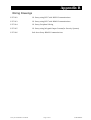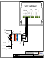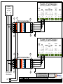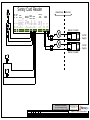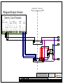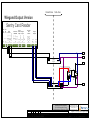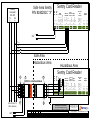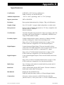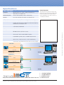
1
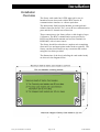
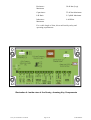
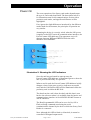
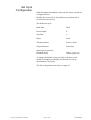
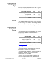
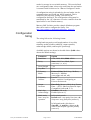
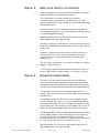
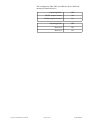
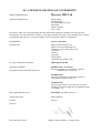
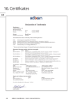
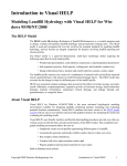
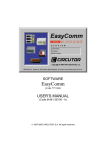
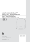
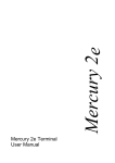
Sentry
Sentry I.S. Card Reader
User Manual
Contact
Mercury HMI Ltd
George House
Derwent Road
Malton
North Yorkshire
YO17 6YB
UK
Tel:
Fax:
Email:
Web
Skype:
+44 (0) 1653 697 200
+44 (0) 8700 667 325
[email protected]
www.mercuryHMI.co.uk
mercuryHMI
Revision Information
Rev
Date
1
Changes
Original Release
1.1
Mercury IMC Version
2.0
27 Jul 09
Substantial revision of the manual, for Wiegand O/P Mode, R507
barrier and Modbus enhancements.
2.1
6 Oct 09
All drawings re-drawn
2.2
2 Dec 10
The Digital Output driving page 17 has been revised. Table
boundaries made finite thickness, to help PDF printing
Extra reader type added
Config string updated
Links show Mercury HMI limited & logo. Certificate checked.
2.3
18 Mar 11
Added Special conditions of use
The Sentry Cardreader has special conditions for safe use (denoted by X after the certificate
number) applicable to it. There are 2 conditions applied, see section 15 of the Sira Certificate
shown on page 30.
Mercury HMI Ltd explanation of the special conditions for safe use
1.
The Sentry Cardreader has areas of the enclosure that could generate static under some circumstances,
and if the static were to build up then a spark could result. To avoid this risk, do not clean or polish the
device with a dry cloth or position it where jets of high-pressure steam or other gases could blast over its
surface.
2.
This is a warning that the enclosure is made of LM24 grade Aluminium, and there is the potential for
sparking to occur by impact or friction from objects hitting it. Hence position/protect the unit so that it is
unlikely to be struck.
All trademarks are acknowledged as the property of their respective owners.
This document shall not form part of any contract. Specifications are subject to change without
notice, and Mercury HMI Ltd accepts no liability of any kind for errors or omissions.
Sentry IS Card Reader User Manual
Page 2 of 41
2v2ODT091202
Contents
Introduction .........................................................................................4
Certification Standard ........................................................................5
Installation............................................................................................6
Overview................................................................................................6
Mounting the Sentry Card Reader..........................................................7
Weatherproofing.....................................................................................7
Hazardous Area Connections.................................................................7
Safe Area................................................................................................9
Safe Area Connections..........................................................................10
Operation.............................................................................................11
Power On...............................................................................................11
Set Up & Configuration........................................................................12
Configuring the Card Media Type........................................................13
Configuring The Sentry Card Reader....................................................13
Configuration String .............................................................................14
Example Configuration String..............................................................15
Telemetry Block Structure.................................................................16
Escape Sequences..................................................................................17
Card Media Specifications....................................................................17
System Options....................................................................................18
Option1 - IS Sentry in Stand-alone mode.............................................18
Option 2 - IS Sentry in multi-drop mode..............................................18
Option 3 - IS Sentry in (standard) Modbus mode.................................19
Option 4 - IS Sentry in Mercury 2+ Modbus mode.............................22
Option 5- Safe Area Sentry Connections..............................................23
Option 6 - IS Sentry Wiegand Output mode.........................................23
Hazardous Area I/O Options.............................................................25
Sentry Expansion...................................................................................25
Appendix A - Certificates of Conformity.............................................26
Appendix B - Wiring Drawings............................................................32
Appendix C - Brief Guide to Card Technologies..................................38
Appendix D - Specifications.................................................................39
Appendix E - Sentry Product Flyer.......................................................40
Sentry IS Card Reader User Manual
Page 3 of 41
2v1ODT091006
Introduction
The Sentry card reader system is an Intrinsically Safe card
reader designed to read a variety of different card types in
hazardous areas.
A complete Sentry card reader system comprises of 3 main
components.
•
•
•
A R507 barrier mounted in the safe area
The Sentry Base Unit, with the processing and
communications electronics (P174 Board) affixed in the
hazardous area, connected to the fixed wiring
The Sentry Lid containing the appropriate reader head ( the
reader electronics and a safety barrier encapsulated together
into a module mounted behind the RF transparent window)
and the status LEDS
There are 3 variants of the Sentry Base Units
•
•
•
Hazardous area Serial communications version, supporting
point to point, multi-drop and Modbus communications
standards
Safe area Serial Communication version
Hazardous area Wiegand Output Version. A Wiegand
Output kit comprising of a P510 Module and barriers is also
needed.
Currently there are four Sentry Lids available. These are:-
•
•
•
•
Wiegand Swipe Card
EM Proximity Card
MIFARE Proximity Card
HID Proximity Card ( H10301 & H10306 Format)
Illustration 1: Hazardous area EM Card reader
Sentry IS Card Reader User Manual
Page 4 of 41
2v1ODT091006
Certification Standard
ATEX Number
Copies of SIRA certification No. 99ATEX2138X are
included in Appendix A, showing EEx ia IIC T4, which is
made up as follows:EEx
=
European certificate for hazardous areas.
ia
=
Intrinsically Safe for Zone 0, continuous
Hazardous vapours.
IIC
=
Safe for ALL gas groups.
T4
=
exceed
Component surface temperature cannot
130°C, i.e. safe for all gasses except carbon
disulphide.
The “Conditions of Certification” show the maximum
parameters of each of the input/output terminal blocks.
Nomenclature &
Conventions
In this manual, ASCII single characters which are either
control or non-visible codes (Hexadecimal 00 - 1F, 20 and
7F) are indicated by enclosure in < >, for example, <ESC>.
Character strings which are indivisible sequences are shown
between quotation marks, for example, "<ESC> [ 2 J".
In the ASCII 7 and 8 bit code sets used by Mercury 2+, a
character is represented by two digits, each in the range
hexadecimal 0 to F. For example, <SP>, the space character
is defined (20H).
Sentry IS Card Reader User Manual
Page 5 of 41
2v1ODT091006
Installation
Installation
Overview
The Sentry card reader has ATEX approval for use in
hazardous areas when used with the R507 barrier &
communications interface or a direct equivalent.
The Intrinsically Safe Interface Module provides galvanic
isolation between the 24V D.C. power & host communication
ports and the I.S. hazard area connection
These connections to the Sentry allow a cable length of up to
1 kilometre. The R507 communication ports provide for
RS232 and differential transmit and receive terminals for
RS422/485, with tri-state control.
The Sentry should be ordered as a complete unit comprising
electronics box and appropriate reader head as required. The
Sentry can then be mounted on any convenient flat surface
using the four holes provided.
The dimensions of the box (excluding the card reader head)
are shown in the diagram below.
Illustration 2 Sentry Mounting Hole Centres
Sentry IS Card Reader User Manual
Page 6 of 41
2v1ODT091006
Mounting
the Sentry
To affix the Sentry Card Reader to a surface, prepare by
drilling four holes 204 mm apart in width and 82 mm apart in
height, refer to Illustration 2. Carefully remove the Sentry Lid
containing the reader head and LEDs, supporting the lid so
that the cables are not put under strain. If this is not possible,
carefully remove reader head plug from J2 (see Illustration 4)
and the LED assembly plug from J1 and store the reader head
safely.
Four mounting screws can now be used to attach the Sentry
Base Unit to the mounting surface.
Now plan how the hazardous area wiring is going to be
terminated. For a simple IS installation, when the only
connections are the 4 wires to the Sentry, use the centre gland.
Weatherproofing
The Sentry electronics box and card reader head are weather
proof, so care must be taken to ensure the “O” ring seals are in
place and free from grit when mounting the equipment.
In salty or corrosive areas, it is advisable to grease the lid
screws to avoid binding.
There are three 20mm threaded holes provided in the box for
cable glands. Any unused glands should be fitted with suitable
weather blanking plugs.
In its most basic configuration, Sentry wired to host, only one
cable is needed (See Appendix B drawing number P174’112
and P174'113).
Hazardous Area
Connections
For hazardous area applications, the cable connecting the
R507 barrier & communications interface needs to comply
with the following parameters:
Loop resistance
40 Ω Maximum
Capacitance
142 nF Maximum
L/R Ratio
33 μH/Ω Maximum
Inductance
0.6 mH Maximum
In practice these parameters are easily met by standard cables;
e.g. a 1 mm2 quad cable has approximately the following
parameters:
Sentry IS Card Reader User Manual
Page 7 of 41
2v1ODT091006
Resistance
Maximum
38 Ω /km (loop)
Capacitance
55 nF/km Maximum
L/R Ratio
2.5 μH/Ω Maximum
Inductance
Maximum
0.48 H/km
For a cable length of 1km, this would satisfy safety and
operating requirements.
Illustration 4: Inside view of the Sentry, showing Key Components
Sentry IS Card Reader User Manual
Page 8 of 41
2v1ODT091006
Safe Area
For hazardous area use, the Sentry must be connected to the
R507 barrier & communications interface. The R507 must be
located in the safe area.
An illustration of the interface module, which is designed to
be mounted on a DIN rail, is shown below.
Illustration 3: The R507 IS Power & Comms Isolator
Sentry IS Card Reader User Manual
Page 9 of 41
2v1ODT091006
Safe Area
Connections
For safe area use, the hazardous area parameters are not
applicable and any suitable communications cable can be
used.
In a safe area application, the host can be connected directly to
the Sentry card reader RS422 connections as shown in
Appendix B
The wiring terminals are screw terminals on a 5.08 mm pitch;
each capable of accepting 2mm diameter cores or ferrules.
For connection details of power and signals, see the wiring
diagrams in Appendix B.
Sentry IS Card Reader User Manual
Page 10 of 41
2v1ODT091006
Operation
Power On
The exact operation of the Sentry card reader depends upon
the type of card reader head fitted. The description below is
for a hazardous area Serial communications version with a
proximity card reader, and significant difference will be
highlighted.
If we ignore the slight differences introduced by the different
reader heads for the moment, the principles of operation are
very similar.
Assuming the device is correctly wired, when the 24V power
is applied to the R507 barrier & communications interface, the
Power/Comms LED Indicator (The uppermost one) will
alternate between RED and GREEN whilst the other
indicators will flash RED.
Illustration 5: Showing the LED Indicators
Once the unit has performed its start-up tests, the
Power/Comms LED Indicator is illuminated green to show the
unit is powered and ready for operation.
When a card is read, the Power/Comms LED Indicator briefly
changes colour (from green to red) to indicate a successful
read, and the Card Present LED will be illuminated whilst the
proximity card is within the RF field.
The data from the card is then decoded, and this data is sent
back to the safe area where it is available from the barrier and
communications interface in Serial RS232/422/485 format as
ASCII characters.
The Host Programmable LED can be set to be On, Off or
Flash, utilising commands send using the serial
communications channel by the host to which the Sentry Card
Reader is connected.
Note: although this LED is fitted to all models, it cannot be
controlled in Wiegand output mode.
Sentry IS Card Reader User Manual
Page 11 of 41
2v1ODT091006
Set Up &
Configuration
With the equipment suitably connected, the Sentry can then be
configured for use.
Initially, the set up will be the default set up when a unit is
received from the factory.
The default set up is:
Baud Rate:
9600
Word Length:
8
Stop Bits:
1
Parity:
None
Telemetry Mode:
Point-to-Point
Output Structure:
Data Only
Start/stop bit operation:
Wiegand mode
Proximity mode
Start = 1, stop = 0
Include parity bits
To change the default set up, the links in the Sentry unit
should be changed accordingly and then the new set up
downloaded to the Sentry.
The link configurations are shown on page 12
Sentry IS Card Reader User Manual
Page 12 of 41
2v1ODT091006
Configuring the
Reader Card
Type
For correct operation jumper links LK2 and LK3 on the card
reader main board must be set to correspond with the type of
card reader head fitted as follows :
Card Reader Head Type
LK3
LK2
Proximity EM or MIFARE
Off
Off
Proximity HID
Off
On
Reserved (for future use)
On
Off
Wiegand
On
On
NOTE:
The Card Reader Head Type link settings will be correct when
the unit is received from the factory and only needs changing
if the lid is changed for a different card technology.
The board must be restarted for these settings to take effect.
Configuring the
Sentry Card
Reader
The card reader has three configuration modes: Run as Default
Configuration, Load New Configuration and Run as
Configured. This is determined by the position of bit links
LK6 and LK5 at start-up:
Operating Mode
LK6
LK5
Run as Configured
Off
Off
Reserved (for future use)
Off
On
Load New Configuration
On
Off
Run as Default Configuration
On
On
Illustration 4 on page 8 shows the positions of the links on the
main Sentry PCB together with their functions is shown in
Appendix B.
The “Run as Configured” mode configures the Sentry Card
Reader using the last stored user configuration.
The "Run as Default Configuration" mode over-rides any user
configuration, and hence gives a known setup to allow
communications to be established.
The “Load New Configuration” mode also starts the card
reader with the default settings loaded, but in addition it
allows new configuration data to be uploaded to the card
Sentry IS Card Reader User Manual
Page 13 of 41
2v1ODT091006
reader for storage in non-volatile memory. This user defined
new configuration data is then only used when the card reader
is restarted with bit links set for “Run as Configured” mode.
A configuration string is uploaded to the card reader via the
communications port using any ASCII terminal. This is
initiated by the keyword “config” followed by the
configuration data itself. The configuration string must be
terminated by the “@” character to invoke a transfer from the
input buffer to non-volatile memory.
Mercury IMC Ltd also provide a simple Windows program
that can be used to configure the Sentry. See
http://www.mimc.co.uk/downloads/sentry_tester.zip
Configuration
String
The string follows the following format:
config baud rate,parity,word length,number of stop bits;
telemetry mode[,telemetry address]; output structure;
acknowledge enable; start/stop bit operation@
Available options are shown in the table below (bold values
denote the default setting).
Parameter
Option
Baud Rate
1200, 2400, 4800, 9600, 19200
Parity
None, Odd, Even, Mark, Space
(sent as n, o, e, m, s)
Word Length
7, 8
Stop Bits
1, 2
Telemetry
Mode
Point-to-Point, Multi-drop, Modbus,
Mercury 2+ Modbus
(sent as pp, md, mb, m2)
Telemetry
Address
1 to 64
Note : omit this if configuring as
Point-to-Point mode
Output
Structure
Data Only, Mercury Multi-drop Format,
Data + <ETX> (Mercury Barcode Input
Compatible) (sent as 0, 1, 2)
Muti-drop
Acknowledge
Disabled (sent as 0)
Enabled (sent as 1)
Multi-mode
Start / stop bit
operation
In Proximity mode:Include start / stop parity bits (sent a 0)
Strip start / stop parity bits (sent as 1)
In Wiegand mode, this detects:Start bit = 1, stop bit = 0 (sent as 0)
Start bit and stop bit opposite polarity
(sent as 1)
Sentry IS Card Reader User Manual
Page 14 of 41
2v1ODT091006
Example of
Configuration
String
config9600,n,8,1;md,12;0;1;1@
After loading this string into non-volatile memory the card
reader immediately reads it back and transmits it to the host
terminal with the Sentry Base Unit PCB serial number
appended to confirm success of the write. For example, the
user would see:config9600,n,8,1;md,12;0;1;1
Serial #:00000123
Once the string is uploaded the card reader should be restarted
in either ‘Run as Default Configuration’ or ‘Run as
Configured’ mode to prevent accidental writes to non-volatile
memory.
Sentry IS Card Reader User Manual
Page 15 of 41
2v1ODT091006
Telemetry Block Structure
Multi Drop
When Mercury Multi-drop output format is selected, messages
between the Card Reader and host follow the format:“<STX>, ADDR, FUNC, ID, DATA, DMY, CSUM, <ETX>"
<STX> is the Start Transmission character (02 Hex)
ADDR is a two-byte address field. Each byte is the ASCII
equivalent of a number 0 to 9. This number is not relevant
except in multi-drop mode. It is the Telemetry Address and
can take the value 01 to 64.
FUNC is a single byte character used to determine the type of
information being sent. It is always “D” (44 Hex) when
transmitted from the card reader, and “R” (52 Hex) when
transmitted to the card reader.
ID is the identification of the source of the block. It is a single
byte used to distinguish between the various sources of block
data. Possible values are:'B' (42 Hex) if the block contains Wiegand card swipe data.
'E' (45 Hex) if the block contains Digital Input data.
'G' (47 Hex) if the block contains Proximity card swipe data.
'V' (56 Hex) if the block contains Software Version data.
DATA is the field used to send information.
DMY is a single character whose value is chosen to ensure
that the following CSUM byte is not a control character. The
value of DMY is usually 00 Hex but if this would result in the
CSUM being a control character the DMY would be set to 20
Hex
CSUM is a single byte checksum character. This is the 7 bit
negated algebraic sum of all the characters in the string from
the STX up to and including the DMY byte.
<ETX> is the End Transmission character (03 Hex).
Data Only
If “data only” is selected as the output structure, only the hexASCII data is output, with no header or trailer characters.
Barcode
Compatible
Contact the factory if hazardous area connections to a
Mercury 2e or 2+ are required.
Sentry IS Card Reader User Manual
Page 16 of 41
2v1ODT091006
Escape
Sequences
The Card Reader responds to the following escape sequences,
which are a subset of those used by a Mercury Terminal:Send Next Queued Block:
(Multi-drop mode only)
“<ESC>[?9;1z”
Re-Send Last Queued Block:
(Multi-drop mode only)
“<ESC>[?9;2z”
Enable Card Reader in One Shot Mode “<ESC>[?15;4z”
Disable Card Reader:
“<ESC>[?15;5z”
Enable Card Reader:
“<ESC>[?15;6z”
Note: these commands enable / disable the device regardless
of the card media type it is configured to read.
Sample Dig Ins:
“<ESC>[?4z”
Set Dig Outs:
where n is one of the following:0 : Dig Out #1 On
1 : Dig Out #1 Off
2 : Dig Out #2 On
3 : Dig Out #2 Off
“<ESC>[?5;nz”
Read Config:
which returns the configuration
data string and serial number.
“<ESC>[?2z”
Set Host LED:
Clear Host LED:
Flash Host LED:
“<ESC>[?6;1z”
“<ESC>[?6;2z”
“<ESC>[?6;3z”
Read Software Version
“<ESC>[?6;0z”
Card Media
Specifications
Wiegand Cards:
Data Length – 34 bit card with
two parity bits. (8 characters
transmitted from card reader)
Proximity Cards:
Data Length – 26 or 32 bit cards
(6 or 8 characters transmitted
from card reader)
Note that other formats may be supported. Please contact the
factory for further details.
Sentry IS Card Reader User Manual
Page 17 of 41
2v1ODT091006
System Options
There are a number of different ways the Sentry Card Reader
can be used depending upon the requirements of the particular
system.
The following information describes some of these system
options regardless of the type of card reader used as this is
incidental to the system involved.
Option 1
IS Sentry in Stand-alone mode
To operate in this mode, the Telemetry Mode in the
configuration string has been set to "pp" or the Sentry is
running in it's default mode.
This is a very straightforward system option. The Sentry is
connected by a four-core cable directly to the R507 in the safe
area.
This is in turn supplied with a 24V-dc supply and the
information is communicated to the host via RS232/422 or
RS485 depending upon the requirements.
The safe area host device can be any device capable of
communicating using VT100 (serial ASCII) protocol and
electrically compatible with any of the three communications
standards available at the R507.
Drawing No. P174’112 and P174'113 shows the necessary
connections in this configuration. (see Appendix B)
Option 2
IS Sentry in Multi-drop Mode
To operate in this mode, the Telemetry Mode in the
configuration string has been set to "md".
This operation is basically an extension of the stand-alone
mode, and would typically be used where a number of Sentry
units are required to interface to a single port on the host
device.
Up to 64 Sentry units can be connected in this way and they
will respond only when a message is sent to the correct
address.
It is important to note that the “daisy chain” wiring for the
Multi-drop connection is carried out in the safe area.
This is because the four wires in the hazardous area carry both
power and communications and it is therefore impossible
within the constraints of Intrinsically Safe equipment design
to carry sufficient power from one safe area connection to
power a number of Sentry units.
Sentry IS Card Reader User Manual
Page 18 of 41
2v1ODT091006
Drawing No. P173’113 shows the necessary connections in
this configuration for a full duplex host connection allowing
two way data flow simultaneously. (see Appendix B)
Option 3
IS Sentry in (standard) Modbus Mode
To operate in this mode, the Telemetry Mode in the
configuration string has been set to "mb"
This operation is similar to the multi-drop mode, in so much
as it can be used where a number of Sentry units are required
to interface to a single port on the host device, and the units
are wired in exactly the same manner, only the configuration
string used to set up the Sentry would be different.
Below is a table of Modbus registers / coils and their
associated function:-
Type
Short
Address
"Long"
Address
Function
Codes
Command
Read Holding Register
0
40001
FC03
Read Software Version
1
40002
FC03
Read Digital Inputs
2 - 17
40003 40018
FC03
Read Card Reading
0
50001
FC04
Read Software Version
1
50002
FC04
Read Digital Inputs
2 - 17
50003 50018
FC04
Read Card Reading
0
60001
FC05
Enable User LED
1
60002
FC05
Disable User LED
2
60003
FC05
Flash User LED
3
60004
FC05
Enable 1-Shot mode
4
60005
FC05
Disable Card Reader
5
60006
FC05
Enable Card Reader
6
60007
FC05
Clear Card Reading
0
70001
FC06
Set Digital Outputs
1
70002
FC06
Set Command Register
Read Input Register
Force Output Coil
Write Output Register
Sentry IS Card Reader User Manual
Page 19 of 41
2v1ODT091006
Read Input Register 1 using FC03 (or FC04), i.e. Read Digital
Inputs, the bit pattern is:Bit
Function
0
Proximity Switch Input 1
1
Proximity Switch Input 2
2
Digital Input 1
3
Digital Input 2
4
Reserved (read as a 0 in current firmware)
5
Reserved (read as a 0 in current firmware)
6
Card Present Bit
7-15
Reserved (read as a 0 in current firmware)
Write Output Register 1 using FC06 will Set Command
Register. The Command Register bit pattern is:Bit
Operation
0
Enable User LED
1
Disable User LED
2
Flash User LED
3
Enable One-Shot Mode
4
Disable Card Reader
5
Enable Card Reader
6
Clear Card Reading
7-15
Ignored
Note for Bits 0,1 & 2 as well as bits 3, 4 & 5, only one bit
should be set at a time. If more than one bit is set, the highest
bit takes precedence.
Bits
2 1 0
Operation
0 0 1
Enable User LED
0 1 x
Disable User LED
1 x x
Flash User LED
Bits
5 4 3
Operation
0 0 1
Enable One-Shot Mode
0 1 x
Disable Card Reader
1 x x
Enable Card Reader
Once a card has been scanned, it will remain in the “Card
Reading” buffer until it is cleared using Output Coil 6 (Clear
Card Reading).
If the user attempts to scan another card before the current
reading has been cleared, the existing card data is retained and
Sentry IS Card Reader User Manual
Page 20 of 41
2v1ODT091006
the new card data is ignored. To indicate this situation, the
Power/Comms LED will flash 5 times.
When no card has been scanned, the “Card Reading” buffer
will contain all zeros.
Example Modbus
Comms
As an example, to read the Digital Inputs and Card Data, from
a Sentry, that has been set with a Modbus Slave Address of
17, you would send:ADDR
FUNC
Data Start
Reg HO
Data Start
Reg HO
Data # of
Regs HO
Data # of
Regs LO
Error Check
Field
11
03
00
01
00
03
CRC
The response you would get would be:ADDR
FUNC
Byte
Count
11
03
06
Data
Data
Data
Data
Data
Data
Output Output Output Output Output Output
Reg HO Reg LO Reg HO Reg LO Reg HO Reg LO
40002 40002 40003 40003 40004 40004
00
“DI”
A
B
C
D
Error
Check
Field
CRC
The Card Data is read as DCBA.
For example, if A = 55 Hex, B = 20 Hex, C = 01 Hex and D =
00 Hex, then the card data in hex would be 00012055 (Hex) or
73813 (Decimal).
Modbus data
reading sequence
If the host polls the Sentry when no card has been presented,
the card data holding registers will each contain 0000.
If the host polls after a card has been presented, read by the
Sentry and kept in the vicinity of the Sentry, the holding
registers will now contain the card data and the Digital Input
Register will have Bit 6 active.
If the host continues to poll but move the card away from the
Active zone of the Sentry, the holding registers will still show
the data from the last card read, but the Digital Input Register
will have Bit 6 cleared. You will have to issue a Clear Card
Command to reset the card data to all zeros.
Alternatively, if the host issues the Clear Card Command but
leaves the Card in the active zone of the Sentry and then poll
the Sentry, the host will see in the response that the holding
registers will now contain all zeros for the card data and the
Digital Input Register will have Bit 6 active.
Sentry IS Card Reader User Manual
Page 21 of 41
2v1ODT091006
Option 4
Sentry in Mercury 2+ Modbus
Compatibility Mode
To operate in this mode, the Telemetry Mode in the
configuration string has been set to "m2".
This operation is very similar to the standard Modbus mode,
but an alternative mapping is available, to make integration
with Mercury 2+ units simpler. The mapping of the bits within
the registers is the same as standard Modbus mode, only the
register addresses have changed.
Below is a table of Mercury 2+ Modbus registers / coils and
their associated function:-
Type
Short
Address
"Long"
Address
Function
Codes
Command
Read Input Coils
0
30001
FC02
Read Proximity Switch Input 1
1
30002
FC02
Read Proximity Switch Input 2
2
30003
FC02
Read Digital Input 1
3
30004
FC02
Read Digital Input 2
4
30005
FC02
Reserved (read as 0)
5
30006
FC02
Reserved (read as 0)
6
30007
FC02
Read Card Present Bit
7
30008
FC02
Reserved (read as 0)
0
50001
FC04
Read Data Pending
(Bit 15 = Card Present)
1
50002
FC04
Reserved (read as 0)
2-17
50003
FC04
Card Data (ASCII)
18-19
50019
FC04
Card Data
35
50036
FC04
Read Software Version
108
60109
FC05
Clear Card Data Input Buffers
112
60113
FC05
Enable User LED
113
60114
FC05
Disable User LED
114
60115
FC05
Flash User LED
Write Output Register 4
70005
FC06
Set Card Reader Mode
1 = One-Shot
2 = Disable
3 = Enable
5
70006
FC06
Set Digital Outputs
0 = Dig Out #1 On
1 = Dig Out #1 Off
2 = Dig Out #2 On
3 = Dig Out #2 Off
Read Input Register
Force Output Coil
Sentry IS Card Reader User Manual
Page 22 of 41
2v1ODT091006
Option 5
Safe Area Sentry connections
Although designed to be used in hazardous areas, the Sentry is
equally suitable for non-hazardous area use.
The combination of a robust design, long distance
communications, digital inputs, proximity detectors and
digital outputs make its use sensible for other harsh rather than
hazardous area uses.
In this case many of the constraints imposed by hazardous
area equipment legislation can be disregarded, making system
connection altogether simpler.
Drawing number P174’116 shows the system connection for
this configuration. (see Appendix B)
The major difference is that devices can be connected direct to
the Sentry’s RS485/422 terminals rather than through a barrier
of any kind.
Similarly, input/output devices can be connected directly to
the Sentry as long as the power requirements can be met,
without recourse to either flame-proof boxes and safety
characteristics.
The only other requirement for the safe area Sentry is a power
supply of 24V at 100mA.
A 15V-supply output is also available for devices in order to
use the open collector digital outputs or for supply purposes.
Option 6
Wiegand Output Mode
The Sentry can be ordered from the factory with different
firmware that provides a Wiegand output mode, specifically
designed for when a hazardous area card reader is required to
interface with a traditional security and access control system.
The operation of the Sentry in Wiegand Output mode is
entirely different from any of the serial communications mode
detailed above.
For example, neither the User LED nor the Digital Outputs
can be accessed, since there is no way to send information to
the Sentry and neither the card proximity information not the
Digital Inputs nor the Proximity Switch Inputs can be used, as
there is no method of transmitting this info from the Sentry.
The Wiegand D0/D1 data is regenerated and driven out of the
Sentry Digital Outputs. This information can then be sent to
the safe area using a standard switch barrier. As serial
communications are not required, a standard power barrier can
be used to power the Sentry in the hazardous area.
Drawing number P174'115shows the system connection for
this configuration. (see Appendix B)
Sentry IS Card Reader User Manual
Page 23 of 41
2v1ODT091006
The configuration links LK5 and LK6 also have a different
meaning as detailed below:-
Sentry IS Card Reader User Manual
Operating Mode
LK6
D0/D1 outputs normal
Off
D0/D1 outputs inverted
On
Operating Mode
LK5
Reserved
Off
Reserved
On
Page 24 of 41
2v1ODT091006
Hazardous Area I/O
Sentry Expansion
Connections
The Sentry has been designed with system solutions in mind
and as such has input/output capability to interface with other
equipment.
However, it is important to note that any equipment connected
to the Sentry in the hazardous area must not infringe the rules
governing equipment for such areas.
For example, the Sentry digital inputs must only be connected
to equipment that complies with the safety description for the
inputs.
Two Intrinsically Safe NAMUR proximity sensors can be
connected directly to the Sentry Card Reader, using terminals
1 to 3 on terminal block J7. Refer to page 2 of the SIRA
ATEX Certificate in Appendix A to find the hazardous area
terminal characteristics. NOTE J7 is described (from a safety
perspective) as a Proximity Switch Output, since our circuitry
puts a very small, tightly controlled amount of energy out, to
operate the sensor
In addition two whetted Digital Inputs are provide on J8
Terminals 1 to 3, to allow direct connection to simple
equipment such as a microswitch.
Two opto-isolated digital outputs are provided on J10 and J11
which can be used to control annunciators or indicators for
example in the hazardous area.
Sentry IS Card Reader User Manual
Page 25 of 41
2v1ODT091006
Appendix A
Certificates
The EC ATEX DELARATION OF CONFORMITY and the
EC TYPE-EXAMINATION CERTIFICATE for the Sentry
Card Reader from Mercury IMC Limited are shown in the
subsequent 5 pages.
Sentry IS Card Reader User Manual
Page 26 of 41
2v1ODT091006
EC ATEX DECLARATION OF CONFORMITY
Name of Manufacturer
Mercury IMC Ltd
Address of Manufacturer
George House
Derwent Road
York Road Business Park
MALTON
North Yorkshire
YO17 6YB
We declare under our sole responsibility that the undernoted equipment conforms with the protection
requirements of Council Directive 94/9/EC on the approximation of the laws of the member states relating
to equipment and protective systems intended for use in potentially explosive atmospheres.
EQUIPMENT:
Sentry Cardreader
Notified body
SIRA Certification Services
SIRA Test and Certification Ltd
Hazardous Area Centre, Rake Lane,
Eccleston,
Chester
CH4 9JN
ENGLAND
(notified body number 0518)
EC-type examination certificate
SIRA 99ATEX2138X
Applicable standards
EN50014:1997 (A1 and A2)
Electrical apparatus for potentially explosive
ammendments A1 and A2
atmospheres (General Requirements) inc
EN50020:1995
Electrical apparatus for potentially explosive
atmospheres (Intrinsic safety “i”)
EN50284:1999
Special requirements for construction, test and
marking of electrical apparatus of equipment group
II, Category 1 G
Other applicable Directives
89/336/EEC (the EMC directive)
Authorised Person
Mark Chappell
Position
Director
Signature
Place and date of issue
Malton, North Yorkshire 1st August 2004
CERTIFICATION
1
EC TYPE-EXAMINATION CERTIFICATE
2
Equipment intended for use in Potentially Explosive Atmospheres Directive 94/9/EC
3
Certificate Number:
Sira 99ATEX2138X
4
Equipment:
Sentry Cardreader
5
Applicant:
Mercury IMC Limited
6
Address:
George House
Derwent Road
York Road Industrial Estate
Malton
Yorkshire
Y017 6YB
UK
7
This equipment and any acceptable variation thereto is specified in the schedule to this certificate and
the documents therein referred to.
8
Sira Certification Service, notified body number 0518 in accordance with Article 9 of Directive 94/9/EC
of 23 March 1994, certifies that this equipment has been found to comply with the Essential Health
and Safety Requirements relating to the design and construction of equipment intended for use in
potentially explosive atmospheres given in Annex II to the Directive.
Issue:
4
The examination and test results are recorded in the confidential reports listed in Section 14.2.
9
Compliance with the Essential Health and Safety Requirements, with the exception of those listed in
the schedule to this certificate, has been assured by compliance with the following documents:
EN 50014:1997 plus A1 and A2
EN 50020:1994
EN 50284:1999
10
If the sign ‘X’ is placed after the certificate number, it indicates that the equipment is subject to special
conditions for safe use specified in the schedule to this certificate.
11
This EC type-examination certificate relates only to the design and construction of the specified
equipment. If applicable, further requirements of this Directive apply to the manufacture and supply
of this equipment.
12
The marking of the equipment shall include the following:
II 1G
EEx ia IIC T4 (Ta = -40°C to +60°C)
Project Number
C. Index
52A19462
17
C Ellaby
Certification Officer
This certificate and its schedules may only be
reproduced in its entirety and without change.
Sira Certification Service
Page 1 of 4
Form 9400 Issue 1
Rake Lane, Eccleston, Chester, CH4 9JN, England
Tel:
Fax:
Email:
Web:
+44 (0) 1244 670900
+44 (0) 1244 681330
[email protected]
www.siracertification.com
CERTIFICATION
SCHEDULE
EC TYPE-EXAMINATION CERTIFICATE
13
Sira 99ATEX2138X
Issue 4
DESCRIPTION OF EQUIPMENT
The Sentry cardreader is designed to read data from a number of different data storage cards, decode
the information and transmit the data to the non-hazardous area via a suitable interface (e.g. the R007
Interface Module manufactured by Mercury IMC Limited).
The circuitry is housed in a painted aluminium enclosure. There are three cable entries to allow the
access of the supply and communications cables and three LEDs in the cover indicate the status of the
instrument. The Sentry electronics are arranged as follows:
•
the main PCB that contains the voltage regulation, communication and decoding electronics and is
common to all types of cardreader
additional PCBs are unique to the type of card being read
•
Each Sentry is able to read only one type of card, as different hardware is required. The two types of
card reader included in this certification are:
•
Wiegand – a proprietary card-reader (not manufactured by Mercury IMC Limited) mounted on the
cover of the equipment utilising a swipe-card unit.
proximity – a proprietary card-reader (not manufactured by Mercury IMC Limited) utilised by
placing the card over a window on the cover.
•
In addition to the card reading function, there are a number of signal inputs and outputs, as well as
5 V and 15 V outputs. There are two types of signal input:
•
•
digital inputs intended for connection to simple apparatus, e.g. mechanical switches
proximity switch inputs intended for connection to intrinsically safe inductive proximity switches
The Sentry has the following safety description:
J3 (power) or J5 (power supply/comms)
Ui =
28 V
Ii
=
254 mA
Pi =
1.2 W
Ci =
8 nF
Li =
0
J9 (connection to mercury terminal)
Ui
=
29.4 V
Pi
=
1.2 W
Ci
=
57 nF
Li
=
0
Uo =
0
J10,
Ui
Pi
Ci
Li
J4 (power
Ci
=
Li
=
Uo =
Io
=
Po =
Co =
Lo =
J11
=
=
=
=
(digital outputs)
28 V
0.7 W
57 nF
0
output)
0.203 µF
0
12.6 V
254 mA
1.2 W
0.947
250 µH
J7, J8 (proximity switch outputs)
Ui
=
0
Ci
=
10.255 µF
Uo =
6.6 V
Io =
254 mA
Po =
1.2 W
Co =
11.745 µF
Lo/Ro
= 29 µH/Ω *
* No equipment containing inductance may be connected to this output; the Lo/Ro value refers to the
connecting cable
Variation 1 - This variation introduced the following change and was removed by Issue 1:
i.
The introduction of an alternative manufacturing site.
This certificate and its schedules may only be
reproduced in its entirety and without change.
Sira Certification Service
Rake Lane, Eccleston, Chester, CH4 9JN, England
Page 2 of 4
Form 9400 Issue1
Tel:
Fax:
Email:
Web:
+44 (0) 1244 670900
+44 (0) 1244 681330
[email protected]
www.siracertification.com
CERTIFICATION
SCHEDULE
EC TYPE-EXAMINATION CERTIFICATE
Sira 99ATEX2138X
Issue 4
Variation 2 - This variation introduced the following change:
i.
ii.
The recognition of a new proximity card reader design to provide a common replacement item.
To recognise the lower ambient temperature change from -20°C to -40°C.
14
DESCRIPTIVE DOCUMENTS
14.1
Drawings
Refer to Certificate Annexe.
14.2
Associated Sira Reports and Certificate History
Issue
0
1
2
Date
12 October 2000
19 April 2004
30 June 2004
Report No.
R52X6092A
R51V11608A
R51V11045V
3
16 December 2004
R51V11045V
4
19 March 2009
R52A19462A
Comment
The release of the prime certificate.
The introduction of Variation 1
Re-issued to change the name of the applicant as
detailed in report number R51V11045V and to remove
variation 1
Re-issued to correct the name of the equipment at the
request of the applicant
This Issue covers the following changes:
• All previously issued certification was rationalised
into a single certificate, Issue 4, Issues 0 to 3
referenced above are only intended to reflect the
history of the previous certification and have not
been issued as documents in this format.
• The introduction of Variation 2.
15
SPECIAL CONDITIONS FOR SAFE USE (denoted by X after the certificate number)
15.1
Parts of the enclosure are non-conducting and may generate an ignition-capable level of static under
certain extreme conditions. The user should ensure that the equipment is not installed in a location
where it may be subjected to external conditions (such as high-pressure steam) which might cause a
build-up of static on non-conducting surfaces. Additionally, cleaning of the equipment should be done
only with a damp cloth.
15.2
As painted aluminium is used at the accessible surface of this equipment, in the event of rare
incidents, ignition sources due to impact and friction sparks could occur. This shall be considered
when the Sentry cardreader is being installed in locations that specifically require group II, category
1G equipment.
This certificate and its schedules may only be
reproduced in its entirety and without change.
Sira Certification Service
Rake Lane, Eccleston, Chester, CH4 9JN, England
Page 3 of 4
Form 9400 Issue1
Tel:
Fax:
Email:
Web:
+44 (0) 1244 670900
+44 (0) 1244 681330
[email protected]
www.siracertification.com
CERTIFICATION
SCHEDULE
EC TYPE-EXAMINATION CERTIFICATE
16
Sira 99ATEX2138X
Issue 4
ESSENTIAL HEALTH AND SAFETY REQUIREMENTS OF ANNEX II (EHSRs))
The relevant EHSRs that are not addressed by the standards listed in this certificate have been
identified and individually assessed in the reports listed in Section 14.2.
17
CONDITIONS OF CERTIFICATION
17.1
The use of this certificate is subject to the Regulations Applicable to Holders of Sira Certificates.
17.2
Holders of EC type-examination certificates are required to comply with the production control
requirements defined in Article 8 of directive 94/9/EC.
17.3
Resistors R3, R8, R10, and R13 on the proximity card reader shall have a minimum parallel resistance
of 1.93 Ohms. These components are listed on drawings P501'023'F and P174'020.
This certificate and its schedules may only be
reproduced in its entirety and without change.
Sira Certification Service
Rake Lane, Eccleston, Chester, CH4 9JN, England
Page 4 of 4
Form 9400 Issue1
Tel:
Fax:
Email:
Web:
+44 (0) 1244 670900
+44 (0) 1244 681330
[email protected]
www.siracertification.com
Appendix B
Wiring Drawings
P172'112
I.S. Sentry using R507 with RS232 Communications
P172'113
I.S. Sentry using R507 with RS422 Communications
P172'114
I.S. Sentry Peripheral Wiring
P172'115
I.S. Sentry using Wiegand Output Comms(for Security Systems)
P172'116
Safe Area Sentry RS422 Communications
Sentry IS Card Reader User Manual
Page 32 of 41
2v1ODT091006
Sentry Card Reader
Proximity
Switch
Inputs
J9
2 3
J10
1 2
22+
1
1-
4
Digital
Outputs
1+
J8
2 3
Ext Gnd
1
Signal
2+
3
Ext +5V
1+
J7
2
+5V
Common
4
Common
1+
2+
RX+
J6
3
Inter-Haz
Area
Comms
Digital
Inputs
1
IN+
2
RX-
1
IN-
5
TX-
4
OUT-
SCN / Chassis
J5
3
TX+
RX2-
2
OUT+
A-
Ground
(To Host Rx In)
1
Safe-Area
RS422/85
J11
1 2
13
R507 I.S. Interface Module
1 5 9 13
2 6 10 14
3 7 11 15
4 8 12 16
Gnd
(From Host Tx Out)
RX1-
0V
J4
1 2
B-
5
-
TX2+
+24V
J3
2
+
B+
1
-
R507
Comms
TX1+
+
15V
DC
Out
A+
24V
DC
IN
RxIn
16
8
TxOut
Related Product Document
The QAN Responsible Person
must Approve any Changes or ECNs
4
3
2
1
0
Revision
This drawing may not be
reproduced without the consent
of Mercury IMC Ltd
© Mercury IMC Ltd, 2008
Title:
Wiring Diagram – IS Sentry using RS232
14Sep09
Date
MOB
MSC
MPFJ
Initial Drawing
Drawn Chk'd App'd Description
Sheet
1
of
1
Drg No.
P174'112
Sentry Card Reader
1
J9
2 3
J10
1 2
22+
4
1-
J8
2 3
1+
1
Digital
Outputs
Ext Gnd
3
Signal
2+
J7
2
Ext +5V
1+
1
+5V
Common
4
Common
1+
J6
3
Inter-Haz
Area
Comms
Digital
Inputs
Switch
Inputs
2+
RX+
2
Proximity
IN+
1
IN-
5
RX-
4
OUT-
J5
3
TX-
SCN / Chassis
2
TX+
RX2-
1
Safe-Area
RS422/85
OUT+
A-
J4
1 2
B-
-
RX1-
5
J3
2
+
TX2+
1
1
-
R507
Comms
B+
+
15V
DC
Out
TX1+
24V
DC
IN
A+
Master
Computer
RS-422
Tx
Rx
++-
J11
1 2
13
R507 I.S. Interface Module
1 5 9 13
2 6 10 14
3 7 11 15
4 8 12 16
Rx+
RxTx+
Tx-
16
4
Sentry Card Reader
1
J9
2 3
J10
1 2
22+
4
1-
J8
2 3
Digital
Outputs
1+
1
Ext Gnd
3
Signal
2+
J7
2
Ext +5V
1+
1
+5V
Common
4
Common
1+
J6
3
Inter-Haz
Area
Comms
Digital
Inputs
Switch
Inputs
2+
RX+
2
Proximity
IN+
1
RX-
5
IN-
4
TX-
SCN / Chassis
J5
3
OUT-
RX2-
2
TX+
A-
RX1-
1
OUT+
B-
24V -
J4
1 2
TX2+
RxTx+
Tx-
+
-
Safe-Area
RS422/85
J11
1 2
R507 I.S. Interface Module
1 5 9 13
2 6 10 14
3 7 11 15
4 8 12 16
Rx+
RS-422 Bus To
Other Devices
13
5
J3
2
+
B+
1
1
-
R507
Comms
TX1+
+
15V
DC
Out
A+
24V
DC
IN
4
16
Related Product Document
The QAN Responsible Person
must Approve any Changes or ECNs
4
3
2
1
0
Revision
This drawing may not be
reproduced without the consent
of Mercury IMC Ltd
© Mercury IMC Ltd, 2008
Title:
Wiring Diagram – IS Sentry using RS-422
14Sep09
Date
MOB
MSC
MPFJ
Initial Drawing
Drawn Chk'd App'd Description
Sheet
1
of
1
Drg No.
P174'113
Sentry Card Reader
Switch
Inputs
J9
2 3
J10
1 2
22+
1
1-
4
Safe Area
Digital
Outputs
1+
J8
2 3
Ext Gnd
1
Signal
3
Ext +5V
1
+5V
1+
2+
1+
4
Common
2+
Common
RX+
J6
3
Hazard Area
Inter-Haz
Area
Comms
Digital
Inputs
J7
2
IN+
2
Proximity
RX-
1
IN-
5
TX-
4
OUT-
SCN / Chassis
J5
3
TX+
RX2-
2
1
Safe-Area
RS422/85
OUT+
A-
J4
1 2
RX1-
-
TX1+
BLUE
J3
2
+
B+
1
-
A+
+
TX2+
BROWN
R507
Comms
B-
BLUE
24V
DC
IN
15V
DC
Out
J11
1 2
Barrier or Isolator
+
BROWN
24 Vdc
_ Supply
+
24 Vdc
_ Supply
Barrier or Isolator
Related Product Document
The QAN Responsible Person
must Approve any Changes or ECNs
4
3
2
1
0
Revision
This drawing may not be
reproduced without the consent
of Mercury IMC Ltd
© Mercury IMC Ltd, 2008
Title:
Diagram – IS Sentry Peripheral Wiring
14Sep09
Date
MOB
MSC
MPFJ
Initial Drawing
Drawn Chk'd App'd Description
Sheet
1
of
1
Drg No.
P174'114
Hazard Area
Safe Area
Wiegand Output Version
Sentry Card Reader
J9
2 3
J10
1 2
J11
1 2
GND
+24 V
1
2 3
MTL
5021
10 11 12
“1” Out
C
H
A
F
P510
13
7 8 9 10 11 12
“0” Out
14
Related Product Document
The QAN Responsible Person
must Approve any Changes or ECNs
4
3
2
1
0
Revision
D
B
1 2 3 4 5 6
MTL
5015
G
1
22+
4
1-
J8
2 3
Digital
Outputs
1+
1
Ext Gnd
3
Signal
2+
J7
2
Ext +5V
1+
1
+5V
Common
4
Common
1+
J6
3
Inter-Haz
Area
Comms
Digital
Inputs
E
Switch
Inputs
2+
RX+
2
Proximity
IN+
1
RX -
5
IN-
4
TX-
J5
3
OUT-
SCN / Chassis
2
TX+
RX2-
1
Safe-Area
RS422/85
OUT+
A-
RX1-
J4
1 2
B-
-
TX2+
J3
2
+
B+
1
-
R507
Comms
TX1+
+
15V
DC
Out
A+
24V
DC
IN
This drawing may not be
reproduced without the consent
of Mercury HMI Ltd
© Mercury HMI Ltd, 2010
Title:
Diagram – IS Sentry with Wiegand Output
20Dec10
14Sep09
Date
MPFJ
MOB
MOB
MSC
MOB
MPFJ
Added MTL5513 and MTL5521 barriers
Initial Drawing
Drawn Chk'd App'd Description
Sheet
1
of
2
Drg No.
P174'115
Hazard Area
Safe Area
Wiegand Output Version
Sentry Card Reader
J9
2 3
J10
1 2
J11
1 2
GND
+24 V
1
2 3
MTL
5521
10 11 12
“1” Out
C
H
A
F
P510
13
7 8 9 10 11 12
“0” Out
14
Related Product Document
The QAN Responsible Person
must Approve any Changes or ECNs
4
3
2
1
0
Revision
D
B
1 2 3 4 5 6
MTL
5513
G
1
22+
4
1-
J8
2 3
Digital
Outputs
1+
1
Ext Gnd
3
Signal
2+
J7
2
Ext +5V
1+
1
+5V
Common
4
Common
1+
J6
3
Inter-Haz
Area
Comms
Digital
Inputs
E
Switch
Inputs
2+
RX+
2
Proximity
IN+
1
RX -
5
IN-
4
TX-
J5
3
OUT-
SCN / Chassis
2
TX+
RX2-
1
Safe-Area
RS422/85
OUT+
A-
RX1-
J4
1 2
B-
-
TX2+
J3
2
+
B+
1
-
R507
Comms
TX1+
+
15V
DC
Out
A+
24V
DC
IN
This drawing may not be
reproduced without the consent
of Mercury HMI Ltd
© Mercury HMI Ltd, 2010
Title:
Diagram – IS Sentry with Wiegand Output
20Dec10
14Sep09
Date
MPFJ
MOB
MOB
MSC
MOB
MPFJ
Added MTL5513 and MTL5521 barriers
Initial Drawing
Drawn Chk'd App'd Description
Sheet
2
of
2
Drg No.
P174'115
Sentry Card Reader
1
J9
2 3
J10
1 2
22+
4
1-
J8
2 3
1+
1
Digital
Outputs
Ext Gnd
3
Signal
2+
J7
2
Ext +5V
1+
1
+5V
Common
4
Common
1+
J6
3
Inter-Haz
Area
Comms
Digital
Inputs
Switch
Inputs
2+
RX+
2
Proximity
IN+
1
IN-
5
RX-
4
OUT-
J5
3
TX-
SCN / Chassis
2
TX+
RX2-
1
Safe-Area
RS422/85
OUT+
A-
J4
1 2
B-
-
RX1-
J3
2
+
TX2+
1
-
R507
Comms
B+
+
15V
DC
Out
TX1+
24V
DC
IN
A+
Safe Area Sentry
P/N 8180281C “X”
Master
Computer
RS-422
Tx
Rx
++-
J11
1 2
+
24V Tx+
TxRxRx+
Safe Area
Hazardous Area
Hazardous Area
Sentry Card Reader
1
13
5
1
J9
2 3
J10
1 2
22+
4
1-
J8
2 3
Digital
Outputs
1+
1
Ext Gnd
3
Signal
2+
J7
2
Ext +5V
1+
1
+5V
Common
4
Common
1+
J6
3
Inter-Haz
Area
Comms
Digital
Inputs
Switch
Inputs
2+
RX+
2
Proximity
IN+
1
RX-
5
IN-
4
TX-
J5
3
OUT-
2
TX+
1
Safe-Area
RS422/85
OUT+
J4
1 2
SCN / Chassis
-
RX2-
4
J3
2
+
A-
24V -
1
-
RX1-
+
+
B-
RS-422 Bus To
Other Devices
9 13
10 14
11 15
12 16
TX2+
RxTx+
Tx-
5
6
7
8
B+
1
2
3
4
R507
Comms
TX1+
Rx+
15V
DC
Out
A+
R507 I.S. Interface Module
24V
DC
IN
J11
1 2
16
Related Product Document
The QAN Responsible Person
must Approve any Changes or ECNs
4
3
2
1
0
Revision
This drawing may not be
reproduced without the consent
of Mercury IMC Ltd
© Mercury IMC Ltd, 2008
Title:
Wiring Diagram – Safe Area Sentry, RS-422
14Sep09
Date
MOB
MSC
MPFJ
Initial Drawing
Drawn Chk'd App'd Description
Sheet
1
of
1
Drg No.
P174'116
Appendix C
Brief Guide to
Card
Technologies
For all of the card types, it is essential to get the correct type of card
for the reader and also for the specific requirement. As this involves
bit patterns, site codes and frequencies in the case of proximity
cards, it is advisable to contact us before ordering. The cards should
ideally be ordered at the same time as the hardware to avoid
confusion. It is also worth noting that the lead time on security cards
is not inconsiderable; typically 10 weeks.
Security cards can also be ordered with custom artworks, but as this
adds to delivery time and cost it is essential to discuss this prior to
ordering.
Wiegand:
The Wiegand technology relies on the magnetic characteristic
exhibited by a specially constructed wire. A number of wires are
embedded in the card and when they are moved past the reader
head, the magnetic state changes.
This magnetic signature gives each card its number. The advantages
of Wiegand cards is their robust structure and high security due to
the magnetic signature being part of the card’s construction.
The disadvantage of Wiegand cards is the complexity of their
construction and single sourcing, which leads these card to be very
expensive in comparison with proximity cards
Proximity:
The technology used for proximity cards is very different to the
Wiegand technology. In this case, the communication between card
and reader is via. radio waves, so called RFID and thus no physical
contact between card and reader is needed for a card to be read.
The card need only be held close to the reader head for a successful
read to take place. This also allows the ‘card’ to be a variety of
different types e.g. key fobs, as there is no ‘card swipe’ necessary.
The proximity reader also provides an extra digital input which is
used to indicate a Card’s presence.
Which Card to Use?
Sentry IS Card Reader User Manual
This is frequently dictated by site requirements, but where the card
type not predetermined, then in our opinion, we suggest EM cards
for the Far East and MIFARE in the rest of the world unless you
have to be compatible with an existing site system, where we can
provide Wiegand and HID solutions
Page 38 of 41
2v1ODT091006
Appendix D
Specifications
Certification:
ATEX EEx ia IIC T4, Zone 0 (Division 1)
SIRA Certificate. No. 99ATEX2138X.
Ambient temperature:
-20°C to +60°C (operating), -40°C to +70°C (Storage).
Ingress protection:
IP65 to EN 60529.
Enclosure:
Epoxy painted aluminium alloy, Weight 1.7Kg, with EM reader.
Supply voltage:
20 to 32 Volts D.C. at approx 40mA (dependent on reader used).
Data protocol:
Point-to-point and Multi-drop (based on VT-100), compatible with
Mercury 2/2e/2+ Terminal.
Modicon Modbus.
Card formats:
Currently Wiegand swipe cards and a range of proximity cards. The
proximity cards include EM4001 (or compatible), MIFARE and a
range of HID standard formats.
Proximity Inputs:
2 Inputs characterised for direct connection to Namur proximity
switches, utilising the 1.2mA/2.1mA switching levels.
Note: refer to J7 & J8 terminal characteristics on page 2 of the
ATEX certificate in Appendix A for the safety description.
Digital Inputs:
2 general purpose Digital Inputs. These are intended for direct
connection to IS Simple Apparatus, such as a microswitch, but can
be driven by an open-collector or a push-pull TTL output.
Note: refer to J7 & J8 terminal characteristics on page 2 of the
ATEX certificate in Appendix A for the safety description.
Digital Outputs:
2 opto-isolated Digital Outputs. These can sink 25mA and tolerate
up to 28V.
Note: refer to J10 & J11 terminal characteristics on page 2 of the
ATEX certificate in Appendix A for the safety description.
Multi-drop:
Up to 32 Sentry card readers in normal multi-drop mode and 64
units in Modbus mode
Baud rate:
1200 to 19,200 baud with the R507 barrier. The unit is limited to
9,600 baud with the R007 IS Interface.
Mechanical:
Height 122 mm, Width 224 mm,
Depth 85 0mm (Proximity reader) or 125mm (Wiegand reader).
Connections:
IS version, 4-wire connection to R507 IS Interface Module.
(Non IS version*, 2-wire power and 2- or 4-wire communications)
Sentry IS Card Reader User Manual
Page 39 of 41
2v1ODT091006
SENTRY
CARD READER
The Flexible Security Card
Reader for Hostile Areas
Security and Access Control Systems
Wiegand, HID or EM Proximity Cards
Robust All-Weather Protection
Multi-Drop and MODBUS Enabled
The Sentry Card Reader is designed for use in hazardous or harsh environments,
with versions able to read a range of different card technologies.
ATEX Certified to EEx ia IIC T4, the Sentry is Intrinsically Safe (IS) and suitable
for use in the most hazardous of areas, including those classified as Zone 0 (Div.1)
with a constant risk of an explosive atmosphere.
Proximity cards:
A non-contact technology where a card is read by passing it within a few
centimetres of a radio frequency window on the front of the Sentry. With
proximity technology the identification media can take a number of different
formats, including a key fob device as an alternative to the standard Proximity card.
Currently HID and EM4001 (or compatible) devices can be read with a Sentry.
Wiegand cards:
A high security swipe card where data is encoded using wires embedded within the
card during manufacture. Card data cannot be changed or reprogrammed. Wiegand
cards are robust and reliable but relatively expensive.
Operation with Bar Code and Magnetic stripe card technologies is under
development, taking advantage of the Sentry’s modular design.
Intrinsically Safe
Security Card Reader
with Digital Input &
Output Capabilities
Communication with an IS Sentry is via the R007 interface barrier, which can be
located up to 1 km away in a safe area. Host computer connection to the R007 is
made using RS-232, RS-422 or RS-485 signals. (Card data read by a Sentry can
also be sent to a host via a Mercury 2e Terminal, eliminating the need for a second
host port.)
The Safe Area version of the Sentry has RS-422 and RS-485 connectivity available
and does not need the R007 barrier.
Each Sentry can be assigned its own address to allow multi-dropped operation with
RS-422/485 signals. Up to 32 Sentry units can be linked together and connected to
a single control port on the host.
LEDs on the Sentry are used to provide feedback, one is under host control.
EEx ia IIC T4
IP65
II 1 G ATEX Approved
Ingress Protected
The Sentry has 4 digital inputs which can be read by the host. Two are characterised
for use with IS proximity switches and the other two are general purpose Digital
Inputs. The Sentry also has two opto-isolated Digital Outputs, which could be used
to facilitate gate / door entry or initiate an external operation.
Specifications
Further Information
SENTRY CARD READER
The manual and user guides for the Sentry Card
Reader and the other products from Mercury IMC
Ltd can be obtained from our website, directly
from the Headquarters in the UK, or from any of
our distributors worldwide.
ATEX EEx ia IIC T4, (Ta = -20°C to +60°C) Zone 0 (Division 1)
SIRA Certificate. No. 99ATEX2138X
Ambient temperature:
-20°C to +60°C (operating), -40°C to +70°C (Storage)
Ingress protection:
IP65 to EN 60529
Enclosure:
Epoxy painted aluminium alloy, Weight 1.7Kg, with HID reader
Supply voltage:
20 to 32 Volts D.C. at approx 40 mA (dependent on reader used)
Data protocol:
Based on VT-100 (compatible with Mercury 2e Terminal) & Mercury 2e Modbus
Card formats*:
Currently Wiegand swipe cards and HID and EM4001 (or compatible)
proximity card reader heads are available. The Sentry is also designed to
work with barcode and magnetic cards
Inputs:
2 Inputs characterised for direct connection to proximity switches and
2 general purpose Digital Inputs
Outputs:
2 opto-isolated Digital Outputs
Multi-drop:
Up to 32 Sentry Card Readers
Baud rate:
1200 to 9600 baud with existing barriers. Up to 19,200 baud with the
Mk2 R007 IS Interface (and Non IS version*)
Your local distributor:
Communication Interfaces: IS Version- Requires R007 IS Interface Module
Non IS version* - RS422 or RS485. R007 not required
Mechanical:
Height 120.00mm, Width 220.00mm,
Depth 80.00mm (proximity reader) or 110.00mm (wiegand reader)
Connections:
IS version, 4-wire connection to R007 IS Interface Module.
(Non IS version*, 2-wire power and 2- or 4-wire communications)
* Reader heads to suit card formats and IS / Non IS versions are factory configured.
SENTRY ONLY
IS
Interface
Module
4 cores
Sentry IS
Card Reader
RS232/422/485
up to 1 km
24v
HAZARDOUS AREA
SAFE AREA
WITH MERCURY 2e
IS
Interface
Module
Mercury 2e
4 cores
up to 1 km
24v
IS
Interface
Module
4 cores
Sentry IS
Card Reader
HAZARDOUS AREA
24v
SAFE AREA
George House, Derwent Road, York Road Business Park, Malton, North Yorkshire YO17 6YB
t:
f:
e:
w:
+44 (0)1653 697200
+44 (0)8700 667325
[email protected]
www.mimc.co.uk
VT100 is a trademark of Digital Equipment Corporation. MODBUS is a trademark of Gould Modicon. All other trademarks acknowledged. This document shall not form part of any contract.
Specifications are subject to change without notice and Mercury IMC Ltd. accepts no liability of any kind for errors or omissions.
Brochure produced by - Cloud Nine Design 01751 477747 www.cloudninedesign.co.uk
Certification: