1
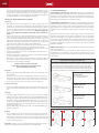
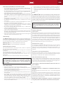
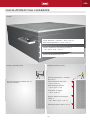
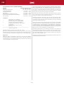
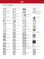
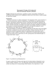
The systematic approach
Safety Instructions
MoA-178-01 | 14.04.2015
INSPECTION LOG
Installer
Installation Date
Place
Date of entry into service
Model description, standard
Batch or serial number
Date
Processing reason (routine examination or maintenance)
Discovered damage, maintenance work carried out, remove
from service and replace etc.
-2-
Name and signature of the
examiner/expert
Next
inspection
USA
Thank You...
Warnings and Limitations:
... for your purchase of ABS Safety fall protection equipment. ABS Safety
products are produced to meet the highest standards using the latest
manufacturing technology.
• This ABS fall protection system complies with ANSI and OSHA.
• Before installing an anchorage connector, carefully inspect it to ensure that it is in a useable condition. Check for missing or damaged
parts. Do not use this equipment if any of the components are not
operating properly or if the unit appears to be damaged in any way.
Please also refer to the inspection section of this manual.
• Only trained or competent personal should install and use this
equipment.
• Ensure that the anchorage connector is installed at a height that
limits the free fall distance to 6 ft. (1.8m) or less.
• The anchorage connector must be compatible with the snap hook
or carabiner of the connecting device. It must not allow a load to be
applied to the gate/keeper.
• Never use an anchorage connector which prevents the snap hook or
carabiner gate/keeper from closing.
• This anchorage connector is designed for use by one person with a
total weight, including tools, of no more than 310 lbs. (140.6 kg) if
following ANSI Z.395 requirements and
• 420 lbs.(190.5 kg) if following OSHA requirements– do not exceed
this weight limit.
• There must be sufficient clearance below the user to arrest a fall
before the user strikes the ground or other obstructions.
WARNING
All persons using this equipment must read and fully understand
all the instructions provided both in the instruction manual and
in this supplement - or have them explained to them. Failure to
comply may results in serious injury or death. Do NOT use this
equipment unless properly trained.
Questions?
Call 1-800-485-1285
This manual is intended to comply with the manufacturer’s instructions
as required by ANSI Z359.1 and should be used as part of an employee
training program as recommended by OSHA.
It is crucial that the person/ user of this fall protection equipment
reads and fully understands these instructions. In addition, it is the
employer´s responsibility to ensure that all users are trained in the
proper use, inspection, and maintenance of fall protection systems.
Fall protection should be a part of a comprehensive safety programm.
Proper use of fall arrest systems can save lifes and reduce the potential
of serious injuries from a fall. The user needs to be aware that forces
experienced during the arrest of a fall or prolonged suspension may
cause bodily injury.
Requirements, Warnings and Limitations
General Requirements:
• All warnings and instructions shall be provided to authorized persons/ users. Warnings and instructions must be read and understood prior to using this equipment.
• Accurate preparation of the working site is necessary. Remove any
obstructions, debris, material, or other recognized hazards from the
work area that could cause injuries or interfere with the operation
of the system.
• All equipment must be inspected before each use according to the
manufacturer´s instructions.
• All equipment should be inspected by a qualified person on a regular basis.
• To minimize the potential for accidental disengagement, a competent person must ensure system compability.
• This system is designed as an attachment point for a personal fall
arrest system to protect the user in the event of a fall. Fall arrest
systems typically include a full body harness and a connecting subsystem (energyabsorbing lanyard, self retracting lifeline).
• As required by OSHA, the personal fall arrest system must be capable of arresting the user’s fall with a maximum arresting force
of 1,800 lbs. (8kN), and limit the free fall to 6 feet (1.8m) or less.
• Never remove product labels as these include important warnings
and information for authorized persons/users.
• Any equipment that has been subjected to damage, or where force
has been asserted through arresting a fall or affecting a rescue,
must be removed from service, as specified by the manufacturer.
• Use only locking carabiners or snap hooks with min. 3,600 lbs.
(16kN) gate load capacity inline with ANSI Z359.1(07) and OSHA.
• The user shall have a rescue plan and the means at hand to implement it when using this equipment.
System Compatibility:
• ABS Safety systems are designed for use with ABS Safety approved
components. Substitution or replacement with non-approved component combinations, sub-systems, or both, may affect or interfere
with the safe function of each other and risk the compatibility within
the system. This incompatibility may affect the reliability and safety
of the total system. ABS Safety requires the use of system compatible body wear. If you are in doubt please contact ABS Safety´s
support 1-800-485-1285. In any way, all instructions and warnings
provided with the equipment must be read and understood before
using the equipment.
Capacity:
• Maximum capacity for single point anchors is one user at a maximum 310lbs (140.6 kg) ANSI Z359 and 420 lbs according to OSHA,
combined tool, clothing and body weight.
• When used as a component within an approved ABS Safety horizontal lifeline system, the lifeline system capacities apply.
Free Fall:
• Personal fall arrest systems must be rigged to limit a free fall to the
shortest possible distance [6 ft (1.8 m) maximum].
• Situations where the 6 ft (1.8 m) will be exceeded, a compatible
lanyard with a shock absorber pack must be used to keep the fall arrest forces at or below 1,800 lbs (8 kN). Free fall must never exceed
12 ft (3.7 m). All standards requirements for a free fall exceeding 6
ft (1.8 m) must be met.
Deformation of the System:
• ABS Safety´s fall protection systems are uniquely engineered. Most
of the system´s are energy absorbing, minimizing the forces imposed on the user and the structure.
Fall Clearance:
• Ensure that the adequate clearance exists in the potential fall path
to avoid striking a lower level or other objects. The potential for a
pendulum fall must be minimized. An extra of 2 ft (0.6 m) of fall
clearance needs to be added to the calculation to account for the
energy absorbing system.
Anchorage Requirements:
Structural requirements:
• An anchorage and anchorage connector selected for a fall arrest
system should be capable of sustaining a static load of at least twice the maximum arrest force permitted on the system where certification exists, or 5,000 lbs. (22.2kN) in the absence of certification.
• An anchorage connector must not be anchored where such attachment would reduce the anchorage capacity to below the applicable
level.
• The structure that the safety system is installed to must be capable
of supporting a 5,000 lbs (22.2 kN) static load in the direction of
loading or meet OSHA requirements for a safety factor of two.
Environmental Hazards:
• Use of this equipment in areas where environmental hazards exist
may require additional precautions to limit the possibility of injury to
-3-
USA
the user or damage to the equipment. Hazards may include, but are
not limited to, extreme temperatures, caustic chemicals, corrosive
environments, high voltage power lines, explosive or toxic gases,
moving machinery, and sharp edges. Do not expose the equipment
to any hazard which it is not designed to withstand.
Inspection, Maintenance and Training
Inspection:
• ABS Safety systems are designed for today´s rugged work environments. To maintain their service life and high performance, all
components should be inspected frequently. Anchorage connectors
must be visually inspected by the user before each use and inspected by a competent person on a regular basis. Replace equipment
if any of the defective conditions explained in this manual are
found.
• Inspect the system for any of the following: bent, cracked, disorted,
worn, malfunctioning or damaged parts; loose fasteners or missing
parts/ components; deteriortion; deformation; corrosion; signs that
indicate the product has been subjected to a fall arrest; or any other
indications of damage/ problems that may affect the integrity and
operation of the product. If in doubt contact ABS Safety.
• Check if all components are attached securly to each other and the
roofs surface and does not show any damage as listed above.
• Check all fasteners and corrosponding torque values to ensure that
it is still meets all anchorage requirements.
• Inspect the condition of the roof to ensure that it still meets all anchorage requirements.
• Inspect the components of the personal fall arrest system according
to the manufacturer´s instructions.
• ABS Safety´s roof anchors should always be in upright position. If
the anchor has been subjected to fall arrest forces the post will be
tipped over in the direction of loading.
System Requirements:
Compatibility of Components: ABS Safety equipment is designed for
use with ABS Safety approved subsystems and components only. Substitutions or replacements made with non-approved components or
subsystems may jeopardize compability of equipment and may effect
the safety and reliability of the complete system.
Compatibility of Connectors: Connectors are considered to be compatible with connecting elements when they have been designed to work
together in such a way that their sizes and shapes do not cause their
gate mechanism to inadvertently open regardless of how they become
oriented. Contact ABS Safety if you have any questions about compability.
Connectors (hooks, carabiners, and D-rings) must be capable of supporting at least 5,000 lbs. (22.2 kN). Connectors must be compatible
with the anchorage or other system components. Do not use equipment that is not compatible. Non-compatible connectors may unintentionally disengage. Connectors must be compatible in size, shape and
strength. Self-locking snap hooks and carabiners are required by ANSI
Z359.1 and OSHA.
Making Connections: Use only self-locking snap hooks and carabiners
with this equipment.
Use only connectors that are suitable to each application. Ensure all
connections are compatible in size, shape and strength. Do not use
equipment that is not compatible. Ensure all connectors are fully closed
and locked.
Devices that do not pass inspection
or have been subjected to fall arresting forces
must be removed from service.
Frequency:
Unintentional Disengagement (Roll-out)
If the connecting element that a snap hock (shown) or carabiner
attaches to is undersized or irregular in shape, a Situation could
occur where the connecting element applies a force to the gate of
the snap hock or carabiner. This force may cause the gate (of either a self- locking or a non-locking snaphock) to open, allowing the
snap hock or carabiner to disengage from the connecting point.
• Before each use: Inspect ABS Safety equipment according to the
points above.
• Annually: A formal inspection of ABS Safety equipment and its connection to the structure must be performed at least annually by a
competent person other than the user. The frequency of formal inspections should be based on conditions of use or exposure.
1. Force is applied to
the snap hook.
(Small ring or other noncompatibility conector)
Cleaning and Storage:
2. The gate
presses against the
connecting ring.
• Basic care of ABS Safety Equipment will prolong the life of the unit
and will contribute toward the performance of its vital safety function.
Servicing:
• Servicing of ABS Safety equipment must only be carried out by ABS
Safety or persons/ entities authorized in writing by ABS Safety. A record log of all servicing and inspection dates for this device must be
maintained. Only original ABS Safety replacement parts are approved for use in ABS Safety equipment. Non-repairable devices that
do not pass inspection must be disposed of in a manner to prevent
inadvertent further use.
• Contact ABS Safety Technical Services at 1-800-485-1285 if you
have any questions.
Training:
• It is the responsibility of the user and the purchaser of this equipment to assure that they are familiar with these instructions, trained in the correct care and use of, and are aware of the operating
characteristics, application limits, and the consequences of improper use of this equipment.
Important: Training must be conducted without exposing the user to a
fall hazard. Training should be repeated on a periodic basis.
-4-
3. The gate opens
allowing t he snap
hook to slip off.
Inappropriate Connections
USA
Additional Requirements for Lifeline Systems:
• All warnings and instructions shall be provided to authorized persons/ users. Warnings and instructions must be read and understood prior to using this equipment.
• All authorized persons/ users must reference the regulations governing occupational health and safety, as well as applicable standards. ABS Lock SYS I-II meet OSHA and ANSI.
• Proper precautions should always be taken to remove any obstructions, debris, material, or other recognized hazards from the work
area that could cause injuries or interfere with the operation of the
system.
• All equipment must be inspected before each use according to the
manufacturer´s instructions.
• All equipment should be inspected by a qualified person at least
once a year.
• To minimize the potential for accidental disengagement, a competent person must ensure system compability.
• Equipment must not be altered in any way. Repair must be performed only by the equipment manufacturer, or persons or entities
authorized, in writing, by the manufacturer.
• Any product exhibiting defomities, unusual wear, or deterioration
must be immediately discarded.
• The user shall have a rescue plan and the means at hand to implement it when using the equipment.
• Never use fall protection equipment for purpose other than those
for which it was designed. Fall protection equipment should never
be used for towing or hoisting.
• Never remove product lables, which include important warnings and
information for the authorized person/ user.
Certification:
The ABS-Lock® SYS fall protection system meets and exceeds the requiremenst set by ANSI/ OSHA, for up to 10 individuals - depending on
the model and type of installation - and complies with the requirements
set by the industrial employers´ liability insurance associations.
ABS-Lock® SYS I for up to 10 individuals simultaneously
ABS-Lock® SYS II for up to 10 individuals simultaneously
• Do not expose the anchorage connector to chemicals or other aggressive substances. If in doubt please contact the manufacturer.
• If there are any doubts as to the safety of the system it should be
immediately taken out of service and sent to the manufacturer for
inspection.
Users:
The ABS-Lock® SYS system was developed to protect individuals from
falls whilst working. In the case of a fall the force exerted on the user is
reduced to what medical experts view as an acceptable level. Only individuals who are familiar with the user manual and are phisically healthy
may use the system. If there are any doubts regarding the users´phisical
condition, please consult a doctor prior to usage. Children and pregnant
women should not use the system.
IMPORTANT: When used as a restraint system with a rope grab
device, the lanyard must be setup in such a way as to make a
fall impossible. ABS does not accept any liability for non-conformance!
Orderly Conditions:
System Checks
The equipment owner and/ or user must always visually check the personal fall arrest protection equipment prior to usage to ensure that it
is in orderly condition and functions properly. The employer must have
personal fall arrest protection equipment checked by a qualified person
as required by the respective implementation and operating conditions
- at least once a year - to ensure it is in perfect condition. Often it is
not possible to examine the whole system before the user attaches
himself/ herself to it. However, should damage, corrosion, deformation
etc. be clearly visible, the system must not be used.
Examination Prior to Usage
Inspection (prior to usage):
The recommendations for the usage of other products in conjuction
with this system must be observed.
All system components must be free from damage with no evidence
of corrosion.
The concrete where the end and intermediate brackets are installed
must be unflawed and have no obvious cracks.
The system must be in good working order without any wear, tear or
deformation.
The system must not be used if the above criteria are not fulfilled.
In accordance with OSHA the ABS-Lock® SYS system must be checked
by a competent person prior to usage - and at least once a year - to
ensure that it is in orderly condition. In exceptional circumstances - depending on the type of implementation - further examinations may be
required.
Safety Harness and Lanyard Examinations
Examine your safety harness, lanyard and hook according to the user
manuals. Onn any account, do not use the equipment if there are signs
of damage or if they have been subjected to fall conditions.
Cable Glider Examination (only SYS II)
Prior to usage examine the SYS II gliders for signs of wear, damage or
corrosion. Confirm that the carabineer hook is attached correctly and is
firmly closed. Only use the glider in combination with the original carabineer and your SYS II fall protection cabling system.
The system must be subjected to an ANNUAL inspection by an
authorized technician which is to be documented accordingly.
This examination is important as the effectiveness and durability of the system is dependent upon it - and consequently the
user´s safety.
Calculation of Cable Deflection and Load in the Case of a
Fall Scenario:
Safety Regulations:
• Never use the system for transporting/ hoisting materials.
• Wherever possible do not work above the anchorage point (please
refer to the lanyard operating manual).
• The ABS system specification plate provides information on the maximum number of simultaneous users.
• This product may only be used by appropriately instructed and trained personnel.
• This product must be used with connectors (in accordance with
ANSI/ OSHA) and personal fall protection equipment (e.g. lanyard
with force absorber according to ANSI/ OSHA, guided type fall arrester with a flexible anchor in compliance with ANSI/ OSHA or a
self-retracting lifeline in accordance with ANSI/ OSHA).
• Following a fall the product must be taken out of service and replaced by a licensed ABS contractor.
Calculation Examples:
Cable deflection/load - calculated for 4 individuals without force
absobtion
Distances between the supports 40 ft. (12 m), total cable length 329
ft. (100 m).
In the case of a fall of 4 individuals this results in 53 in. (134 cm) cable
deflection and maximum load of 3260 lbf (14.5 kN) at the terminal
connections. Additionally, the manufacturer´s guidelines regarding the
respective fall arrest system in accordance with ANSI/ OSHA must be
incorporated in the calculations.
Reducing the number of individuals or usage as a restraint system
can greatly reduce cable deflection and load at the teminal points.
-5-
USA
Examples of cable sag in different system set-ups:
131 ft (40 m) straight run on a concrete substructure using 12 in (300
mm) high posts with a post distance of 32.8 ft (10 m): in this case the
cable sag would be 7.28 ft (2.22 m)
131 ft (40 m) straight run on a rigid steel substructure along a wall
using anchors without protrusion with a post distance of 32.8 ft (10
m) and one force absorber to 8 kN: in this case the cable sag would
be 8.08 ft (2.46 m)
131 ft (40 m) straight overhead run on a concrete substructure anchors
without protrusion with a post distance of 32.8 ft (10 m) and one force
absorber to 8 kN: in this case the cable sag would be 8.08 ft (2.46 m)
IMPORTANT: Please always consider the possible fall distance!
ABS Safety Inc. always recommends that a 3 ft. (1.0 m) safety
factor be added to all fall clearance calculations.
Distance Between Posts in an ABS Lock SYS I-II:
Structure
Concrete
Solid Steel Construction
Trapezoidal Sheeting
Sandwich Sheeting
Seam Roof
Wood Construction (Beams/ Casing)
Prestressed Suspended Concrete Ceilings
Distance between posts
26 - 40 ft. (8 - 12 m)
26 - 40 ft. (8 - 12 m)
23 - 26 ft. (7 - 8 m)
23 - 26 ft. (7 - 8 m)
23 - 26 ft. (7 - 8 m)
23 - 26 ft. (7 - 8 m)
23 - 30 ft. (7 - 9 m)
Calculation:
User approx. 6 ft. (180 cm)
+
Manufacturer´s information for your
fall arrest system acc. to ANSI/ OSHA
+
Change in the length of the cabling
system following a fall
+
Additional safety reserve at least
40 in. (1 m).
______________________________________________________
=
possible fall distance
Distance between the supports 50 - 66 ft. (15 - 20 m):
Generally it is possible to place the supports up to 66 ft. (20 m) apart.
However, this only makes sense in exceptional circumstances. If required
please contact ABS Safety.
-6-
USA
CALCULATION OF FALL CLEARANCE
Example 1
Force Absorber + Lanyard ~ 60 in. (1.5 m)
Self-retracting-lifeline ~ 20 in. (0.5 m)
System Deflection according to table 1
~ 20 - 99 in. (0.5 – 2.5 m)
Safety Distance 40 in (1 m)
Example 2 (Restraint System)
Example 3 (Fall Arrest System)
≥ 2,5 m
No Fall Clearance needed due to
worker restraint.
Standing Disctance + lanyard ~
8 ft. (2 m)
Force Absorber with PPE
~ 60 in. (1,5 m)
Self-retracting-lifeline
~ 20 in. (0,5 - 2 m)
Individual´s Height
~ 71 in. (1,8 m)
System Strech according to
Table 1
~ 20 - 99 in. (0,5 – 2,5 m)
Safety Disctance 40 in. (1 m)
-7-
USA
Calcualation of Fall Clearance EXAMPLE:
Ground
Disctance between posts
Concrete
26 - 40 ft. (8 - 12 m)
Solid Steel Construction
26 - 40 ft. (8 - 12 m)
Trapezoidal Sheeting
23 - 26 ft. (7 - 8 m)
Sandwich Sheeting
23 - 26 ft. (7 - 8 m)
Seam Roof
23 - 26 ft. (7 - 8 m)
Wood Construction (Beams/ Casing)
23 - 26 ft. (7 - 8 m)
Prestressed Suspended Concrete Ceilings
23 - 30 ft. (7 - 9 m)
Gas Concrete
23 - 26 ft. (7 - 8 m)
Personal Fall Arrest System Connectors: Connectors used to attach to
the attachment eyelet or the horizontal lifeline (hooks, carabineers, Drings) must support at least 5,000 lbf (22.2 kN).
Anchorage Connector: Connectors used to attach the horizontal lifeline to end anchors must be compatible with the connection point. The
connection must be positive; and with connection elements, capable of
sustaining 5,000 lbf (22.2 kN).
Calculation:
User approx. 71 in. (180 cm)
+
Manufacturer´s information for your
fall arrest system acc. to ANSI/ OSHA
+
Change in the length of the cabling
system following a fall (pls. refer to Tab.1
on Page 10)
+
Additional safety reserve at least
40 in. (1 m).
______________________________________________________
=
In some situations the user may hold onto the cable for safety reasons.
This is permissible but care should be taken to ensure that not too
much pressure is used as this could lead to deformation of the system.
The system is specially designed to buckle under stress to protect the
supporting structure and the user from being subjected to exessive
force when put under pressure (when someone falls).
Structure Load: Structural anchorage points must be rigid, and capable
of supporting at least 5,000 lbf (22.2 kN) along the axis of the horizontal lifeline system, unless designed by a qualified person. Anchorages
must also support at least 3,600 lbf (16 kN) applied in all potential direction of fall arrest that are perpendicular to the axis of the horizontal
lifeline system, unless designed by a qualified person.
possible fall distance
Distance between the supports 50 - 66 ft. (15 - 20 m):
Generally it is possible to place the supports up to 66 ft. (20 m) apart.
However, this only makes sense in exceptional circumstances. If required and needed for calculations using Table 1 pls. contact ABS Safety.
Application:
ABS-Lock® SYS was developed to provide the user with the greatest
possible freedom of movement. During normal usage the carabineer
smoothly glides over the streches between the supports whilst the user
moves along (SYS I). SYS II glides over.
Connecting Subsystems: The connecting subsystem is the portion of
the personal fall arrest system that is used to connect between the horizontal lifeline subsystem and harness fall arrest attachment element.
The connecting subsystem must limit forces applied to the horizontal
lifeline to 1,800 lbf (8kN) or less.
Putting On and Securing a Lanyard/ Safety Harness: Please refer to the
corrosponding product manuals.
-8-
USA
KEY TO SYMBOLS
i
i
i
!
User and Installation
Manual
Round brush
(wire bristles)
Required rivet type
Please observe the
User and Installation
Manual
Air pump
Safety Manual
Adjustable torque
wrench
Please observe the
Safety Manual!
Torque wrench
with bit
Insert manually
Please use personal
protective fall equipment!
Required jaw width
Sealant/ thread lock
Correct usage
Please observe the
cement instructions!
Screwdriver
Apply sealant/ thread
lock
Wrong usage
Tools
Vacuum cleaner
Cordless screwdriver
Blowtorch
Clean drill hole:
Brush and blow out
Electric drill
Plastic mallet
Concrete adhesive
BLINDNIETE
BLIND RIVET
5,2 x 19,1 mm
3-4x
Hex key xxx mm
Optional components
not included in the
original package.
These can be
purchased from and
supplied by ABS.
6 mm
max
1
Maximum number
of simultaneous
users per anchorage
system
1/3
PSA
i
M20
Tap a thread,
No.: Tap size
!
C 20/25
B 25
Only install in
concrete of
illustrated quality
Steel installation
Hexagonal nut,
No. = Diameter
Hot-air gun
Permissible force
uptake:
Lateral
Installation on wood
Torx-Bit
Angle grinder
Permissible force
uptake:
Axial
Installation on
bitumen
Torque wrench
No. = jaw width
Wire cutter
Permissible force
uptake:
Lateral, both
directions
Installation on PVC
Torque wrench
+ countered
Hand riveter
The drying time stated in the cement
instructions must be
strictly observed!
Counterweighted with
gravel
Spanner
No. = jaw width
Hand riveter with
rivet
User a hammer
Folding ruler
T25
24
ft. lbs.
Warning
Permissible force
uptake:
Axial and lateral
8 mm
Nm
Important
Rubber mallet
24 mm
ft. lbs.
Amount of cement to
be used,
No. = filling level
Drill bit,
No. = Diameter
MATERIAL
Nm
No. of rotations
No. = number
32
Rounded-edge seam
i
24
70 Nm
52 lbf ft
-9-
Tightening torque to
be used,
No. = torque
Standing seam
USA
KEY TO SYMBOLS
Kliptec, Snap seam
Lateral battens
280-333 mm
160-250 mm
Counter lathing
Distance from the
center of two adjacent beads, cold roof
Do not put your full
weight on the rain
gutter. The LaddQuick
is designed to
prevent tipping
Distance from the
center of two adjacent
beads, warm roof
Min. space for opening the toggle bolt
min 0,5 mm
Rafter insulation
Min. thickness of
trapez. sheeting
material
Concrete adhesive:
For overhead installation fix the anchor with
wedges
+5°C
+25°C
Audible acoustic click
CLICK
120mm
Moist substructure
ABS LaddFix: Do not
lean ladder against
the rain gutter
min 60 mm
Roof beam/rafter
10 cm
Concrete adhesive:
Do not use first 10
cm of adhesive
Concrete adhesive:
Store cool and dry
Do not put your full
weight on the rain
gutter. The LaddFix is
designed to prevent
tipping
Restraint system
Use in temperatures
of - to
Sharp-edge tested,
r=Radius
Min. roof beam/
rafter dimensions
Mark drilling spot
Material thickness
Shake well
Min. installation
depth
Material can be bent
max. 5x. Do not bend
more than 5x
Action of heat
Width/distance
Applied Load
Action of cold
Distance to the edge
of the structure
Min. inside ladder
width
Maximum angle of
inclination
Fall protection
60mm
°C
min 6 mm
r=0,5 mm
MAX
max
5x
min.
100 cm
X mm
min.
85 mm
Max.
x mm
max 3°
Maximum gap
Min. inside ladder
width
Consult ABS Safety
Inc.
Cable diameter
Secured using ladder
safety device
To be used as an
end-post in a HLL
Trapezoidal sheeting
cold roof
Danger of falling
without ladder safety
device
To be used as a
corner-post in a HLL
Trapezoidal sheeting
warm roof
ABS LaddQuick:
Do not lean ladder
against the rain
gutter
To be used as a
single point anchor
8 mm
min 20 mm
min 10 mm
Trapez. sheeting:
Min. raised bead
width
Trapez. sheeting: Min.
distance betw. bore
hole and bead edge
To be used in a HLL
Please observe
- 10 -
Concrete adhesive:
Dispose Cap
Temporary anchor
SCRIBBLES & NOTES
- 11 -
The systematic approach
ABS Safety GmbH
Gewerbering 3
D-47623 Kevelaer
Germany
Tel.: +49 (0) 28 32 - 972 81 - 0
Fax.: +49 (0) 28 32 - 972 81 - 29
www.absturzsicherung.de
www.fall-arrest.eu
ABS Safety Inc.
2220 Northmont Parkway, Suite 250
Duluth, GA 30096
U.S.A.
Rh
ein
s
Phone: 1-800-485-1285
Fax.: 1-678-417-6273
www.abs-fall-protection.com
e
L49
1
Niers
raß
Ho
ew
t
pa
ß
str
se
n
eg
d
In
t
us
rie
e
Gew
ring
rt
Stra
ley
nde
hs
Do
t
ra
ge
ld
ße
Ge
er
tra
rS
ne
te
Al
ße
ra
st
er
ße
He
91
L4
Str
aße
K3
0
erbe
ner
Köl
He
S
e
aß
str
en
e
ner
ße
n
on
ß
ra
rs
tra
st
We
tte
e
raß
Bosc h s t
Röm
e
LP 2. Juni 2015
f
aß
9
str
Ho
g
we
en
ex
Ho
ew
og
e
aß
de
ho
hn
Ba
La
ld
Fe
Am
Alte Wettener Straß e
en
nk
he
Sc
Os
ße
Am
KEVELAER
eg
ra
kastra
Ba
hn
s
Basili
ße
Jäg
ers
t
og