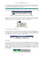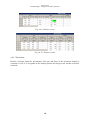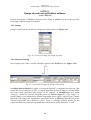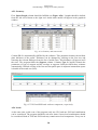
1
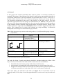
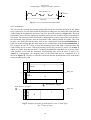
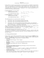
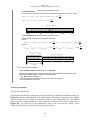
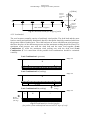
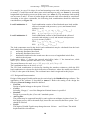
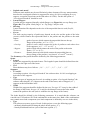
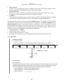
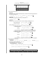
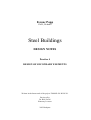
Ferenc Papp
Ph.D., Dr.habil
Steel Buildings
DESIGN NOTES
Practice 4
DESIGN OF SECONDARY ELEMENTS
Written in the framework of the project TÁMOP 421.B JLK 29.
Reviewed by
Dr. Béla Verőci
Honorary Lecturer
2012 Budapest
Ferenc Papp
Steel Buildings – Design of secondary elements
4.1 General
In this project the external trapezoidal sheet and the purlins as secondary elements are
designed. The design of the elements of the façade is based on the same methods, therefore it
is neglected in this project. The design methods are specified by the EN 1993-1-3 Eurocode 3:
Design of Steel structures Part 1-3: Cold-formed thin gauge members and sheeting (EC3-1-3).
The theoretical background of this code is the objective of the MSc courses. The most
important expressions used in the design are summarized in the Table 8. In the practice the
direct use of the theory and methods given by the code may be neglected since the producers
of the products (purlins, sheeting) supply design tables and design software. Design of the
Lindab elements is supported by the DimRoof software which is suggested using in this
project. The software may be safely used without any deep knowledge of theoretical
background on the design of cold-formed thin gauge elements.
Tab.8: Most important expressions used in design theory of cold-formed thin gauge elements
(informative)
special structural properties
Large plate slenderness (b/t)
Partially stiffened plates
One symmetric or no symmetric
cross sections
Relatively thin plates
Special connections
specialties in structural
behavior
- Plate buckling
- „Shear lag” effect*
- Flange induced buckling
- Distorsional instability**
- Lateral torsional buckling
- Flexural-torsional buckling
- Relatively large initial
geometrical imperfections
- Special structural failing
modes
specialties in design
- Class 4 cross-section
- Class 4 cross-section
- Buckling of stiffeners
- Class 4 cross-section
- Global instability
- Plate thickness as parameter
of design
- New design methods based on
tests
*) non-linear normal stress distribution in the flanges due to the shear strains
**) the cross-section looses its shape in the plane of it
The loads for design of purlins and sheeting should be calculated taking the effects of the
slope of roof, the directions of the loads and the constructions into consideration:
dead load and snow load are gravity loads with vertical direction;
wind pressure is perpendicular to the structural plane (eg. to the plane of the roof);
design load consists of transverse loads only (the loads which are parallel with the axis
of elements and which are in the plane of the roof or walls may be neglected).
These rules lead to the reduction of the loads (see Figure 19). It is noted that in case of
relatively small (5o÷10o) slope of roof the approximation of cosα≅cos2α≅1 may be on the safe
side.
2
Ferenc Papp
Steel Buildings – Design of secondary elements
Basic load
[kN/m2]
Design load
[kN/m2]
ps
ps ⋅ cos 2 α
Snow load
p g ⋅ cos α
pw
pg
Dead laod
pw
Slope of roof: α [deg]
Wind load
Edge point
Ridge point
Fig.19 Reduction of loads
4.2 Design of the external trapezoidal sheet
Figure 8 shows the alternative constructions for covering. Both systems have external
trapezoidal sheet which should be designed.
4.2.1 Structural model
The structural model of the external trapezoidal sheet may be approximated by a multispan
continuous beam (see Figure 20), which is perpendicular to the purlins supporting it rigidly.
The reference axis of the model lies in the plane of the roof. The length c1 depends on the
covering system, the length c2 is the distance between the last purlin and the ridge point
(150÷200 mm), but in the practice c1=c2=0 may be used.
c2
c1
Edge of building
Purlins as rigid supports
Ridge point
Fig.20 Structural model for external trapezoidal sheet
Figure 21 shows the cross-section of the beam which is practically defined as 1000 mm wide
part of the sheet. In the case of Lindab products the cross-section is defined by the nominal
depth (eg. LTP45) and the thickness of the plate (eg. t=0,5 mm).
3
Ferenc Papp
Steel Buildings – Design of secondary elements
Plate thickness (t)
Depth
1000 mm
Fig.21 Cross-section for the beam model
4.2.2 Load model
The sizes of the external and internal trapezoidal sheets are normally uniform on the whole
roof, respectively. For the load model the adequate loading area (the load band with 1000 mm
width) along the longitudinal direction of the roof should be found (see Figure 22). The dead
load and the snow load are uniformly distributed, therefore the position of the load band does
not matter. The intensity of the wind load is changing from zone to zone of the roof, therefore
the maximum wind pressure and the maximum wind sucking should be found. The wind
pressure, the dead load and the snow load are the components of the Load Combination 1,
while the wind sucking and the dead load are the components of the Load Combination 2.
For example, in case of 50 slope of roof and assuming cross wind, both of wind pressure and
wind sucking occur on zone J but wind sucking occurs only on zones F and G (see Annex 2)
which are greater than that on zone J. Assuming longitudinal wind there are no zones where
wind pressure occurs and the maximum wind sucking may occur on zones F and G (see
Annex 3). Consequently, the adequate place of the load band may be considered as it is
shown in Figure 22. We have to take the conclusion that the determination of the load model
needs an enthusiastic work.
Case B
I
J
Case A
H
F
G
Ridge line
F
Wind direction: 0 degree
Wind direction: 90 degrees
Ridge line
G
I
H
F
Fig.22 Adequate positions of load bands in case of wind effect
(for 50 slope of roof)
4
Ferenc Papp
Steel Buildings – Design of secondary elements
In the practice we may use approximations at the load model but it should be noted that the
engineer is responsible for the consequences: approximation at side of safe may lead to extra
costs, while approximation at side of unsafe may be against the law. The following two load
combinations may be adequate for the examination of the external trapezoidal sheet in
persistent and transient design situations:
Load Combination 1 (‘pressure load’)
- ultimate limit state (ULS):
- serviceability limit state (SLS):
Load Combination 2 (‘sucking load’)
- ultimate limit state (ULS):
- serviceability limit state (SLS):
γ G ,sup ⋅ p g + γ s ⋅ ps + ψ w.0 ⋅ γ w ⋅ pw.e. pres
pg + ps + ψ w.0 ⋅ pw.e . pres
γ G ,inf ⋅ p g " +" γ w ⋅ pw.e.suck
p g " +" pw.e .suck
The following indices are used in the above expressions:
pg
characteristic value of the uniformly distributed dead load
ps
characteristic value of the uniformly distributed snow load
p w .e
characteristic value of the non uniformly (but uniformly within a zone) distributed
wind load due to cross or longitudinal wind direction, which is the relevant, and “pres”
denotes wind pressure, “suck” denotes wind sucking.
These loads can be calculated directly from the basic loads which were defined for the
building (see Practice 2). The accidental snow load is neglected in this project.
The following partial factors should be used:
γ G ,sup = 1,35 , γ G,inf = 1,0 , γ s = 1,5 , γ w = 1,5
The following combination factor should be used: ψw.0=0,6
The ULS load combination is relevant for checking the resistances, while the SLS load
combination is relevant for checking the deflections, where the suggested limit is L/200 (L is
the span of sheet).
4.2.3 Design and Documentation
Design of thin gauged Lindab trapezoidal sheet may be carried out using the DimRoof design
software. The application of the software is described in Annex 4. Before starting design the
following General Settings (design parameters) should be defined:
Function
Trapezoidal sheet belongs to “Roof” category.
Country
By option of “Hungary” we specify the Hungarian National Annex to be used.
Standard
The design is governed by the „Eurocode” standard system.
Profile
The depth of the Lindab trapezoidal sheet (LTP) may be 20 mm÷150 mm. Here the
adequate depth should be selected.
Extra Sidelap
The type of the sidelap (“no”; “1 trough”; 2 trough” or “double”) is determined by the
architectural engineer. In this project “1 trough” is suggested using.
Default statical model
Lap of sheeting should be avoided in longitudinal direction. The length of the sheets is
limited by the transportability. In this project “continuous” model is suggested.
5
Ferenc Papp
Steel Buildings – Design of secondary elements
The Geometry (geometrical parameters) is defined by the following parameters:
Spans
Thickness of the plate (t=0.4 mm÷0.7 mm);
Type of the supports
Width of the supports (normally it is equal to the width of the flange of the Z section)
The Loads (parameters of loading) are defined by the following parameters:
Type of load
- „U - uniform”: the load acts along the whole beam as uniformly distributed load;
- „L - linear”: the load acts along a part of the beam, and/or its intensity is changing
linearly;
(in the first case only the intensity should be defined, in the second case the
coordinates and the load intensities at the starting and end points of the loaded domain
should be defined)
Load attribute
- „ULS”: load to examine the resistances of element;
- „SLS”: load to examine the deflection of element.
It is noted that the software can take one ULS and one SLS load combinations into
consideration at the same time. Both of the combinations may contain more load components
(one load component is defined by one row in the table).
The analysis and check can be run by the Calculate! button. The results of ULS and SLS are
given in [%]. More details of design may be available by the Relative Results and the
Absolute Results buttons. If one of the results exceeds 100%, or it is less than 50-60%, the
profile should be modified. The modification means change in plate thickness or/and in depth
of sheet. After the modification the analysis and design should be repeated. The final result of
the design may be documented by the following parameters:
Depth of the profile (e.g. LTP 85)
Plate thickness (e.g. t=0,75 mm)
ULS capacity (e.g. 87 %);
SLS capacity (e.g. 92 % with the limit for deflections such as L/200)
4.2.4 Application
3. DESIGN OF COVERING ELEMENTS
In the design project the external trapezoidal sheet and the purlins of the roof system are
designed. Design of the wall elements is neglected.
3.1 Design of external trapezoidal sheet
3.1.1 Geometric model
The external trapezoidal sheet of the roof system is modelled by multispan beam as shown below.
Parameters of the initial trapezoidal sheet: LTP85 t=0,75 mm.
2640
2640
2640
6
2640
Ferenc Papp
Steel Buildings – Design of secondary elements
3.1.2 Load model
Loads are given in [kN/m2] for 1000 mm width of sheet.
3.1.2.1 Characteristic loads
- dead load (self weight of the trapizoidal sheet according to paragraph 2.1)
kN
p g := q tr.ext⋅ cos ( α) = 0.079 ⋅
2
m
- snow load (totally distributed load according to parargraph 2.2.1)
2
p s := s ⋅ cos ( α) = 0.97 ⋅
kN
2
m
- wind load
cross wind (according to parargraph 2.3.3.1)
H - zóna
F - zóna
1,85
4,625
a) wind sucking
pw.0.F.suck := wF.0.1 = −0.931 ⋅
kN
pw.0.H.suck := wH.0.1 = −0.31 ⋅
2
m
kN
2
m
b) wind pressure
kN
pw.0.FGH.pres := wFGH.0 = 0.041 ⋅
2
m
longitudinal wind (according to Section 2.3.3.2)
G - zóna
4,625
F - zóna
1,850
a) wind sucking
p w.90.F.suck := wF.90.1 = −0.869 ⋅
b) wind pressure: negligable
3.1.2.2 Design load combinations
Partial factors
dead load
snow load
wind effect
Combination factors
wind effect
kN
2
m
γ G.sup := 1.35
γ s := 1.5
γ w := 1.5
Ψ w.0 := 0.6
7
p w.90.G.suck := wG.90.1 = −0.828 ⋅
kN
2
m
γ G.inf := 1.0
Ferenc Papp
Steel Buildings – Design of secondary elements
Load Combination 1 : 'Pressure effect' (signed by 'pres')
Effect of gravity (dead and snow) loads is increased by wind effect on zones F and G
kN
p p.ULS := γ G.sup⋅ pg + γ s⋅ ps + Ψ w.0⋅ γ w⋅ pw.0.FGH.pres = 1.599 ⋅
2
m
kN
p p.SLS := p g + p s + Ψ w.0⋅ pw.0.FGH.pres = 1.074 ⋅
2
m
pp.ULS ; pp.SLS
Load Combination 2 : 'Sucking effect' (signed by 'suck')
Maximum wind sucking from longitudinal wind effect
Zone F
kN
kN
p s.ULS.F := γ G.inf⋅ p g + γ w⋅ pw.90.F.suck = −1.225 ⋅
p s.SLS.F := p g + p w.90.F.suck = −0.79 ⋅
2
2
m
m
Zone G
p s.ULS.G := γ G.inf⋅ p g + γ w⋅ p w.90.G.suck = −1.163 ⋅
kN
2
p s.SLS.G := pg + pw.90.G.suck = −0.749 ⋅
m
ps.ULS.F ; ps.SLS.F
ps.ULS.G ; ps.SLS.G
4 625
3.1.2.3 Check of the limit states
Lindab LTP45 t=0,6mm trapezoidal sheet is adequate!
External trapezoidal sheet is checked for ultimate and servicebility limit states using the
DimRoof 3.3 design software. Results of the calculations:
- ULS: 95% (Load Combination 1)
- SLS (with maximum deflection L/200): 67 % (Load Combination 1)
For more details see the Annex.
4.3 Design of purlins
4.3.1 Geometrical model
The structural model of the purlin may be approximated by a multispan continuous beam (see
Figure 23) which is perpendicular to the main frames. The frames support the beam rigidly.
The top flange of the Z purlin is restrained laterally by the trapezoidal sheet. The bottom
flange may be restrained laterally, if the insulation is placed in the room of purlins (see
Figure 8a). The load acts in the intersection point of the web and top flange. These
sophisticated conditions are modeled by the design software.
8
kN
2
m
Ferenc Papp
Steel Buildings – Design of secondary elements
p [kN/m]
Effect of
external
trapezoidal
sheet.
Y
Main frames as supports
Z
Effect of
internal
trapezoidal
sheet, if
there is.
Fig.23 Structural model for design of purlin
4.3.2 Load model
The roof structure normally consists of uniformly sized purlins. The dead load and the snow
load are totally and uniformly distributed, therefore that purlin should be examined which has
the greatest width of loading area. The wind load acts on zones with different wind pressures,
therefore the place of the maximum pressure and the maximum sucking should be found. The
maximum wind pressure acts with the dead load and the snow load together (Load
Combination 1), while the maximum wind sucking acts with the dead load (Load
Combination 2). It is noted that all the possible load combinations should be examined
carefully.
Load Combination 1 (pressure)
Ridge line
H
F
G
F
purlin
Load Combination 2/a (sucking)
Ridge line
H
purlin
Wind
direction
(0 deg)
Load Combination 2/b (sucking)
Ridge line
G
Wind
direction
(90 deg)
H
I
purlin
Fig.24 Load bands for check of purlins
(for purlin system with uniform interval and 100 slope of roof)
9
Ferenc Papp
Steel Buildings – Design of secondary elements
For example, in case of 100 slope of roof and assuming cross wind, wind pressure occurs only
on zones F, G and H but on the other zones wind sucking acts only (see Annex 2). Assuming
longitudinal wind sucking occurs on all the zones (see Annex 3). The maximum wind sucking
acts on zones F and G. In case of purlin design the internal wind effect should be considered.
According to the above statements, the following load combinations should be taken into
consideration (see Figure 24):
Load Combination 1:
Load Combination 2:
Load combination consists of dead load and snow load, and the
effects of external wind pressure (e.press) and internal wind
sucking (i.suck):
ULS: γ G ,sup ⋅ pg + γ s ⋅ ps + ψ 0 ⋅ γ w ⋅ ( pw .e . pres" +" pw.i .suck )
SLS: pg + ps + ψ 0 ⋅ ( pw .e . press" +" pw.i .suck )
Load combination consists of dead load and the effects of
external wind sucking (e.suck) and internal wind pressure
(i.press) at zones F and G:
ULS: γ G ,inf ⋅ p g " +" γ w ⋅ ( pw .e .suck " +" pw.i . press )
SLS: pg " +" ( pw.e .suck " +" pw.i . press )
The load components used in the above load combinations may be calculated from the basic
loads which were determined in Practice 2:
pg
uniformly distributed dead load
ps
uniformly distributed snow load
pw
distributed wind load on the actual zone due to cross or longitudinal wind effect,
which is the relevant.
Furthermore, index “e” denotes the external wind effect, index “i” the internal one, while
index “press” denotes pressure and index “suck” sucking.
The partial factors to be used: γG,sup=1,35; γG,sup=1,0, γS=1,5 és γw=1,5
The combination factor to be used: ψ0=0,6.
The ULS load combination is relevant for checking the member resistances, while the SLS
load combination is relevant for check deflection of members, where the usually used limit is
L/200 (L is the span of the beam). The accidental snow load is neglected in this project.
4.3.3 Design and Documentation
Design of thin gauged Lindab purlin may be carried out by the DimRoof design software. The
application of the software is described in Annex 5. Before the stating of the design the
following General Settings should be defined:
Function
Design of purlin belongs to the option “Z-beam”).
Country
Selecting “Hungary” use of the Hungarian National Annex is specified.
Standard
Design is governed by the „Eurocode” standard system.
Anti-seg bars
The purlins may be supported laterally by anti-seg bars at midspans in plane of roof. In
this design project, due to the small slope, these bars are not used, therefore option “None”
should be selected.
Profile
The depth of Lindab Z purlin may change between 100 mm and 350 mm. The initial
depth should be selected here.
10
Ferenc Papp
Steel Buildings – Design of secondary elements
Default static model
Different static models may be used. Relatively short elements offer easy transportation,
therefore the overlapped solution is suggested for using (10-10% overlapping at every
support, except the second ones at the ends where it is 20%). For this the option of
“Overlapped Standard” should be used.
Lateral Support
Z purlin may be supported laterally at both flanges (see Figure 8a) or at top flange (see
Figure 8b). The option “Both flanges” or “Top flange” may be used.
Sheeting
Lateral restraint effect depends on the size of the trapezoidal sheet is used (Profile,
Thickness).
Screws
The load carrying capacity of purlin may depend on the size and the grade of the bolts
(screws) which connect the trapezoidal sheet to the purlins and the purlins to the main
frames:
- Plate:
grade of screws which connect the trapezoidal sheet to the top
flange of the purlins (“4.8” or “5.5”);
- Overlap:
grade of screws which connect the webs of purlins to each other close
to the supports (“4.8” , “5.5” or “6.3” );
- Support:
grade of bolt which connect the webs of the purlin to the main
frame (“5.5” or “6.3” );
- Distance:
distance between bolts which connect the trapezoidal sheet to
the top flange of the purlins (“one/bottom” or “one/2nd bottom”).
The Geometry of the purlin should be defined by the following parameters:
Spans
Length
Purlins are supported by the main frames. The length of spans should be defined from the
left end to the right end of the beam.
Th.1
Plate thickness may be as follows: „1,0” – „1,2” – „1,5” – „2,0” – „2,5”
Supports
L1 and L2
According to option “Overlapped Standard” the software takes 10-10% overlapping at
both sides of the supports.
Type
Different types of support may be used. According to option “Overlapped Standard” the
software takes hinged (“H”) supports at the ends of the beam, and overlapped (“O” )
supports at the intermediate ones.
Width
Width of the supports should be defined by the user. For type “H” it may be the width of
the flange of the frame, for type “O” it may be the distance between the bolts which
connect the purlin to the stub (stub is welded to the top flange of the frame).
The loads should be defined by the following parameters. It is noted that the software can
consider one ULS and one SLS load combinations at the same time. Both of the combinations
may contain more load components (one load component is defined by one row in the table).
Type
The software uses more types of loads. In this project we use the following types:
- uniformly distributed load along the whole beam (option „U”);
- linearly distributed load on a part of the beam (option „L”).
11
Ferenc Papp
Steel Buildings – Design of secondary elements
Start p./End p.
In case of “L” type load they are the coordinates of the start point and the end point of the
linearly distributed load, taking the direction from left to right.
Start int./End int.
In case of “U” type of load it is the load intensity at the start point. In case of “L” type
load both of the start and end load intensities should be defined.
ULS/SLS
For every load component (for every row) the type of load combination should be defined
(ULS for load carrying capacities, SLS for serviceability capacity calculations).
The analysis and check can be start by the Calculate! button. The results of ULS and SLS
calculations are given in [%]. More details may be available by the Relative Results and the
Absolute Results buttons. If one of the results exceeds 100%, or it is less than 50-60%, the
profile should be modified. The plate thickness or/and the depth of the purlin may be
modified. After the modification the analysis and design should be repeated. The final result
of the design may be documented by the following parameters:
Depth of profile (e.g. Z250)
Plate thickness (e.g. t=1,5 mm)
ULS used part of capacity (e.g. 89%)
SLS used part of capacity (e.g. 94% with the limit for deflections, such as L/200).
4.3.4 Application
3.2 Design of purlins
3.2.1 Geometric model
Purlins are modeled by a many supported beam shown below (initial cross-section):
X
6 000
6 000
6 000
6 000
6 000
6 000
Z 250 (t=2.5 mm)
Y
Z
3.2.2 Load model
3.2.2.1 In general
Intervals between purlins are uniform, therefore the place of the examined purlin does not matter.
Wind pressure and maximum wind sucking occur at zones F and G. Consequently, the purlin
next to the edge beam should be examined for the following two load combinations:
Load Combination 1: pressure loads (signed by 'pres')
Load Combination 2: sucking effect (signed by 'suck')
Width of load area
cL := ea = 2.64 ⋅ m
12
Ferenc Papp
Steel Buildings – Design of secondary elements
cL
purlin to be designed
3.2.2.2 Characteristic loads
Dead load
Self weight of purlin, external trapezoidal sheet, insulation and internal trapezoidal sheet
according to paragraph 2.1:
kN
p g := cL⋅ ( q tr.ext + q tr.int + q ins + qins.other) ⋅ cos ( α) + qpurlin⋅ cos ( α) = 1.212 ⋅
m
Snow load
Totally distrubuted snow load according to paragraph 2.2.1:
kN
2
p s := cL⋅ s ⋅ cos ( α) = 2.56⋅
m
Wind load
Pressure due to cross wind on zones F and G according to paragraph 2.3.3.1:
kN
- external wind effect
pw.e.pres := cL⋅ wFGH.0 = 0.109 ⋅
m
kN
- internal wind effect
pw.i.pres := −cL⋅ wi.0 = 0.22 ⋅
m
Sucking effect:
a) sucking due to cross wind according to paragraph 2.3.3.1:
- external wind effect
kN
zone F
pw.e.suck.F.a := cL⋅ wF.0.10 = −1.421 ⋅
m
kN
zone G
pw.e.suck.G.a := cL⋅ wG.0.10 = −1.093 ⋅
m
- internal wind effect: opposite to external wind effect, it is negligable
b) sucking due to the longitudinal wind according to paragraph 2.3.3.2:
- external wind effect
kN
zone F
pw.e.suck.F.b := cL⋅ wF.90.10 = −1.585 ⋅
m
zone H
zone I
pw.e.suck.H.b := cL⋅ wH.90.10 = −0.71 ⋅
pw.e.suck.I.b := cL⋅ wI.90.10 = −0.86 ⋅
kN
m
kN
m
- internal wind effect: opposite to the external wind effect, it is negligable
3.2.2.3 Design load combinations
Partial factors
dead load: γ G.sup := 1.35 γ G.inf := 1.0
snow load: γ s := 1.5
wind load: γ w := 1.5
Combination factor for wind effect Ψ w.0 := 0.6
Load combinations for two load cases
Load Combination 1 : " Pressure' effect
ppres.ULS := γ G.sup⋅ p g + γ s⋅ p s + Ψ w.0⋅ γ w⋅ ( p w.e.pres + p w.i.pres) = 8.23 ⋅
ppres.SLS := p g + p s + Ψ w.0⋅ ( p w.e.pres + p w.i.pres) = 5.658 ⋅
ppres.ULS ; ppres.SLS
13
kN
m
kN
m
Ferenc Papp
Steel Buildings – Design of secondary elements
Load Combination 2 : 'Sucking' effect (longitudinal wind is the dominant)
kN
p suck.ULS.F := γ G.inf⋅ p g + γ w⋅ p w.e.suck.F.b = −1.164⋅
zone F
m
kN
p suck.SLS.F := p g + p w.e.suck.F.b = −0.372⋅
m
kN
p suck.ULS.H := γ G.inf⋅ pg + γ w⋅ p w.e.suck.H.b = 0.147⋅
zone H
m
kN
p suck.SLS.H := p g + p w.e.suck.H.b = 0.502⋅
m
kN
p suck.ULS.I := γ G.inf⋅ pg + γ w⋅ p w.e.suck.I.b = 0.311⋅
zone I
m
kN
p suck.SLS.I := p g + p w.e.suck.I.b = 0.611⋅
m
psuck.ULS.F ; psuck.SLS.F
psuck.ULS.H ; psuck.SLS.H
4625
psuck.ULS.I ; psuck.SLS.I
4394
3.2.2.4 Check of the limit states
LINDAB Z250 (t=3 mm) purlin is adequate.
Check of ultimate and servicebility limit states was carried out by DimRoof 3.3 software:
Results for pressure effect:
- ULS: 86 %
- SLS: 40 % (for maximum deflection of L/200)
Results for sucking effect:
- ULS: 26 %
- SLS: 6 % (for maximum deflection of L/200)
More details of the calculation can be found in Annex.
14
Ferenc Papp
Steel Buildings – Design of secondary elements
ANNEX 4
Design of trapezoidal sheet using DimRoof software
(User’s Manual)
A4.1 Installation
- download the dimroof_35_install.zip file from the departmental portal
(www.hsz.bme.hu/Oktatás/Magasépítési acélszerkezetek/Gyakorlat)
- unzip the file and run the Dimroof_v3.5_install.exe
- follow the instruction distributed by your lecturer
- run the program using the code given by e-mail
A4.2 How to use the software
After start and selecting language the design window appears. The window is divided into the
following blocks:
General Settings
Structural Settings
Geometry
Loads
Parameters for Deflection Check
The results of the calculation can be found in the Result block. The contents of the blocks are
detailed below.
A4.2.1 General Settings
Design of trapezoidal sheet should be carried out with general settings shown in Figure A4.1.
Fig. A4.1 General settings for design of trapezoidal sheet
A4.2.2 Structural Settings
In Profile box the parameters of cross-section should be defined (eg. LTP45), where the
number denotes the depth of the profile. Cross-sectional parameters are available by Profile
tool (see Figure A4.2).
Fig. A4.2 Cross-sectional parameters available by the Profile tool
15
Ferenc Papp
Steel Buildings – Design of secondary elements
Position of sheet should be defined in Flange Up box, where the adequate option is “Common
(narrow)”. This means that the narrower flange is positioned up. The measure of sidelap is
defined in Extra Sidelap box. In our case option “1 trough” may be selected. This type of
overlap ensures required waterproof. Static model can be defined in Default Static Model
box. Continuous beam model is suggested for using, therefore option “Continuous” should be
selected. This means that the sheet is continuous between ridge point and edge beam. These
settings are shown in Figure A4.3.
Fig. A4.3 Structural Settings for design of trapezoidal sheet
A4.2.3 Geometry
Firstly, we should define the parameters for Span/Length. The lengths of spans should be
written into the boxes, where the stating point is the edge beam. The actual static model is
drawn automatically in the graphical window (see Figure A4.4).
Fig. A4.4 Geometrical parameters with the graphics of actual model
The program fulfils the column of Th.1 automatically. The column contains the uniform plate
thickness of the cross-section. The thickness can be changed by clicking on the first row and
choosing the relevant thickness from the list of usable thicknesses. This thickness will appear
in all the boxes. The program fulfils the column of Supports. The Width is equal to the width
of flange of the purlin. The Width in the first row is greater than in the others because the
width of flange of C formed edge beam is greater than the width of flange of Z formed purlin.
The L1 is the length of the cantilever at the edge beam, while L2 is the distance between the
ridge point and the double purlins.
A4.2.4 Loads
At the same time (within a run of the program) only one ULS and one SLS load combination
can be considered. The program should be run more times, if more load combinations would
be considered. Both of ULS and SLS loads may contain more load components. Every row in
the table defines a load component for ULS or for SLS combinations. For example, Figure
A4.5 shows the definition of an ULS load combination which contains two load components.
16
Ferenc Papp
Steel Buildings – Design of secondary elements
One of them is a partially and uniformly distributed load with -1,23 kN/m intensity, the other
is a partially and uniformly distributed load with -1,16 kN/m intensity. The first load starts at
the edge of the beam and changes at 4625 mm distance.
Fig. A4.5 Definition of ULS load combination with two components
The possible types of load components are shown in Figure A4.6. The type can be selected by
clicking on the first box of the actual row. Option “U” denotes totally and uniformly
distributed load, option “L” denotes partially and linearly distributed load.
Fig. A4.6 Types of load components
A4.2.5 Parameters for Deflection Check
Limit for deflections is not specified by Eurocodes therefore the limit should be defined by
the designer. In this project deflection limit of L/200 is suggested for using (see Figure A4.7).
In the Defl. type box “Maximum” option is suggested choosing. This means that maximum
deflection along the span will be considered as design deflection.
Fig. A4.7 Limit values for deflection check
A4.3 Check
First step of the check of member is the analysis. By Calculation button the program carries
out the analysis and check of model. The used parts of capacities are shown in the Results
boxes (see Fig. A4.8). The member may be considered being designed if the used part both of
the ULS and SLS capacities are less than 100% but one of them is as close to 100% as
possible. The detailed results can be available by the Relative Results (see Fig.A4.9) and
Absolute Results (see Fig. A4.10). Design parameters are the depth and the thickness of the
trapezoidal sheet.
Fig. A4.8 Tools to get results of check and documents
17
Ferenc Papp
Steel Buildings – Design of secondary elements
Fig. A4.9 Relative results
Fig. A4.10 Absolute results
A4.2.7 Documents
Results of design should be documented. The type and form of the document should be
economic in cost. It is acceptable if the student presents the design to the teacher on his/her
notebook.
18
Ferenc Papp
Steel Buildings – Design of secondary elements
ANNEX 5
Design of purlin using DimRoof software
(User’s Manual)
General description of DimRoof software can be found in Annex 4. In this Annex specific
knowledge of purlin design is described.
A5.1 Settings
Design of purlin can be carried out with general settings shown in Figure A5.1.
Fig. A5.1 General settings for design of purlin
A5.2 Structural Settings
Size of purlin (size of the Z section) should be chosen in the Profile box (see Figure A5.2).
Fig. A5.2 Structural Settings for design of the purlin
In Default Statical Model box option “Overlapped Standard” is suggested for select on. This
means that every purlin has 10-10% overlap at right and left sides of support. Overlap makes
the beam being continuous and stronger at the supports. In Manufacturer box option
“Hungary” should be selected. Adequate option for Lateral Support is “Top Flange”, if
bottom flange is not supported by internal trapezoidal sheet. Option “Both Flanges” means
that both of the flanges are supported by trapezoidal sheets. In Sheeting frame the size of the
external trapezoidal sheet should be given. Frame of Screws contains details for the
connection between purlin and trapezoidal sheet and between purlin and frame, as well.
19
Ferenc Papp
Steel Buildings – Design of secondary elements
A5.3 Geometry
First, Spans/Length column should be fulfilled (see Figure A5.4). Lengths should be defined
from the left end of beam to the right end. Actual static model will appear in the graphical
window.
Fig. A5.4 Geometry and static model
Column Th.1 is automatically fulfilled by the software. This parameter denotes the uniform
plate thickness of the purlin. Thickness can be changed by clicking on the first row and
choosing the relevant thickness from the list of usable ones. This thickness will appear in all
the rows. The program fulfils the Supports column. Columns Type, L1 and L2 contain the
parameters of type of support and the overlaps at supports. Software fulfils these columns
automatically. Default overlap of the first and last purlin parts in adjacent intermediate spans
is double of the usual one (20%).
Fig. A5.5 ULS and SLS loads with one component, respectively
A5.4 Loads
At the same time (with a run of the program) only one ULS and one SLS load combination
can be considered. The program should be run more times if more load combinations should
be considered. Both of ULS and SLS loads may contain more load components. Every row in
20
Ferenc Papp
Steel Buildings – Design of secondary elements
the table defines a load component for ULS or for SLS load combination. For example,
Figure A5.5 shows a totally distributed load for ULS combination with 5,77 kN/m intensity,
and a totally distributed load for SLS one with 3,97 kN/m intensity.
A5.5 Parameters for Deflection Check
Limit for deflections is not specified by Eurocodes, therefore the limit should be defined by
the designer. In this project deflection limit of L/200 is suggested for using (see Figure A5.6).
In Defl. type box option “Maximum” is suggested choosing, which means that the maximum
deflection along the span is considered as design deflection.
Fig. A5.6 Settings for check of deflections
A5.6 Check
First step of the check of member is the analysis. By Calculation bottom the program carries
out the analysis and check of model. The used parts of capacities are shown in Results boxes
(see Fig. A5.7). The member may be considered being designed if both of the ULS and SLS
capacities are less than 100% but one of them is as close to 100% as possible. The detailed
results can be available by the Relative Results (see Fig. A5.8) and Absolute Results. Design
parameters are the depth and the thickness of the purlin.
Fig. A5.7 Results and Documents
Fig. A5.8 Relative results
A5.7 Documents
Results of design should be documented. The type and form of the document should be
economic in cost. It is acceptable if the student presents the design to the teacher on his/her
notebook.
21