1
NWP SAF
Satellite Application Facility
for Numerical Weather Prediction
Document NWPSAF-MF-UD-002
Version 7.6, May 2015
AAPP DOCUMENTATION
SOFTWARE DESCRIPTION
AUTHORS :
Tiphaine Labrot (Météo-France)
Nigel Atkinson (Met Office)
Pascale Roquet (Météo-France)
NWP SAF
AAPP DOCUMENTATION
SOFTWARE DESCRIPTION
Doc ID : NWPSAF-MF-UD-002
Version : 7.6
Date
: 06 May 2015
This documentation was developed within the context of the EUMETSAT Satellite Application
Facility on Numerical Weather Prediction (NWP SAF), under the Cooperation Agreement dated 01
December 2006, between EUMETSAT and the Met Office, UK, by one or more partners within the
NWP SAF. The partners in the NWP SAF are the Met Office, ECMWF, KNMI and Météo France.
Copyright 2014, EUMETSAT, All Rights Reserved.
Version
4.0
Date
April 03
4.1
12 May
2003
March
2005
5.0
6.0
7.0
7.1
7.2
7.3
7.4
7.5
7.6
June
2006
Jan
2012
July
2012
Feb
2013
Feb
2014
Aug
2014
Dec
2014
May
2015
Change record
Author / changed by
Remarks
T.Labrot
Version1 of the software description document of AAPP
V4.0
(Follow the version of AAPP V3.0 )
K Whyte
Minor edit
T.Labrot
N C Atkinson
P. Brunel
T.Labrot
N C Atkinson
T.Labrot
N C Atkinson
P Roquet
N C Atkinson
P Roquet
N C Atkinson
P Roquet
N C Atkinson
N C Atkinson
Update for AAPP V5
Add sections on NOAA/CLASS conversion tools and
update MAIA4 section
Updates for MWTS2, MWHS2 and IRAS
P Roquet
Update for MAIA v4.2 release.
N C Atkinson
Update section on hrptdc and add viirs_to_cris.
Update for AAPP V6
Update for AAPP V7
Insert sections on MMAM and modify atovin/atovpp
descriptions, for release of AAPP v7.2.
Add sections on MAIA4
Page 2 /202
NWP SAF
AAPP DOCUMENTATION
SOFTWARE DESCRIPTION
Doc ID : NWPSAF-MF-UD-002
Version : 7.6
Date
: 06 May 2015
TABLE OF CONTENTS
1. INTRODUCTION ................................................................................................... 8
2. DOCUMENTS AND TERMINOLOGY ................................................................... 8
2.1. Applicable and reference documents ............................................................................................................ 8
2.2. Terminology .................................................................................................................................................. 10
3. SOFTWARE ORGANISATION DESCRIPTION .................................................. 12
3.1. Software general organisation..................................................................................................................... 12
3.1.1. The core AAPP ....................................................................................................................................... 12
3.1.2. METOP tools .......................................................................................................................................... 14
3.1.3. IASI tools ................................................................................................................................................ 14
3.2. Interfaces....................................................................................................................................................... 15
3.3. Diagrams ....................................................................................................................................................... 15
3.4. Direct-readout of NOAA satellite data. ...................................................................................................... 16
3.5. Direct-readout of METOP satellite data. ................................................................................................... 18
3.6. Acquisition of METOP data via EUMETCast .......................................................................................... 23
3.6.1. NOAA archived data .............................................................................................................................. 25
4. GENERAL DESCRIPTION................................................................................... 25
4.1. Software main components ......................................................................................................................... 25
4.1.1. Main module for direct-readout of NOAA satellites. AAPP_RUN_NOAA script ................................. 25
4.1.2. Main module for direct-readout of MetOp satellite. AAPP_RUN_METOP script ................................ 26
4.1.3. Main module for FY1 imager data. AAPP_RUN_FY1 script ................................................................ 28
4.1.4. Satellite and image navigation initialisation: Ingest with TBUS bulletin,TBUSING script,
TBUSING.EXE and satellite position and velocity: SATPOST script, SATPOST.EXE ................................. 28
4.1.5. Satellite and image navigation initialization with Two Line Element sets: GET_TLE script, TLEING
script, TLEING.EXE and satellite position and velocity: SATPOSTLE script, SATPOSTLE.EXE. .............. 31
4.1.6. Satellite and image navigation initialization with SPOT-5 element sets (METOP only):
GET_TAI_UT1_UTC script, SPMING script, ADMIN-MAIN.EXE, ADMIN-MESSAGES.EXE and satellite
position and velocity: SATPOSSPM script, SATPOSSPM.EXE. .................................................................... 35
4.1.7. Decommutation modules: DECOMMUTATION script and DECOMMUTATION.EXE. .................... 40
4.1.8. EPS level 0 to AAPP level 1a conversion for METOP: DECOM-AMSUA-METOP script and AMSUAMAIN.EXE, DECOM-MHS-METOP script and MHS-MAIN.EXE, DECOM-AMSUA-HIRS script and
HIRS-MAIN.EXE, DECOM-AVHRR-METOP script and AVHRR-MAIN.EXE. ......................................... 44
4.1.9. Convert chrpt (FY1c and FY1d satellites) ) to hrpt (NOAA satellites): convert_chrpt script and
convert_chrpt.exe.............................................................................................................................................. 46
4.1.10. Image navigation modules: HIRSCL script and HIRSCL.EXE, HIRSCL_ALGOV4 script and
HIRSCL_ALGOV4.EXE, MSUCL script and MSUCL.exe, AMSUACL script and AMSUACL.EXE,
Page 3 /202
NWP SAF
AAPP DOCUMENTATION
SOFTWARE DESCRIPTION
Doc ID : NWPSAF-MF-UD-002
Version : 7.6
Date
: 06 May 2015
AMSUBCL script and AMSUBCL.EXE, MHSCL script and MHSCL.EXE, AVHRCL script and
AVHRCL.EXE. ................................................................................................................................................ 46
4.1.11. HIRS calibration modules (first algorithm): HIRSCL script and HIRSCL.EXE .................................. 48
4.1.12. HIRS calibration modules ( algorithm version 4): HCALCB1_ALGOV4 script and
HCALCB1_ALGOV4.EXE, HIRSCL_ALGOV4 script and HIRSCL_ALGOV4.EXE ................................. 51
4.1.13. MSU calibration modules: MSUCL script and MSUCL.EXE ............................................................. 55
4.1.14. AMSU-A calibration modules : AMSUACL script and AMSUACL.EXE. ......................................... 58
4.1.15. AMSU-B calibration modules: AMSUBCL script and AMSUBCL.EXE. ........................................... 61
4.1.16. MHS calibration modules: MHSCL script and MHSCL.EXE. ............................................................ 64
4.1.17. AVHRR calibration module: AVHRCL script and AVHRCL.EXE. ................................................... 67
4.1.18. ATOVS sounders calibration: ATOVIN script and ATOVIN.EXE ..................................................... 69
4.1.19. Mapping of sounders: ATOVPP script and ATOVPP.EXE. ................................................................ 73
4.1.20. Modify the ATMS beam width: ATMS_BEAMWIDTH script, ATMS_BEAMWIDTH.EXE ........... 91
4.1.21. Modify the MWTS2 or MWHS2 beam width: MWTS2_BEAMWIDTH and MWHS2_BEAMWIDTH
scripts, MWTS2_BEAMWIDTH.EXE and MWHS2_BEAMWIDTH.EXE ................................................... 91
4.1.22. Mapping AVHRR to HIRS + Cloud Mask: AVH2HIRS script , AVH2HIRS.EXE or
AVH2HIRS_ATOVS.EXE............................................................................................................................... 91
4.1.23. AVHRR calibration: AVHRRIN script and AVHRRIN.EXE .............................................................. 97
4.1.24. MAIA3 CLOUD MASK: MAIA3 script and MAIA3_MAIN.EXE .................................................... 99
4.1.25. Convert AVHRR AAPP l1b format to AVHRR PFS L1B format: AAPP-EPS AVHRRL1B script and
EPS_AVHRRL1B-MAIN.EXE. ..................................................................................................................... 105
4.1.26. Convert IASI PFS L1C to IASI AAPP l1c : CONVERT_IASI1C, CONVERT_IASI1C.EXE and
CONVERT_IASI1C_9.0.EXE ....................................................................................................................... 106
4.1.27. Convert NOAA l1b formats to AAPP l1b format: noaa_class_to_aapp script and associated
executables...................................................................................................................................................... 107
4.1.28. Convert AVHRR l1b in AAPP format to NOAA format: avhrr_aapp_to_class script and
avhrr_aapp_to_class.exe ................................................................................................................................. 107
4.1.29. Initialisation before OPS-LRS software: SATPOS-SVM.KSH, SATPOS-SVM.PL ........................ 107
4.1.30. Initialisation before OPS-LRS software: MESSAGES-OSV.KSH, MESSAGES-OSV.PL .............. 108
4.1.31. Navigation tools:SATEPH script, LGEPHEING script and LGEPHING.EXE, LGEPHE script and
LGEPHE.EXE, ALLEPH script and EPHE, TRACKING, ANTCNFT, DRIFTEPHE, TBUSDISP script,
TBUSDISP.EXE, TLEPRINT script, TLEPRINT.EXE................................................................................. 108
4.1.32. BUFR tools (AAPP_DECODEBUFR_1C script and AAPP_DECODEBUFR_1C.EXE,
AAPP_ENCODEBUFR_1C script and AAPP_ENCODEBUFR_1C.EXE) .................................................. 113
4.1.33. HDF5 tools (CRIS_SDR script and CRIS_SDR.EXE, ATMS_SDR script and ATMS_SDR.EXE,
MWTS_SDR script and MWTS_SDR.EXE, MWHS_SDR script and MWHS_SDR.EXE,
AVH1B_TO_HDF5 script, AVH1B_TO_HDF5.EXE, etc.) .......................................................................... 114
4.2. Interfaces..................................................................................................................................................... 116
4.2.1. User input parameters in ATOVS_ENV/ATOVS_ENV7 .................................................................... 116
4.2.2. Inputs/outputs for TBUSING navigation initialisation ......................................................................... 116
4.2.3. Inputs/outputs for GET_TLE navigation initialization ......................................................................... 117
4.2.4. Inputs/outputs for GET_TAI_UT1_UTC navigation tool ................................................................... 117
4.2.5. Inputs/outputs for TLEING navigation initialisation ............................................................................ 118
4.2.6. Inputs/outputs for SPMING navigation initialisation ........................................................................... 118
4.2.7. Inputs/outputs for SATPOST navigation initialisation ......................................................................... 119
4.2.8. Inputs/outputs for SATPOSTLE navigation initialisation .................................................................... 120
4.2.9. Inputs/outputs for SATPOSSPM navigation initialisation.................................................................... 121
4.2.10. Inputs/outputs for decommutation (DECOMMUTATION) ............................................................... 122
4.2.11. Inputs/outputs EPS level 0 format to AAPP level 1a format .............................................................. 123
4.2.12. Inputs/outputs ATOVS and AVHRR navigation (HIRSCL, HIRSCL_ALGOV4, MSUCL,
AMSUACL, AMSUBCL, MHSCL, AVHRCL) ............................................................................................ 124
4.2.13. Inputs/outputs HIRS calibration (first algorithm) (HIRSCL) ............................................................. 125
4.2.14. Inputs/outputs HIRS calibration algorithm version 4 – part 1 (HCALCB1_ALGOV4) ..................... 126
4.2.15. Inputs/outputs HIRS calibration algorithm version 4 – part 2 (HIRSCL_ALGOV4) ......................... 127
4.2.16. Inputs/outputs MSU calibration (MSUCL)......................................................................................... 128
Page 4 /202
NWP SAF
AAPP DOCUMENTATION
SOFTWARE DESCRIPTION
Doc ID : NWPSAF-MF-UD-002
Version : 7.6
Date
: 06 May 2015
4.2.17. Inputs/outputs AMSU-A calibration (AMSUACL) ............................................................................ 130
4.2.18. Inputs/outputs AMSU-B calibration (AMSUBCL) ............................................................................ 131
4.2.19. Inputs/outputs MHS calibration (MHSCL)......................................................................................... 133
4.2.20. Inputs/outputs AVHRR calibration (AVHRCL) ................................................................................. 134
4.2.21. Inputs/outputs sounders calibration application (ATOVIN) ............................................................... 135
4.2.22. Inputs/outputs sounders mapping(ATOVPP) ..................................................................................... 137
4.2.23. Inputs/outputs for mapping cloud mask AVHRR to HIRS (AVH2HIRS).......................................... 140
4.2.24. Inputs/outputs sounders calibration application (AVHRRIN) ............................................................ 143
4.2.25. Inputs/outputs sounders calibration application (MAIA3_MAIN) ..................................................... 144
4.2.26. Inputs/outputs for conversion AVHRR AAPP l1b format to AVHRR PFSL1B format (aappeps_avhrrl1b) .................................................................................................................................................. 145
4.2.27. Inputs/outputs for SATEPH navigation tool. ...................................................................................... 145
4.2.28. Inputs/outputs for LGEPHEING navigation tool ................................................................................ 146
4.2.29. Inputs/outputs for LGEPHE navigation tool ....................................................................................... 147
4.2.30. Inputs/outputs for ALLEPH navigation tool ....................................................................................... 147
4.2.31. Inputs/outputs for TBUSDISP navigation tool .................................................................................. 149
4.2.32. Inputs/outputs for TLEPRINT navigation tool .................................................................................. 149
4.2.33. Inputs/outputs for EPHE, TRACKING, ANTCNFT, DRIFTEPHE navigation tool .......................... 150
4.3. Dynamic articulation ................................................................................................................................. 150
4.3.1. Description of the main script AAPP_RUN_NOAA ............................................................................ 150
4.3.2. Description of the script CHK1BTIME ................................................................................................ 151
4.3.3. Description of the script TBUSING ..................................................................................................... 151
4.3.4. Description of the script GET_TLE ...................................................................................................... 151
4.3.5. Description of the script GET_TAI_UT1_UTC ................................................................................... 151
4.3.6. Description of the script TLEING ........................................................................................................ 151
4.3.7. Description of the script SPMING ........................................................................................................ 152
4.3.8. Description of the script SATPOST ..................................................................................................... 152
4.3.9. Description of the script SATPOSTLE................................................................................................. 152
4.3.10. Description of the script SATPOSSPM .............................................................................................. 153
4.3.11. Description of the script DECOMMUTATION ................................................................................. 153
4.3.12. Description of the scripts HIRSCL, HIRSCL_ALGOV4, MSUCL, AMSUCL, AMSUBCL, MHSCL,
AVHRCL ........................................................................................................................................................ 155
4.3.13. Description of the script ATOVIN ..................................................................................................... 155
4.3.14. Description of the script ATOVPP ..................................................................................................... 156
4.3.15. Description of the script AVH2HIRS ................................................................................................. 157
4.3.16. Description of the script AVHRRIN.KSH .......................................................................................... 157
4.3.17. Description of the script MAIA3.KSH ............................................................................................... 157
4.3.18. Description of the script MAIA3_RUN.KSH ..................................................................................... 158
4.3.19. Description of the script EPS_AVHRRL1B-MAIN ........................................................................... 158
4.3.20. Description of the script EPS_CONVERT_IASIL1C ........................................................................ 158
4.3.21. Description of the script NOAA_CLASS_TO_AAPP ....................................................................... 158
4.3.22. Description of the script AVHRR_AAPP_TO_CLASS ..................................................................... 158
4.3.23. Description of the script SATPOS-SVM ............................................................................................ 158
4.3.24. Description of the script MESSAGES-OSV ....................................................................................... 159
4.3.25. Description of the script SATEPH ...................................................................................................... 159
4.3.26. Description of the script LGEPHEING .............................................................................................. 159
4.3.27. Description of the script LGEPHE ..................................................................................................... 160
4.3.28. Description of the script ALLEPH ..................................................................................................... 160
4.3.29. Description of the command EPHE .................................................................................................... 160
4.3.30. Description of the command TRACKING ......................................................................................... 161
4.3.31. Description of the command ANTCNFT............................................................................................ 161
4.3.32. Description of the command DRIFTEPHE ........................................................................................ 161
4.3.33. Description of the script TBUSDISP .................................................................................................. 161
4.3.34. Description of the script TLEPRINT .................................................................................................. 161
4.3.35. AVHRR and HIRS level 1b file verification : PRHAVH and PRHIRS ............................................. 162
Page 5 /202
NWP SAF
AAPP DOCUMENTATION
SOFTWARE DESCRIPTION
Doc ID : NWPSAF-MF-UD-002
Version : 7.6
Date
: 06 May 2015
4.3.36. MSU level 1b file header verification PRHMSU ............................................................................... 162
4.3.37. DCS level 1b file verification PRHDCS ............................................................................................. 162
4.3.38. Source file identification: HRPTIDF .................................................................................................. 163
4.3.39. Level 1b products identification: L1BIDF .......................................................................................... 163
4.3.40. Level 1c products identification: L1CIDF .......................................................................................... 163
4.3.41. Level 1d products identification: L1DIDF.......................................................................................... 163
4.3.42. Write out a message: LIBLOG ........................................................................................................... 164
4.3.43. Get the orbit number: SDH2ORBNUM.............................................................................................. 164
4.3.44. Decode 1c BUFR files: AAPP_DECODEBUFR_1C ......................................................................... 164
4.3.45. Encode 1c BUFR files : AAPP_ENCODEBUFR_1C ........................................................................ 165
4.3.46. Decode Sensor Data Record files for ATMS, CrIS, MWTS, MWHS, MWTS2, MWHS2, IRAS ..... 165
4.3.47. FY-3 mapping tools: mwhs_to_mwts, mwhs2_to_mwts2, mwts2_to_mwhs2, mwts2_to_iras,
mwhs2_to_iras ................................................................................................................................................ 166
4.3.48. is-mmam .exe ...................................................................................................................................... 166
4.3.49. mmam-main .exe ................................................................................................................................ 166
4.3.50. print-mmam-obt-utc.pl ........................................................................................................................ 167
4.3.51. patch-level0-from-mmam.exe ............................................................................................................. 167
4.3.52. atms1c_print_nedt ............................................................................................................................... 167
4.4. VIIRS tools and MAIA4 ............................................................................................................................ 167
4.4.1. Decode and concatenate Sensor Data Record granule files for VIIRS ................................................. 167
4.4.2. Decode EDR IMG granule files for VIIRS ........................................................................................... 168
4.4.3. The Fortran90 aapp_viirs API .............................................................................................................. 169
4.4.4. MAIAv4 CLOUD MASK : Run MAIAv4 on VIIRS SDR files .......................................................... 173
4.4.5. VIIRS to CrIS mapping ........................................................................................................................ 201
Figures
FIGURE 3-1 : FIRST STEPS FOR TREATING NOAA DATA ......................................................................... 16
FIGURE 3-2 : SECOND STEPS FOR TREATING NOAA DATA .................................................................... 17
FIGURE 3-3 : PRE-PROCESSING STEPS FOR NOAA DATA ........................................................................ 18
FIGURE 3-4 : PERIODICAL STEP FOR TREATING METOP DATA ............................................................. 19
FIGURE 3-5 : FIRST STEPS FOR TREATING METOP DATA (ATOVS PART) ........................................... 19
FIGURE 3-6 : SECOND STEPS FOR TREATING METOP DATA (ATOVS PART) ...................................... 20
FIGURE 3-7 : FIRST STEPS FOR TREATING METOP DATA (IASI PART) ................................................. 21
FIGURE 3-8 : PRE-PROCESSING STEPS FOR METOP DATA ...................................................................... 22
FIGURE 3-9 : CHAIN FOR TREATING METOP -ATOVS DATA RECEIVED VIA EUMETCAST ............. 23
FIGURE 3-10 : CHAIN FOR TREATING METOP –AVHRR - HIRS DATA RECEIVED VIA EUMETCAST
...................................................................................................................................................................... 24
FIGURE 3-11 : CHAIN FOR TREATING ARCHIVED NOAA DATA ............................................................. 25
FIGURE 4-1 : FLOW CHART ON THE COMPONENTS OF THE TBUSING MODULE ............................... 28
FIGURE 4-2 : FLOW CHART ON THE SATPOST MODULE COMPONENTS.............................................. 30
FIGURE 4-3 : FLOW CHART ON THE COMPONENTS OF THE TLEING MODULE .................................. 32
FIGURE 4-4 : FLOW CHART ON THE SATPOSTLE MODULE COMPONENTS. ........................................ 34
FIGURE 4-5 : FLOW CHART ON THE COMPONENTS OF THE SPMING MODULE ................................. 36
FIGURE 4-6 : FLOW CHART ON THE SATPOSSPM MODULE COMPONENTS. ....................................... 38
FIGURE 4-7 : DECOMMUTATION AND HRPTDC MODULE HIERARCHY. .............................................. 40
FIGURE 4-8 : ATOVDC COMPONENTS HIERARCHY. ................................................................................. 41
FIGURE 4-9 : AVHRDC COMPONENTS HIERARCHY. ................................................................................. 42
FIGURE 4-10 : GENERAL FLOW CHART ON THE LOCATION MODULE COMPONENTS :
HIRSCL/MSUCL/AMSUNCL/MHSCL/AVHRCL .................................................................................... 46
Page 6 /202
NWP SAF
AAPP DOCUMENTATION
SOFTWARE DESCRIPTION
Doc ID : NWPSAF-MF-UD-002
Version : 7.6
Date
: 06 May 2015
FIGURE 4-11 : FLOW CHART ON THE HIRSCL MODULE COMPONENTS. .............................................. 49
FIGURE 4-12 : FLOW CHART ON THE HIRSCL_ALGOV4 MODULE COMPONENTS. ............................ 52
FIGURE 4-13 : FLOW CHART ON THE MSUCL MODULE COMPONENTS. .............................................. 56
FIGURE 4-14 : FLOW CHART ON THE AMSUCL MODULE COMPONENTS. ........................................... 59
FIGURE 4-15 : FLOW CHART ON THE AMSUBCL MODULE COMPONENTS.......................................... 62
FIGURE 4-16 : FLOW CHART ON THE AMSUBCL AND MHSCL MODULE COMPONENTS. ................ 65
FIGURE 4-17 : FLOW CHART ON THE AVHRCL MODULE COMPONENTS. ........................................... 68
FIGURE 4-18 : ATOVIN MODULE HIERARCHY ........................................................................................... 70
FIGURE 4-19 : INAMSA MODULE HIERARCHY ........................................................................................... 71
FIGURE 4-20 : ATOVPP MODULES HIERARCHY ......................................................................................... 73
FIGURE 4-21 : PPSETUP MODULES HIERARCHY ........................................................................................ 75
FIGURE 4-22 : PPLUT MODULES HIERARCHY ............................................................................................ 77
FIGURE 4-23 : PPIN MODULES HIERARCHY ................................................................................................ 78
FIGURE 4-24 : PPPROC1 MODULES HIERARCHY. ....................................................................................... 82
FIGURE 4-25 : PPMAP MODULES HIERARCHY. .......................................................................................... 84
FIGURE 4-26 : PPPROC2 MODULES HIERARCHY. ....................................................................................... 86
FIGURE 4-27 : PPOUT MODULES HIERARCHY. ........................................................................................... 88
FIGURE 4-28 : PPFINISH MODULES HIERARCHY ....................................................................................... 90
FIGURE 4-29 : AVH2HIRS_ATOVS/AVH2HIRS MODULES HIERARCHY ................................................. 92
FIGURE 4-30 : MAIA MODULES HIERARCHY .............................................................................................. 95
FIGURE 4-31 AVHRRIN MODULES HIERARCHY ........................................................................................ 98
FIGURE 4-32 : MAIA_MAIN MODULES HIEARCHY .................................................................................. 100
FIGURE 4-33 : MAIA MODULES HIERARCHY ............................................................................................ 101
FIGURE 4-34 : MASQUE MODULES HIERARCHY ...................................................................................... 102
FIGURE 4-35 : MAIA4 COMPONENTS .......................................................................................................... 174
Page 7 /202
NWP SAF
AAPP DOCUMENTATION
SOFTWARE DESCRIPTION
Doc ID : NWPSAF-MF-UD-002
Version : 7.6
Date
: 06 May 2015
1. INTRODUCTION
For many years the NOAA polar orbiting weather satellites have provided a sounding and imaging
capability, with instruments operating in the visible, infra-red and microwave regions of the spectrum,
and with a direct broadcast system to allow users access to the data in near real time.
In response to requests from the user community, EUMETSAT took the initiative in 1992 to start
activities in the area of ATOVS software processing. The goal was to set up a standard package for the
processing of locally received ATOVS data from the NOAA spacecraft, and as a result of this
initiative the ATOVS and AVHRR Pre-processing Package (AAPP) was developed. The package is
now maintained by the EUMETSAT Satellite Application Facility for Numerical Weather Prediction
(NWP SAF).
The first satellite in the NOAA-KLM series (NOAA-15) was launched in 1998, replacing the earlier
NOAA/TIROS-N series. In 2009, the last satellite in the follow-on NOAA-NN’ series was launched
(NOAA-19), and the AAPP package (versions 5 and 6) was extended to accept data from this series.
A next major development was the launch in 2006 of the first European METOP satellite. METOP is
part of the EUMETSAT Polar System (EPS), which is the European contribution to a joint EuropeanUS polar satellite system called the Initial Joint Polar System (IJPS). METOP capability was added in
AAPP v6. The ability to process imager data from the Chinese FY-1D satellite was also added as part
of AAPP v6.
The first of the next generation of US operational polar-orbiting weather satellites is the NPP
(NPOESS Preparatory Project), launched in October 2011. Future satellites in the series will be named
JPSS (Joint Polar Satellite System). AAPP v7 is designed to pre-process data from the sounder and
imager instruments on NPP, while continuing to support MetOp and the older NOAA satellites.
This document provides a software description of the AAPP package. It includes a description of the
software modules for processing ATOVS and AVHRR data on METOP, but excludes the IASI level 0
to level 1c convertor, OPS-LRS, which is described in the OPS-LRS User Manual.
2. DOCUMENTS AND TERMINOLOGY
2.1. APPLICABLE AND REFERENCE DOCUMENTS
[1]: NESS 107: 'Data Extraction and Calibration of TIROS-N/NOAA Radiometer'. NOAA Technical
Memorandum - Planet, 1988.
And the NOAA KLM user’s guide on the web site http://www2.ncdc.noaa.gov/docs/klm/
[2]: 'General specifications for the AAPP preprocessing package related to NOAA polar orbiting
weather satellites. Scientific part’. Météo France internal document- 1999.
[3]: ‘General specifications for the AAPP preprocessing package related to NOAA polar orbiting
weather satellites. Software description’. Météo France internal document - 1999.
[4]: 'AAPP Module Design' - 'AAPP Data Set Definition'. Documentation EUMETSAT - Vol1 and
Vol2 - 1997.
[5]: 'Measurement of the AMSU-B Antenna Pattern'. T.J. Hewison & R. Saunders, IEEE Transactions
of Geosciences and Remote Sensing, Vol. 34 No 2, Mars 1996.
[6]: 'Estimating the probability of rain in an SSM/I FOV using logistic regression'. Crosby, Ferraro &
Wu, Journal of Applied Met., Vol 34 No 11, 1995.
Page 8 /202
NWP SAF
AAPP DOCUMENTATION
SOFTWARE DESCRIPTION
Doc ID : NWPSAF-MF-UD-002
Version : 7.6
Date
: 06 May 2015
[7]: Ardouin L., G. Monnier, L. Lavanant:‘Adjustment, validation and implantation of MAIA2 in
AAPP software’. Technical report..1999.
[8]: Derrien D., B. Farki. L. Harang, H. LeGléau, A. Noyalet, D. Pohic, A. Sairouni ‘Automatic Cloud
Detection Applied to NOAA-11/AVHRR Imagery’. Remote Sens. Envion. 46 :246-267, 1993
[9]: Derrien D, H. LeGléau ‘Cloud classification extracted from AVHRR and GOES imagery’.
Proceedings of Eumetsat Meteorological satellite data conference, 1999
[10]: Grody N. ‘Classification of snow cover and precipitation using the Special Sensor Microwave
Imager’. J. Geophys. Res., vol 96, 199.
[11]: Gutman G., D. Tarpley,A. Ignatov, S. Olson, The enhanced NOAA global dataset from the
advanced very high resolution radiometer. Bulletin of the American Meteorological Society. 1995.
[12]: Lavanant L., H. LeGléau, M. Derrien, S. Levasseur, G. Monnier, L. Ardouin, P. Brunel, B.
Bellec: AVHRR Cloud Mask for Sounding Applications. ITSC-10 proceedings, 1999.
[13]: Oort A.: Global Atmospheric Circulation Statistics. 1958 –1973.
[14]: Saunders R.: ‘An automated scheme for the removal of cloud contamination from AVHRR
radiances over western Europe’. Int. J. Remote sensing, 1986..
[15]: Saunders R.: ‘An improved method for detecting clear sky and cloudy radiances from AVHRR
data’. Int. J. Remote Sensing, 1988..
[16]: MAIA software documentation, version 2.1, 1999..
[17]: Brunel P. and Marsouin A., 2000, Operational AVHRR navigation results, International Journal
of Remote Sensing, Vol. 21, No. 5, 951-972.
[18]: Rosborough G.W., Baldwin D. and Emery W., 1994, Precise AVHRR Image Navigation, IEEE
Transactions on Geoscience and Remote Sensing, Vol. 32, No. 3, May 1994, 644-657.
[19]: Level 1B Notices, http://www.osdpd.noaa.gov/ml/ppp/notices.html
[20]: Brunel P. and Marsouin A., 2001, ANA-3 User’s Manual, Meteo-France/DP/Centre de
Meteorologie Spatiale, BP 147, 22302 Lannion, France.
[21]: Bordes Ph., Brunel P. and Marsouin A., 1992, Automatic Adjustment of AVHRR Navigation,
Journal of Atmospheric and Oceanic Technology, Vol. 9, No. 1, February 92.
[22]: Marsouin A., Brunel P.,AAPP Documentation, Annex of scientific description, AAPP
navigation, document NWPSAF-MF-UD-005, distributed with AAPP
[23]: Changyong Cao NESDIS, HIRS Calibration Algorithm Version 4.0
[24]: Changyong Cao and Pubu Ciren, Operational High Resolution Infrared Radiation Sounder
(HIRS) Calibration Algorithms and Their Effects on Calibration Accuracy, ITSC XIII Proceedings
(2003), cimss.ssec.wisc.edu/itwg/itsc/itsc13/session3/3_2_ciren.pdf
[25]: Bennartz, Thoss, Dybbroe and Michelson, ‘Precipitation analysis using the Advanced
Microwave Souunding Unit in support of nowcasting applications’, Meteorol. Appl., 9, 177-189, 2002
[26]: Lee, A.C.L. and Bedford, S., ‘Support Study on IASI Level 1c Data Compression’, Final Report,
EUMETSAT Contract EUM/CO/-3/1155/PS, Feb 27, 2004
[27]: Goldberg et. al., “AIRS Near-Real-Time Products and Algorithms in Support of Operational
Numerical Weather Prediction”, IEE Trans. Geosci. Rem. Sens., vol. 41, no. 2, Feb 2003.
[28]: Collard, A.D., “Selection of IASI channels for use in numerical weather prediction”, ECMWF
Technical Memorandum 532, July 2007.
Page 9 /202
NWP SAF
AAPP DOCUMENTATION
SOFTWARE DESCRIPTION
Doc ID : NWPSAF-MF-UD-002
Version : 7.6
Date
: 06 May 2015
[29]: “OPS-LRS User Manual”, document NWPSAF-MF-UD-006, distributed with AAPP.
[30]: “AAPP Version 7 Top Level Design”, document NWPSAF-MO-DS-011, distributed with
AAPP.
[31]: “EPS Programme Generic Product Format Specification”, document EPS-GGS-SPE-96167,
available from www.eumetsat.int
[32]: “EPS/MetOp Technical Note on Orbit Prediction” Conzalo Garcia-Julian, Miguel M.Romany
Merino - GMSA SA 1997
[33]: “Annex to AAPP scientific documentation: Pre-processing of ATMS and CrIS”, document
NWPSAF-MO-UD-027, distributed with AAPP.
[34]: “IASI Principal Components in AAPP: User Manual”, document NWPSAF-MO-UD-022,
distributed with AAPP.
[35]: “MAIA AVHRR Cloud Mask and Classification”, L. Lavanant, document
MF/DP/CMS/R&D/MAIA3, 2002, available at www.meteorologie.eu.org/ici/maia/maia3.pdf
[36]: “NPOESS Common Data Format Control Book – External” volumes I to VIII, available at
http://jointmission.gsfc.nasa.gov/science/documents.html
[37]: “Annex to AAPP scientific documentation: Pre-processing of ATMS and CrIS”, document
NWPSAF-MO-UD-027
[38]: “VIIRS-CrIS mapping”, document NWPSAF-MF-UD-011
2.2. TERMINOLOGY
AAPP: ATOVS and AVHRR Pre-processing Package.
ADC: Analog to Digital Converter.
AIP: AMSU Information Processor.
AMSU: Advanced Microwave Sounding Unit.
ANA: Automatic Navigation Adjustment.
ARGOS: Name of the orbital bulletin emitted by CLS/ARGOS.
Ascending node (HNA) : equator satellite crossing when it comes from south pole.
ATMS: Advanced Technology Microwave Sounder
ATOVS: Advanced TIROS Vertical Sounder.
AVHRR: Advanced Very High Resolution Radiometer.
Attitude: Satellite orientation according the 3 axes (yaw, roll, pitch).
Bb: black body.
Brolyd (Brouver-Lyddane): Orbit extrapolation model algorithm for TBUS bulletin.
CMS: Centre de Météorologie Spatiale (Météo-France)
CNES: Centre National d'études Spatiales.
CrIS : Cross-track Infrared Sounder
DCS: Data Collection System.
Descending node (LNA) : equator satellite crossing when it comes from north pole.
Page 10 /202
NWP SAF
AAPP DOCUMENTATION
SOFTWARE DESCRIPTION
Doc ID : NWPSAF-MF-UD-002
Version : 7.6
Date
: 06 May 2015
DMSP: Defense Meteorological Satellite Program
DWSS: Defense Weather Satellite System
Earth's precession: Slow conical motion of the Earth rotation axis around a mean position
corresponding to a normal direction to the ecliptic plane.
Ecliptic plane: The Earth orbital plane around the Sun.
ECMWF: European Center for Medium Weather Forecasting.
Ephemeris: The list of the times of various events as: ascending and descending nodes, start and end
of acquisition by a station.
EPS: EUMETSAT Polar System
FOV: Field Of View.
GAC: Global Area Coverage.
HIRS: High Resolution Infra Red Sounder.
HRPT: High Resolution Picture Transmission.
IASI: Infrared Atmospheric Sounding Interferometer.
IFOV: Instantaneous Field Of View.
IJPS: Initial Joint Polar System
Image navigation: Conversion of line and pixel numbers into latitude and longitude.
IR: InfraRed.
IWT : internal warm target
LAC: Local Area Coverage.
Mapping : for sounders = computing sounder data to another sounder grid. For imaging radiometer =
imaging radiometer data segmentation to sounder ellipse.
MetOp: Meteorological Operational satellite
MHS: Microwave Humidity Sounder
MIRP: Manipulated Information Rate Processor.
MSU: Microwave Sounding Unit.
µ-waves: microwaves.
Nadir: Satellite vertical direction.
NESDIS: National Environmental Satellite Data Information Service.
NOAA: National Oceanic and Atmospheric Administration.
NORAD: North American Aerospace Defense Command
NPP: NPOESS Preparatory Project
NWP SAF : Numerical Weather Prediction Satellite Application Facility.
Perigee: Satellite orbit point which is the nearest from the Earth (opposite apogee).
PM: Pulse Modulation.
POES: Polar Orbiting Environmental Satellite(s)
Page 11 /202
NWP SAF
AAPP DOCUMENTATION
SOFTWARE DESCRIPTION
Doc ID : NWPSAF-MF-UD-002
Version : 7.6
Date
: 06 May 2015
PRT: Platinum Resistance Thermometer.
Rg : Greenwich reference frame
Rl : local reference frame
Rs : spacecraft fixed reference frame
Rv : satellite local orbital frame
SDP4: Orbit extrapolation model for deep-space object Two-Line Element sets
SEM: Space Environment Monitor.
SGP4: Orbit extrapolation model for near-Earth object Two-Line Element sets
SSU: Stratospheric Sounding Unit.
SST: Sea Surface Temperature.
TBUS: Name of the orbital bulletin emitted by NOAA/NESDIS.
TIP: TIROS Information Processor.
TIROS: Television Infrared Observation Satellite
TLE: Two-Line elements, name of the orbital bulletin emmited by NORAD.
TOVS: TIROS Operational Vertical Sounder.
VIIRS: Visible/Infrared Imager/Radiometer Suite
VIS: Visible.
3. SOFTWARE ORGANISATION DESCRIPTION
3.1. SOFTWARE GENERAL ORGANISATION
AAPP version 7 presents three distinct components:
The core AAPP task, performing the same functions as AAPP version 6 (located under the directory
AAPP) but now it includes NPP-specific routines.
Tools to interface the core AAPP with the specific formats of METOP data (located under the
directory metop-tools).
A suite for processing IASI data to level 1c, based on the CNES-supplied IASI OPS (Operational
Software), named OPS-LRS for Local Reception Station. The OPS-LRS package has its own selfcontained directory structure, but to run it requires the use of a set of tools containing format libraries,
conversion tools, etc. (located under the directory iasi-tools).
3.1.1. The core AAPP
The core AAPP can be broken down into seven major tasks:
Ingest step 1: Decommutation (only useful for direct acquisition of NOAA satellite data)
Page 12 /202
NWP SAF
AAPP DOCUMENTATION
SOFTWARE DESCRIPTION
Doc ID : NWPSAF-MF-UD-002
Version : 7.6
Date
: 06 May 2015
Ingest step 2: Calculation of calibration coefficients/satellite navigation/localisation
Preprocessing step 1 (atovin): Main function: Apply calibration coefficients, convert radiances to
brightness temperatures.
Preprocessing step 2 (atovpp): Main function: Instrument mapping on another instrument grid.
Preprocessing step 3 (avh2hirs): AVHRR mapping on HIRS and cloud mask. This step is only
available for HIRS, as the name shows.
A cloud mask at the full resolution of the AVHRR (maia3)
Tools to perform a range of tasks, including BUFR encode/decode, reading of HDF5 files, etc.
Ingest
DECOMMUTATION:
DECOMMUTATION performs the interface between acquisition system and processing. This
function is specific to the AAPP installation site and can be modified by the user if the acquisition
system doesn't respect HRPT format. This module calls HRPTDC to perform decommutation task.
HRPTDC reads the raw (level 0) HRPT data streams and puts data from the sounding instruments
(HIRS, AMSU-A, AMSU-B, MHS, MSU) and from the AVHRR radiometer into separated files
(level 1a).
SATELLITE AND IMAGES NAVIGATION - CALIBRATION COEFFICIENTS:
HIRSCL or HIRSCL_ALGOV4, AMSUACL, AMSUBCL, MHSCL, MSUCL perform the
satellite navigation, the Earth localisation of the pixels, and the calibration coefficients calculation
for each TOVS/ATOVS instrument. Two algorithms are available to calibrate the HIRS, the user
has to choose between HIRSCL or HIRSCL_ALGOV4 at the AAPP installation.
AVHRCL performs the same tasks for the AVHRR radiometer.
At the end of this step, separated files of Earth located and calibration coefficients exist. Those
(level 1b) files are archived.
Pre-Processing:
CALIBRATION:
ATOVIN applies the calibration coefficients calculated by the previous step (HIRSCL or
HIRSCL_ALGOV4, AMSUACL, AMSUBCL, MHSCL, MSUCL) to the numeric counts for
radiance conversion. Before, for AMSU-A data a moon detection/correction is done and for the
AMSU-B bias corrections and antenna corrections are added. Then ATOVIN converts each
channel radiance into brightness temperature for each TOVS/ATOVS instrument. At the end of this
procedure, separated files of Earth located brightness temperature data exist. Those (level 1c) files
are archived.
MAPPING:
ATOVPP recognises the data contaminated by precipitation and maps data between the
measurement grids of the different instruments (for example: HIRS + AMSU-A + AMSU-B on
HIRS grid, HIRS+MSU on HIRS grid, AMSU-A + AMSU-B on AMSU-B grid).
Page 13 /202
NWP SAF
AAPP DOCUMENTATION
SOFTWARE DESCRIPTION
Doc ID : NWPSAF-MF-UD-002
Version : 7.6
Date
: 06 May 2015
MAPPING - CLOUD MASK:
AVH2HIRS applies the calibration coefficients (calculated by AVHRCL) to AVHRR counts and
converts radiance into brightness temperature, maps AVHRR data in HIRS FOV, and makes the
cloud mask MAIA_2.1 for AAPP version 3 and later) in the HIRS ellipse for contaminated pixels
discrimination. At the end of this procedure, a level 1d file exists (HIRS level 1d).
MAIA3:
CALIBRATION:
AVHRRIN applies the calibration coefficients calculated by the previous step (AVHRCL) to
AVHRR counts and converts radiance into brightness temperature (avhrr.l1c file).
CLOUD MASK:
MAIA3_MAIN makes the cloud mask at full resolution of the AVHRR (avhrr.l1d file).
Specific libraries are associated at all this main modules.
Each module is described in more detail in the section 3.2.
3.1.2. METOP tools
To process the METOP data, a set of tools have been developed to interface the PFS level 0 format
to the AAPP level 1a/1b format: One script/one main program by instrument: DECOM-HIRSMETOP/HIRS-MAIN.EXE, DECOM-AMSUA-METOP/AMSUA-MAIN.EXE, DECOMMHS-METOP/MHS-MAIN.EXE, DECOM-AVHRR-METOP/AVHRR-MAIN.EXE.
Another tool (AAPP-EPS_AVHRRl1B/EPS_AVHRRL1B-MAIN.EXE) interfaces the AVHRR
AAPP level 1b format to the AVHRR PFS level 1B format. The PFS resulting file has only partial
contents and is primarily intended for use in IASI OPS-LRS processing. The AVHRR PFS level 1B
format is used by EUMETSAT for distribution of global AVHRR data, therefore a tool
convert_avh1b can be used to convert back to AAPP level 1b format (but with scaled radiances
instead of raw counts).
To navigate METOP data, tools have also been developed to process ADMIN messages:
SPMING, SPMING.PL, SPMING.EXE, ADMIN-MAIN.EXE, ADMIN-MESSAGES.EXE.
Specific libraries are associated with all these main modules.
3.1.3. IASI tools
Several modules and C libraries have been developed to handle the data related to the IASI OPS-LRS.
OPS-LRS needs several files as input:
an OBT file that includes the difference between the atomic time and the UTC time. The modules
eps_metopl0-obt-xml.ksh/eps_metopl0-obt-xml.c create this file from the IASI PFS L0.
an OSV file that contains data related to satellite manoeuvres. messages-osv.ksh/messages-osv.pl
create this file from the ADMIN message.
an SVM file that includes the start and the end of the shadow. satpos-svm.ksh/satpos-svm.pl create this
file from the satpos file.
The following modules are used to switch delivered files from big-endian to little endian:
cnes_iasi_brd-swapb.ksh/cnes_iasi_brd-swapb.c, cnes_iasi_grd-swapb.ksh/cnes_iasi_grd-swapb.c,
cnes_iasi_ctx-swapb.ksh/cnes_iasi_ctx-swapb.c, cnes_iasi_odb-swapb.ksh/cnes_iasi_odb-swapb.c. A
script convert_config_files.ksh may be used to check all the configuration files and convert them as
Page 14 /202
NWP SAF
AAPP DOCUMENTATION
SOFTWARE DESCRIPTION
Doc ID : NWPSAF-MF-UD-002
Version : 7.6
Date
: 06 May 2015
necessary. Note that for OPS-LRS v6-0 onwards, the configuration files must be in big-endian format;
for earlier versions they were required to be in native endian format.
Once the IASI PFS L1C has been generated, it is converted to an AAPP format to be ingested in the
pre-processing step 2, atovpp. This task is done by convert_iasi1c.ksh/convert_iasi1c.c.
3.2. INTERFACES
Each step described above is followed by a reference level:
Level 0: HRPT data (NOAA) or PFS L0 (METOP): Raw telemetry data including house keeping
and others raw data. Data of the different instruments are merged into a HRPT stream for NOAA.
One file per instrument for METOP.
AAPP level 1a: separated data for each instrument
AAPP level 1b: Earth located and calibration coefficients (reversible: calibration coefficients are
separated from raw data).
AAPP level 1c: Earth located and converted to brightness temperature data (non-reversible:
calibration coefficients are applied to data)
AAPP level 1d: mapped and filtered data (with optional cloud mask in the case of HIRS).
PFS level 1B (for AVHRR): Earth located and calibration coefficients, flags.
PFS level 1C (for IASI): Gaussian-apodised, resampled radiance spectra, corrected for all
geometrical and instrumental effects, with mapped AVHRR. Earth located.
For the NPP, JPSS and some other programmes (e.g. DMSP), NOAA adopt the following naming
convention, and these names will be used in the AAPP documentation where applicable:
Raw data records (RDR): Raw data from the instrument
Temperature data records (TDR): Calibrated, geolocated antenna temperatures from
microwave sounder (i.e. no correction for antenna pattern). Original instrument grid.
Sensor data records (SDR): Calibrated, geolocated brightness temperatures, radiances or
reflectivities. In the case of microwave instruments, antenna correction has been applied. Either
original instrument grid or re-mapped.
Environmental data records (EDR): Geophysical quantities.
For NPP and JPSS programmes, AAPP ingests the SDRs. These are in one of two formats: (i) the
HDF5 format defined by the NPOESS Common Data Format Control Book [36], or (ii) a BUFR
format whose contents closely reflects that of the HDF5 product.
3.3. DIAGRAMS
Different components of AAPP are used depending on the origin of the data.
In the following figures, the files that are created or modified by a process are noted. Summary files
and fixed files are not noted.
Page 15 /202
NWP SAF
AAPP DOCUMENTATION
SOFTWARE DESCRIPTION
Doc ID : NWPSAF-MF-UD-002
Version : 7.6
Date
: 06 May 2015
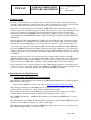
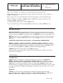
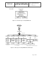
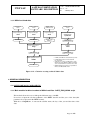
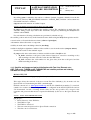
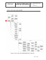
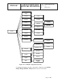
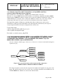
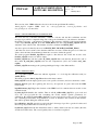
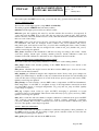
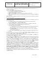
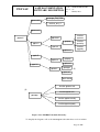
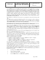
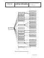
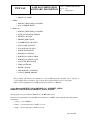
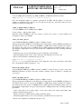
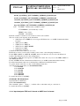
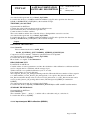
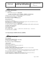
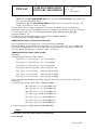
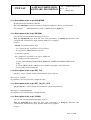
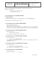
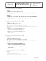
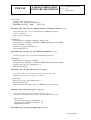
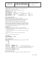
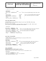
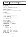
3.4. DIRECT-READOUT OF NOAA SATELLITE DATA.
For NOAA direct readout, the interface to AAPP is at “Level 0”, i.e. the HRPT reception system is
assumed to have the capability of receiving the NOAA HRPT data stream, as defined by NOAA [1].
AAPP_RUN_NOAA is the main module of the AAPP chain, for TOVS/ATOVS sounders and
AVHRR radiometer on the NOAA satellites. It links up the different steps, ingest and pre-processing.
www.space-track.org
NOAA Satellite
Get Two Lines
get_tle
TBUS bulletin
OR
Ingest bulletin
tbusing
Two Lines element
Ingest bulletin
tleing
HRPT
User ground station
tbus_noaaXX.index
clock
error_noaaXX.txt
tle_noaaXX.index
OR
HRPT file
Take informations from the HRPT file
hrptidf
Decommutation
decommutation
Check/correct the scan line datation
chk1btime
HIRS AAPP l1a
AMSUA AAPP l1a
AMSUB or MHS
AAPP l1a
Orbit number
Get the orbit number
sdh2orbnum
Creation of the satpos file
satpost or satpostle
satpos_NOAAXX_date.txt
AVHRR AAPP l1a*
See the following figure
Figure 3-1 : First steps for treating NOAA data
Page 16 /202
AAPP DOCUMENTATION
SOFTWARE DESCRIPTION
NWP SAF
Doc ID : NWPSAF-MF-UD-002
Version : 7.6
Date
: 06 May 2015
satpos_NOAAXX_date.txt
HIRS AAPP l1a
AMSUA AAPP l1a
Compute calibration
coefficients/navigation/localisation
hirscl
or
hirscl_algoV4
hirs_historic_file_manage
hcalcb1_algoV4
HIRS AAPP l1b
AMSUB or MHS
AAPP l1a
AVHRR AAPP l1a*
Compute calibration
coefficients/navigation
/localisation
amsuacl
Compute calibration
coefficients/navigation
/localisation
amsubcl
or
mhscl
Compute calibration
coefficients/navigation
/localisation
avhrcl
AMSUA AAPP l1b
AMSUB or MHS
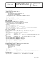
AAPP l1b
AVHRR AAPP l1b*
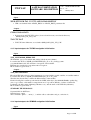
See the following figure
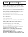
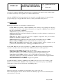
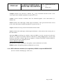
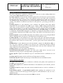
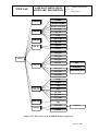
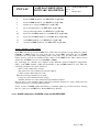
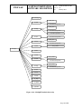
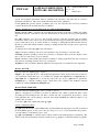
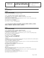
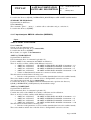
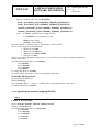
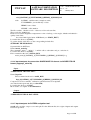
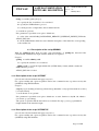
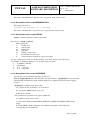
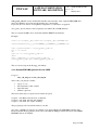
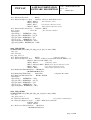
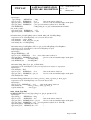
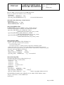
Figure 3-2 : Second steps for treating NOAA data
Page 17 /202
NWP SAF
AAPP DOCUMENTATION
SOFTWARE DESCRIPTION
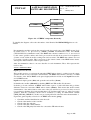
HIRS AAPP l1b
AMSUA AAPP l1b
AMSUB or MHS
AAPP l1b
Pre-processing step1:
atovin
Pre-processing step1:
atovin
Pre-processing step1:
atovin
HIRS AAPP l1c
AMSUA AAPP l1c
AMSUB/MHS **
AAPP l1c
Doc ID : NWPSAF-MF-UD-002
Version : 7.6
Date
: 06 May 2015
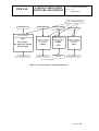
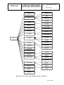
Pre-processing step2: ***
atovpp
AVHRR AAPP l1b*
HIRS AAPP l1d***
AVHRR mapping/Cloud mask: ****
avh2hirs
HIRS AAPP l1d****
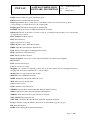
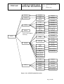
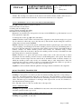
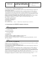
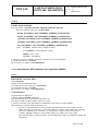
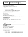
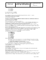
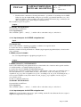
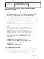
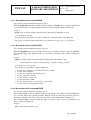
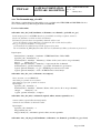
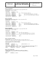
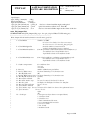
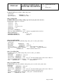
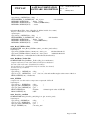
* In AAPP, the AVHRR file is named with the "hrpt" word.
** In AAPP, MHS l1c data are in a file named with
the "amsub" word.
*** In this figure, the creation of a HIRS l1d file is shown.
With the same chain, AMSUA l1d, MHS l1d or IASI l1d
can be created. But with no cloud mask for those data.
**** AVHRR mapping and cloud mask is only available for
HIRS, not for AMSUA, MHS or IASI.
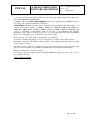
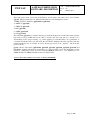
Figure 3-3 : Pre-processing steps for NOAA data
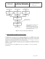
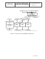
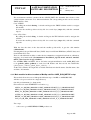
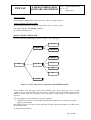
3.5. DIRECT-READOUT OF METOP SATELLITE DATA.
For METOP direct readout, the interface to AAPP is at “EPS Level 0”, i.e. the HRPT reception system
is assumed to have the capability of receiving the METOP AHRPT data stream and converting to EPS
level 0 format, as defined by EUMETSAT [25]. In this format the various instruments are delivered as
separate files, therefore there is no need for a decommutation task.
Software tools are supplied within the “metop-tools” section of AAPP to convert EPS level 0 format to
AAPP level 1a format. Calibration, navigation and pre-processing then proceed in the same way as for
the NOAA satellites.
For a general description of the METOP processing, see the AAPP v6 (or v7) Top Level Design
document [24]
Page 18 /202
AAPP DOCUMENTATION
SOFTWARE DESCRIPTION
NWP SAF
Doc ID : NWPSAF-MF-UD-002
Version : 7.6
Date
: 06 May 2015
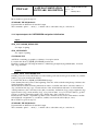
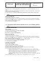
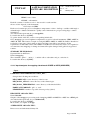
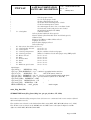
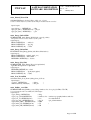
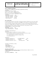
maia.usno.navy.mil
Once a month:
Navigation initialisation
Get the polar motion:
International Atomic Time (TAI)
Coordinated Universal Time (UTC)
Universal Time 1 (UT1)
get_tai_ut1_utc
tai_utc.dat
finals2000A.data
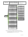
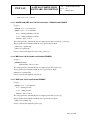
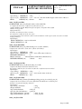
Figure 3-4 : Periodical step for treating METOP data
METOP Satellite
AHRPT
User ground station
HIRS PFS L0
AMSU-A PFS L0
MHS PFS L0
AVHRR PFS L0
ADMIN CCSDS
format
IASI PFS L0
See other
figure
Convert HIRS PFS L0
to HIRS AAPP l1a
format
decom-hirsmetop
Convert AMSU-A
PFS L0 to AMSU-A
AAPP l1a format
decom-amsuametop
Convert MHSPFS L0
to MHS AAPP l1a
format
decom-mhsmetop
Convert AVHRR PFS
L0 to HIRS AAPP l1a
format
decom-avhrrmetop
HIRS AAPP l1a
AMSUA AAPP l1a
MHS AAPP l1a
AVHRR AAPP l1a*
tai_utc.dat
Navigation initialisation
spming
spm_date_time.txt
finals2000A.data
spm_MXX.index
See the following figure
* In AAPP, the AVHRR file is named with the "hrpt" word
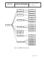
Figure 3-5 : First steps for treating METOP data (ATOVS part)
Page 19 /202
NWP SAF
AAPP DOCUMENTATION
SOFTWARE DESCRIPTION
finals2000A.data
tai_utc.dat
Doc ID : NWPSAF-MF-UD-002
Version : 7.6
Date
: 06 May 2015
spm_date_time.txt
spm_MXX.index
Creation of the satpos file
sateph
(calls ephe,
satpostle or satposspm)
satpos_MXX_date.txt
HIRS AAPP l1a
Calibration/navigation/localisation
hirscl
or
hirscl_algoV4
hirs_historic_file_manage
hcalcb1_algoV4
HIRS AAPP l1b
AMSUA AAPP l1a
MHS AAPP l1a
AVHRR AAPP l1a*
Calibration/navigation/lo
calisation
amsuacl
Calibration/navigation/lo
calisation
mhscl
Calibration/navigation/lo
calisation
avhrcl
AMSUA AAPP l1b
MHS AAPP l1b
AVHRR AAPP l1b*
See the following figure
ephe_MXX_date.txt
* In AAPP, the AVHRR file is named with the "hrpt" word
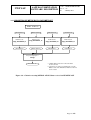
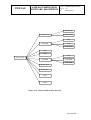
Figure 3-6 : Second steps for treating METOP data (ATOVS part)
Page 20 /202
NWP SAF
AAPP DOCUMENTATION
SOFTWARE DESCRIPTION
Doc ID : NWPSAF-MF-UD-002
Version : 7.6
Date
: 06 May 2015
METOP Satellite
AHRPT
For AVHRR, HIRS, AMSUA, MHS
See other figure
Convert AVHRR AAPP
l1b to AVHRR PFS
L1b format
aapp-eps_avhrrl1b
AVHRR PFS L1c
IASI PFS L0
IASI OPS-LRS
IASI PFS L1C
Convert IASI PFS L1c to IASI
AAPP l1c format
convert_iasi1c
AVHRR AAPP l1a*
IASI AAPP l1C
* In AAPP, the AVHRR file is named with the "hrpt" word
See the following figure
Figure 3-7 : First steps for treating METOP data (IASI part)
Page 21 /202
NWP SAF
AAPP DOCUMENTATION
SOFTWARE DESCRIPTION
HIRS AAPP l1b
AMSUA AAPP l1b
MHS AAPP l1b
Pre-processing step1:
atovin
Pre-processing step1:
atovin
Pre-processing step1:
atovin
HIRS AAPP l1c
AMSUA AAPP l1c
MHS AAPP l1c**
IASI_eig_encode.dat
Doc ID : NWPSAF-MF-UD-002
Version : 7.6
Date
: 06 May 2015
Pre-processing step2: *****
iasi_eigenvectors
IASI_eig_decode.dat
IASI_noise.dat
Pre-processing step2: ***
atovpp
IASI AAPP l1C
HIRS AAPP l1d***
AVHRR AAPP l1b*
AVHRR mapping/Cloud mask: ****
avh2hirs
HIRS AAPP l1d****
* In AAPP, the AVHRR file is named with the "hrpt" word.
** In AAPP, MHS l1c data are in a file named with the "amsub" word.
*** In this figure, the creation of a HIRS l1d file is shown. With the same
chain, AMSUA l1d, MHS l1d or IASI l1d can be created. But with no
cloud mask for those data.
**** AVHRR mapping and cloud mask is only available for HIRS, not for
AMSUA, MHS or IASI.
*****"iasi_eigenvectors" is called automatically by the atovpp script
Figure 3-8 : Pre-processing steps for METOP data
Page 22 /202
NWP SAF
AAPP DOCUMENTATION
SOFTWARE DESCRIPTION
Doc ID : NWPSAF-MF-UD-002
Version : 7.6
Date
: 06 May 2015
3.6. ACQUISITION OF METOP DATA VIA EUMETCAST
METOP - EUMETCast
HIRS BUFR l1c
BUFR decode:
aapp_decodebufr_1c
HIRS AAPP l1c
AMSUA BUFR l1b
BUFR decode:
aapp_decodebufr_1c
AMSUA AAPP l1c
MHS BUFR l1b
IASI BUFR l1b
BUFR decode:
aapp_decodebufr_1c
BUFR decode:
aapp_decodebufr_1c
MHS AAPP l1c*
IASI AAPP l1c
Pre-processing step2: **
atovpp
HIRS AAPP l1d**
* In AAPP, MHS l1c data are in a file named with
the "amsub" word.
** In this figure, the creation of a HIRS l1d file is shown.
With the same chain, AMSUA l1d, MHS l1d or IASI l1d
can be created.
Figure 3-9 : Chain for treating METOP -ATOVS data received via EUMETCAST
Page 23 /202
AAPP DOCUMENTATION
SOFTWARE DESCRIPTION
NWP SAF
Doc ID : NWPSAF-MF-UD-002
Version : 7.6
Date
: 06 May 2015
METOP - EUMETCAST
HIRS BUFR 1c
AVHRR PFS
BUFR decode:
aapp_decodebufr_1c
Convert to
AAPP format
HIRS AAPP l1c
AVHRR AAPP
Pre-processing
step2: atovpp
HIRS AAPP l1d
AAPP AVHRR mapping Cloud
mask: avh2hirs
HIRS AAPP l1d
Figure 3-10 : Chain for treating METOP –AVHRR - HIRS data received via
EUMETCAST
Page 24 /202
AAPP DOCUMENTATION
SOFTWARE DESCRIPTION
NWP SAF
Doc ID : NWPSAF-MF-UD-002
Version : 7.6
Date
: 06 May 2015
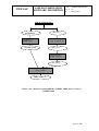
3.6.1. NOAA archived data
HIRS NOAA l1b
archive
AMSUA NOAA l1b
archive
AMSUB or MHS
NOAA l1b archive
AVHRR NOAA l1b
archive
Pre-processing step1:
atovin
Pre-processing step1:
atovin
Pre-processing step1:
atovin
Convert AVHRR NOAA l1b to
AVHRR AAPP l1b:
hrpt1b_noaa
HIRS AAPP l1c
AMSUA AAPP l1c
AMSUB or MHS
AAPP l1c**
AVHRR AAPP l1a*
Pre-processing step2: ***
atovpp
Calibration
avhrcl
HIRS AAPP l1d***
AVHRR AAPP l1b*
AVHRR mapping/Cloud mask: ****
avh2hirs
HIRS AAPP l1d****
* In AAPP, the AVHRR file is named with the "hrpt" word.
** In AAPP, MHS l1c data are in a file named with
the "amsub" word.
*** In this figure, the creation of a HIRS l1d file is shown.
With the same chain, AMSUA l1d, MHS l1d or IASI l1d
can be created. But with no cloud mask for those data.
**** AVHRR mapping and cloud mask is only available for
HIRS, not for AMSUA, MHS or IASI.
Figure 3-11 : Chain for treating archived NOAA data
4. GENERAL DESCRIPTION
4.1. SOFTWARE MAIN COMPONENTS
4.1.1. Main module for direct-readout of NOAA satellites. AAPP_RUN_NOAA script
This module allows the user to link up the different steps of AAPP.
It receives as input the absolute pathname of the HRPT data file and the year of the data (this
parameter is not present in the HRPT format).
With the tool hrpidf.exe , it extracts the satellite name, the day of the year and the time of the
data.
Page 25 /202
NWP SAF
AAPP DOCUMENTATION
SOFTWARE DESCRIPTION
Doc ID : NWPSAF-MF-UD-002
Version : 7.6
Date
: 06 May 2015
The environment variables contained in the ATOVS_ENV7 file determine the selection of the
orbital bulletins and model. Two different bulletins and corresponding models can be selected:
TBUS and Two-Line.
Case of TBUS:
By calling the module tbusing , it checks and ingests the TBUS bulletins useful to navigate
the satellite.
It creates the satellite position-velocity file for several days (satpos file) with the command
satpost.
Case of Two-Line:
By calling the module tleing , it checks and ingests the TLE bulletins useful to navigate the
satellite.
It creates the satellite position-velocity file for several days (satpos file) with the command
satpostle.
With the date, the time of the data and the satellite position file, it gets the orbit number
(sdh2orbnum).
It distinguishes the pre-NOAA-K data (TOVS data) from NOAA-KLM data (ATOVS data) and
from NOAA-N,N’ data.
Then, it calls different modules to make the decommutation, navigation/localisation, calibration,
mapping, cloud mask tasks (decommutation, hirscl/hirscl_algoV4, msucl, amsuacl, amsubcl,
mhscl, avhrcl, atovin, atovpp, avh2hirs).
For AVHRR, HIRS and MSU, before and after navigation/calibration task, AAPP_RUN calls
tools (prhavh, prhirs, prhmsu) to write level 1B headers and first records into ASCII files
(phavh_before_calib.log, phavh_before_calib.log, …).
At the end, it renames all output files to include information in the file names: Satellite name, date
and time, orbit number.
4.1.2. Main module for direct-readout of MetOp satellite. AAPP_RUN_METOP script
This module allows the user to link up the different steps of AAPP or AAPP/OPS-LRS.
All files to be processed are in a single directory
One file per instrument (i.e. dump mode)
File names follow the EUMETSAT convention, e.g.
AMSA_xxx_00_M04_20020808181206Z_20020808195406Z_N_O_20020808201206Z
MHSx_xxx_00_M04_20020808181201Z_20020808195401Z_N_O_20020808201201Z
HIRS_xxx_00_M04_20020808181200Z_20020808195358Z_N_O_20020808201200Z
AVHR_xxx_00_M04_20020808181200Z_20020808182359Z_N_O_20020808201200Z
HKTM_xxx_00_M04_20020808181200Z_20020808195358Z_N_O_20020808201200Z
IASI_xxx_00_M04_20020808181200Z_20020808195358Z_N_O_20020808201200Z
Two steps:
-
a first one to get AMSU/HIRS/AVHRR products out
Page 26 /202
NWP SAF
-
AAPP DOCUMENTATION
SOFTWARE DESCRIPTION
Doc ID : NWPSAF-MF-UD-002
Version : 7.6
Date
: 06 May 2015
a second one to run IASI OPS-LRS and generate products on IASI grid OPS-LRS requires
AVHRR l1b. IASI OPS-LRS is not automatically included in the AAPP v7 distribution. It
must be requested by the user.
The environment variables contained in the ATOVS_ENV7 file determine the selection of the
orbital bulletins and model.
Case of TBUS:
By calling the module tbusing , it checks and ingests the TBUS bulletins useful to navigate
the satellite.
It creates the satellite position-velocity file for several days (satpos file) with the command
satpost.
Case of Two-Line:
By calling the module tleing , it checks and ingests the TLE bulletins useful to navigate the
satellite.
It creates the satellite position-velocity file for several days (satpos file) with the command
satpostle.
Case of spot:
By calling the module spming , it checks and ingests the spm bulletins useful to navigate the
satellite.
It creates the satellite position-velocity file for several days (satpos file) with the command
satposspm.
Note that spot bulletins are being phased out by EUMETSAT and will not be included in the
Admin Message for MetOp-B. Instead, the new Multi-Mission Administrative Message
(MMAM) will include TLEs for multiple MetOp and NOAA satellites.
With the date, the time of the data and the satellite position file, it gets the orbit number
(sdh2orbnum).
Optionally, get OBT/UTC correlation parameters from Admin message in HKTM file and
over-write VIADR in instrument files. (This step is not required if your station manufacturer has
properly implemented the OBT-UTC handling).
Then, it calls different modules:
. to convert in AAPP format l1b (decom-amsua-metop, decom-mhs-metop, decom-hirsmetop, decom-avhrr-metop
-
to make navigation/localisation, calibration (hirscl/hirscl_algoV4, msucl, amsuacl,
amsubcl, mhscl, avhrcl).
To make the preprocessing (atovin, atovpp, avh2hirs)
If OPS-LRS is present,
-
OPS-LRS is called.
-
the outfile is converted to AAPP 1C format
the preprocessing atovpp and avh2hirs are called
Page 27 /202
NWP SAF
AAPP DOCUMENTATION
SOFTWARE DESCRIPTION
Doc ID : NWPSAF-MF-UD-002
Version : 7.6
Date
: 06 May 2015
At the end, it renames all output files to include information in the file names: Satellite name, date
and time, orbit number.
4.1.3. Main module for FY1 imager data. AAPP_RUN_FY1 script
This module allows the user to extract and calibrate the five AVHRR-like channels of the MVISR
instrument on the Chinese FY-1D satellite.
The first step is to convert the input data to pseudo-NOAA format by calling convert_chrpt
script. the satellite identifier is checked. the default bulletin tle is maked.
Then the main script AAPP_RUN_NOAA is called with specific arguments.
AAPP_RUN_NOAA -C -i "AVHRR" -Y $YEAR -o $OUTDIR fy1.hrp
The level 1a file is re-named with “fy1-04” being replaced by “fy1d”. Finally the fy1cl script is
run, to create a level 1b file (AVHRR format).
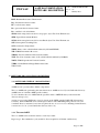
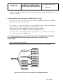
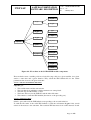
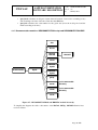
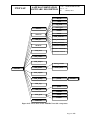
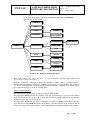
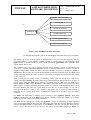
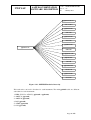
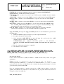
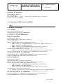
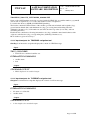
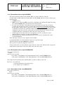
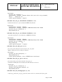
4.1.4. Satellite and image navigation initialisation: Ingest with TBUS bulletin,TBUSING
script, TBUSING.EXE and satellite position and velocity: SATPOST script,
SATPOST.EXE
Modules TBUSING, TBUSING.EXE
(See also reference manual pages: tbusing.1 , libtbus.3 , tbus.5 , clockerror.5 , libbrolyd.3)
tb_chk
tb_dc
tb_prn
brolyd
tb_ctrl
TBUSING
celem
tb_glpv
tb_wind
tb_sdc
clkerr_dc
clkdatnorm
clkerr_ctrl
clkvalnorm
clkerr_wind
Figure 4-1 : Flow chart on the components of the TBUSING module
Page 28 /202
NWP SAF
AAPP DOCUMENTATION
SOFTWARE DESCRIPTION
Doc ID : NWPSAF-MF-UD-002
Version : 7.6
Date
: 06 May 2015
These modules allow the ingest of TBUS bulletin(s). They can process one or several satellites
(option). The TBUS file name can be specified (option). By default all the tbus files which are
newer than the last update of the index files corresponding to the satellite list are ingested.
For each satellite, 2 historical files are created or updated:
• TBUS index file : relative to the TBUS orbital parameters. Each record contains epoch time,
quality, tbus filename
• clock error file : contains all the clock error information which has been validated
The TBUS epoch may be at any position in the historical files which means that an old TBUS can
be inserted in the files.
To insert new information :
• clock error and orbital parameter have to be extracted from TBUS resources bulletin.
• the user chooses files in relation to satellites to treat (input configuration).
• quality controls are made to check new orbit continuity compared to the preceding orbit (the
brolyd extrapolation model is used), and to compare clock errors with the preceding ones.
TASK 1 : INPUT PARAMETERS READING
tbusing gets :
• Home directory of the TBUS files and bulletin(s) name(s) which will be stored in the TBUS
index file.
• The list of satellites to be considered
• Historical file names
TASK 2: INITIALISATION
It opens the TBUS bulletin(s).
TASK 3: TBUS BULLETIN DECOMMUTATION AND VALIDATION TESTS
For each satellite:
It opens (or creates if files do not exist) the historical index file and the clock drift error file.
It calls different subroutines :
tb_dc to decode the part IV of the TBUS bulletin to extract orbital parameters and to check that
extracted parameters are in the authorised value area.
tb_ctrl to check the orbital parameters continuity (to compare them with the last valid parameters
registered in the historical file), using the brolyd extrapolation model. The new TBUS file is
declared OK if the errors are less than 6 km/day. The tests with the last preceding valid tbus are
done only if the time difference is less than 7 days.
tb_wind to write the valid TBUS information record at the end of the historical file.
clkerr_dc to decode the clock error values stored in the plain language message at the end of the
TBUS file Part IV and to check that extracted clock errors are in the authorised values area.
clkerr_ctrl to check the decoded clock values by comparing them to the preceding historical
values.
clkerr_wind to write the valid clock error information record at the end of the clock drift data
file, and on the standard input.
At the end, tbusing closes the different files.
Page 29 /202
NWP SAF
AAPP DOCUMENTATION
SOFTWARE DESCRIPTION
Doc ID : NWPSAF-MF-UD-002
Version : 7.6
Date
: 06 May 2015
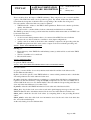
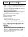
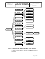
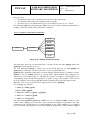
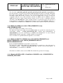
Modules SATPOST ,SATPOST.EXE
(See also reference manual pages: satpost.1 , satpos.5 , libbrolyd.3)
tb_gnv
tb_chk
tb_glpv
tb_prn
tb_dc
brolyd
gstatc
tb_fnode
SATPOS
tb_forb
tb_satpos
celem
pvitodgrw
trackang
sungrw
sunsat
Figure 4-2 : Flow chart on the SATPOST module components.
These modules create a satellite position-velocity file (satpos file) for a given satellite, for a given
station, a start time and a given duration. They search the TBUS bulletin file for the orbital
parameters time closest to the given start time.
TASK 1: INPUT PARAMETERS READING
satpost gets :
• The satellite name and the station name
• The start time from which the orbital parameters are extrapolated.
• The time step and the number of days.
• The home directory for the TBUS files and the index file name.
• The criteria to search the TBUS bulletin (the nearest or the preceding one).
TASK 2: INITIALISATION
It finds, opens and reads the TBUS bulletin corresponding to the research criterion.
To find the file name of the valid TBUS bulletin, it calls the subroutune tb_gnv if the search
criteria is the nearest to the start time. The searched TBUS date must be in a time interval. It calls
tb_glpv if the search criterion is the last preceding valid TBUS filename from the index file. The
index file is supposed to be chronological
tb_dc decodes the part IV of the TBUS bulletin to extract orbital parameters and to check that
extracted parameters are in the authorised value area.
Page 30 /202
NWP SAF
AAPP DOCUMENTATION
SOFTWARE DESCRIPTION
Doc ID : NWPSAF-MF-UD-002
Version : 7.6
Date
: 06 May 2015
By calling gstatc, it initialises the station coordinates (latitude, longitude, altitude) from the file
stations.txt (directory DIR_STATIONS defined in ~/ATOVS_ENV) and then converts them into
Greenwich cartesian coordinates.
satpost returns information on standard output.
TASK 3: POSITION CALCULATIONS FOR ALL THE STEPS
tb_satpos does this task. It calculates the satellite position. The calculations are made since the
start date during several days with a time increment. It begins by initialising the brolyd model
with the current TBUS.
For each time the following calculations are performed (calculation loop):
the satellite position and velocity in the inertial reference frame using the brolyd extrapolation model.
conversion into a Greenwich reference frame (celem and pvitodgrw).
orbit number deduced from the z component
visibility from the station including refraction (trackang)
satellite in daylight or nighttime conditions if the satellite is seen from the station (sungrw, sunsat).
It writes the results on the standard output.
tb_satpos calls others subroutines to initiate variables useful to brolyd model:
•
tb_fnode calculates nodal period (time interval between 2 successive ascending nodes)
and ascending node time of the first orbit after the TBUS date.
•
tb_forb calculates the orbit number for the given date (from the nodal period and the
initial ascending node time).
4.1.5. Satellite and image navigation initialization with Two Line Element sets:
GET_TLE script, TLEING script, TLEING.EXE and satellite position and velocity:
SATPOSTLE script, SATPOSTLE.EXE.
Module GET_TLE
(See also reference manual pages: get_tle.1 tleing.1 , tle.5 )
This script allows the retrieval of the most recent Two-Line bulletin(s) (tle) from the web site
Space-Track or Celestrak using the GNU command wget.
Default connection is to www.space-track.org and the file identification number 7 is retreived
(number for weather satellites). All parameters are configured in the ATOVS_ENV file and are
self documented. At time of writing default values are the only possible ones, except for the
username and password that must be requested individually by the user to the Space-Track web
site.
TASK 1 : INPUT PARAMETERS READING
get_tle gets :
• Home directory of the TLE files.
• The URL for login
• The URL for download
• The user name and password for Space-Track connection.
• The time-out for connections.
Page 31 /202
NWP SAF
AAPP DOCUMENTATION
SOFTWARE DESCRIPTION
Doc ID : NWPSAF-MF-UD-002
Version : 7.6
Date
: 06 May 2015
TASK 2: LOGIN
Sends a wget commands that logins and store cookies in a temporary file.
TASK 3: DOWNLOAD AND STORE
Sends a wget command to download selected file, and load login cookies
Uncompress the file with gunzip command
Store file in TLE directory
Modules TLEING, TLEING.EXE
(See also reference manual pages: tleing.1 , libtle.3 , tle.5 , libsgp.3f)
tle_chk
tle_dc
tle_prn
tle_glpv
tle_sdc
tleing
tle_ctrl
sgp4
sdp4
tle_wind
Figure 4-3 : Flow chart on the components of the TLEING module
These modules allow the ingest of Two-Line bulletin(s) (tle). They can process one or several
satellites (option). The Two-Line file name can be specified (option). By default all the tle files
which are newer than the last update of the index files corresponding to the satellite list are
ingested.
For each satellite, one historical file is created or updated:
• TLE index file: relative to the TLE orbital parameters. Each record contains epoch time,
quality, tbus filename
The TLE epoch may be at any position in the historical files which means that an old TLE can be
inserted in the files.
To insert new information:
Page 32 /202
NWP SAF
•
•
•
AAPP DOCUMENTATION
SOFTWARE DESCRIPTION
Doc ID : NWPSAF-MF-UD-002
Version : 7.6
Date
: 06 May 2015
orbital parameters have to be extracted from TLE resources bulletin.
the user chooses files depending on which to satellites are to be processed(input
configuration).
quality controls are made to check new orbit continuity compared to the preceding orbit (the
sgp4 extrapolation model is used).
TASK 1 : INPUT PARAMETERS READING
tleing gets:
• Home directory of the TLE files and bulletin(s) name(s) which will be stored in the TLE
index file.
• The list of satellites to be considered
• Historical file names
TASK 2: INITIALISATION
It opens the TLE bulletin(s).
TASK 3: TLE BULLETIN DECOMMUTATION AND VALIDATION TESTS
For each satellite:
It opens (or creates if files do not exist) the historical index file.
It calls different subroutines :
tle_dc to decode the TLE bulletin to extract orbital parameters and to check that extracted
parameters are in the authorised value area.
tle_ctrl to check the orbital parameters continuity (to compare them with the last valid parameters
registered in the historical file), using the sgp extrapolation model. The new TLE file is declared
OK if the errors are less than 6 km/day. The tests with the last preceding valid tbus are done only
if the time difference is less than 7 days.
tle_wind to write the valid TLE information record at the end of the historical file.
At the end, tleing closes the different files
Modules SATPOSTLE, SATPOSTLE.EXE
(See also reference manual pages: satpostle.1 , satpos.5 , libsgp.3f)
Page 33 /202
NWP SAF
AAPP DOCUMENTATION
SOFTWARE DESCRIPTION
Doc ID : NWPSAF-MF-UD-002
Version : 7.6
Date
: 06 May 2015
tle_chk
tle_dc
tle_prn
tle_glpv
sgp4
sdp4
tle_gnv
tle_fnode
satpostle
gstatc
tle_forb
pvtemegrw
tle_satpos
trackang
sungrw
sunsat
Figure 4-4 : Flow chart on the SATPOSTLE module components.
These modules create a satellite position-velocity file (satpos file) for a given satellite, for a given
station, a start time and a given duration. They search the TLE bulletin file for the orbital
parameters time closest to the given start time.
TASK 1: INPUT PARAMETERS READING
satpostle gets :
• The satellite name and the station name
• The start time from which the orbital parameters are extrapolated.
• The time step and the number of days.
• The home directory for the TLE files and the index file name.
• The criteria to search the TLE bulletin (the nearest or the preceding one).
TASK 2: INITIALISATION
It finds, opens and reads the TLE bulletin corresponding to the research criterion.
To find the file name of the valid TLE bulletin, it calls the subroutune tle_gnv if the search
criteria is the nearest to the start time. The searched TLE date must be in a time interval. It calls
Page 34 /202
NWP SAF
AAPP DOCUMENTATION
SOFTWARE DESCRIPTION
Doc ID : NWPSAF-MF-UD-002
Version : 7.6
Date
: 06 May 2015
tle_glpv if the search criterion is the last preceding valid TLE filename from the index file. The
index file is supposed to be chronological
tle_dc decodes the TLE bulletin to extract orbital parameters and to check that extracted
parameters are in the authorised value area.
By calling gstatc, it initialises the station coordinates (latitude, longitude, altitude) from the file
stations.txt (directory DIR_STATIONS defined in ~/ATOVS_ENV) and then converts them into
Greenwich Cartesian coordinates.
satpostle returns information on standard output.
TASK 3: POSITION CALCULATIONS FOR ALL THE STEPS
tle_satpos does this task. It calculates the satellite position. The calculations are made since the
start date during several days with a time increment. It begins by initialising the sgp4/sdp4 model
with the current TLE.
For each time the following calculations are performed (calculation loop):
the satellite position and velocity in the inertial reference frame using the sgp4/sdp4 extrapolation
model.
conversion into a Greenwich reference frame (pvtemegrw).
orbit number deduced from the z component
visibility from the station including refraction (trackang)
satellite in daylight or nighttime conditions if the satellite is seen from the station (sungrw, sunsat).
It writes the results on the standard output.
tle_satpos calls others subroutines to initiate variables useful to sgp model:
•
tle_fnode calculates nodal period (time interval between 2 successive ascending nodes)
and ascending node time of the first orbit after the TLE date.
•
tle_forb calculates the orbit number for the given date (from the nodal period and the
initial ascending node time).
4.1.6. Satellite and image navigation initialization with SPOT-5 element sets (METOP
only): GET_TAI_UT1_UTC script, SPMING script, ADMIN-MAIN.EXE, ADMINMESSAGES.EXE and satellite position and velocity: SATPOSSPM script,
SATPOSSPM.EXE.
Module GET_TAI_UT1_UTC
That module is requested by celestial reference frame conversions for SPOT-5 model. The
conversion needs to know the values of the Polar motion and the conversions between Temps
Atomique International (TAI), Coordinated Universal Time (UTC), Universal Time 1 (UT1). The
script access the server maia.usno.navy.mil and retrieves two files tai-utc.dat and
finals2000A.data, by default they are stored in the $DIR_NAVIGATION/orb_elem directory.
All necessary variables are defined in the ATOVS_ENV. The polar motion and UT1-UTC data
are predictable and the file finals2000A.data contains predictions for several weeks or months.
The user should run this command once a month.
Page 35 /202
NWP SAF
AAPP DOCUMENTATION
SOFTWARE DESCRIPTION
Doc ID : NWPSAF-MF-UD-002
Version : 7.6
Date
: 06 May 2015
Modules SPMING, SPMING.PL, SPMING.EXE, ADMIN-MAIN.EXE, ADMINMESSAGES.EXE
Figure 4-5 : Flow chart on the components of the SPMING module
These modules allow the ingest of SPOT-5 bulletin(s) (spm). SPOT-5 bulletins are available
through METOP Administrative messages, these messages are part of the AHRPT data flow. But
note that SPOT-5 bulletins are being phased out by EUMETSAT, and will not be available in the
new Multi-Mission Administrative Messages (MMAM). These two modules can process only one
Page 36 /202
NWP SAF
AAPP DOCUMENTATION
SOFTWARE DESCRIPTION
Doc ID : NWPSAF-MF-UD-002
Version : 7.6
Date
: 06 May 2015
satellite. The SPOT-5 file name can be specified (option). By default all the (spm) files which are
newer than the last update of the index files corresponding to the satellite list are ingested.
For each satellite, one historical file is created or updated:
1. SPM index file: relative to the SPOT-5 orbital parameters. Each record contains epoch time,
quality, spot-5 filename
The SPM epoch may be at any position in the historical files which means that an old SPM can be
inserted in the files.
To insert new information:
2. orbital parameters have to be calculated from previous SPM resources bulletin.
3. the user chooses files depending on which to satellites are to be processed (input
configuration).
4. quality controls are made to check new orbit continuity compared to the preceding orbit (the
spm extrapolation model is used).
TASK 1 : DECODING ADMIN MESSAGES
This done by admin-main.exe; this program extracts SPOT bulletin from binary ADMIN
messages and outputs an ASCII representation.
TASK 2 : INPUT PARAMETERS READING
spming gets:
5. Home directory of the SPM files and bulletin(s) name(s) which will be stored in the SPM
index file.
6. Satellite to be considered
7. Historical file names
TASK 3: INITIALISATION
It opens the SPM bulletin(s).
TASK 4: SPM BULLETIN VALIDATION TESTS
Reads the index file and for each record that contains a negative orbit number it:
- calls spm_dc to decode the SPM bulletin, extract orbital parameters and check that extracted
parameters are in the authorised value area.
- calls spm_ctrl to check the orbital parameters continuity (to compare them with the last valid
parameters registered in the historical file), using the spm extrapolation model. The new SPM file
is declared OK if the errors are less than 6 km/day. The tests with the last preceding valid SPM
are done only if the time difference is less than 7 days. It returns the calculated orbit number at
epoch.
For all records it writes to the output file the updated record (extrapolation error, flag, orbit) or
input record depending on initial test.
TASK 5: EXTRACT ASCII MESSAGES FROM ADMIN MESSAGE
admin-messages.exe extracts the ASCII buffer of the ADMIN message and stores it in
$DIR_NAVIGATION/messages/messages_satid_YYYYMMDD.txt.
Page 37 /202
NWP SAF
AAPP DOCUMENTATION
SOFTWARE DESCRIPTION
Doc ID : NWPSAF-MF-UD-002
Version : 7.6
Date
: 06 May 2015
Modules SATPOSSPM, SATPOSSPM.EXE
Figure 4-6 : Flow chart on the SATPOSSPM module components.
Page 38 /202
NWP SAF
AAPP DOCUMENTATION
SOFTWARE DESCRIPTION
Doc ID : NWPSAF-MF-UD-002
Version : 7.6
Date
: 06 May 2015
These modules create a satellite position-velocity file (satpos file) for a given satellite, for a given
station, a start time and a given duration. They search the SPM bulletin file for the orbital
parameters time closest to the given start time.
TASK 1: INPUT PARAMETERS READING
satposspm gets :
• The satellite name and the station name
• The start time from which the orbital parameters are extrapolated.
• The time step and the number of days.
• The home directory for the SPM files and the index file name.
• The criteria to search the SPM bulletin (the nearest or the preceding one).
TASK 2: INITIALISATION
It finds, opens and reads the SPM bulletin corresponding to the research criterion.
To find the file name of the valid SPM bulletin, it calls the subroutine spm_gbul. The searched
SPM date must be in a time interval. The index file is supposed to be chronological. The
subroutines also calls spm_dc in order to decode the SPM bulletin. Spm_gbul stores all valid
bulletins in a time period.
By calling gstatc, it initialises the station coordinates (latitude, longitude, altitude) from the file
stations.txt (directory DIR_STATIONS defined in ~/ATOVS_ENV) and then converts them into
Greenwich Cartesian coordinates.
Routines read_pm_ut1utc and read_tai_utc returns the values of polar motion and time
difference between UTC, UT1 and TAI.
satposspm returns information on standard output.
TASK 3: POSITION CALCULATIONS FOR ALL THE STEPS
spm_satpos does this task. It calculates the satellite position. The calculations are made since the
start date during several days with a time increment. It begins by initialising the spm model with
the current SPM.
For each time the following calculations are performed (calculation loop):
•
check if the current bulletin is the best available for the time step.
•
If time step day changes, update polar motion and UTC conversion by calling
read_pm_ut1utc and read_tai_utc
the satellite position and velocity in the inertial reference frame using the spm_model
extrapolation model and the conversion subroutine osc_to_rec from osculating to rectangular
elements.
conversion into a Greenwich reference frame (pvj2000grw).
orbit number deduced from the z component
visibility from the station including refraction (trackang)
satellite in daylight or nighttime conditions if the satellite is seen from the station (sungrw,
sunsat).
It writes the results on the standard output.
spm_satpos calls others subroutines to initiate variables useful to spm model:
Page 39 /202
NWP SAF
AAPP DOCUMENTATION
SOFTWARE DESCRIPTION
Doc ID : NWPSAF-MF-UD-002
Version : 7.6
Date
: 06 May 2015
•
spm_fnode calculates nodal period (time interval between 2 successive ascending nodes)
and ascending node time of the first orbit after the SPM date.
•
spm_forb calculates the orbit number for the given date (from the nodal period and the
initial ascending node time).
4.1.7. Decommutation modules: DECOMMUTATION script and DECOMMUTATION.EXE.
dcin
dcsetu
function
chksatid
rdnoaaid
cktime
function
hrpdat
decommutation
hrptdc
function
hrptim
genqc
atovdc
see its own module
hierarchy
avhrdc
see its own module
hierarchy
dcexit
Figure 4-7 : DECOMMUTATION and HRPTDC module hierarchy.
To simplify the diagram, the calls to subroutines of the libf7ml , libf7tp , libf7nl1b libraries have
not been written.
Page 40 /202
NWP SAF
AAPP DOCUMENTATION
SOFTWARE DESCRIPTION
Doc ID : NWPSAF-MF-UD-002
Version : 7.6
Date
: 06 May 2015
o tig e t
d c s ge t
d c s in
d c s o ut
d c s hd u
fu nc tio n
l1 bs c id
h irge t
h irhd u
fu nc tio n
l1 b s c n a m
h irou t
hirs d c
m s u o ut
m s u hd u
a n a ge t
m s u dc
a tov dc
a m s uq c
am sget
a m s ua _ lin e c he c k
am ast
a m s hd u
a m a n a g_ o u t
a m bs t
m hs s t
a m s o ut
am sadc
a m s b dc
g e tm f
m hs d c
tiptim
tip q c
fu nc tion
o rdtiid
Figure 4-8 : ATOVDC components hierarchy.
To simplify the diagram, the calls to subroutines or functions of the libf7ml,
libf7tp, libf7gp, libf7nl1b , libf7cp libraries have not been written.
Page 41 /202
NWP SAF
AAPP DOCUMENTATION
SOFTWARE DESCRIPTION
Doc ID : NWPSAF-MF-UD-002
Version : 7.6
Date
: 06 May 2015
avtelm
avhrdc
avtipg
avhdtw
avhhdu
Figure 4-9 : AVHRDC components hierarchy.
To simplify the diagram, calls to the subroutines of the libraries like libf7ml, libf7gp have not be
written
Decommutation modules perform the extraction task for several parts of the HRPT stream (level
0) which have to be processed by avhrdc (AVHRR decommutation task) and atovdc
(TOVS/ATOVS decommutation task). The HRPT minor frames, numbered 1 to 3, are received
by the center- specific routines and can be processed in real time from several local acquisition
systems or read off-line from files coming from various centers. The HRPT minor frames are read
by a center- specific routine. This is necessary as the extract format of the HRPT minor frames
will depend on the hardware of the reception station.
After decommutation, there is one raw data file for each instrument. Those files represent the
level 1a data.
TASK 1: INITIALISATION
hrptdc performs this task.
This module receives as an input the unpacked HRPT minor frame(s) coming from the center
specific module closely connected to the hardware. The HRPT minor frame is an array of 11090
words made of the 10 bits HRPT words placed right justified in 16 bits words. hrptdc detects the
end of HRPT stream.
hrptdc reads input options (dcin) and opens the various files (dcsetu).
It identifies the satellite (chksatid) by checking HRPT and TIP satellite Id coherence.
It checks good start condition: an HRPT minor frame equal to 1, with valid time and good time
difference between consecutive HRPT minor frames (cktime). This means that under normal
circumstances a few minor frames at the start of the pass will not be processed, as they are used
for consistency checking. If it is known that there is no bad data at the start (e.g. when processing
granules) then the consistency check can be disabled by setting an environment variable
(SKIP_DECOM_CHECK=Y); in this case processing will start at the first minor frame number 1.
It performs general quality controls for one HRPT minor frame (genqc).
• Check the satellite identification at the first call
• Check of the number of the scan line
• Check of the date and time
• Check of the minor frame number
• Check of the TIP parity bits in the five consecutive TIP minor frames
Page 42 /202
NWP SAF
AAPP DOCUMENTATION
SOFTWARE DESCRIPTION
Doc ID : NWPSAF-MF-UD-002
Version : 7.6
Date
: 06 May 2015
Check parity bits in every TIP word for ATOVDC and flag the relevant bits in the quality
indicator
It computes the number of possible missing HRPT minor frames (= the number of possible
missing AVHRR scan line).
•
It calls the routine atovdc that will extract HIRS, AMSU-A/B (or MSU if TOVS, MHS if
NOAA-N,N’) and DCS data from TIP/AMSU minor frames. TIP/AMSU minor frames are
embedded in 3 consecutive HRPT minor frames. The first one contains 5 TIP minor frames, the
second one contains 'backfill' (dummy data) and the third one contains 5 AMSU minor frames.
For pre-NOAA-K satellite, each of the 3 consecutive HRPT minor frames contains the same 5
TIP minor frames.
It calls the routine avhrdc that extracts AVHRR data from one HRPT minor frame.
TASK 2: TOVS/ATOVS AND DCS DECOMMUTATION TASK
The module atovdc performs this task called by the hrptdc.
It receives as input from hrptdc:
• 5 TIP or AMSU minor frames (extracted from one HRPT minor frame).
• HRPT minor frame number (1,2 or 3)
• The number of the HRPT minor frame in the orbit (= AVHRR scan line in the orbit).
• The number of missing HRPT minor frame
• The satellite identifcation
• Various dates and times
• …
It determines if minor frames contain pre-NOAA-K data or not from the satellite ID, at the first
call.
It removes 2 least significant parity bits: TIP/AMSU words are 8 bits words, HRPT words are 10
bits words.
It determines if minor frames contain TIP, AMSU or backfill data.
If TIP minor frame (=if HRPT minor frame number equal to 1) :
• Extracts TIP minor frame counter and TIP major frame counter (getmf)
• Extracts time from TIP word in TIP minor frame number 0 (tiptim)
• Performs quality controls (tipqc)
• Calls the routine hirget that extracts HIRS/3 words
• If pre-NOAA-K data, calls the routine otiget that extracts HIRS/2 and MSU words
• Calls the routine dcsget that extracts DCS words
• Calls the routine hirout when the HIRS scan line is full
• If pre-NOAA-K data, calls the routine msuout when the MSU scan line is full
• Calls the routine dcsout when DCS data is full
If AMSU minor frame (=if HRPT minor frame number equal to 3) :
• Extracts minor frame counter to find good conditions to start
• Performs quality controls (amsuqc)
• Calls the routine amsget that extracts AMSU-A1/A2 and B (or MHS) words
• Calls the routine amsout when the AMSU scan line is full
If HRPT minor frames are missing, it fills arrays.
If TIP minor frame, atovdc extracts analog housekeeping telemetry data (anaget).
Page 43 /202
NWP SAF
AAPP DOCUMENTATION
SOFTWARE DESCRIPTION
Doc ID : NWPSAF-MF-UD-002
Version : 7.6
Date
: 06 May 2015
Finally, on completion of the atovdc module, separated HIRS/3 (or HIRS/4), AMSU-A, AMSUB (or MHS) & DCS level 1a files are obtained, or HIRS/2, MSU and DCS level 1a files in case of
pre-NOAA-K TIP data.
TASK 3: AVHRR DECOMMUTATION TASK
The module avhrdc performs this task, called by hrptdc.
It receives as input from hrptdc:
• an array of HRPT minor frames (in actual fact this array contains only one HRPT minor
frame in this version of AAPP).
• Miscellaneous variables : The minor frame number of the orbit (=the number of the
AVHRR scan line), the number of missing HRPT minor frames (=the number of missing
AVHRR scan lines), the HRPT minor frame number(=1 or 2 or 3), the satellite
identification, the orbit number, dates and times,…
It fills the variables for one record of the AVHRR output file (=for one AVHRR scan line) :
• Variables of the scan line information part.
• Date and time
• Quality indicators from genqc results.
• Variables of the telemetry data part (avtelm).
• Variables of the video data.
• Variables of the TIP header data part and the CPU A and B telemetry part from TIP data
(avtipg).
It calls the routine avhdtw which writes the direct access AVHRR output file, corresponding to
the given scan line number.
It updates the header variables in the avh1bdh common (avhhdu.).
TASK 4: CORRECT SCAN LINE DATATION FOR LEVEL 1 B FILES
(See also reference manual pages chk1btime.1)
The module chk1btime checks and corrects the scan line datation for a given level 1a file that has
been processed by atovdc. chk1btime is called for HIRS, MSU, AMSU-A and AMSU-B
instruments. The AVHRR (hrpt.l1b file) does not require chk1btime correction.
Note that chk1btime can not work for NOAA level 1b file because NOAA files have missing
records. AAPP ones do not have missing records because AAPP fills records when scan lines are
missing.
The error in atovdc is to use the same date information for all instuments. The AAPP developers
have preferred to correct the files than fixing the bug in the decommutation step.
This program is dependant on 1B format structure.
It trusts the time indicated in the 1st scan line of the file.
4.1.8. EPS level 0 to AAPP level 1a conversion for METOP: DECOM-AMSUA-METOP
script and AMSUA-MAIN.EXE, DECOM-MHS-METOP script and MHS-MAIN.EXE,
DECOM-AMSUA-HIRS script and HIRS-MAIN.EXE, DECOM-AVHRR-METOP script and
AVHRR-MAIN.EXE.
These modules are to be found in the “metop-tools” directories. Each script takes two arguments:
the name of the Level 0 input file and the name of the level 1a output file.
Page 44 /202
AAPP DOCUMENTATION
SOFTWARE DESCRIPTION
NWP SAF
Doc ID : NWPSAF-MF-UD-002
Version : 7.6
Date
: 06 May 2015
There is a script and a binary program associated with each instrument.
Instrument
Script
Binary
HIRS
decom-hirs-metop
hirs-main.exe
AVHRR
decom-avhrr-metop
avhrr-main.exe
MHS
decom-mhs-metop
mhs-main.exe
AMSUA
decom-amsua-metop
amsua-main.exe
In order to process level 0 data, each main program implements five routines; for instance, hirsmain.c contains the definition of the following routines:
•
hirs_l1b_open
•
hirs_l1b_write_header
•
hirs_l1b_write_record
•
hirs_l1b_write_dummy
•
hirs_l1b_close
Each of these routines call the Fortran routines of AAPP; we list here what those routines are for
each instrument:
AVHRR
HIRS
MHS
AMSUA
l1b_open
Fortran open
Fortran open
Fortran open
Fortran open
l1b_write_header
avhhdw
hrshdw
mhshdw
amahdw
l1b_write_record
avhrdc
hirout
amsout
amsout
l1b_write_dummy
avhrdc
hirout
amsout
amsout
l1b_close
Fortran close
Fortran close
Fortran close
Fortran close
In common-main.c, the main loop for level 0 processing is implemented (subroutine
common_loop). This processing loop is used for AVHRR, HIRS and MHS. AMSUA data
processing requires its own loop, because of the two sub-instruments AMSUA1 and AMSUA2.
The processing loop reads level 0 data using the library libeps_metopl0 and passes instrument
data packets to AAPP using the five routines described above.
CCSDS packets are decoded using libccsds, and UTC time is computed from OBT using
libobtutc.
AAPP libf7tp and libsatid are used too.
Page 45 /202
NWP SAF
AAPP DOCUMENTATION
SOFTWARE DESCRIPTION
Doc ID : NWPSAF-MF-UD-002
Version : 7.6
Date
: 06 May 2015
4.1.9. Convert chrpt (FY1c and FY1d satellites) ) to hrpt (NOAA satellites):
convert_chrpt script and convert_chrpt.exe
These modules are to be found in the “AAPP/src/decommutation/bin” directories.
The aim is to convert CHRPT data from FY1 satellite to a form that is compatible with NOAA HRPT,
taking just the AVHRR-like channels. Output can be fed into the AAPP decommutation routine. Some
dummy TIP data are created in order to satisfy the AAPP error checks. Also some of the variables
(target temps and warm cal counts) are stored in non-standard locations in the output file.
The input frame length is 27740 bytes at the Met Office. May be different for other receiver
manufacturers. This represents 22180 10-bit words when unpacked. Alternatively, the script can
accept an input file that has already been unpacked into 16-bit words.
Usage of the script:
convert_chrpt [-u] infile outfile day_of_year
with –u option for unpacked input
For details, see inside convert_chrpt.F file
4.1.10. Image navigation modules: HIRSCL script and HIRSCL.EXE, HIRSCL_ALGOV4
script and HIRSCL_ALGOV4.EXE, MSUCL script and MSUCL.exe, AMSUACL script
and AMSUACL.EXE, AMSUBCL script and AMSUBCL.EXE, MHSCL script and
MHSCL.EXE, AVHRCL script and AVHRCL.EXE.
(See also reference manual pages: libnavnoaa.3, libnavtool.3, libsatid.3 and detailed navigation
equations in [17] )
def_att
calatt
xclsetu
clkerr_get
ctimang
sp_read
intposvel
XXXCL
x_loc
nav_1blin
earthloc
cartgeo
hd1bnav
Figure 4-10 : general flow chart on the location module components :
HIRSCL/MSUCL/AMSUnCL/MHSCL/AVHRCL
The image navigation converts the line and pixel into latitude and longitude for any pixel of the
image. The task needs files: the level 1a file of the considered instrument, the SATPOS file, the
CLOCK ERROR file. Modules are called for the different tasks.
Page 46 /202
NWP SAF
AAPP DOCUMENTATION
SOFTWARE DESCRIPTION
Doc ID : NWPSAF-MF-UD-002
Version : 7.6
Date
: 06 May 2015
TASK 1 : INITIALISATION
hclin/hclin_algoV4/mclin/amaclin/ambclin/mhsclin/avhclin get logical units of the files.
hclsetu/mclsetu/amasetu/amsubsetu/mhssetu/avhsetu :
• Open and read the level 1a file.
• Open the SATPOS file.
• sp_read reads the SATPOS file and tests if the input starting time is included into the
SATPOS file, and if the satellite Id and memory are correct.
• If input attitude is missing, call def_att that returns the default attitudes value. Those values
depend on satellite (see satid file).
• Open the CLOCK ERROR file.
• Call calatt that calculates the attitude error matrix for small yaw, roll and pitch angles. This
matrix is allowed to change the reference: local orbital coordinates (Rv) (x: satellite vertical,
y: normal to x and z, z: normal to x and to velocity vector) / coordinates (Rs) linked to the
spacecraft structure.
• Get clock error data if the level 1a has not already been taken into account in level 1a
(clkerr_get)
• Initialise navigation parameters.
TASK 2: CALCULATION OF THE IMAGE NAVIGATION PARAMETERS
h_loc/m_loc/ama_loc/amb_loc/mhs_loc check if the clock error has already been applied. If not
applied, the time and clock flag control of every line of data are modified and updated for level
1b. They call the routine nav_l1blin.
nav_1blin computes the navigation variables of the level 1b, for one scanning line and for one
instrument number. It calls the following routines and functions: genattid, lptoviewvect,
intposvel, snagre, earthpix. All information on default attitude, misalignment and description of
instruments scanning functions is stored in a satellite identification file (see satid.5 libsatid.3)
genscid and genattid returns the nominal attitude mode of the satellite. The different attitude
modes that can be considered are:
local normal pointing mode
yaw steering mode
geocentric mode
lptoviewvect converts the line and pixel numbers into the viewed vector smRS in the spacecraft
fixed reference frame Rs. (see [17] §4) This routines takes into account the scanning geometry of
the instrument.
intposvel interpolates (a 3 order polynomial interpolation) the satellite position and (relative)
velocity in Greenwich reference frame in the SATPOS file, for a given pixel time. This time is
included into a [t2,t3] interval of which position and velocity are referenced into SATPOS. These
2 points are used as reference for the polynomial coefficients calculation. The orbit number is
also determined for a given pixel. For ATOVS sounders, satellite position is recalculated for
every pixel of each scan line. On the contrary, for AVHRR image data (HRPT, GAC), position is
computed only for each scan line (assuming that the scanning of a line is instantaneous compared
to the satellite velocity).
snagre calculates the conversion matrix between Earth fixed Greenwich reference frame Rg and
nominal attitude reference frame Ra.
Page 47 /202
NWP SAF
AAPP DOCUMENTATION
SOFTWARE DESCRIPTION
Doc ID : NWPSAF-MF-UD-002
Version : 7.6
Date
: 06 May 2015
earthpix calculates the cartesian coordinates smRG in the Greenwich reference frame of the
viewed pixel smRS detailled explaination is given in [17] § 5.
cartlalo converts cartesian coordinates smRS into latitude-longitude on the earth surface (i.e.
altitude = 0)
zenazi calculates the zenith angle, azimut angle and distance of the spacecraft from the viewed
point on the earth surface detailled explaination is given in [17] § 6.
sungrw calculates the sun position in Greenwich reference frame
zenazi calculates the zenith angle, azimut angle and distance of the sun from the viewed point on
the earth surface.
After nav_1blin sets bit flags for variables of the level 1B file, does the conversions for the level
1B units. It computes the satellite altitude (in km*10) by calling cartgeog that converts (with
iterations) cartesian coordinates (Rg) into geographic coordinates (lat/lon/alt). Satellite altitude is
determined from the last computed position.
TASK 3: RESULTS UPDATING
h_loc updates navigation parameters and quality controls within the level 1b file.
hd1bnav updates navigation parameters within the level 1b file.
4.1.11. HIRS calibration modules (first algorithm): HIRSCL script and HIRSCL.EXE
(See also reference manual pages: libhrscal.3)
Page 48 /202
NWP SAF
AAPP DOCUMENTATION
SOFTWARE DESCRIPTION
hclin
Doc ID : NWPSAF-MF-UD-002
Version : 7.6
Date
: 06 May 2015
def_att
calatt
hclsetu
clkerr_get
sp_read
h_loc
nav_1blin
hd1bnav
h_cinit
h_instrtest
h_scanpos
hirscl
h_cntmn
h_calibcoeffile
h_testcoeffile
gp_x16
h_linecount
h_orderch
h_limit
h_iwttmp
h_cntstat
h_iwtrad
h_prtstat
h_interslop
h_linlin
h_prtsum
h_orderch
h_gtmean
gp_bse
h_upcommon1
gp_bcl
h_orderch
h_upcommon2
h_stat
hl1bwrt
gp_bse
gp_bcl
xiqj
hclexit
Figure 4-11 : Flow chart on the HIRSCL module components.
Page 49 /202
NWP SAF
AAPP DOCUMENTATION
SOFTWARE DESCRIPTION
Doc ID : NWPSAF-MF-UD-002
Version : 7.6
Date
: 06 May 2015
To simplify the diagram, the calls to subroutines of the libf7ml library have not
been written
This task requires HIRS level 1a, calcoef.dat and testcoef.dat resource files.
TASK 1: INITIALISATION
The user chooses his input options (script hirscl and hclin).
The main program is hirscl that calls many routines:
hclin reads the input options (tests some options coherence) and stores them into a table.
hclsetu opens the log/debug file hirscl.log if requested. It opens and reads the HIRS level 1a file
(the data are ranged in commons hrs1bhd (include hrs1bhd.h, header), hrs1bdts (include
hrs1bdts, data)).
h_cinit identifies the satellite. Then it calls h_calibcoeffile to open, read and close the calcoef.dat
file containing the useful satellite specific parameters for calibration. The data are ranged in
common hrs_clcf (include cinit.h). h_cinit by calling h_testcoeffile, opens, reads and closes the
testcoef.dat file containing useful values and parameters for tests. The data are ranged in the
common hrs_tstcf (include cinit.h). h_cinit opens the statistic file (if requested). A control quality
parameter array is initialised and will be modified by the tests performed during the calibration
processing. The satellite is identified.
h_instrtest checks the instrument status to define which scan line are usable (the first and the last
usable lines). The control quality parameters array is updated.
TASK 2: CALIBRATION COEFFICIENTS CALCULATION
The result of this task is a calibration coefficient array (calibcoef) for each sounding channel and
each scan line. HIRSCL calls many routines:
h_scanpos, for each scan line of each channel, checks the 56 encoder positions (quality bit 31 is
checked), and keeps the numbers of lines of the calibration cycles (space lines array: splintab and
internal warm target array: iwtlintab). h_scanpos checks if the calibration cycle is full or not and
sets up the variable calib (number of calibration cycle full). If calib equals zero, processing goes
directly to the task 3.
h_cntmn, for each calibration cycle of the orbit (for each space and internal warm target lines
registered during an orbit) and for each channel, filters numerical counts (CN) and computes the
CN mean. Those values are stored in arrays : spcntmn (space) and iwtcntmn (internal warm
target).
h_iwttmp, for each calibration cycle, calculates the internal warm target (IWT) temperature. It
computes the mean of a sample of PRT reading from the internal warm target scan line and from
a specified number of scan lines before the IWT scan line and another specified number of scan
lines after the IWT scan line. h_iwttmp tests the difference between the maximum PRT readings
value and the minimum one which must be inferior to a limit before being used in the mean
calculation. PRT readings means are converted to temperatures. The final IWT temperature is
computed by averaging the temperature from the 4 individual active PRTs (array iwttmp). The
quality control parameters array is updated.
h_iwtrad converts the IWT temperature (array iwtrad) (using the Planck function, applying
bands correction) for each channel and each calibration cycle.
h_interslop for each calibration cycle and each channel, computes gain G and offset I (residual
radiance equivalent to the space background noise viewed through the instrument channel) (array
calibcoef0). The coefficients of the visible channel are not measured in flight. A third coefficient
Page 50 /202
NWP SAF
AAPP DOCUMENTATION
SOFTWARE DESCRIPTION
Doc ID : NWPSAF-MF-UD-002
Version : 7.6
Date
: 06 May 2015
(order 2) is also designed for the calculation in addition to G and I. It is equal to zero for the
moment and so it is not yet used.
h_linlin for each channel and each Earth viewing scan line, computes the (G,I) pairs (array
calibcoef) by linear interpolation between 2 pairs of coefficients (G,I) calculated for 2
consecutive calibration cycles. For Earth viewing registered before the first calibration cycle there
is no interpolation, coefficients of the first calibration cycle are directly applied. For Earth
viewing registered after the last calibration cycle there is no interpolation, coefficients of the last
calibration cycle are directly applied. The quality control parameters array is updated.
h_gtmean for each channel, computes the mean (array calibcoefmn) and the standard deviation
(array calibcoefstd) of the coefficients (G,I). The header is updated in the level1b file.
TASK 3: RESULTS UPDATING
The result of this task is an update of calibration coefficients, and quality control parameters in
the HIRS level 1b resource file. According to input options, statistics results are stored into the
file monhirs.txt, and the log/debug file is updated.
h_upcommon1 or h_upcommon2 finish updating the parameters in the commons hrs1bhd, and
hrs1bdts (h_upcommon2 is called when there is no calibration).
h_stat computes final statistic of the HIRS calibration and writes the results into the statistic file,
and then closes the file (according to input options).
hl1bwrt updates header and data in the HIRS level1b file.
hclexit close the log/debug file and the HIRS level1b file.
4.1.12. HIRS calibration modules ( algorithm version 4): HCALCB1_ALGOV4 script and
HCALCB1_ALGOV4.EXE, HIRSCL_ALGOV4 script and HIRSCL_ALGOV4.EXE
Page 51 /202
NWP SAF
AAPP DOCUMENTATION
SOFTWARE DESCRIPTION
hc lin_ a lgo V 4
h c ls e tu _ a lgoV 4
Doc ID : NWPSAF-MF-UD-002
Version : 7.6
Date
: 06 May 2015
byte s w a p1 b
de f_ a tt
hg e tl1 b e le m e n t_ a lg oV 4
c a la tt
h_ loc
c lk e rr_ ge t
hd1 b na v
s p _ re a d
h_ c init_ a lgoV 4
na v _ 1 blin
h_ re a db 1 s lope _ a lg oV 4
h _ ins trte s t_ a lgoV 4
h_ s c a npo s _ a lgoV 4
h _ c a libc oe ffile _ a lgoV 4
h _ te s tc o e ffile _ a lg oV 4
h _ iw ttm p _ a lg oV 4
h _ line c oun t_ a lg oV 4
h _ iw tra d _ a lgoV 4
h _ prts ta t_ a lgo V 4
h_ c n tm n _ a lg oV 4
h_ o rd e rc h_ a lgo V 4
h_ B B inte rs lop_ a lgo V 4
h_ lim it_ a lg oV 4
h_ B B s lopc o ntrol_ a lgoV 4
h _ c nts ta t_ a lg oV 4
hirs c l_ a lg oV 4
h _ pa rtia l_ s up e rs w a th_ a lgo V 4
h_ m e d ia n _ a lg oV 4
h _ s lope _ a lg oV 4
h_ s s te m p_ a lgo V 4
h_ _ in te rc e p t_ a lgo V 4
h _ _ w rite _ h is to _ a lg oV 4
h_ _ g tb1 m e a n_ a lgo V 4
h_ u pc o m m o n1 _ a lgo V 4
h_ u pc o m m o n2 _ a lgo V 4
hl1 bw rt_ a lgo V 4
hc le x it_ a lg oV 4
Figure 4-12 : Flow chart on the HIRSCL_ALGOV4 module components.
To simplify the diagram, the calls to subroutines or functions of the libf7ml,
libsatid, libf7gp, libf7tp libraries have not been written
Page 52 /202
NWP SAF
AAPP DOCUMENTATION
SOFTWARE DESCRIPTION
Doc ID : NWPSAF-MF-UD-002
Version : 7.6
Date
: 06 May 2015
This version of the HIRS calibration doesn’t work for the pre-NOAA-K satellites.
hirscl_algoV4 requires HIRS
hirs_b1aslope.txt resource files.
level
1a,
calcoef_algoV4.dat,
testcoef_algoV4.dat
and
TASK 1: CREATE THE HIRS_B1ASLOPE.TXT FILE
The user chooses a reference date/time, a number of hours and the B1 coefficients and the
average slopes will be computed using data of the period defined by [ (the reference date/time –
the number of hours) – (the reference date/time)]. The reference date/time is the input arguments
of the script hcalcb1_algoV4. Note that AAPP_RUN calls the script hcalcb1_algoV4 with the
date/time of the current orbit. The number of hours is defined in ATOVS_ENV.
An other option is defined by the user in ATOVS_ENV: HCALIB_B1ASLOP_FLAG
(=0 if the user doesn’t want to have the time taken into account to define the period; =1 if the user
want to have the time (hours/minutes) taken into account to define the period).
The main program hcalcb1_algoV4.exe requires a hirs historic file. If the file doesn’t exist,
hcalcb1_algoV4 creates it, it will be empty.
hcalcb1_algoV4.exe calls the routine h_calcb1_algoV4 that reads the hirs_historic file (call to
the routine h_read_histo_algoV4) and does the computations (call to the routines moy_rms,
reglin).
hcalcb1_algoV4.exe manages the openings/writings/closings of the different files.
TASK 2: INITIALISATION
The script hirscl_algoV4 must run with the argument “–c” for doing the calibration task (see
AAPP_RUN).
The main program is hirscl_algoV4.exe that calls many routines:
hclin_algoV4 reads the input options (tests some options coherence) and stores them into a table.
hclsetu_algoV4 opens the log/debug file hirscl.log if requested. It opens and reads the HIRS
level 1a file.
hgetl1belement_algoV4 gets the elements of the HIRS level 1b commons that are useful for the
calibration task.
h_cinit_algoV4 identifies the satellite. Then it calls h_calibcoeffile_algoV4 to open, read and
close the calcoef_algoV4.dat file containing the useful satellite specific parameters for
calibration. By calling h_testcoeffile_algoV4, it opens, reads and closes the testcoef_algoV4.dat
file containing useful values and parameters for tests. It initializes the elements in the includes
that will be updated during the calibration task.
h_readb1slope_algoV4 opens/closes and reads the 'b1/average slope' file to get the b1 values and
the average slopes that will be used in the process.
h_instrtest_algoV4 checks the instrument status to define which scan line are usable (the first
and the last usable lines). The control quality array of scan lines is updated.
Page 53 /202
NWP SAF
AAPP DOCUMENTATION
SOFTWARE DESCRIPTION
Doc ID : NWPSAF-MF-UD-002
Version : 7.6
Date
: 06 May 2015
TASK 3: CALIBRATION COEFFICIENTS CALCULATION
The result of this task is a calibration coefficient array (calibcoef) for each sounding channel and
each scan line. hirscl_algoV4 calls many routines:
h_scanpos_algoV4, for each scan line, checks the quality bit 31, the 56 encoder positions and the
line counts. It keeps the numbers of lines of the calibration cycles (space lines array: splintab and
internal warm target array: iwtlintab). It also checks if the calibration cycle is full or not, checks if
one calibration cycle and the previous one are well separated by 40 scan lines, and sets up the
variable calib (number of calibration cycle full). If calib equals zero, processing goes directly to
the task 3.
h_iwttmp_algoV4, for each calibration cycle, calculates the internal warm target (IWT)
temperature: For each individual active PRT, it gets a sample of PRT readings from the internal
warm target scan line and from a specified number of scan lines before the IWT scan line and
another specified number of scan lines after the IWT scan line. h_iwttmp_algoV4 tests the PRT
readings before being used in the mean calculation. The mean of the PRT readings is converted
to temperature. The final IWT temperature is computed by averaging the temperatures from the 4
(5 for NOAA-N) individual active PRTs (array iwttmp). The quality control parameters array is
updated.
h_iwtrad_algoV4 converts the IWT temperatures into radiances (array iwtrad) (using the Planck
function, applying bands correction) for each channel and each calibration cycle.
h_cntmn_algoV4, for each calibration cycle of the orbit (for each space and internal warm target
lines registered during an orbit) and for each channel, filters numerical counts (CN) and computes
the CN mean. Those values are stored in arrays : spcntmn (space) and iwtcntmn (internal warm
target).
h_BBinterslop for each calibration cycle and each channel, computes the Black Body (BB) (or
raw) slope (auto coefficient 1), the BB (or raw) intercept (auto coefficient 0) and third coefficient
(auto coefficient 2) that is equal at zero for the moment (array calibcoef0). The coefficients of the
visible channel are not measured in flight.
h_BBslopcontrol controls the quality of the Bbslopes.
h_partial_superswath_algoV4 determines the calib cycles which will be involved in the
calculation of average slope for each superswath or partial superswath.
h_slope_algoV4 computes the calibration slopes for each channel and for each Earth view scan
line.
h_sttemp_algoV4 computes the Second Telescope Temperature for all lines.
h_intercept_algoV4 computes the intercept for each channel and for each Earth view line.
TASK 4: RESULTS UPDATING
The result of this task is an update of calibration coefficients, and quality control parameters in
the HIRS level 1b resource file.
h_write_histo_algoV4 stores calibration information of all calibration cycles in the hirs_ historic
ASCII file.
h_gtb1mean_algoV4 computes the means and the standard deviations of the b1 coefficients of
all the lines.
h_upcommon1_algoV4 or h_upcommon2_algoV4 finish updating the parameters in the
commons hrs1bhd, and hrs1bdts (h_upcommon2_algoV4 is called when there is only one or zero
calibration cycle).
hl1bwrt_algoV4 updates header and data in the HIRS level1b file.
Page 54 /202
NWP SAF
AAPP DOCUMENTATION
SOFTWARE DESCRIPTION
Doc ID : NWPSAF-MF-UD-002
Version : 7.6
Date
: 06 May 2015
hclexit_algoV4 closes the log/debug file and the HIRS level1b file.
4.1.13. MSU calibration modules: MSUCL script and MSUCL.EXE
(See also reference manual pages: libmsucal.3)
Page 55 /202
NWP SAF
AAPP DOCUMENTATION
SOFTWARE DESCRIPTION
mclin
mclsetu
Doc ID : NWPSAF-MF-UD-002
Version : 7.6
Date
: 06 May 2015
def_att
calatt
clkerr_get
m_loc
sp_read
hd1bnav
function
ord1bid
function
noascnam
m_cinit
m_calibcoeffile
m_testcoeffile
msucl
m_cntres
m_statsum
m_tgtmp
m_restmp
m_tgrad
m_plank
m_gfcounts
m_statsum
m_interslop
gp_bse
m_upcommon
gp_bcl
m_finalstat
xiqj
ml1bwrt
mclexit
Figure 4-13 : Flow chart on the MSUCL module components.
Page 56 /202
NWP SAF
AAPP DOCUMENTATION
SOFTWARE DESCRIPTION
Doc ID : NWPSAF-MF-UD-002
Version : 7.6
Date
: 06 May 2015
To simplify the diagram, the calls to subroutines of the libf7ml library have not
been written
This task requires MSU level 1a, calcoef.dat and testcoef.dat resource files .
TASK 1: INITIALISATION
The user chooses his input options (script msucl and mclin).
The main program is MSUCL that calls many routines:
mclin reads the input options (tests some options coherence) and stores them in a table.
mclsetu opens the log/debug file muscl.log if requested. It opens and reads the MSU level 1a file
msul1b (the data are ranged in commons msu1bhd (header), msu1bdts(data)).
m_cinit opens, reads and closes (m_calibcoeffile) the calcoef.dat file containing the useful
satellite specific parameters for calibration. The data are ranged in common msu_clcf (include
mcinit.h). m_cinit opens, reads and closes (m_testcoeffile) the testcoef.dat file containing useful
values and parameters for tests. The data are ranged in the common msu_tstcf (include mcinit.h).
m_cinit opens the statistic file (if requested). Two control quality parameters arrays are updated.
TASK 2: CALIBRATION COEFFICIENTS CALCULATION
The result of this task is two calibration coefficient arrays (slope, intercept) for each sounding
channel. msucl calls many routines:
m_tgtmp, for each scan line, computes target 1 temperature and target 2 temperature, which are
derived respectively from PRT 1A, 1B counts. Target 1 is viewed by channels 1 and 2, target 2 is
viewed by channels 3 and 4.
To convert PRT count to temperature requires two steps :
• Convert count to resistance (call m_cntres)
• Convert resistance to temperature (call m_restmp)
Conversion parameters are tabulated in the calcoef.dat file. m_tgtmp tests the low (tcallo) and
high (tcalli) values of the electronic reference points and sets a flag if values are out of limits. It
tests the temperature calculated with a reference. If the difference is higher than a threshold value,
then reference temperature is kept. Final temperature of each IWT is the mean of the two
associated PRT temperatures (arrays tg1 and tg2). Two control quality parameters arrays are
updated.
m_tgrad, for each scan line, converts the target 1 temperature into radiance for MSU channels 1
and 2 (array tgrad) (apply Planck function). Same for the target 2 temperature but for the MSU
channels 3 and 4.
m_gfcounts, for each scan line of each channel, applies the non linearity coefficients on the space
view output counts and the target output counts. m_gfcounts applies a filter (abs(count - averaged
count) compared to ( 2*standard deviation)) to eliminate counts out of limits. Different
parameters are stored in the statistic file (if requested). Array 2 of quality control parameters is
updated.
m_interslop, for each calibration cycle and each channel, computes the gain G and the offset I
(residual radiance equivalent to the space background noise viewed through the instrument
channel). The coefficients used afterwards (arrays slope and intercept), are averaged pairs (G,I)
coming from the calculation of the mean of the (G,I) values associated to each scan line and each
channel during an orbit.
Page 57 /202
NWP SAF
AAPP DOCUMENTATION
SOFTWARE DESCRIPTION
Doc ID : NWPSAF-MF-UD-002
Version : 7.6
Date
: 06 May 2015
TASK 3: RESULTS UPDATING
The result of this task is an update of the calibration coefficients and the quality control
parameters in the MSU level 1b resource file. According to input options, statistics results are
stored into the file monmsu.txt, and a log/debug file is updated.
m_upcommon updates the commons msu1bhd and msu1bdts.
m_finalstat computes the final statistic of the MSU calibration and writes the results into the
statistic file, and then closes the file (according to input options).
ml1bwrt updates header and data in the MSU level 1b file.
mclexit close the log/debug file and the MSU level 1b file.
4.1.14. AMSU-A calibration modules : AMSUACL script and AMSUACL.EXE.
Page 58 /202
NWP SAF
AAPP DOCUMENTATION
SOFTWARE DESCRIPTION
amaclin
Doc ID : NWPSAF-MF-UD-002
Version : 7.6
Date
: 06 May 2015
def_att
calatt
amasetu
sp_read
clkerr_get
ama_loc
amahdr
hd1bnav
amadtr
ama_initcl
function
ord1bid
ama_status
function
noascnam
amsuacl
ama_antpos
ama_smpmn
ama_iwttmp
prtchk
amedian
ama_avg
ama_cal
plank
amahdw
amadtr
ama_updt
amadtw
amaclexit
function
ord1bid
Figure 4-14 : Flow chart on the AMSUCL module components.
To simplify the diagram, the calls to subroutines of the libf7ml library have not
been written
Page 59 /202
NWP SAF
AAPP DOCUMENTATION
SOFTWARE DESCRIPTION
Doc ID : NWPSAF-MF-UD-002
Version : 7.6
Date
: 06 May 2015
This task requires the AMSU-A level 1a, amsua_clcoefs.dat and amsua_clparams.dat resource
files.
TASK 1: INITIALISATION
The user chooses his input options (script amsuacl and amaclin).
The main program is AMSUACL that calls many routines:
amaclin reads the input options and stores them in a table.
amasetu opens the log/debug file amsuacl.log and the statistic file monamsua.txt (if requested). It
opens and reads the AMSUA level 1a file (the data are ranged in commons ama_1bhd (include
ama1b.h, header), and scan (include amascn.h, data). amasetu checks the satellite Id and data, and
then set some control flags.
ama_initcl opens, reads and closes the amsua_clparams.dat file containing the useful parameters
for calibration. The data are arranged in the common ama_clcoef (include ama_cinit.h).
ama_initcl opens, reads and closes the amsua_clcoefs.dat file containing the values of the
secondary calibration coefficients. The data are arranged in the common ama_tstcf (include
ama_cinit.h). Quality control flags are updated.
ama_status determines if the instrument is OK and sets flags according to the results : checks
scan lines quality, checks space viewing antenna positions, checks calibration counts and
channels. If not OK, calibration coefficients are not computed for the bad scan line, but will be
replaced by secondary coefficients (amsua_clcoefs.dat).
TASK 2: CALIBRATION COEFFICIENTS CALCULATION
The results of this task is the primary calibration coefficient for each sounding channel.
ama_antpos checks if the antenna pointing of the AMSU Earth view is not outside of the
specified threshold.
ama_smpmn gets CN samples and computes the mean. For each channel and each scan line,
these averaged values are stored in the arrays spmean (space) and itmean (ITW). Quality control
flags are updated.
ama_iwttmp, for each scan line, converts PRT counts to temperature for IWT and instruments.
Final temperature of each IWT is a weighted average of the temperatures extracted from their
associated PRT. Arrays of averaged temperatures targ_temp and inst_temp are filled. Quality
control flags are updated.
ama_avg computes mean counts for space and IWT. Averaging is performed on several
consecutive lines for each channel. These mean values fill arrays spavg (space) and itavg (IWT).
Quality control flags are updated.
ama_cal, for each line and each channel, computes calibration coefficients from space and IWT
data: performs temperature/radiance conversion, deduces primary calibration coefficients
(a0,a1,a2). Primary and secondary coefficients (u0,u1,u2) are stored in the commons ama_1bhd
and scan. The quality control flags are updated.
TASK 3 : RESULTS UPDATING
The result of this task is an update of calibration coefficients and quality control parameters, in
the AMSU-A level 1b resource file.
According to input options, statistics results are stored into the stat file and a log/debug file is
updated.
ama_updt updates header and data in the AMSU-A level 1b.
Page 60 /202
NWP SAF
AAPP DOCUMENTATION
SOFTWARE DESCRIPTION
Doc ID : NWPSAF-MF-UD-002
Version : 7.6
Date
: 06 May 2015
amaclexit closes the log/debug file and the AMSU-A level 1b file
.
4.1.15. AMSU-B calibration modules: AMSUBCL script and AMSUBCL.EXE.
Page 61 /202
NWP SAF
AAPP DOCUMENTATION
SOFTWARE DESCRIPTION
Doc ID : NWPSAF-MF-UD-002
Version : 7.6
Date
: 06 May 2015
def_att
calatt
sp_read
ambclin
clkerr_get
ambhdr
ambsetu
ambdtr
amb_readcorr
amb_loc
amb_testnewbias
amb_calcorrect
hd1bnav
function ord1bid
function noascnam
amb_initcl
function noascid
amb_status
amb_antpos
moon_position
amsubcl
amb_moon
moon_amsu
amb_smpmn
amb_iwttmp
prtchk
amedian
amb_avg
plank
amb_cal
ambhdw
amb_updt
ambdtr
ambdtw
ambclexit
Figure 4-15 : Flow chart on the AMSUBCL module components.
Page 62 /202
NWP SAF
AAPP DOCUMENTATION
SOFTWARE DESCRIPTION
Doc ID : NWPSAF-MF-UD-002
Version : 7.6
Date
: 06 May 2015
To simplify the diagram, the calls to subroutines of the libf7ml library have not
been written
This task requires the AMSU-B level 1a, amsub_clcoefs.dat, amsub_clparams.dat and
amsub_bias.dat resource files .
TASK 1: INITIALISATION
The user chooses his input options (script amsubcl and ambclin).
The main program is AMSUBCL that calls many routines:
ambclin reads the input options and stores them in a table.
ambsetu opens the log/debug file amsubcl.log and the statistic file monamsub.txt (if requested). It
opens and reads the AMSU-B level 1a file (the data are ranged in commons amb_1bhd (include
amb1b.h, header), and scan (include ambscn.h, data). ambsetu calls amb_readcorr to read bias
correction tables and stores in level 1b header. It calls amb_testnewbias to detect presence of
AMSU-B anomalous bias due to moding of STX-1 transmitter. Then, it calls amb_calcorrect to
correct AMSU-B space and target counts for bias errors. ambsetu checks the satellite Id and data,
and then sets some control flags.
amb_initcl opens, reads and closes the amsub_clparams.dat file containing the useful parameters
for calibration. The data are arranged in the common amb_clcoef (include amb_cinit.h).
amb_initcl opens, reads and closes the amsub_clcoefs.dat file containing the values of the
secondary calibration coefficients. The data are arranged in the common amb_tstcf (include
amb_cinit.h). Quality control flags are updated.
amb_status determines if the instrument is OK and sets flags according to the results : checks
scan lines quality, checks space viewing antenna positions, checks calibration counts and
channels. If not OK, calibration coefficients are not computed for the bad scan line, but will be
replaced by secondary coefficients (amsub_clcoefs.dat).
TASK 2 : CALIBRATION COEFFICIENTS CALCULATION
The result of this task is the primary calibration coefficient for each sounding channel.
amb_antpos checks if the antenna pointing of the AMSU Earth view is not outside of the
specified threshold.
amb_moon calculates the angles between the Moon and the AMSU-B space views for all scans,
based on astronomical formulae.
amb_smpmn gets calibration samples and computes the mean. If any of the space samples are
within a pre-defined angle to the Moon, they are excluded from the mean. For each channel and
each scan line, these averaged values are stored in the arrays spmean (space) and itmean (ITW).
Quality control flags are updated.
amb_iwttmp, for each scan line, converts PRT counts to temperature for IWT and instruments.
Final temperature of each IWT is a weighted average of the temperatures extracted from their
associated PRT. Arrays of averaged temperatures targ_temp and inst_temp are filled. Quality
control flags are updated.
amb_avg computes mean counts for space and IWT. Averaging is performed on several
consecutive lines for each channel. These mean values fill arrays spavg (space) and itavg (IWT).
Quality control flags are updated.
amb_cal, for each line and each channel, computes calibration coefficients from space and IWT
data: performs temperature/radiance conversion, deduces primary calibration coefficients
Page 63 /202
NWP SAF
AAPP DOCUMENTATION
SOFTWARE DESCRIPTION
Doc ID : NWPSAF-MF-UD-002
Version : 7.6
Date
: 06 May 2015
(a0,a1,a2). Primary and secondary coefficients (u0,u1,u2) are stored in the commons amb_1bhd
and scan. The quality control flags are updated.
TASK 3 : RESULTS UPDATING
The result of this task is an update of calibration coefficients and quality control parameters, in
the AMSU-B level 1b resource file. According to input options, statistics results are stored into
the stat file and a log/debug file is updated.
amb_updt updates header and data in the AMSU-B level 1b.
ambclexit closes the log/debug file and the AMSU-B level 1b file.
4.1.16. MHS calibration modules: MHSCL script and MHSCL.EXE.
Page 64 /202
NWP SAF
AAPP DOCUMENTATION
SOFTWARE DESCRIPTION
mhsclin
Doc ID : NWPSAF-MF-UD-002
Version : 7.6
Date
: 06 May 2015
def_att
calatt
mhssetu
sp_read
clkerr_get
mhs_loc
mhshdr
mhsdtr
hd1bnav
function noascid
function ord1bid
mhs_initcl
function noascnam
mhs_status
moon_position
mhs_antpos
moon_amsu
mhscl
mhs_moon
mhs_smpmn
prtchk
amedian
mhs_iwttmp
mhs_avg
plank
mhs_cal
mhshdw
mhs_updt
mhsdtr
mhsdtw
mhsclexit
Figure 4-16 : Flow chart on the AMSUBCL and MHSCL module components.
To simplify the diagram, the calls to subroutines of the libf7ml library have not
been written
Page 65 /202
NWP SAF
AAPP DOCUMENTATION
SOFTWARE DESCRIPTION
Doc ID : NWPSAF-MF-UD-002
Version : 7.6
Date
: 06 May 2015
This task requires the MHS level 1a, mhs_clcoefs.dat and, mhs_clparams.dat resource files.
TASK 1: INITIALISATION
The user chooses his input options (script mhscl and mhsclin).
The main program is MHSCL that calls many routines:
mhsclin reads the input options and stores them in a table.
mhssetu opens the log/debug file mhscl.log and the statistic file monmhs.txt (if requested). It
opens and reads the MHS level 1a file (the data are ranged in commons mhs_1bhd (include
mhs1b.h, header), and scan (include mhsscn.h, data). mhssetu checks the satellite Id and data, and
then sets some control flags.
mhs_initcl opens, reads and closes the mhs_clparams.dat file containing the useful parameters
for calibration. The data are arranged in the common mhs_clcoef (include mhs_cinit.h).
mhs_initcl opens, reads and closes the mhs_clcoefs.dat file containing the values of the secondary
calibration coefficients. The data are arranged in the common mhs_tstcf (include mhs_cinit.h).
Quality control flags are updated.
mhs_status determines if the instrument is OK and sets flags according to the results : checks
scan lines quality, checks space viewing antenna positions, checks calibration counts and
channels. If not OK, calibration coefficients are not computed for the bad scan line.
TASK 2 : CALIBRATION COEFFICIENTS CALCULATION
The result of this task is the primary calibration coefficient for each sounding channel.
mhs_antpos checks if the antenna pointing of the AMSU Earth view is not outside of the
specified threshold.
mhs_moon calculates the angles between the Moon and the MHS space views for all scans,
based on astronomical formulae.
mhs_smpmn gets calibration samples and computes the mean. If any of the space samples are
within a pre-defined angle to the Moon, they are excluded from the mean. For each channel and
each scan line, these averaged values are stored in the arrays spmean (space) and itmean (ITW).
Quality control flags are updated.
mhs_iwttmp, for each scan line, converts PRT counts to temperature for IWT and instruments.
Final temperature of each IWT is a weighted average of the temperatures extracted from their
associated PRT. Arrays of averaged temperatures targ_temp and inst_temp are filled. Quality
control flags are updated.
mhs_avg computes mean counts for space and IWT. Averaging is performed on several
consecutive lines for each channel. These mean values fill arrays spavg (space) and itavg (IWT).
Quality control flags are updated.
mhs_cal, for each line and each channel, computes calibration coefficients from space and IWT
data: performs temperature/radiance conversion, deduces primary calibration coefficients
(a0,a1,a2). Primary and secondary coefficients (u0,u1,u2) are stored in the commons mhs_1bhd
and scan. The quality control flags are updated.
TASK 3 : RESULTS UPDATING
The result of this task is an update of calibration coefficients and quality control parameters, in
the MHS level 1b resource file. According to input options, statistics results are stored into the
stat file and a log/debug file is updated.
mhs_updt updates header and data in the MHS level 1b.
Page 66 /202
NWP SAF
AAPP DOCUMENTATION
SOFTWARE DESCRIPTION
Doc ID : NWPSAF-MF-UD-002
Version : 7.6
Date
: 06 May 2015
mhsclexit closes the log/debug file and the MHS level 1b file.
4.1.17. AVHRR calibration module: AVHRCL script and AVHRCL.EXE.
(See also the reference manual pages libavhcal.3)
Page 67 /202
NWP SAF
AAPP DOCUMENTATION
SOFTWARE DESCRIPTION
avhclin
Doc ID : NWPSAF-MF-UD-002
Version : 7.6
Date
: 06 May 2015
avhhdr
function ord1bid
function noascnam
avh_cpar
avhsetu
def_att
calatt
clkerr_get
avh_get
avh_qc
sp_read
gp_bse
chkch3
avh_iprt
avh_gprt
avhrcl
avh_gvie
filter
avh_filt
avh_cal
avh_poly
avh_ccof
avh_sum
function avh_bcor
avh_lico
avhdtr
avhdtw
xiqj
avh_put
xijq
gp_sb16
gp_sb32
nav_1blin
avh_clst
xiqj
hd1bnav
avh_hdu
avhclex
avhhdw
Figure 4-17 : Flow chart on the AVHRCL module components.
Page 68 /202
NWP SAF
AAPP DOCUMENTATION
SOFTWARE DESCRIPTION
Doc ID : NWPSAF-MF-UD-002
Version : 7.6
Date
: 06 May 2015
To simplify the diagram, the calls to subroutines of the libf7ml library have not
been written
This task requires the AVHRR level 1a and avhcal.txt resource files.
TASK 1: INITIALISATION
The user chooses his input configuration (options). A statistic file is opened. Quality control flags
are set and will be modified all along the program performance.
avhclin reads the input options and stores them in a table.
avhsetu opens the statistic file monavhr.txt, opens and reads the AVHRR level 1a file (the data
are ranged in avh1b.h). Satellite Id is set. avhsetu opens, reads and closes the file avhcal.txt
containing the useful parameters for satellite specific calibration.
avh_get reads the AVHRR level 1a file (only the part needed by calibration) and stores the data
into memory.
avh_qc checks the quality of each AVHRR scan line from the file and flags the lines having bad
scan numbers inside the level 1b file. Bad line numbers are corrected. avh_qc gets the first
calibration sequence from the data.
TASK 2: CALIBRATION COEFFICIENTS CALCULATION
The result of this task is the calibration coefficients for each channel and each scan line.
avh_cal manages the main loop for AVHRR calibration :
• initialises thermistors PRT counts arrays (avh_iprt).
• for each calibration cycle, fills the count arrays for the 4 PRTs.
• fills the IWT count arrays and the space count arrays (avh_gvie).
• pass Gross and Sigma filters to eliminate noisy counts (avh_filt).
• computes coefficients for each AVHRR calibration cycle (converts mean PRT counts to
mean IWT temperature, computes target radiance and deduces (G,I) coefficients (avh_ccof)
and calibration coefficients (k1,k2,k3), and linearises (avh_lico) the coefficients for each
scan line.
TASK 3: RESULTS UPDATING
The result of this task is an update of the calibration coefficients in the AVHRR level 1a resource
file. Statistics results are stored into the file monavhr.txt.
avh_put updates data in the AVHRR level 1b file.
avh_clst finishes the statistic calculation relative to calibration, writes the results and closes the
statistics file.
avhclex updates header and closes the AVHRR level 1b file.
4.1.18. ATOVS sounders calibration: ATOVIN script and ATOVIN.EXE
Page 69 /202
NWP SAF
AAPP DOCUMENTATION
SOFTWARE DESCRIPTION
inuser
insetu
Doc ID : NWPSAF-MF-UD-002
Version : 7.6
Date
: 06 May 2015
c2upper
infdf
c2upper
convday
inhhdr
timeadd
inhirs
inamsa
See its own modules
hierarchy
atovin
inhget
insuma
inhprc
timesub
ioh1b
byteswap1b
ioh1c
wordswap
inmhshdr
convday
inbhdr
convday
timeadd
inbget
insuma
inmhsget
inamsb
timeadd
insuma
inbprc
timesub
iob1b
byteswap1b
iomhs1b
byteswap1b
iob1c
wordswap
amb_getcorr
amb_getstx1
amb_earthcorr
inmsu
infdf
c2upper
inmhdr
convday
inmget
timeadd
inmprc
timesub
iom1b
byteswap1b
iom1c
wordswap
Figure 4-18 : ATOVIN module hierarchy
Page 70 /202
NWP SAF
AAPP DOCUMENTATION
SOFTWARE DESCRIPTION
Doc ID : NWPSAF-MF-UD-002
Version : 7.6
Date
: 06 May 2015
To simplify the diagram, calls to the errorreport subroutine and numdays
function have not be written
ioa1b
ioa1c
infdf
c2upper
inamooinit
moon_position
inamoontest
inamooncorr
inamsa
moon_amsua
modifycoefs
ioa1b
inahdr
convday
timeadd
inaget
insuma
inaprc
timesub
Figure 4-19 : INAMSA module hierarchy
This task requires the level 1b files of each instrument, together with fdf.dat and
stx1_mar99corr.dat resource files.
It applies calibration coefficients (computed by atovcl) to output counts to produce radiances.
Then it performs radiance conversion to brightness temperature (for each channel). This results in
one file for each instrument containing navigated data converted to brightness temperature. Those
files represent the level 1c of the processing chain.
TASK 1: INITIALISATION
This task performs all the set up operations for the program atovin.
The subroutine inuser performs the reading of the list of instruments to process from standard
input. It performs also the set up of the logical units associated with the instruments data I/O files
and the fixed data file (see next chapter).
The subroutine insetu performs all the initialisations needed for atovin processing. It performs
fixed data file reading (infdf) and defines bit numbers (convention used in 1b & 1c files is that an
integer*4 word has bits numbered 0-31, with bit 0 being the least significant bit. Some platforms
Page 71 /202
NWP SAF
AAPP DOCUMENTATION
SOFTWARE DESCRIPTION
Doc ID : NWPSAF-MF-UD-002
Version : 7.6
Date
: 06 May 2015
take bit 31 as the low significant bit). Here we explicitly define the order of bits that we use, to
keep the code portable.
The subroutine infdf reads the following data :
• list of satellite Ids (NESDIS, NOAA & WMO code).
• nominal satellite heights & orbit periods.
• AMSU-A & B and MHS antenna efficiencies for antenna corrections [5]
• MHS antenna reflectivity factors for scan-dependent correction (also available for AMSU-B
if required)
This task returns to atovin: instruments to process, files logical units and initialised variables
needed for processing.
TASK 2: CALIBRATION OF INSTRUMENT TO PROCESS
This task performs the following functions (data are to be processed one instrument at a time and
one scan line at a time):
• it reads Earth-located counts and calibration in level 1B format for each instrument
separately (HIRS, AMSU-A, AMSU-B, MHS, MSU).
• it applies the calibration coefficients and converts radiances to brightness temperature.
• it corrects AMSU-A & B and MHS radiances for antenna effects.
• it performs quality control including :
• to check that the data set increments consistently in time (level 1b data should already
have this attribute, and problem detected here indicates a problem with an earlier
processing module).
• to check that the brightness temperatures are within reasonable bounds, substituting
missing values if they are not.
• it writes out, for each instruments separately, Earth-located brightness temperatures in level
1c format.
This task is performed by calling the subroutines inhirs, inamsa, inamsb and inmsu respectively
for level 1b HIRS, AMSU-A, AMSU-B/MHS and MSU data.
In the following part the X depends on the sounder to process (X = h for HIRS, a for AMSU-A, b
for AMSU-B, mhs for MHS and m for MSU).
First, it opens level 1b (ioX1b) and level 1c files (ioX1c), reads level 1b header and sets up level
1c header (inXhdr). For MHS, a dedicated subroutine is provided for 1b reading (iomhs1b), but
the 1c format is shared with AMSU-B so there is no corresponding I/O routine for MHS level 1c.
Then, for each scan line read (ioX1b), it stores level 1b data into level 1c commons and arrays
(inXget). It converts counts to radiance and then to brightness temperatures (inXprc). Finally it
writes the scan line in the level 1c file corresponding to the processed sounder (ioX1c).
For HIRS, AMSU-A and AMSU-B routine inXget calls the subroutine insuna, to compute solar
zenith and azimuth angles. Additionally, for AMSU-B, the subroutine inamsb calls the routines
amb_getcorr to read and interpolate bias coefficients, amb_getstx1 to read and interpolate
antenna corrections, and amb_earthcorr to correct earth-view counts for bias errors. For AMSUA, the subroutine inamsa calls different routines to apply a moon detection/correction.
inamooninit generates initial fixed values. It calls moon_position that calcultates the position of
the moon. inamooncor determines if the moon is in the AMSU-A ifov (inamootest).
modifycoefs calculates gain and optionally over-write the calibration parameters.
To finish, the level 1c header is completed and written in the level 1c file and the files are closed
(ioX1b and ioX1C)
Page 72 /202
AAPP DOCUMENTATION
SOFTWARE DESCRIPTION
NWP SAF
Doc ID : NWPSAF-MF-UD-002
Version : 7.6
Date
: 06 May 2015
4.1.19. Mapping of sounders: ATOVPP script and ATOVPP.EXE.
ppsetup
ppin
ppproc1
pplut_iasi
map_atms_to_cris
atovpp
ppmap
ppproc2
ppout
ppfinish
Figure 4-20 : ATOVPP modules hierarchy
This task requires the level 1c files of each instrument and several resource files.
The ATOVPP script creates links to the resource files and creates a text file atovpp.inp containing
the mapping requirements for ATOVPP.EXE. It then checks the IASI.fdf file (in
$DIR_IASI_PREPROC) to see whether a Principal Components analysis has been requested; if
Page 73 /202
NWP SAF
AAPP DOCUMENTATION
SOFTWARE DESCRIPTION
Doc ID : NWPSAF-MF-UD-002
Version : 7.6
Date
: 06 May 2015
so, it creates the necessary binary eigenvectors files (from the supplied gzipped text files) via a
call to IASI_EIGENVECTORS.EXE.
If ATMS is input, run ATMS_BEAMWIDTH script in order to modify the ATMS file atms.l1c,
according to the required beamwidth specification.
ATOVPP.EXE identifies and flags data contaminated by precipitation and maps data of one
sounder to the grid of another: e.g. HIRS + AMSU-A + AMSU-B to HIRS grid, AMSU-A +
AMSU-B to AMSU-B grid, AMSU-A + MHS to IASI grid, ATMS to CRIS grid. Mapping is the
process of calculating a representative value for the data of one instrument (the 'mapping'
instrument) at the location of a field of view (fov) of a second instrument (the 'target' instrument).
The process of mapping can be considered as three separate steps:
Pre-processing: sets quality flags for mapping fovs (precipitation).
Colocation: identifies mapping fovs 'close to' the target fov (using Look Up Tables (LUT)).
Estimation: calculates representative values (weights) of the mapping data at the target fov, using
results of the colocation.
The fields of view of the two instruments create a pattern that repeats at regular intervals. This
pattern is derived and then stored within a LUT which provides the location information.
After processing data become level 1d data.
If you need to generate output products at different ATMS resolutions, be sure to take a copy of
the original level 1c file.
TASK 1: INITIALISATION
Page 74 /202
NWP SAF
AAPP DOCUMENTATION
SOFTWARE DESCRIPTION
ppuser
Doc ID : NWPSAF-MF-UD-002
Version : 7.6
Date
: 06 May 2015
c2upper
pphinh
(1)
ppainh
(1)
ppbinh
(1)
ppminh
(1)
ppiinh
(1)
ppipcinh
(2)
ppatmsinh
(3)
ppcrisinh
(4)
ppbginit
pphfdf
ppafdf
ppsetup
mxinv
rdints
ppbfdf
ppmfdf
ppifdf
pplfdf
c2upper
read_nwcsaf_scat_params
ppatmsfdf
ppcrisfdf
pptime
mxinv
rdints
timesub
pplut (1)
pplut_iasi
ppscan_params
ellipse
timesub
lutmap
location
ioh1d
wordswap
coloc
iohdm
ioa1d
weights
sort_dist
iob1d
ioi1d
ioc1d
ioat1d
(1) (2) (3) (4) See its own modules hierarchy
Figure 4-21 : PPSETUP modules hierarchy
To simplify the diagram, calls to the errorreport subroutine have not be written
Page 75 /202
NWP SAF
AAPP DOCUMENTATION
SOFTWARE DESCRIPTION
Doc ID : NWPSAF-MF-UD-002
Version : 7.6
Date
: 06 May 2015
(1)
convday
ppXinh
ioX1c
wordswap
with X= h, a, b, m or i
(2)
convday
ppipcinh
wordswap
ioipc
wordswap2
(3)
convday
ppatmsinh
ioat1c
(4)
wordswap
convday
ppcrisinh
ioc1c
wordswap
Page 76 /202
NWP SAF
pplut
AAPP DOCUMENTATION
SOFTWARE DESCRIPTION
Doc ID : NWPSAF-MF-UD-002
Version : 7.6
Date
: 06 May 2015
ioh1c
wordswap
ioa1c
wordswap
iob1c
wordswap
iom1c
wordswap
ioi1c
wordswap
wordswap
ioipc
wordswap2
timesub
lutmap
ppscan_params
ellipse
location
coloc
weights
sort_dist
Figure 4-22 : PPLUT modules hierarchy
Page 77 /202
NWP SAF
AAPP DOCUMENTATION
SOFTWARE DESCRIPTION
Doc ID : NWPSAF-MF-UD-002
Version : 7.6
Date
: 06 May 2015
timeadd
timesub
ioh1c
pphget
wordswap
pphind
timesub
ioa1c
ppaget
wordswap
ppaind
timesub
iob1c
ppbget
wordswap
ppbind
timesub
iom1c
ppmget
ppin
ppmind
wordswap
timesub
ioi1c
ppiind
ppiget
wordswap
ppithin
ppi1d
sfftcf
ppispectra
ioi1d
deapodise
_iasi
sfftcb
timesub
ioipc
ppipcget
ppipcind
wordswap
wordswap2
ppipcthin
ioi1d
timesub
ppatmsget
ioat1c
wordswap
ppatmsind
timesub
ioi1c
wordswap
ppcrisget
ppcristind
ppcrisspectra
ppcris1d
ioi1d
ppcriscloud
Figure 4-23 : PPIN modules hierarchy
Page 78 /202
NWP SAF
AAPP DOCUMENTATION
SOFTWARE DESCRIPTION
Doc ID : NWPSAF-MF-UD-002
Version : 7.6
Date
: 06 May 2015
This task performs all set up operations required for program ATOVPP (ppsetup).
First it reads user inputs (choice of mappings etc.) (ppuser). ppuser also defines unit numbers for
all I/O, and calls ppbginit if Backus-Gilbert convolution has been selected for the AMSU-B to
AMSU-A mapping.
Then it reads the level 1c headers and stores them in memory according to user inputs. One
header-reading subroutine ppXinh corresponds to one instrument (X=a for AMSU-A, b for
AMSU-B, m for MSU, h for HIRS, i for IASI, atms for ATMS and cris for CrIS).
It reads fixed data files and sets up fixed variables for each sounder (ppXfdf). Those data are
described in the next chapter (it can be corrections to apply, parameters useful to processing, etc).
There is a particular fixed data file for mapping ('LUT.fdf'), containing optional corrections and
adjustments to perform for LUT initialisation. This file is read by the subroutine pplfdf, and its
data are used by the subroutine pplut.
In the case of IASI, in addition to reading the IASI.fdf file, ppifdf also reads the files of reference
eigenvectors (for Principal Components analysis). These are normally generated by EUMETSAT
and distributed in HDF5 format. They include the noise normalization function. If required, a file
giving the data required to transform from gaussian apodisation to self-apodisation can be read
(referred to as an MTF – modulation transfer function – correction).
ppsetup also reads the AMSU-B scattering parameters that are used for the NWCSAF scattering
and precipitation indices (read_nwcsaf_scat_params).
It then calculates start/end date/times for the processing and computes the number of blocks of
data to process (pptime). Data are processed in blocks of time interval "dt". "dt" should be
flexible, but the intention is that it should be as long as possible within memory limitations. It
could be one complete overpass for locally received data (~15 minutes) or even one complete
orbit for global data (~100 minutes), but for small machines it may be less than these. The value
of "dt" is set in the include file 'ppparms.h'.
Before pre-processing there is the creation of a LUT for each instrument by calling pplut. The
main task of this subroutine is performed by the subroutine lutmap. It identifies those mapping
fovs which are 'close to' (colocated with) target fovs (calls internal subroutines ellipse, location
and coloc). The LUT also provide a representative value (a weight) for each mapping fov
(internal subroutine weights) and for the appropriate mapping mode (nearest neighbour, bilinear
interpolation (weighted average with the 4 corners), or spatial average (gaussian function or
linear)). The resulting weight is applied to each colocated mapping fov to provide the mapped
value. An appropriate LUT must be produced before running mapping routines. (Weights for
Backus-Gilbert convolution are pre-calculated, and are read earlier by ppbginit. In the case of
IASI, if only a single detector of the four is to be used then a call to pplut_iasi is made at this
point. If all detectors are to be used then the call to pplut_iasi is delayed until later (see Task 3).
The mapping from ATMS to CrIS is performed using the actual geolocation latitudes/longitudes
rather than look-up tables – see [37].
The following tasks (2, 3, 4 and 5) are performed on data blocks extracted from each instrument
and stored in specific common blocks. This is done by calling subroutine ppin which reads data
from each instrument (ppXget) according to input options and stores them in instrument-specific
commons (ppXind).
For IASI and CrIS, ppiget/ppcrisget do not attempt to store in memory all the channel data for a
block. Instead they read in the data for a scan line, performs IASI/CrIS-specific pre-processing
(see below), then write the data for that scan line to the output level 1d file. The pre-processing
steps are as follows:
• If spatial thinning has been requested, determine the “best” detector to use for each spot
(ppithin/ppcristhin).
Page 79 /202
NWP SAF
•
•
•
AAPP DOCUMENTATION
SOFTWARE DESCRIPTION
Doc ID : NWPSAF-MF-UD-002
Version : 7.6
Date
: 06 May 2015
Copy selected data to the 1d common area (ppi1d/ppcris1d), e.g. latitude, longitude,
radiance data for the channel selection specified in IASI.fdf/CRIS.fdf and, in the case of
IASI, mapped AVHRR data.
Compute Principal Component scores if this has been requested by the user (ppispectra,
called from ppi1d; ppcrisspectra, called from ppcris1d).
Write data to 1d file (ioi1d/ioc1d)
For the data block, the only IASI/CrIS data retained in memory (ppiind/ppcrisind) are the data
that are required in the AMSU mapping process, i.e. the scan line numbers, scan line times,
latitudes, longitudes and zenith angles.
Page 80 /202
NWP SAF
AAPP DOCUMENTATION
SOFTWARE DESCRIPTION
Doc ID : NWPSAF-MF-UD-002
Version : 7.6
Date
: 06 May 2015
TASK 2: PRE-PROCESSING BEFORE MAPPING (PPPROC1)
biascorr
ppmsu1
surfelev
wordswap
pphind
function lbi
t
biascorr
ppamsub1
surfelev
ppbcorr
ppproc1
median
wordswap
function lbi
t
rrank
biascorr
surfelev
ppacorr
ppamsua1
pphirs1
function lbi
t
ppmap (1)
function
ppascat
ppapcp
function
ppcrosby
ppasurf
function
ppgrody
biascorr
surfelev
ppmind
ppiasi1
wordswap
surfelev
wordswap
function lbi
t
wordswap
function lbi
t
ppcris1
ppatms1
surfelev
ppatmspcp (1)
surfelev
ppatmssurf
wordswap
function lbi
t
Page 81 /202
NWP SAF
AAPP DOCUMENTATION
SOFTWARE DESCRIPTION
Doc ID : NWPSAF-MF-UD-002
Version : 7.6
Date
: 06 May 2015
average_T89_T166_atms
retrieve_one_si
(1)
function ppatmsscat
ppatmspcp
function ppatmscirr
function ppatmscrosby
function ppatmsgrody
Figure 4-24 : PPPROC1 modules hierarchy.
To simplify the diagram, calls to the errorreport subroutine have not been written.
This task pre-processes a block of level 1c ATOVS data to level 1d before the mapping. The preprocessing differs for each ATOVS sounder, but has a common part. So, the main subroutine
ppproc1 calls a specific routine for each sounder instrument (ppXXXX1 where XXXX = msu,
amsua, amsub, hirs or iasi)
The common part of the pre-processing (general pre-processing) consists in performing bias
corrections by calling subroutine biascorr. It adds a scan-dependent bias correction to level 1c
brightness temperature. Values are added only where the BTs are not set to missing (i.e. within 4400 Kelvin). Those values are read in the instrument-specific fixed data file, they are channel and
scan-position dependent. If values are not provided in the instrument 'fixed data file' then values
of zero are used.
Then, general pre-processing consists of extracting surface type and elevation for each fov by
calling subroutine surfelev. It returns surface type (land/sea/mixed) and elevation for an array of
lat/lon points, using the ITPP export package topography datasets (1/6th degree x 1/6th degree
lat/lon, heights in 100s of feet). Height is for the nearest grid point, and is set to zero for sea spots.
Surface type is found by examining all points within a box centred on the instrument field of view
and approximately the same size as the field-of-view. The fov is classed land (or sea) only if
every point in this box is land (or sea). Otherwise, the surface type is 'mixed'. If either latitude or
longitude are out of range then values of -999999 are returned for both surface type and surface
elevation.
For HIRS and IASI data no further pre-processing is done (pphirs1, ppiasi1). Subroutine
pphcorr called at the end of the HIRS processing is a dummy routine and actually does nothing.
It will correct 'limb' effects and surface emissivity.
For MSU data the next pre-processing step (ppmsu1) consists of subtracting the limb darkening
curve read in the instrument fixed data file. This curve represents the expected difference (Kelvin)
between the MSU brightness temperature of each HIRS fov and the one at nadir. There are two
curves, one for the land and one for the sea. The aim is to help MSU mapping to HIRS (see
Page 82 /202
NWP SAF
AAPP DOCUMENTATION
SOFTWARE DESCRIPTION
Doc ID : NWPSAF-MF-UD-002
Version : 7.6
Date
: 06 May 2015
scientific documentation). These curves are defined for each channel and for each HIRS scan
angle. They are subtracted from MSU brightness temperatures at the MSU fovs before mapping,
and added back at the HIRS fovs after mapping. This may reduce errors in the mapping. The
subroutine ppmcorr called at the end of the MSU pre-processing is a dummy routine doing
nothing presently. It will correct 'limb' effects and surface emissivity.
For AMSU-B data during the pre-processing step (ppamsub1), a median filter (median) is
applied to the 89GHz channel to detect spikes which may reveal contaminated data (e.g. due to
scattering). The central fov of the 3x3 box is flagged if it differs by more than 10K. Note that we
do not act on this flag in mapping AMSU-A to AMSU-B. The subroutine ppbcorr called during
the AMSU-B pre-processing is a dummy routine that does nothing. It will correct 'limb' effects
and surface emissivity.
A more important pre-processing is applied to AMSU-A data (ppamsua1). Note that some preprocessing on the AMSU-A grid uses mapped brightness temperatures from AMSU-B. This
mapping (ppmap) is done within the AMSU-A pre-processing, but is described below in the next
task.
Some precipitation tests are performed during the AMSU-A and ATMS data pre-processing by
calling the subroutines ppapcp and ppatmspcp. They look for precipitation signals in AMSUA/ATMS and set flags accordingly.
The following paragraphs describe AMSU-A processing; there are equivalent routines for ATMS.
First, a scattering test (ppascat) is performed by computing and checking the scattering index.
This test can only be used over the sea. It consists in estimating the AMSU-A channel 15
brightness temperature (BT) from channels 1, 2 and 3, and then determining the scattering index
by differencing the observed and computed BT15. If the scattering index is > 10k or <-10K the
fovs are flagged as scattering (see scientific documentation).
Then the Crosby logistic precipitation test [6] is performed by calling subroutine ppcrosby. This
test is applied to AMSU-A channels 1 & 15 returns the probability of rain. This test, which is also
only applicable over the sea, also uses the relative scattering by hydrometeors at high frequency
to flag rain or deep ice cloud. The information is very similar to the scattering index and so this
test may be redundant.
Lastly, the Grody light rain test is performed by calling ppgrody. This test is applied to the
AMSU-A channels 1 & 2. It returns 'TRUE' if rain is detected (see scientific documentation).
After the precipitation tests, the remaining AMSU-A pre-processing consists of estimating the
surface type of each fov from the brightness temperatures (ppasurf) using only selected channels
1, 2 and 3. The following surface types can be detected :
1 = Bare young ice (i.e. new ice, no snow)
2 = Dry land (i.e. dry with or without significant vegetation)
3 = Dry snow (i.e. snow with water content less than 2%, over land)
4 = Multi-year ice (i.e. old ice with snow [assumed dry] cover)
5 = Sea (i.e. open water, no islands, ice-free, wind < 14m/s)
6 = Wet forest (i.e. established forest with wet canopy)
7 = Wet land (i.e. non-forested land with a wet surface)
8 = Wet snow (i.e. snow with water content > 2%)
9 = Desert.
Note : If surface type is 1, 4 or 8 and channel 1 > 275K surface type is set to 9.
Page 83 /202
NWP SAF
AAPP DOCUMENTATION
SOFTWARE DESCRIPTION
Doc ID : NWPSAF-MF-UD-002
Version : 7.6
Date
: 06 May 2015
Flags are set if:
• the minimum value of the cost function exceeds the cloud-test threshold
• the estimated surface type is incompatible with topography
• the surface type is one which cannot be processed in the next steps (2, 3, 6, 7 and 9)
The subroutine ppacorr called during the AMSU-A pre-processing is a dummy routine that does
nothing. It will correct 'limb' effects and surface emissivity.
TASK 3: MAPPING INSTRUMENTS (PPMAP)
ppa2h
ppm2h
ppb2a
ppmap
ppbtmap
ppbgb2a
ppa2b
ppa2i
Figure 4-25 : PPMAP modules hierarchy.
This task maps data from one instrument grid to another via the subroutine ppmap which calls
ppbtmap for each mapping to process.
For most instruments ppmap is called once per data block. However, for IASI ppmap and
pplut_iasi are called up to four times per block – once for each IASI detector.
ppbtmap maps brightness temperatures between ATOVS instrument grids (Companion routine:
lutmap see above). lutmap generates a look-up (LUT) which identifies those mapping fovs
which are colocated with a target fov. The LUT also provides a weight for each mapping fov for
each mapping mode (if bilinear interpolation or spatial average). The weights for the selected
mode are applied to the corresponding BTs and the resulting sum provides the mapped value.
Note that a set of several observations is mapped with one call to ppbtmap.
Five mappings are available :
1. AMSU-A to HIRS (ppa2h).
2. MSU to HIRS (ppm2h).
3. AMSU-B to AMSU-A (ppb2a or ppbgb2a).
4. AMSU-A to AMSU-B (ppa2b).
5. AMSU-A to IASI (ppa2i).
The subroutines ppa2h and ppa2i map AMSU-A fovs to an individual HIRS or IASI fov. The
routine selects mapping fovs from those given and derives brightness temperatures and other
parameters at the specified target fov. After initialisation, the routine identifies 'good' mapping
fovs by selecting only mapped fovs with valid brightness temperatures. It then calculates mapped
Page 84 /202
NWP SAF
AAPP DOCUMENTATION
SOFTWARE DESCRIPTION
Doc ID : NWPSAF-MF-UD-002
Version : 7.6
Date
: 06 May 2015
BTs using weights from the LUT and finally tests if all AMSU-A fovs have the same surface type
and sets a flag accordingly.
Note : The method used here was considerably simplified from the one used in the earliest
versions of AAPP, in which care was taken only to map AMSU-A fovs with the same surface
type and cloud classification. The original method would often find only one suitable AMSU-A
fov for each of several HIRS fovs, and so re-use it several times. The resulting mapped values
were then "blotchy". The current method chooses all nearby AMSU-A fovs with a valid BT. It
takes no account of surface type and cloud in the mapping, but flags are set if the AMSU-A fovs
are not of identical surface type and if any is flagged for cloud.
The subroutine ppm2h maps MSU fovs to an individual HIRS fov. It selects mapping fovs from
those given and derives brightness temperatures and other parameters at the specific target fov.
After initialisation, the routine first tries only those fovs with primary calibration. Otherwise it
accepts those with secondary calibration. It sets flags and surface types before the calculation of
mapped BTs. Note that MSU fovs are accepted irrespective of surface type, however a flag is set
if the surface type of any of those selected differs from that of the HIRS fov.
The subroutine ppb2a (or ppbgb2a) maps AMSU-B fovs to an individual AMSU-A fov. It
selects mapping fovs from those given and derives brightness temperatures and other parameters
at the specific target fov. After initialisation, the routine first tries only those fovs with primary
calibration. Otherwise it accepts those with secondary calibration. It checks the range of the
89GHz channel over the AMSU-A fov and finishes setting the flags and calculates mapped BTs.
Note that only those AMSU-B fovs with the same surface type as the AMSU-A fov are mapped,
unless AMSU-A fov is of mixed type, in which case all AMSU-B fovs are mapped.
The subroutine ppa2b maps values from AMSU-A grid to AMSU-B fov. Note that we are using
the nearest AMSU-A fov only so this is a simple task. After initialisation, the routine derives
brightness temperatures from AMSU-A to AMSU-B, and then maps pre-processing variables.
The mapping of ATMS to CrIS is performed by a separate subroutine map_atms_to_cris, called
directly from the atovpp main program. It does not use ppmap.
TASK 4: PRE-PROCESSING AFTER MAPPING (PPPROC2)
Page 85 /202
NWP SAF
AAPP DOCUMENTATION
SOFTWARE DESCRIPTION
Doc ID : NWPSAF-MF-UD-002
Version : 7.6
Date
: 06 May 2015
average_T89_T150
ppamsub2
retrieve_one_si
ppamsua2
ppproc2
function
ppascat
pphcloud
function
ppcrosby
ppapcp
pphirs2
ppasurf
function
ppgrody
pphasurf
ppiasi2
ppiamsu
ppiapcp
ppiasurf
ppcris2
ppcatms
ppcapcp
(2)
ppcasurf
ppcriscloud
function ppatmsscat
(2)
function ppatmscirr
ppcapcp
function ppatmscrosby
function ppatmsgrody
Figure 4-26 : PPPROC2 modules hierarchy.
To simplify the diagram, calls to the errorreport subroutine have not been written
Page 86 /202
NWP SAF
AAPP DOCUMENTATION
SOFTWARE DESCRIPTION
Doc ID : NWPSAF-MF-UD-002
Version : 7.6
Date
: 06 May 2015
This task pre-processes a block of level 1c ATOVS data to level 1d after mapping for each
instrument.
The following pre-processing options are available :
1. AMSU-B pre-processing (ppamsub2)
2. AMSU-A pre-processing (ppamsua2)
3. HIRS pre-processing (pphirs2)
4. IASI pre-processing (ppiasi2)
5. CrIS pre-processing (ppcris2)
Note that an instrument is only processed here if output has been requested on that instrument
grid. Currently pre-processing option 2 does nothing.
The subroutine ppamsub2 pre-processes a block of level 1c AMSU-B data after mapping. It
presumes that AMSU-A brightness temperatures have been already mapped to AMSU-B. It
recalculates (with ppascat) the AMSU_A scattering index using the AMSU-B 89Ghz channel
instead of AMSU_A. It flags where the AMSU-A and 89GHz channels differ. It then calls
ppacirr to calculate the cirrus scattering index by estimating the AMSU-B 183GHz brightness
temperature. Finally it computes the NWCSAF scattering and precipitation indices.
The subroutine pphirs2 pre-processes a block of level 1c HIRS data after mapping. It first adds
back the MSU limb darkening curves (different for land and sea) to HIRS fovs. These curves are
defined for each channel and for each HIRS scan angle (see task 2 of 3.2.11). The subroutine then
tests for cloud by calling the subroutine pphcloud (which currently does nothing). Lastly,
pphirs2 repeats pre-processing tests for AMSU-A but on the HIRS grid (pphamsu: see task 2
ppamsua1) :
• Looks for precipitation signal in AMSU-A mapped to HIRS grid and sets flags accordingly
(pphapcp) : performs scattering test (ppascat), Crosby and Ferraro & Wu test
(ppcrosby)and Grody light rainfall test (ppgrody).
• Estimates surface type and flags cloud liquid water using AMSU-A data mapped to the
HIRS grid (uses AMSU-A and AMSU-B channels) by calling pphasurf (derived from
ppasurf : see task 2).
The subroutine ppiasi2 also repeats pre-processing tests for AMSU-A, but on the IASI grid
(ppiamsu). Similarly, ppcris2 repeats pre-processing tests for ATMS, but on the CrIS grid.
TASK 5: DATA WRITING TO 1D LEVEL FILES (PPOUT)
Page 87 /202
NWP SAF
AAPP DOCUMENTATION
SOFTWARE DESCRIPTION
Doc ID : NWPSAF-MF-UD-002
Version : 7.6
Date
: 06 May 2015
pphoutdm
ioh1dm
pphoutd
ioh1d
ppaoutd
ioa1d
ppout
ppboutd
iob1d
ppioutd
ioi1d
ppatoutd
ioat1d
ppcoutd
ioc1d
Figure 4-27 : PPOUT modules hierarchy.
Page 88 /202
NWP SAF
AAPP DOCUMENTATION
SOFTWARE DESCRIPTION
Doc ID : NWPSAF-MF-UD-002
Version : 7.6
Date
: 06 May 2015
This task creates level 1d records from memory stored values, and writes out to level 1d files
(ppout). This program calls one different subroutine for each instrument to write :
1. HIRS (TOVS or ATOVS) (pphoutdm or pphoutd)
2. AMSU-A (ppaoutd)
3. AMSU-B (ppboutd)
4. IASI (ppioutd)
5. ATMS (ppatoutd)
6. CrIS (ppcoutd)
The subroutine ppout may overwrite the last record from the previous block, if the same scan line
has been processed within this block. This is because the last scan line in a block is at a
disadvantage in the pre-processing, e.g. when applying a horizontal filter. It is preferable to
overwrite it with the same scan line from the next block. Similarly, the first scan line from the
current block may not be written, if it was already processed as an " interior " line from the
previous block.
ppout calls the subroutines pphoutdm, pphoutd, ppaoutd, ppboutd, ppioutd, ppatoutd and
ppcoutd to transfer data from program arrays to a level 1d data record, and then write out the
record by calling I/O routine for level 1D data ioX1d(m) (where X = a for AMSU-A, b for
AMSU-B and h for HIRS and with m added for TOVS data).
TASK 6: HEADER WRITING TO LEVEL 1D FILES (PPFINISH)
Page 89 /202
AAPP DOCUMENTATION
SOFTWARE DESCRIPTION
NWP SAF
Doc ID : NWPSAF-MF-UD-002
Version : 7.6
Date
: 06 May 2015
pphouthm
ioh1dm
pphouth
ioh1d
ppaouth
ioa1d
ppbouth
ppfinish
iob1d
ppipcouth
ppiouth
ioi1d
ppatouth
ioat1d
ppcouth
ioc1d
Figure 4-28 : PPFINISH modules hierarchy
This task writes out level 1d headers for each instrument. The main ppfinish calls one different
subroutine for each instrument :
1. HIRS (TOVS or ATOVS) (pphouth or pphoutm)
2. AMSU-A (ppaouth)
3. AMSU-B (ppbouth)
4. IASI (ppiouth)
5. ATMS (ppatouth)
6. CrIS (ppcouth)
Page 90 /202
NWP SAF
AAPP DOCUMENTATION
SOFTWARE DESCRIPTION
Doc ID : NWPSAF-MF-UD-002
Version : 7.6
Date
: 06 May 2015
The subroutines pphouthm, pphouth, ppaouth, ppbouth, ppiouth, ppatouth and ppcouth have
the same structure: set up the level 1d header using information from level 1c headers. Check that
the format version number and data type level 1c header has already been read into common
/xxx1chd/. Check that format of level 1c & level 1d include files (xxx1c.h, xxx1d.h) are
compatible with the code of this subroutine (xxx=hrs for HIRS, ama for AMSU-A, amb for
AMSU-B and iasi for IASI). Check that the format of level 1c file is compatible with this
subroutine. Calls ErrorReport to print a warning if there is a problem. Lastly it sets up level 1d
header. Writing is performed by calling the I/O routine for level 1d data ioX1d(m) (where X = a
for AMSU-A, b for AMSU-B, h for HIRS and i for IASI, and m added if we process TOVS data).
4.1.20. Modify the ATMS beam width: ATMS_BEAMWIDTH script,
ATMS_BEAMWIDTH.EXE
Modify the ATMS beam width for a level 1c file.
The input and output beam widths for each ATMS channel are specified in a data file given by
environment variable
$ATMS_BEAMWIDTH_FILE (default atms_beamwidth.dat, in
$DIR_PREPROC). For more information on ATMS beam manipulation, see [37] document
NWPSAF-MO-UD-027 (appendix to AAPP scientific documentation).
Note: If outfile is not specified then the input file is over-written..
4.1.21. Modify the MWTS2 or MWHS2 beam width: MWTS2_BEAMWIDTH and
MWHS2_BEAMWIDTH scripts, MWTS2_BEAMWIDTH.EXE and
MWHS2_BEAMWIDTH.EXE
Modify the MWTS2/MWHS2 beam width for a level 1c file.
The input and output beam widths for each channel are specified in a data file given by
environment variable $MWTS2_BEAMWIDTH_FILE (default mwts2_beamwidth.dat, in
$DIR_PREPROC), and similarly for MWHS2.
The method is similar to that used for ATMS. The default files specify 3x3 averaging.
4.1.22. Mapping AVHRR to HIRS + Cloud Mask: AVH2HIRS script , AVH2HIRS.EXE or
AVH2HIRS_ATOVS.EXE.
Page 91 /202
NWP SAF
AAPP DOCUMENTATION
SOFTWARE DESCRIPTION
Doc ID : NWPSAF-MF-UD-002
Version : 7.6
Date
: 06 May 2015
avhhdr
ioh1d or ioh1dm
avh_cpar
avh_icon
lec_clim_cwv
lec_clim_sst
maia_lec_clim
lec_clim_alb
lec_previ_grib
lec_previ
lec_previ_ascii
maia_twc
avh2hirs_atovs
or
avh2hirs
ellipse
lutmap
location
coloc
weights
avhdtr
avh_1bc
av_map_maia_2
avh_brig
maia
Figure 4-29 : AVH2HIRS_ATOVS/AVH2HIRS modules hierarchy
Page 92 /202
NWP SAF
AAPP DOCUMENTATION
SOFTWARE DESCRIPTION
Doc ID : NWPSAF-MF-UD-002
Version : 7.6
Date
: 06 May 2015
This task requires the HIRS level 1d file , the AVHRR level 1b file, and several resource files.
TASK 1: INITIALISATION
A part of the initialisation is directly coded inside the main program AVH2HIRS
(AVH2HIRS_ATOVS), particularly for parameters used in the LUT generation, information and
options for mapping (e.g. mapping mode is set to 2 and local is set to true). The surface option for
mapping is set to 0 (mapping with no surface type requierement).
A number of the thresholds used to determine the cloud mask are set up in constants included in
the file maia.h.
Dynamic initialisations involve reading the input files (data, calibration coefficients, climatology,
corrections etc.), storing information into arrays or commons, computing various parameters, and
setting up the LUT for mapping. All of this information will be essential to the processing.
First, the AVHRR header buffer is set up by calling the subroutine avhhdr which reads AVHRR
level 1b file. Then, for each HIRS fov, the HIRS level 1d header and data records are read
(ioh1dm or ioh1d), and the extracted viewing geometry and surface information are stored in
arrays ('targ_angles' : latitude, longitude, solar and local zenith and azimuth angles ; 'targ_alt' :
surface elevation ; 'targ_surf' : surface type).
The time and angle correction file for the LUT is then read and the extracted information is also
stored in arrays ('scan_angle_cor' and ‘time_cor')..
Then the tasks required to initialise the 'tconv' look-up table to convert radiance into brightness
temperature for the 3 AVHRR infrared channels by calling the subroutine avh_icon .
The initialisation of the climatological and forecast information and their storage into commons is
performed by the subroutine maia_lec_clim. Different global files are read by specific
subroutines:
1. lec_clim_alb : Reads the Albedo atlas and returns the array 'atlas_alb' and all relative
information in the common /c_atlas_alb/.
2. lec_clim_sst : Reads the SST and returns the array 'atlas_sst' and all relative information in
the common /c_atlas_sst/.
3. lec_clim_cwv : Reads the specific humidity profiles and returns the array 'clim_wv' and all
relative information in the common /c_atlas_wv/.
4. lec_previ : Reads the forecast temperature at 2 meters, atmospheric temperature and humidity
profile, plus the altitude of the grid nodes, then computes the total water wapor content and
returns the array 'atlas_t2m' and 'atlas_wv' and all relative information in the common
/c_atlas_t2m/.
If the HIRS level 1d file contain mapped AMSU-A data, over sea, avh2hirs (avh2hirs_atovs)
computes the total water vapor content with channels 23, 31 and 50Ghz and fills the common
/wv_sat/.
Lastly the initialisation of the look-up table (buffer 'lutbuf') for mapping AVHRR to a HIRS data
block (5 lines) is performed by calling the subroutine lutmap. Then it computes the minimum
and maximum AVHRR line numbers for the 5 HIRS lines (corresponding to a block of HIRS
data).
Note : the following tasks(2, 3) process an HIRS block of data.
Page 93 /202
NWP SAF
AAPP DOCUMENTATION
SOFTWARE DESCRIPTION
Doc ID : NWPSAF-MF-UD-002
Version : 7.6
Date
: 06 May 2015
TASK 2: MAPPING IN MODE 1 (GAC)
This task is performed for each HIRS pixel by the subroutine av_map_maia_2.
The output parameters are as follows for NESDIS definition from GAC:
1. percentage clear AVHRR in HIRS FOV (*100)
2. mean AVHRR channel 1 over HIRS FOV (albedo*100)
3. mean AVHRR channel 2 over HIRS FOV (albedo*100)
4. mean AVHRR channel 3 over HIRS FOV (degK*100)
5. mean AVHRR channel 4 over HIRS FOV (degK*100)
6. mean AVHRR channel 5 over HIRS FOV (degK*100)
7. mean clear AVHRR channel 1 over HIRS FOV (albedo*100)
8. mean clear AVHRR channel 2 over HIRS FOV (albedo*100)
9. mean clear AVHRR channel 3 over HIRS FOV (degK*100)
10. mean clear AVHRR channel 4 over HIRS FOV (degK*100)
11. mean clear AVHRR channel 5 over HIRS FOV (degK*100)
12. std AVHRR channel 4 over HIRS FOV (degK*100)
13. std clear AVHRR channel 4 over HIRS FOV (degK*100)
Important note: In the delivered versions of AAPP the mode 1 is inactive because the variable
mode is set to 2 in the AVH2HIRS and AVH2HIRS_ATOVS codes. If you set the variable mode
to 1, only the 6 output parameters are well filled: numbers 2,3,4,5,6 and 12. The flag “clear” or
“not clear” is not initialisated, so no mean of clear pixels can be computed.
First, for each target line av_map_maia_2 calculates the line number relative to the look-up table
from lutmap, and then calculates a mapping line offset between the mapping LUT line and the
level 1c mapping line.
For each target fov of the line, it determines the co-located AVHRR fovs. For each co-located
AVHRR fovs, it sums AVHRR albedo/brightness temperatures for the 13 HIRS level 1d
parameters to set up. Those 13 parameters are then computed and stored in the data mapping
array 'targ_bts'. A quality control is performed for the line and the result is stored in the array
'targ_qc'.
TASK 3: MAPPING IN MODE 2 (LOCAL)
This task is performed by the subroutine av_map_maia_2.
First for each target line, it calculates the line number relative to the look-up table from lutmap,
and then calculates a mapping line offset between the mapping LUT line and the level 1b
mapping line.
For all target fovs in the line, it creates three box arrays (pixels x lines) for AVHRR brightness
temperatures ('box_bts'), radiance boxes ('box_rads') and mapping ('box_map'). These boxes are
centred on the HIRS target pixel ( 33 x 38 is a good size to include HIRS fov). Values of the
mapping box are as follows : 0 = pixel inside the ellipse, 1 = outside, 2 for AVHRR missing line
or bad pixels.
Page 94 /202
NWP SAF
AAPP DOCUMENTATION
SOFTWARE DESCRIPTION
Doc ID : NWPSAF-MF-UD-002
Version : 7.6
Date
: 06 May 2015
TASK 4: CLOUD MASK
pr_ellip
maia_init
ppellip
xavg
avh_cir_r
iniseuil
iniseuil45iniseuil
iniseuil45
iniseuil45
glint
testsd
testcd
testld
maia
masque
testsg
testcg
testsn
testcn
testln
testst
tempsommet
tempsommet
testct
tempsurfm
testlt
tempsurft
Figure 4-30 : MAIA modules hierarchy
Page 95 /202
NWP SAF
AAPP DOCUMENTATION
SOFTWARE DESCRIPTION
Doc ID : NWPSAF-MF-UD-002
Version : 7.6
Date
: 06 May 2015
For each HIRS target pixel, the maia cloud mask subroutine is called with the three box arrays in
input. The mask is based on a threshold technique applied to every AVHRR pixel inside the HIRS
ellipse. Threshold tests are applied to various combinations of channels. If the succession of tests
is successful the pixel is considered as 'clear'. The combinations of channels used depend on the
geographical location of the pixel (land, sea, coast), on the solar illumination, and the viewing
geometry (daytime, night-time, dawn, sunglint). The thresholds are computed with empirical
functions (of viewing angle, pixel BTs, total water vapour content of the atmosphere...), from
climatological datasets of SST, albedo and specific humidities, and from NWP outputs (surface
air temperature over land and twvc).
The longitudes for climatologies and forecast are systematically converted in the range [-180,
180].
First, maia gets the geometry and climatology (albedo_clim, sst_clim, cwv_clim) or (t2m_prev
and cwv_prev) forecast information and the satellite cwv_sat at the HIRS location by calling the
subroutine maia_init. The results are stored in the commons /info_clim/ and /info_boite/. Default
values of 20% for Albedo, and of -9999 for the others information.
Air temperature from forecast ('t2m_prev') is computed using the 2 meters forecast temperature,
the relief atlas and a slope of 0.65K per 100m. If missing the value of -9999 is given.
Then the subroutine ppellip creates 'ellipse arrays' from data of the box arrays decleared in the
ellipse, for BTs ('tavh_el'), radiances ('ravh_el'), a look-up table ('el_lut'), and the local channel 4
standard deviation ('sd33_el'). Local standard deviations are computed on 3x3 AVHRR pixel
boxes. Maia uses the ellipse arrays to compute the channel 4 maximum temperature ('t4max_el')
and for each channel, albedo and BT averages and standard deviations (xavg). Information is
stored in the array ('tmoy_el'),
Once all the pre-processing is performed, the subroutine masque applies the cloud mask on the
BT ('tavh_el') and radiance ellipse arrays ('ravh_el').
The combinations of tests and the thresholds applied to generate the cloud mask depend on the
surface type (sea, land or coast), the solar zenith angle - which determines the period of the day(daytime, night-time, dawn) and whether or not there is specular refection during daytime
(sunglint, determined by the subroutine glint).
There is a specific subroutine for each case :
• testsd (sea + daytime), testcd(coast + daytime), testld (land + daytime or sunglint)
• testsg (sea + sunglint), testcg(coast + sunglint)
• testsn (sea + night-time), testcn (coast + night-time), testln (land + night-time)
• testst (sea + dawn), testct (coast + dawn), testlt (land + dawn)
For more details on applied tests and thresholds see subroutines description or scientific
documentation. A pixel is declared 'clear' if the combination of tests is successful. So, for each
channel, temperatures ('tavh_el') and radiances ('ravh_el') of the pixel are transferred to the
corresponding 'clear' arrays ('tavh_cl' and ‘ravh_cl').
Once the mask is applied, statistics are computed for 'clear' pixels : averages ('tmoy_cl') for each
channel (xavg) and the channel 4 standard deviation ('std4_cl'). Using that, the 13 parameters of
the local mode are computed for the HIRS target fov and stored into the array 'targ_bts'. These 13
parameters are as follow :
1.
percentage clear AVHRR in HIRS FOV (*100)
2.
surface temperature (K*100)
3.
climatological temperature or t2m (K*100)
4.
mean AVHRR channel 3 over HIRS FOV (degK*100)
Page 96 /202
NWP SAF
AAPP DOCUMENTATION
SOFTWARE DESCRIPTION
Doc ID : NWPSAF-MF-UD-002
Version : 7.6
Date
: 06 May 2015
5.
mean AVHRR channel 4 over HIRS FOV (degK*100)
6.
mean AVHRR channel 5 over HIRSFOV (degK*100)
7.
black body coverage in HIRS FOV (degK*100)
8.
top cloud temperature over HIRS FOV (degK*100)
9.
std top cloud temperature over HIRS FOV (degK*100)
10.
mean clear AVHRR channel 4 over HIRS FOV (degK*100)
11.
mean clear AVHRR channel 5 over HIRS FOV (degK*100)
12.
std AVHRR channel 4 over HIRS FOV (degK*100)
13.
std clear AVHRR channel 4 over HIRS FOV (degK*100)
TASK 5: WRITING OUTPUT FILES
Each HIRS data line is read from HIRS level 1d file and stored in the corresponding 1d common
(ioh1dm or ioh1d). Then, for each of the 56 fovs of the HIRS target line, the 13 AVHRR
parameters are set up with corresponding values of the array 'targ_bts'. The result is stored in a
buffer (hrsd1d_avhrr(56,13)) included in the common of the HIRS 1d line. This common is then
written into the HIRS level 1d record (ioh1dm or ioh1d).
For each target fov, statistics are computed on the difference between brightness temperatures
(BTs) of the HIRS channel 8 (H8) and mean BTs of the AVHRR channel 4 (A4). First, the
following calculations are made on H8-A4 :
sum for each column and total sum
sum squared for each column and total sum squared.
count for each column and total count
Then the following calculations are made :
average for each column and total average
standard deviation for each column and total standard deviation
Then it writes to the standard output, and writes standard deviation for each column and total
standard deviation to a formatted historical file.
Lastly, it writes AVHRR quality information to standard output ('good' and 'bad' lines, missing
line etc.), and closes AVHRR level 1B and HIRS level 1D files.
4.1.23. AVHRR calibration: AVHRRIN script and AVHRRIN.EXE
Page 97 /202
NWP SAF
AAPP DOCUMENTATION
SOFTWARE DESCRIPTION
Doc ID : NWPSAF-MF-UD-002
Version : 7.6
Date
: 06 May 2015
infdf
c2upper
ioavh1b
byteswap1b
wordswap
ioavh1c1d
wordswap2
xdjc
avh1bhdp
xhqc
write16bit
avhrrin
xhqc
avh1bdtp
write16bit
write32bit
avh_lbc
avh_icon
mvbits
xdqc
avh1chdp
xhqc
xhqc
gp_wb32
avh1cdtp
write32bit
gp_wb16
write16bit
Figure 4-31 AVHRRIN modules hierarchy
Page 98 /202
NWP SAF
AAPP DOCUMENTATION
SOFTWARE DESCRIPTION
Doc ID : NWPSAF-MF-UD-002
Version : 7.6
Date
: 06 May 2015
This task requires the AVHRR level 1b file and the fdf.dat file. It applies calibration coefficients
computed by avhrcl to output counts to produce reflectances and radiances. Then it performs radiance
conversion to brightness temperature. The output file is an AVHRR level 1C file.
TASK 1: INITIALISATION
The program reads the input data and the options.
After it defines the bit numbers. The convention used in 1B & 1C files is that an INTEGER*4 word
has bits numbered 0-31, with bit 0 being the least significant bit. Some platforms take bit 31 as the
LSB. It is necessary to define the order of bits that we use, to keep the code portable.
Various tests are used.
Then the program reads the fixed data file (call infdf).
Task 2: AVHRR CALIBRATION
This task begins by opening the input and output files. It reads the header of the input file (ioavh1b)
and sets up the header of the output file for writing it (ioavh1c1d).
After, it goes through all scan lines, reading (ioavh1b), appliing calibration coefficients (avh_lbc),
writing into the output file (ioavh1c1d)
To finish, the files are closed (ioavh1b and ioavh1c1d).
4.1.24. MAIA3 CLOUD MASK: MAIA3 script and MAIA3_MAIN.EXE
Page 99 /202
NWP SAF
AAPP DOCUMENTATION
SOFTWARE DESCRIPTION
Doc ID : NWPSAF-MF-UD-002
Version : 7.6
Date
: 06 May 2015
wordswap
ioavh1c1d
wordswap2
xdjc
avh1bhdp
xhqc
write16bit
xiqj
xiqg
xhqc
maia_main
avh1bdtp
write16bit
write32bit
locl1b_2full
local_box
maia
mvbits
Figure 4-32 : MAIA_MAIN modules hiearchy
Page 100 /202
NWP SAF
AAPP DOCUMENTATION
SOFTWARE DESCRIPTION
Doc ID : NWPSAF-MF-UD-002
Version : 7.6
Date
: 06 May 2015
iniseuil
maia_setup
mvbits
xijg
lec_noise
lec_clim_alb
mvbits
lec_clim_sst
mvbits
lec_clim_cwv
mvbits
clim_temps
init_NWP_fields
grib_open_file
lec_previ
lec_grib_api
grib_close_file
maia
landsea
maia_twvc
maia_init
maia_twvc
glint
cox_munk
valseuil_reset
leroux
albsnow
simulatmos_vis
valseuil_sea
valseuil_land
indwat
cox_munk
ffresnel
valseui_ct
valseuil_maxt4
valseuil_opaq
masque
valseuil_maxo1
See its own
modules hierarchy
Figure 4-33 : MAIA modules hierarchy
Page 101 /202
NWP SAF
AAPP DOCUMENTATION
SOFTWARE DESCRIPTION
Doc ID : NWPSAF-MF-UD-002
Version : 7.6
Date
: 06 May 2015
threshold_pix
test_ice
testsd
function tempsurfm
test_ice
testsg
function tempsurfm
function qr16ro6
testsn
function tempsurfm
test_ice
testst
function tempsurfm
testld
test_snow
masque
testln
testlt
test_snow
testcd
function tempsurfm
test_snow
testcg
function tempsurfm
testcn
testct
cornoir
ct_day
ct_night
ct_dawn
Figure 4-34 : MASQUE modules hierarchy
Page 102 /202
NWP SAF
AAPP DOCUMENTATION
SOFTWARE DESCRIPTION
Doc ID : NWPSAF-MF-UD-002
Version : 7.6
Date
: 06 May 2015
This sript and program provide a cloud mask on the AVHRR grid. They require the AVHRR level 1C
file and several resource files to get prior information on the state of the atmosphere and the surface.
Two possibilities; climatological fields or NWP model fields. We obtain best accuracy with the last
one.
TASK 1: INITIALISATION
The program reads the input data and the options, opens the input and output files (ioavh1c1d) . Then
it reads the header of the input file and updates the header of the output one.
Then it computes the total number of boxes whose size is defined by two environment variables. The
boxes are created to spare running time to read the environment files (atlas, weatherforecast, …).
TASK 2: WORK ON AVHRR BANDS
Maia3_main.exe reads all the AVHRR lines of a band and makes some quality tests. Data are stored in
tables. Geometry angles, latitude and longitude from the AVHRR level 1C resolution every 40 points
are interpolated/extrapolated to each 2048 pixels of a line (locl1b_2full). Additional quality tests are
done.
TASK 3: WORK ON AVHRR BOXES AND CLOUD MASK
Around each pixel of an AVHRR box is built another box named local box.
The subroutine local_box computes the local variability (standard deviation + maximum differences)
for channels in the local box.
Then maia3_main.exe calls the main subroutine maia.
At the first call of maia, the subroutine maia_setup gets the name of all the useful files, opens, reads,
closes the coefficients file usefull for the routine tempsurfm. It reads the threshold files to initialize
the different thresholds (several calls to iniseuil), gets the coefficients for visible absorption
(lec_tabvis), reads the landsea and elevation atlas. To finish, maia_setup calls lec_noise to get
coefficients to compute the noise of the channels function of the surface temperature.
Always at the first call of maia, the climatology files are read (lec_clim_alb, lec_clim_sst,
lec_clim_cwv, clim_temps) with only one argument, the month. Then lec_previ is called twice, one
time for the weather forecasts files preceding the date/hour of the AVHRR data, the second time for
the files following the date/hour of the AVHRR data. Interpolation is done between fields to be the
nearest of the AVHRR date/time.
Now for all the calls to maia, altitude, surface type is defined (landsea), maia_init computes the
geometry and climatology informations. The temperature of the surface is computed. Differents
thresholds are computed:
Thresholds sn16 over snow/ice (albsnow).
IR thresholds over sea (valseuil_sea).
IR thresholds over land (valseuil_land).
Visible thresholds
Thresholds for cloud type (valseuil_ct)
Some additional corrections for particular conditions are calculated. The subroutine cox_munk is
called to compute the maximum reflextance over sea.
The cloud mask is computed in the subroutine masque. Series of tests are done:
If over sea
testsd (if day)
testsg (if sunglint)
testsn (if night)
testst (if twilight)
If over land
Page 103 /202
NWP SAF
AAPP DOCUMENTATION
SOFTWARE DESCRIPTION
Doc ID : NWPSAF-MF-UD-002
Version : 7.6
Date
: 06 May 2015
testld (if day)
testlg (if sunglint)
testln (if night)
testlt (if twilight)
If over coast
testcd (if day)
testcg (if sunglint)
testcn (if night)
testct (if twilight)
If the pixel is cloudy, the programs tests if it is a black body (cornoir).
Then it looks for the cloud type by calling to:
ct_day (day conditions)
ct_night (night conditions)
ct_dawn (dawn conditions)
Then the 15 output parameters of maia are stored into th etable par_maia as follow:
maia_par(15) -- avhrr information parameters
1 - clear/cloudy/snow/ice flag (0= clear, 1= cloudy, 3= snow, 4= ice)
2 - surface temperature if clear (K*100)
3 - Tskin used: from climatology or forecast (K*100)
4 - CWV used: from AMSU, forecast or climatology (K*100)
5 - surface altitude (m*100)
6 - surface type ( 0=sea, 1=mixed, 2=land)
7 - cloud type
0 non-processed containing no data or corrupted data
1 cloud free land no contamination by snow/ice covered surface, no contamination by clouds ;
but contamination by thin dust/volcanic clouds not checked
2 cloud free sea no contamination by snow/ice covered surface, no contamination by clouds ;
but contamination by thin dust/volcanic clouds not checked
3 land contaminated by snow
4 sea contaminated by snow/ice
5 very low and cumuliform clouds
6 very low and stratiform clouds
7 low and cumuliform clouds
8 low and stratiform clouds
9 medium and cumuliform clouds
10 medium and stratiform clouds
11 high opaque and cumuliform clouds
12 high opaque and stratiform clouds
13 very high opaque and cumuliform clouds
14 very high opaque and stratiform clouds
15 high semitransparent thin clouds
16 high semitransparent meanly thick clouds
17 high semitransparent thick clouds
18 high semitransparent above low or medium clouds
19 fractional clouds (sub-pixel water clouds)
20 undefined (undefined by CMa)
8 - black-body flag (1= black-body)
9 - top cloud temperature if black-body (degK*100)
10- reflexion speculaire dcj
Page 104 /202
NWP SAF
AAPP DOCUMENTATION
SOFTWARE DESCRIPTION
Doc ID : NWPSAF-MF-UD-002
Version : 7.6
Date
: 06 May 2015
11 - clear cloudy marin flag (0= clear, 1= cloudy)
12 - Ts background : 0 for climatology used, 1 for forecast used
13 - WV content: 0 for AMSU used, 1 for forecast used, 2 for climatology used
14 - day_time 0 for Night, 1 for Twilight, 2 for Day, 3 for Sunglint
15 - qual_fl 0 for same CMA, 1 bad data 2 for different CMA, 3 for coast
TASK4: WRITING OUTPUT FILES
When the loops on local boxes, on boxes are closed, the program writes the AVHRR 1d data record of
the band (ioavh1c1d) , removes dynamic memory allocation and closes the files.
4.1.25. Convert AVHRR AAPP l1b format to AVHRR PFS L1B format: AAPP-EPS
AVHRRL1B script and EPS_AVHRRL1B-MAIN.EXE.
This script and its attached binary program converts AVHRR encoded in AAPP format to
AVHRR in PFS 6.5 format.
Only a partial conversion is achieved, that is, only fields required by IASI OPS are filled:
• MPHR :
• PARENT_PRODUCT_NAME_1
• INSTRUMENT_ID
• INSTRUMENT_MODEL
• PROCESSING_LEVEL
• SPACECRAFT_ID
• PROCESSING_CENTRE
• RECEIVING_GROUND_STATION
• SENSING_START
• RECEIVE_TIME_START
• SENSING_START_THEORETICAL
• SENSING_END
• RECEIVE_TIME_END
• SENSING_END_THEORETICAL
• TOTAL_MPHR
• TOTAL_SPHR
• TOTAL_GIADR
• TOTAL_RECORDS
• DURATION_OF_PRODUCT
• MILLISECONDS_OF_DATA_PRESENT
• PROCESSING_TIME_START
• PROCESSING_TIME_END
Page 105 /202
NWP SAF
AAPP DOCUMENTATION
SOFTWARE DESCRIPTION
Doc ID : NWPSAF-MF-UD-002
Version : 7.6
Date
: 06 May 2015
• PRODUCT_NAME
• SPHR
• EARTH_VIEWS_PER_SCANLINE
• NAV_SAMPLE_RATE
• MDR_1B
• EARTH_VIEWS_PER_SCANLINE
• NUM_NAVIGATION_POINTS
• DIGITAL_B_DATA
• FRAME_INDICATOR
• CALIBRATION_QUALITY
• SCAN_LINE_QUALITY
• NAVIGATION_STATUS
• SCENE_RADIANCES
• EARTH_LOCATIONS
• EARTH_LOCATION_FIRST
• EARTH_LOCATION_LAST
• ANGULAR_RELATIONS
• TIME_ATTITUDE
• EULER_ANGLE
• SPACECRAFT_ALTITUDE
• COUNT_ERROR_FRAME
This program auto-detects the endianness of the AAPP input file. It make call to avh_lbc to
convert digital data to radiances. Geolocation data is interpolated from 51 to 103 points.
Data is read sequentially from AAPP format and rewritten to a PFS file.
4.1.26. Convert IASI PFS L1C to IASI AAPP l1c : CONVERT_IASI1C,
CONVERT_IASI1C.EXE and CONVERT_IASI1C_9.0.EXE
This program converts a IASI 1C PFS file in a AAPP IASI 1C file.
Data are read sequentially from the PFS file and written to AAPP format using the following Fortran
subroutines:
• open1c : open AAPP file
• mdr1c : converts and writes a IASI 1c record
• mphr : converts and writes a IASI 1c record
Page 106 /202
NWP SAF
AAPP DOCUMENTATION
SOFTWARE DESCRIPTION
Doc ID : NWPSAF-MF-UD-002
Version : 7.6
Date
: 06 May 2015
• giadr : extracts information from GIADR record
• finish1c : close AAPP file
4.1.27. Convert NOAA l1b formats to AAPP l1b format: noaa_class_to_aapp script and
associated executables
Introduced in AAPP v7.6. The script noaa_class_to_aapp ingests level 1B files from the NOAA
archives and outputs AAPP level 1B format. The following formats and instruments are supported:
Tiros-N to NOAA-14:
• MSU
• HIRS/2
• AVHRR and AVHRR/2 LAC and GAC 10-bit format
NOAA-15 to NOAA-19:
• AVHRR/3 LAC and GAC 10-bit and 16-bit formats
• The other instruments are already in AAPP format
The satellite identifier is extracted from the input file name, so it must be in standard CLASS format,
e.g. NSS.HIRX.N[A-P].D?????.*. If the input file includes an archive header, this is automatically
detected and removed.
For GAC datasets, the GAC line spacing is retained (1 line per 3 instrument scans, i.e. 2 lines per
second). Across track, the 409 GAC spots are fitted into 2048 output spots.
The following executables are called, depending on instrument: avhrr_gac_class_to_aapp_klm.exe,
avhrr_lac_class_to_aapp_klm.exe, msu_class_to_aapp.exe, avhrr_gac_class_to_aapp_a-j.exe,
avhrr_lac_class_to_aapp_a-j.exe, hirs2_class_to_aapp.exe.
Note: Prior to AAPP v7.6, a program hrpt1b_noaa was used for AVHRR. This program is now
obsolete, but its description is included here for completeness: hrpt1b_noaa.exe opens the AVHRR
NOAA level 1b file and the new AVHHRR AAPP l1a/l1b file (named hrpt.l1b). Reading the AVHRR
level 1b file record by record, the first 22016 bytes of each NOAA record (22528 bytes) are written in
the AAPP file. To get information in the format and with the scaling factors expected by AAPP, it was
necessary to run avhrcl after getting the AVHHRR AAPP l1a/l1b file.
4.1.28. Convert AVHRR l1b in AAPP format to NOAA format: avhrr_aapp_to_class
script and avhrr_aapp_to_class.exe
Introduced in AAPP v7.6. This tool converts AVHRR level 1B in AAPP format to NOAA 16-bit
(KLM) format.
4.1.29. Initialisation before OPS-LRS software: SATPOS-SVM.KSH, SATPOS-SVM.PL
This module is used for creating a SVM file OPS, using a satpos file as input. Satpos file contain
indication on the exposition of the satellite to the sun, and these informations are transcribed in the
SVM file. Note that only UMBRA_END and UMBRA_START informations are actully filled in the
SVM file.
Page 107 /202
NWP SAF
AAPP DOCUMENTATION
SOFTWARE DESCRIPTION
Doc ID : NWPSAF-MF-UD-002
Version : 7.6
Date
: 06 May 2015
4.1.30. Initialisation before OPS-LRS software: MESSAGES-OSV.KSH, MESSAGESOSV.PL
This module is used for creating a OSV file for OPS, from messages extracted from the ASCII
ADMIN buffer. Only messages reporting manoeuvres are actually transcribed to the OSV file.
4.1.31. Navigation tools:SATEPH script, LGEPHEING script and LGEPHING.EXE,
LGEPHE script and LGEPHE.EXE, ALLEPH script and EPHE, TRACKING, ANTCNFT,
DRIFTEPHE, TBUSDISP script, TBUSDISP.EXE, TLEPRINT script, TLEPRINT.EXE.
Those modules are not called by the script AAPP_RUN_NOAA.
Module SATEPH
(See also reference manual pages: satpos.5, ephe.5)
sateph module prepares a satellite position-velocity (satpos) file and an ephemeris (ephe) file for
a given satellite and date. This module is of high interest and does some similar work as alleph,
but the major purpose is that this module concerns only one satellite and creates the core
navigation files for a given date, while allpeh creates also the tracking files.
Sateph should be started before any new pass or once a day. Suggestion is to start sateph
between the series of passes (for a local station) in order to get benefit from the newest orbital
elements (retrieved by get_tle or any similar tool); also start sateph before midnight for the next
day (ie: sateph -s noaa18 -d 1)
sateph stores the outputs in the AAPP operational environment, satpos files in
${DIR_NAVIGATION}/satpos and ephemeris files in ${DIR_NAVIGATION}/ephe
TASK 1: INPUT PARAMETER READING
It gets:
• input command line parameters (satellite, bulletin type, date, number of days, station name ...)
• if bulletin type is missing it search in the global variable
TASK 2: INITIALISATION
If
bulletin
type
is
missing
it
search
in
the
global
variable
PAR_NAVIGATION_DEFAULT_LISTEBUL the corresponding bulletin type for the satellite.
From bulletin type it defines
• the name of the satpos command (satpost for TBUS, satpostle for 2-Line, spatposspm for
SPOT)
•
the file name for the bulletin index
TASK 3: RESULTS
For each satellite of the list, sateph :
• execute the satpos command (see above) and stores the result in the “operational environment”
with file name: ${DIR_NAVIGATION}/satpos/satpos_ssss_yyyymmdd.txt
• execute the ephe command and stores the result in the “operational environment” with file
name: ${DIR_NAVIGATION}/ephe/ephe_ssss_yyyymmdd.txt
Page 108 /202
NWP SAF
AAPP DOCUMENTATION
SOFTWARE DESCRIPTION
Doc ID : NWPSAF-MF-UD-002
Version : 7.6
Date
: 06 May 2015
Modules LGEPHEING, LGEPHEING.EXE
(See also reference manual pages: lgepheing.1, lgephe.5, ephe.5)
They are navigation tools useful to ingest a TBUS bulletin for long term ephemeris calculations.
lgepheing opens or creates an historical ephemeris utilities file required by the ephemeris files
(long-term), into which new informations included in TBUS bulletin will be inserted. For each
satellite of the list, orbital parameters useful for the ephemeris calculation will be extracted from
the TBUS bulletin. The user chooses files relative to the considered satellites (input
configuration).
TASK 1: INPUT PARAMETER READING
It gets:
• home directory of the TBUS files and the short name of the TBUS file
• the satellite list
• the historical ephemeris utilities file name
TASK 2: INITIALISATION
It opens the TBUS bulletin to process.
TASK 3: HISTORICAL FILES UPDATING
For each satellite of the list, lgepheing :
• opens (or creates) historical files
• extracts useful parameters for TBUS part IV and checks that the extracted parameters are in
the authorised value area.(tb_dc).
• writes a record in the historical ephemeris utilities file (lge_wind)
Modules LGEPHE,LGEPHE.EXE
(See also reference manual pages lgephe.1, lgephe.5, ephe.5)
They are navigation tools useful to produce an ephemeris file, which contains the times of the
ascending and descending nodes, the times of start and end of acquisition. lgephe produces a long
term ephemeris file, i.e. over several months , for one satellite (due to the historical ephemeris
utilities file) and several stations. In this case, the satellite position is calculated by an
approximate method assuming a circular orbit with linear variation of the nodal period and of the
node longitude increment.
TASK 1: INPUT PARAMETER READING
It gets:
the satellite name
the start date and the number of days
the historical ephemeris utilities file name
the station names
TASK 2 : INITIALISATION
It opens the historical ephemeris utilities file and reads it by calling lg_gelem.
lg_gelem reads parameters preceding the stop time for the ephemeris in the historical ephemeris
utilities file. It stores them in circular arrays of 30 elements (to be adapted according to the long
term ephemeris duration). The stored values are used to compute linear regressions on the nodal
Page 109 /202
NWP SAF
AAPP DOCUMENTATION
SOFTWARE DESCRIPTION
Doc ID : NWPSAF-MF-UD-002
Version : 7.6
Date
: 06 May 2015
period and longitude increment. Then it calculates the reference orbit that will be used for
ephemeris calculations. This orbit contains the start time for the ephemeris.
It calls gstatc that gets the station coordinates (lat., lon., alt.) from the file stations.txt and then
converts them into Greenwich cartesian coordinates.
TASK 3 : POSITIONS CALCULATION FOR ALL THE GIVEN TIME PERIOD
lgephe calls lge_ephe to calculate the ascending and descending node times, starting and ending
acquisition time for each station of the list. Information are stored into the long term ephemeris
file.
lge_ephe calculates (loop on every orbit from the reference orbit) the ascending and descending
node times. Then, every orbit is cut out in calculation interval [t1,t2] with tstep duration, and we
test for each station (loop on station) if there is a starting or ending time included in this interval.
In that case, time and transition nature (starting or ending time into the reception area) is precisely
determined.
To manage those tasks, lge_ephe calls subroutines :
satpoc calculates satellite position for each calculation step according to a circular orbit.
trackang calculates satellite position in local station coordinates, then test if the satellite comes
into or leaves a station area (loop on stations).
instatc calculates (with a dichotomic method) starting or ending acquisition time into considered
time interval, assuming circular orbit (loop on stations).
wephmes is called each time different ephemeris messages had to be writen into the output file.
Module ALLEPH
(See also reference manual pages: alleph.1)
allephe is the script that allows to run the NOAA ephemeris scheme for the short term. It runs for
one acquisition station and loops on a satellite list. allephe calls satpost.exe (or satpostle.exe or
satposspm.exe or satposa.exe) to create the satpos file (see above), ephe.exe for ephemeris,
tracking.exe to compute tracking angles. Then mixes the satellites and identifies antenna
conflicts by calling (antcnft.exe,driftephe.exe).
Module EPHE, EPHE.EXE
(See also reference manual pages: ephe.1, lgephe.5, ephe.5)
ephe is a navigation tool useful to produce an ephemeris file, which contains the times of the
ascending and descending nodes, the times of start and end of acquisition. It produces a short
term ephemeris file, corresponding to duration of the input SATPOS file, which is relative to one
satellite and one station.
To do this, ephe calls a main subroutine sp_ephe.
TASK 1: INITIALISATION
sp_ephe reads the header of the SATPOS file, checks whether the input period of time is included
in the SATPOS period of time (if not the error flag ierr it set to 1) and determines the positionvelocity number of calculation steps to read.
sp_ephe calls initrack to calculate station values useful for the tracking angles calculations. The
station is known in Greenwich reference frame by its geographic coordinates latitude, longitude,
Page 110 /202
NWP SAF
AAPP DOCUMENTATION
SOFTWARE DESCRIPTION
Doc ID : NWPSAF-MF-UD-002
Version : 7.6
Date
: 06 May 2015
altitude. The viewing vector must be in the station local reference frame (zenith, south, east). So a
transformation matrix from Greenwich to local reference frame has to be computed.
TASK 2: EPHEMERIS CALCULATION FOR THE GIVEN TIME PERIOD
sp_ephe calculates times of various events as :
sunset and sunrise for the station
ascending and descending nodes
station acquisition starting and ending
maximum elevation during the pass
Ephemeris are calculated for each position-velocity read in SATPOS (loop). Information is stored
in the ephemeris output file.
To manage those tasks, sp_ephe calls subroutines :
sunriset calculates station sunrise and sunset times (depends on sun elevation angle) for a given
day. So sunriset is called only once a day. Day test (to know if the day has changed) is made for
each position-velocity read in SATPOS.
intnode calculates for a given time period (which must include equatorial pass), the relative time
of the ascending or descending node from the satellite position-velocity for both limiting times of
the period. The time where the z component of the satellite position is null, is determined with an
iterative method, for which satellite position and velocity are calculated using a cubic
interpolation. Since the node time is known, the satellite position-velocity is determined for that
time and position is converted in longitude.
intstat calculates for a given time period, the relative time of the start and end of station
acquisition from the satellite position-velocity for both limiting times of the period. Time where
the satellite elevation angle from the station null is determined with an iterative method, for
which the satellite position and velocity are calculated using a cubic interpolation. Since the
acquisition time is known, satellite positions are determined for that time. Then, it is possible to
deduce if the satellite came in or out of the station acquisition area.
wephmes is called each time different ephemeris messages must be written into the output file.
Module TRACKING, TRACKING.EXE
(See also reference manual pages: tracking.1, tracking.5, lgephe.5, ephe.5).
tracking is a navigation tool useful to produce the antenna tracking angle files corresponding to a
satpos file. An antenna tracking angle file is produced for each orbit which is acquired by the
station (even short acquisition). It contains the site (including a refraction correction) and azimuth
values. The time step for calculations is an integer value expressed in seconds. It is defined as a
data statement in the main program.
Note: The run is done for only one satellite due to the satpos file
TASK 1: INITIALISATION
tracking calls sp_read to read the SATPOS file between the start and end julian instants. If the
start time equals 0, all file is processed.
TASK 2: CALCULATION OF THE ANTENNA TRACKING ANGLES
tracking calls sp_track to do this task:
Page 111 /202
NWP SAF
AAPP DOCUMENTATION
SOFTWARE DESCRIPTION
Doc ID : NWPSAF-MF-UD-002
Version : 7.6
Date
: 06 May 2015
sp_track begins to call initrack to calculate station values useful for the tracking angles
calculations (see in this paragraph ephe/task1).
Then it tests if there is a new acquisition.
If a new acquisition is found, it computes the start of acquisition (instat, see in this paragraph
ephe/task2). While the site is higher than a threshold, it computes the tracking angles (intposvel
and trackang (see in this paragraph lgephe/task 3).). The sun position is calculated in Greenwich
reference frame (sungrw).
sp_track calls wephmes (see in this paragraph lgephe/task 3).
Module ANTCNFT, ANTCNFT.EXE
(See also reference manual pages antcnft.1, ephe.5)
antcnft (ANTenna CoNFlicT) identifies the acquisition conflicts for a single antenna system. It
processes an ephemeris file which contains several satellites and is valid for only one station.
The ephemeris file for each satellite has been produced by ephe and tracking, and the various files
have been concatenated and the final file has been sorted to be strictly chronological.
antcnft modifies this file to identify the orbits which are considered as conflict orbits.
A priority rule is established for the list of satellites read on unit 10, the first one having the
higher priority, the second the following... . When several orbits are overlapping the orbit with the
higher priority is kept and the other ones are identified as conflict orbits. The orbit duration is not
taken into account. No margin is considered to identify overlapping orbits. For conflict orbits the
event field of the ephemeris message becomes "start_conflict" or "stop_conflict".
Module DRIFTEPHE, DRIFTEPHE.EXE
It drifts the time of start of acquisition for a number of seconds.
Modules TBUSDISP, TBUSDISP.EXE
(See also reference manual pages: tbusdisp.1)
tbusdisp.exe displays the content of a TBUS file for any satellite by calling tb_gnv that gets the
nearest valid tbus filename from the index file, tb_glpv that gets the last preceding valid tbus
filename from the index file, tb_dc that decodes the TBUS Part IV orbital elements, clkerr_dc
that decodes the clock error values stored in the plain language message at the end of the TBUS
Part IV.
Modules TLEPRINT, TLEPRINT.EXE
(See also reference manual page: tleprint.1)
tleprint.exe displays the content of a Two-Line file for any satellite by calling tle_dc that
decodes the TLE orbital elements
Page 112 /202
NWP SAF
AAPP DOCUMENTATION
SOFTWARE DESCRIPTION
Doc ID : NWPSAF-MF-UD-002
Version : 7.6
Date
: 06 May 2015
4.1.32. BUFR tools (AAPP_DECODEBUFR_1C script and
AAPP_DECODEBUFR_1C.EXE, AAPP_ENCODEBUFR_1C script and
AAPP_ENCODEBUFR_1C.EXE)
These tools allow the decoding and encoding of BUFR level 1c data for AMSU, MHS, HIRS and
IASI. BUFR format is used by EUMETSAT in their dissemination of global and regional
ATOVS data. To use the tools, the ECMWF BUFR library must be installed (see AAPP
Installation Guide).
Modules AAPP_DECODEBUFR_1C , AAPP_DECODEBUFR_1C.EXE
aapp_decodebufr can process either a single file or a list of files.
The output file name is constructed from the input file name, with the suffix changed to “.l1c”.
The following environment variable is required:
BUFR_TABLES – directory containing BUFR tables (required)
usage : aapp_decodebufr_1c [-i files] [-v] [instruments]
where files is a list of files to decode. Quotes " " are necessary if there is more than 1 file.
aapp_decodebufr calls aapp_decodebufr_1c.exe for each input file. It performs the following
steps:
1. Opens the BUFR file
2. Reads each message and decodes it
3. For each message, examines the first word in the BUFR sequence to determine which
instrument it contains
4. Calls subroutine AAPP_GET_1C to transfer the data to the AAPP 1c data structures
AAPP_GET_1C calls
different subroutines specific to each instrument :
aapp_get_1c_XXX.F with XXX =amsua, amsub, msu, atms, hirs, iasi, pciasi, cris,
mwts, mwhs, mwts2, mwhs2, iras.
5. On conclusion it updates the 1c header, writes to disk and closes all files
Modules AAPP_ENCODEBUFR_1C , AAPP_ENCODEBUFR_1C.EXE
The script can process either a single file or a list of files, files in AAPP l1c format or files in
AAPP l1d format.
The output file name is constructed from the input file name, with the suffix changed to “.bufr”.
The script requires as arguments a list of instrument types corresponding to the input files (i.e.
HIRS, AMSU-A, AMSU-B, MHS, IASI, PCIASI, CRIS, ATMS, CRIS1D, ATMS1D, HIRS1D,
AMSUB1D, IASI1D, MWTS MWHS IRAS MWTS2 MWHS2 MWTS21D, MWHS21D). A list
of input file names may also be supplied (otherwise it assumes defaults hrsn.l1c, aman.l1c,
ambn.l1c, etc.)
The following environment variables may be used to define more precisely the encoding:
BUFR_TABLES – directory containing BUFR tables (required)
ORIGINATING_CENTRE – for Section 1 (default 254=EUMETSAT, or 74 for level 1d)
SUB_CENTRE – for Section 1 (default 0)
MESSAGE_SUBTYPE – locally defined subtype for section 1 (defaults vary with instrument)
MASTER_TABLE – version number of master table (default 13, or 15 for ATMS/CrIS)
LOCAL_TABLE – version number of local table (default 0, or 1 for level 1d)
Page 113 /202
NWP SAF
AAPP DOCUMENTATION
SOFTWARE DESCRIPTION
Doc ID : NWPSAF-MF-UD-002
Version : 7.6
Date
: 06 May 2015
CENTRE_ID – 1b/1c data originating centre, for section 4 (default 254=EUMETSAT)
BUFR_EDITION – BUFR edition number (default 4)
ENHANCED_IASI – set this to Y to use the “day 2” IASI sequence 3-40-007, otherwise defaults
to 3-40-001
ATMS_THIN – (default 1) used to thin ATMS to 1 spot in n and 1 line in n in the BUFR output.
MWTS2_THIN – (default 1) used to thin MWTS2 to 1 spot in n and 1 line in n in the BUFR
output
MWHS2_THIN – (default 1) used to thin MWHS2 to 1 spot in n and 1 line in n in the BUFR
output
IRAS_THIN – (default 1) used to thin IRAS to 1 spot in n and 1 line in n in the BUFR output
Note: if ATMS_THIN, MWTS2_THIN, etc. is set to a negative value then thinning is only
performed in the along-scan direction; every scan will be output.
USE_OB_TIME – set this to Y to set the time stamp in Section 1 to the time of the first
observation; the default is to use the system time when the program is run.
aapp_encodebufr_1c script calls aapp_encodebufr_1c.exe for each instrument. It performs the
following steps:
1. Defines the BUFR sequence descriptor(s) for the required instrument
2. Sets up the fixed parts of the message
3. Calls subroutine AAPP_PUT_1C to open the input file, read records into AAPP
structures and copy data to the “VALUES” array
AAPP_PUT_1C calls
different subroutines specific to each instrument :
aapp_put_1c_XXX.F with XXX =amsua, amsub, msu, atms, hirs, iasi, pciasi, cris,
etc.
4. Encode each message and write to output file
5. On conclusion, close all files
4.1.33. HDF5 tools (CRIS_SDR script and CRIS_SDR.EXE, ATMS_SDR script and
ATMS_SDR.EXE, MWTS_SDR script and MWTS_SDR.EXE, MWHS_SDR script and
MWHS_SDR.EXE, AVH1B_TO_HDF5 script, AVH1B_TO_HDF5.EXE, etc.)
cris_sdr, cris_sdr.exe
Convert Sensor Data Record (SDR) in HDF5 to AAPP internal binary format and applies
apodization.
Usage: cris_sdr [-o Outputfile] [-g Geofile] [-H] [-B] [-N] SDRfile
Default apodization is Hamming (-H); alternatives are Blackman-Harris (-B) or none (-N). If the
geolocation file (Geofile) is not specified in the command then the program attempts to read the
geolocation file specified in the SDR.
Note: the maximum number of granules expected in an SDR, and the number of scans per
granule, are defined in cris_sdr.h (for C code) and also in cris_sdr_out.F. These may need to be
changed to suit the incoming data.
atms_sdr, atms_sdr.exe
Page 114 /202
NWP SAF
AAPP DOCUMENTATION
SOFTWARE DESCRIPTION
Doc ID : NWPSAF-MF-UD-002
Version : 7.6
Date
: 06 May 2015
Convert ATMS Sensor Data Record (SDR) in HDF5 to AAPP internal binary format.
usage: atms_sdr [-o Outputfile] SDRfile [TDRfile]
Note: the maximum number of granules expected in an SDR, and the number of scans per
granule, are defined in atms_sdr.h (for C code) and also in atms_sdr_out.F. These may need to be
changed to suit the incoming data.
avh1b_to_hdf5, avh1b_to_hdf5.exe
Convert AVHRR level 1b AAPP format to HDF5.
Usage: avh1b_to_hdf.exe infile outfile
Read the whole AVHRR 1b file into memory. Convert raw counts to scaled radiance and
reflectivities. Write out as HDF5.
mwts_sdr, mwts_sdr.exe
Convert MWTS SDR files in HDF-5 format to AAPP 1c format
This program ingests SDR files for the Microwave Temperature Sounder (MWTS) instrument on
the Chinese FY-3 series. It converts from HDF5 to AAPP binary format (specified in “include”
file mwts.h). The early releases of MWTS data by CMA suffered from limited quality control of
the brightness temperatures and geolocation, therefore AAPP performs the following additional
QC checks:
. Calibration slope: reject scans having a slope less than 99% of the median
. Latitude/longitude check: scan to scan consistency and difference across the scan
. Reject scans with lunar contamination in space view
usage: mwts_sdr [-o Outputfile] SDRfile
If Outputfile is not specified the name of the output file is the same as the name of the input
file, except that the suffix is changed to “.l1c”.
mwts2_sdr, mwts2_sdr.exe
Convert MWTS2 SDR files in HDF-5 format to AAPP 1c format. Usage is as above, but for the
MWTS2 instrument on FY-3C and later satellites. Quality control is limited to checking the
geolocation.
mwhs_sdr, mwhs_sdr.exe
Convert MWHS SDR files in HDF-5 format to AAPP 1c format
This program ingests SDR files for the Microwave Temperature Sounder (MWHS) instrument on
the Chinese FY-3 series. It converts from HDF5 to AAPP binary format (specified in “include”
file mwhs.h). The early releases of MWHS data by CMA suffered from limited quality control of
the brightness temperatures and geolocation, therefore AAPP performs the following additional
QC checks:
. Space and black body viewing angles: reject scans with errors greater than 100 counts
compared with nominal positions
. Check consistency of different time stamps within the dataset
. Latitude/longitude check: scan to scan consistency and difference across the scan
. Reject scans with lunar contamination in space view
Page 115 /202
NWP SAF
AAPP DOCUMENTATION
SOFTWARE DESCRIPTION
Doc ID : NWPSAF-MF-UD-002
Version : 7.6
Date
: 06 May 2015
usage: mwhs_sdr [-o Outputfile] SDRfile
If Outputfile is not specified the name of the output file is the same as the name of the input
file, except that the suffix is changed to “.l1c”
mwhs2_sdr, mwhs2_sdr.exe
Convert MWHS2 SDR files in HDF-5 format to AAPP 1c format. Usage is as above, but for the
MWTS2 instrument on FY-3C and later satellites. Quality control is limited to checking the
geolocation.
iras_sdr, iras_sdr.exe
Convert IRAS SDR files in HDF-5 format to AAPP 1c format.
4.2. INTERFACES
Formats are detailed in the NWPSAF-MF-UD-003 (AAPP documentation/data formats)
For the input options and arguments, see the paragraph 4.3 “dynamic articulation”.
4.2.1. User input parameters in ATOVS_ENV/ATOVS_ENV7
In AAPP versions 1 to 5 the ATOVS_ENV file was located in the user’s home directory. For
AAPP version 6 or 7, ATOVS_ENV is now called ATOVS_ENV6 (or 7) and it is by default
located in the installation top directory. This makes it easier to run different versions of AAPP on
the same computer. However the built-in scripts do not source ATOVS_ENV6 (or 7) directly,
they source a file ATOVS_CONF which tests to see whether an ATOVS_ENV6 (or 7) file exists
in the users’s home directory. If one does exist it will be used; if it does not exist the
ATOVS_ENV6 (or 7) file in the installation top directory will be used. The user may customize
ATOVS_CONF if necessary to modify this behaviour.
The ATOVS_ENV6 (or 7) file defines several environment variables. The user has to ensure of
the set-up of the different variables.
The text, that follows, can make reference to those variables.
4.2.2. Inputs/outputs for TBUSING navigation initialisation
Inputs
TBUS_YYYYMMDD.TXT
TBUS bulletin, yyyy(year) mm(month) dd(day).
Located in the directory ${DIR_NAVIGATION}/tbus_db or orb_elem/yyyy-mm.
yyyymmdd is the date of transmission of the bulletin by NOAA.
Bulletins are classified by year and month of transmission.
More details are given in tbus.5 .
Page 116 /202
NWP SAF
AAPP DOCUMENTATION
SOFTWARE DESCRIPTION
Doc ID : NWPSAF-MF-UD-002
Version : 7.6
Date
: 06 May 2015
Outputs :
TBUS_NOAAXX.INDEX
Historical TBUS index file for orbital parameters associated with a specific satellite, xx satellite
number.
Located in the directory ${DIR_NAVIGATION}/tbus_db or orb_elem.
The first line (header line) contains the NOAA name of the satellite.
Each following line contains epoch time in the CNES julian days (day 0=01/01/50 00h), quality flag
(zero is good data), orbit number, extrapolation errors of position (km/day, 2 values forward and
backward), the time-string (dd/mm/yy hh:mm:ss.sss), and the name of the TBUS file (full name).
More details are given in tbus.5.
CLKERR_NOAAXX.TXT
Clock drift data file (ASCII) for each satellite, xx satellite number
Located in the directory ${DIR_NAVIGATION}/tbus_db or orb_elem.
The first line (header line) contains the NOAA name of the satellite.
The second line has the name of the fieldspresent in the following lines.
Each data line contains : an identification code (cerr, last, next, rate and plus bias for NOAA16), the
date in CNES Julian days (day 0=01/01/50 00h), the value of cerr or last (in seconds) or rate (in
ms/day) or bias (in seconds).
More details are given in clockerror.5.
SUMMARY FILE FOR PASS :
Sequential file in ASCII text .
Named tbusing.log
The commands “print*” , “write(*, )” and the calls to subroutines ml_wt.. write into it.
4.2.3. Inputs/outputs for GET_TLE navigation initialization
get_tle retrieves the 2-Line orbital elements from a web site.
Inputs :
WEB SITE FOR 2-LINE ELEMENTS
• URL, user, password are defined in the ATOVS_ENV6 or ATOVS_ENV7 parameter file
Outputs :
TLE_YYYYMMDD_HHMN.TXT
• 2-Line elements retrieved on yyyymmdd at hh:mn
4.2.4. Inputs/outputs for GET_TAI_UT1_UTC navigation tool
get_tai_ut1_utc retrieves time conversion and polar motion values from a reference web site
Page 117 /202
NWP SAF
AAPP DOCUMENTATION
SOFTWARE DESCRIPTION
Doc ID : NWPSAF-MF-UD-002
Version : 7.6
Date
: 06 May 2015
Inputs :
WEB SITE FOR TAI, U1-UTC AND POLAR MOTION
• URLs are defined in the ATOVS_ENV6 or ATOVS_ENV7 parameter file
Outputs :
FINALS2000A.DATA
• Polar motion and UTC-UT1 values (observed and forecast) stored under directory
$DIR_DATA_TAI_UT1_UTC
TAI-UTC.DAT
• TAI UTC time difference, stored under $DIR_DATA_TAI_UT1_UTC
4.2.5. Inputs/outputs for TLEING navigation initialisation
Inputs
TLE_YYYYMMDD_HHMN.TXT
TLE bulletin, yyyy(year) mm(month) dd(day) hh (hour) mn (minute).
Located in the directory ${DIR_NAVIGATION}/tle_db or orb_elem/yyyy-mm.
yyyymmdd hhmn is the date and time of reception of the bulletin.
Bulletins are classified by year and month of reception.
More details are given in tle.5 .
Outputs :
TLE_NOAAXX.INDEX
Historical TLE index file for orbital parameters associated with a specific satellite, xx satellite number.
Located in the directory ${DIR_NAVIGATION}/tle_db or orb_elem.
The first line (header line) contains the NOAA name of the satellite.
Each following line contains epoch time in the CNES julian days (day 0=01/01/50 00h), quality flag
(zero is good data), orbit number, extrapolation errors of position (km/day, 2 values forward and
backward), the time-string (dd/mm/yy hh:mm:ss.sss), and the name of the TLE file (full name).
More details are given in tle.5.
SUMMARY FILE FOR PASS :
Sequential file in ASCII text .
Standard error output
The commands “print*” , “write(*, )” and the calls to subroutines ml_wt.. write into it.
4.2.6. Inputs/outputs for SPMING navigation initialisation
Inputs
ADMIN
Page 118 /202
NWP SAF
AAPP DOCUMENTATION
SOFTWARE DESCRIPTION
Doc ID : NWPSAF-MF-UD-002
Version : 7.6
Date
: 06 May 2015
ADMIN file in CCSDS binary format. That file contains the METOP Administrative packet that, after
decoding, and conversion to ASCII, will be stored in the navigation data directories for further use by
satposspm.
Outputs :
SPM_YYYYMMDD_HHMN.TXT
SPM bulletin, yyyy(year) mm(month) dd(day) hh (hour) mn (minute).
Located in the directory ${DIR_NAVIGATION}/spm_db or orb_elem/yyyy-mm.
yyyymmdd hhmn is the date and time of reception of the bulletin.
Bulletins are classified by year and month of reception.
SPM_MXX.INDEX
Historical SPM index file for orbital parameters associated with a specific satellite, xx satellite
number.
Located in the directory ${DIR_NAVIGATION}/spm_db or orb_elem.
The first line (header line) contains the name of the satellite.
Each following line contains epoch time in the CNES julian days (day 0=01/01/50 00h), order number,
quality flag (zero is good data), orbit number, extrapolation errors of position (km/day, 2 values
forward and backward), the time-string (dd/mm/yy hh:mm:ss.sss), and the name of the SPM file (full
name).
SUMMARY FILE FOR PASS :
Sequential file in ASCII text .
Standard error output
The commands “print*” , “write(*, )” and the calls to subroutines ml_wt.. write into it.
4.2.7. Inputs/outputs for SATPOST navigation initialisation
Inputs :
TBUS_YYYYMMDD.TXT
See input of tbusing
TBUS_NOAAXX.INDEX
See output of tbusing
STATIONS.TXT
ASCII file containing geographic coordinates of reception station
Located in the directory ${DIR_STATIONS}/stations.txt.
Each line contains the following information : latitude(deg)/longitude(deg)/altitude(km), elevation
min. (deg) and name.
Outputs :
SATPOS_NOAAXX_YYYYMMDD.TXT
Satellite position-velocity ASCII file associated with a given station and a given satellite, xx (satellite
number) yyyy(year) mm(month) dd(day).
Page 119 /202
NWP SAF
AAPP DOCUMENTATION
SOFTWARE DESCRIPTION
Doc ID : NWPSAF-MF-UD-002
Version : 7.6
Date
: 06 May 2015
Located in the directory ${DIR_NAVIGATION}/satpos.
Some dummy lines may exists at the beginning of the file. A line with the string #satpos indicates the
actual beginning of the file.
The file header contains following information: names of satellite and station, start date, number of
day, calculation time step, type, research criteria of the orbital bulletin and name of orbital bulletin,
orbital parameters (date, semi-major axis (km), eccentricity, inclination (deg), perigee argument (deg),
right ascension (deg), mean anomaly (deg), x,y,z positions (km), vx,vy,vz velocities (km/s)), ground
station coordinates (latitude/longitude (deg), altitude (km), min. visibility (deg)).
Each data line contains : step number, position vector, inertial velocity vector, orbit number, satellite
in daylight (0) or night-time (1) conditions, satellite seen from the station (0=yes, 1=no).
More details are given in satpos.5.
SUMMARY FILE FOR PASS :
Sequential file in ASCII text .
Named satpost.log
The commands “print*” , “write(*, )” and the calls to subroutines ml_wt.. write into it.
4.2.8. Inputs/outputs for SATPOSTLE navigation initialisation
Inputs :
TLE_YYYYMMDD_HHMN.TXT
See input of tleing
TLE_NOAAXX.INDEX
See output of tleing
STATIONS.TXT
ASCII file containing geographic coordinates of reception station
Located in the directory ${DIR_STATIONS}/stations.txt.
Each line contains the following information : latitude(deg)/longitude(deg)/altitude(km), elevation
min. (deg) and name.
Outputs :
SATPOS_NOAAXX_YYYYMMDD.TXT
Satellite position-velocity ASCII file associated with a given station and a given satellite, xx (satellite
number) yyyy(year) mm(month) dd(day).
Located in the directory ${DIR_NAVIGATION}/satpos.
Some dummy lines may exists at the beginning of the file. A line with the string #satpos indicates the
actual beginning of the file.
The file header contains following information: names of satellite and station, start date, number of
day, calculation time step, type, research criteria of the orbital bulletin and name of orbital bulletin,
orbital parameters (date, semi-major axis (km), eccentricity, inclination (deg), perigee argument (deg),
right ascension (deg), mean anomaly (deg), x,y,z positions (km), vx,vy,vz velocities (km/s)), ground
station coordinates (latitude/longitude (deg), altitude (km), min. visibility (deg)).
Each data line contains : step number, position vector, inertial velocity vector, orbit number, satellite
in daylight (0) or night-time (1) conditions, satellite seen from the station (0=yes, 1=no).
Page 120 /202
NWP SAF
AAPP DOCUMENTATION
SOFTWARE DESCRIPTION
Doc ID : NWPSAF-MF-UD-002
Version : 7.6
Date
: 06 May 2015
More details are given in satpos.5.
SUMMARY FILE FOR PASS :
Sequential file in ASCII text in standard output.
The commands “print*” , “write(*, )” and the calls to subroutines ml_wt.. write into it.
4.2.9. Inputs/outputs for SATPOSSPM navigation initialisation
Inputs :
SPM_YYYYMMDD_HHMN.TXT
See input of spming
SPM_MXX.INDEX
See output of spming
STATIONS.TXT
ASCII file containing geographic coordinates of reception station
Located in the directory ${DIR_STATIONS}/stations.txt.
Each line contains the following information : latitude(deg)/longitude(deg)/altitude(km), elevation
min. (deg) and name.
Outputs :
SATPOS_MXX_YYYYMMDD.TXT
Satellite position-velocity ASCII file associated with a given station and a given satellite, xx (satellite
number) yyyy(year) mm(month) dd(day).
Located in the directory ${DIR_NAVIGATION}/satpos.
Some dummy lines may exists at the beginning of the file. A line with the string #satpos indicates the
actual beginning of the file.
The file header contains following information: names of satellite and station, start date, number of
day, calculation time step, type, research criteria of the orbital bulletin and name of orbital bulletin,
orbital parameters (date, semi-major axis (km), eccentricity, inclination (deg), perigee argument (deg),
right ascension (deg), mean anomaly (deg), x,y,z positions (km), vx,vy,vz velocities (km/s)), ground
station coordinates (latitude/longitude (deg), altitude (km), min. visibility (deg)).
Each data line contains : step number, position vector, inertial velocity vector, orbit number, satellite
in daylight (0) or night-time (1) conditions, satellite seen from the station (0=yes, 1=no).
More details are given in satpos.5.
SUMMARY FILE FOR PASS :
Sequential file in ASCII text in standard output.
The commands “print*” , “write(*, )” and the calls to subroutines ml_wt.. write into it.
Page 121 /202
NWP SAF
AAPP DOCUMENTATION
SOFTWARE DESCRIPTION
Doc ID : NWPSAF-MF-UD-002
Version : 7.6
Date
: 06 May 2015
4.2.10. Inputs/outputs for decommutation (DECOMMUTATION)
Inputs:
RAW DATA LEVEL0 :
Unpacked HRPT minor frame(s) coming from the center specific module closely connected to the
hardware.
The HRPT minor frame is an array of 11090 words, made of the 10 bits HRPT words right justified in
16 bit words.
Different informations are getting from this input file by calling the hrptidf program.
AMSUA_CLPARAMS.DAT
Sequential file in ASCII text.
Self-documented (lines of comments begin with "#").
Used for AMSU-A decommutation and AMSU-A calibration
There is one file for all the satellites with different sections for :
• AMSU_A1 of NOAA15
## AMSU-A1 FM1 DATA ## ## ID of instrument 9
• AMSU_A2 of NOAA15
## AMSU-A2 PFM DATA ## ## ID of instrument 6
• AMSU_A1 of NOAA16
## AMSU-A1 PFM DATA ## ## ID of instrument 5
• AMSU_A2 of NOAA16
## AMSU-A2 FM1 DATA ## ## ID of instrument 10
• AMSU_A1 of NOAA17
## AMSU-A1 FM2 DATA ## ## ID of instrument 13
• AMSU_A2 of NOAA17
## AMSU-A2 FM2 DATA ## ## ID of instrument 14
• AMSU_A1 of NOAA18
## AMSU-A1 FM3 DATA ## ## ID of instrument 33
• AMSU_A2 of NOAA18
## AMSU-A2 FM3 DATA ## ## ID of instrument 18
• AMSU_A1 of NOAA19
## AMSU-A1 DATA S/N 107 on NOAA-19 ##
• AMSU_A2 of NOAA19
## AMSU-A2 DATA S/N 109 on NOAA-19 ##
• AMSU_A1 of METOP-A
## AMSU-A1 S/N 106 on METOP-A ##
• AMSU_A2 of METOP-A
## AMSU-A2 S/N 108 on METOP-A ##
• AMSU_A1 of METOP-B
## AMSU-A1 S/N 108 on METOP-B ##
• AMSU_A2 of METOP-B
## AMSU-A2 S/N 106 on METOP-B ##
• Values for Fundamental Constants are common for all the satellites.
The file must be modified in the following cases:
• Insertion of the parameters of a new satellite (furnished just before the launch).
The version number and the date of the file allow to distinguish the successive versions.
Associated with logical unit 50 (see decommutation.ksh).
Located in the directory ../AAPP/src/calibration/libamsuacl and copied into the directory
${PAR_CALIBRATION_COEF}/amsua by the installation script.
Outputs:
LEVEL 1A DATA FILES :
Direct access and unformatted binary files separated for each instrument according to the input options
(one file for one instrument).
Files are named :
hrsn.l1b msun.l1b aman.l1b ambn.l1b dcsn.l1b hrpt.l1b
Note that ambn.l1b can contain either AMSU-B or MHS data, depending on the satellite. Files
are renamed at the end of AAPP_RUN
Page 122 /202
NWP SAF
AAPP DOCUMENTATION
SOFTWARE DESCRIPTION
Doc ID : NWPSAF-MF-UD-002
Version : 7.6
Date
: 06 May 2015
hirsl1b_${SATIMG}_${YYYYMMDD}_${HHMN}_${NNNNN}.l1b
msul1b_${SATIMG}_${YYYYMMDD}_${HHMN}_${NNNNN}.l1b
amsual1b_${SATIMG}_${YYYYMMDD}_${HHMN}_${NNNNN}.l1b
amsubl1b_${SATIMG}_${YYYYMMDD}_${HHMN}_${NNNNN}.l1b
hrpt_${SATIMG}_${YYYYMMDD}_${HHMN}_${NNNNN}.l1b
with
SATIMG : satellite name (example noaa16)
YYYYMMDD.: year-month-day of data
HHMN : time of data
NNNNN : orbit number
Each file contains: 1 header record +1 data record for each scan line
The size of the record depends on the instrument
• 22016 bytes for AVHRR (does not respect 1B NOAA size, see AAPP documentation/data
formats))
• 4608 bytes for HIRS
• 2560 bytes for AMSU-A
• 3072 bytes for AMSU-B/MHS
• 1024 bytes for MSU
• 10752 bytes for DCS
Calibration and location fields are set to zero.
Each data record for a level 1a line contains counts + time + housekeeping information.
For the HIRS, AMSU-A, AMSU-B and MHS, the level 1a files are very closed to the NOAA 1b
formats. The differences are in some scaling factors.
For the MSU, AAPP has developed its own MSU.l1b format. It is very close to the HIRS, AMSU-A
and AMSU-B formats.
For the AVHRR, the file is different from NOAA one (see AAPP documentation/data formats).
For all the instruments, there are no missing lines (different from NOAA format)
To get the details of the files, see the corresponding include files.
Associated with logical units (see decommutation.ksh):
11 for hrsn.l1b
12 for msun.l1b
13 for dcsn.l1b
14 for hrpt.l1b
15 for aman.l1b
16 for ambn.l1b
Located in the directory ${WRK}.
SUMMARY FILE FOR PASS :
Sequential file in ASCII text .
Named decommutation.log
The commands “print*” , “write(*, )” and the calls to subroutines ml_wt.. write into it.
Located in the directory ${WRK}.
4.2.11. Inputs/outputs EPS level 0 format to AAPP level 1a format
Page 123 /202
NWP SAF
AAPP DOCUMENTATION
SOFTWARE DESCRIPTION
Doc ID : NWPSAF-MF-UD-002
Version : 7.6
Date
: 06 May 2015
Inputs:
See documents [25]
Outputs:
LEVEL 1A DATA FILES :
It is the same format that the Decommutation outputs.
Named : hrsn.l1b msun.l1b aman.l1b ambn.l1b hrpt.l1b
File ambn.l1b contains either AMSU-B or MHS data, depending on the satellite.
Outputs of the decommutation task.
Logical units used can differ following the instruments to process . See the corresponding scripts.
More often, the associated logical unit is 11.
Located in the directory ${WRK}.
More details, see outputs of decommutation.
4.2.12. Inputs/outputs ATOVS and AVHRR navigation (HIRSCL, HIRSCL_ALGOV4,
MSUCL, AMSUACL, AMSUBCL, MHSCL, AVHRCL)
Inputs :
LEVEL 1B DATA FILES :
Named : hrsn.l1b msun.l1b aman.l1b ambn.l1b hrpt.l1b
File ambn.l1b contains either AMSU-B or MHS data, depending on the satellite.
Outputs of the decommutation task.
Logical units used can differ following the instruments to process . See the corresponding scripts.
More often, the associated logical unit is 11.
Located in the directory ${WRK}.
More details, see outputs of decommutation.
SATPOS_NOAAXX_YYYYMMDD.TXT
ASCII file.
Satellite position-velocity associated with a given station and a given satellite with xx satellite number,
yyyymmdd start date of position-velocity calculation.
Ouput of the satpost or satpostle command.
Logical unit used can differ following the instruments to process . See the corresponding scripts. More
often, the associated logical unit is 15.
Located in the directory ${DIR_NAVIGATION}/satpos.
More details are given in satpos.5 .
CLKERR_NOAAXX.TXT
ASCII file.
Historical clock error file associated with a specific satellite, xx satellite number
Output of the tbusing command.
Logical units used can differ following the instruments to process . See the corresponding scripts.
More often, the associated logical unit is 16.
Located in the directory ${DIR_NAVIGATION}/tbus_tb or orb_elem.
More details are given in clockerror.5 .
Page 124 /202
NWP SAF
AAPP DOCUMENTATION
SOFTWARE DESCRIPTION
Doc ID : NWPSAF-MF-UD-002
Version : 7.6
Date
: 06 May 2015
Outputs :
LEVEL 1B DATA FILES :
Files are named : hrsn.l1b msun.l1b aman.l1b ambn.l1b hrpt.l1b
Files are renamed at the end of AAPP_RUN
hirsl1b_${SATIMG}_${YYYYMMDD}_${HHMN}_${NNNNN}.l1b
msul1b_${SATIMG}_${YYYYMMDD}_${HHMN}_${NNNNN}.l1b
amsual1b_${SATIMG}_${YYYYMMDD}_${HHMN}_${NNNNN}.l1b
amsubl1b_${SATIMG}_${YYYYMMDD}_${HHMN}_${NNNNN}.l1b
hrpt_${SATIMG}_${YYYYMMDD}_${HHMN}_${NNNNN}.l1b
with
SATIMG : satellite name (example noaa16)
YYYYMMDD.: year-month-day of data
HHMN : time of data
NNNNN : orbit number
Compared to level.1a structure, 'navigation' parameters have been updated.
Located in the directory ${WRK}.
More details, see outputs of decommutation
4.2.13. Inputs/outputs HIRS calibration (first algorithm) (HIRSCL)
Inputs :
HIRS LEVEL 1A DATA FILE :
Named hrsn.l1b.
Output of the decommutation task.
Associated with logical unit 11 (see hirscl.ksh).
Located in the directory ${WRK}.
More details, see outputs of decommutation.
CALCOEF.DAT
Sequential file in ASCII text.
Contains calibration HIRS parameters.
Self-documented (lines of comments begin with "#").
One file for all the satellites (with 1 section for each).
C1 and C2 constants, used in the function of Planck are the same for all the satellites.
This file must be modified in the following cases :
• Insertion of the parameters of a new satellite (furnished just before the satellite launch).
• When the range of values are too strict and excludes too many values (that's why sometime
there is no calibration for a channel). So, modification of these values is needed. For
example, lighting conditions of the satellite change according to the season. This
phenomenon induces variations in the observed numerical counts (e.g. NOAA12 in May and
September).
Page 125 /202
NWP SAF
AAPP DOCUMENTATION
SOFTWARE DESCRIPTION
Doc ID : NWPSAF-MF-UD-002
Version : 7.6
Date
: 06 May 2015
The version number and the date of the file allow to distinguish the successive versions.
Associated with logical unit 12 (see hirscl.ksh)
Located in the directory ../AAPP/src/calibration/libhirscl and copied into the directory
${PAR_CALIBRATION_COEF}/hirs by the installation script.
TESTCOEF.DAT
Sequential file in ASCII text
Contains the values of the parameters used in calibration tests.
Self-documented (lines of comments begin with "#").
Common values for all the satellites.
The version number and the date of the file allow to distinguish the successive versions.
Associated with logical unit 13 (see hirscl.ksh)
Located in the directory ../AAPP/src/calibration/libhirscl and copied into the directory
${PAR_CALIBRATION_COEF}/hirs by the installation script.
Outputs :
HIRS LEVEL 1B DATA FILE :
Named hrsn.l1b.
File is renamed at the end of AAPP_RUN.
hirsl1b_${SATIMG}_${YYYYMMDD}_${HHMN}_${NNNNN}.l1b
Compared to level.1a structure, 'calibration' parameters have been updated.
Associated with logical unit 11 (see hirscl.ksh).
Located in the directory ${WRK}.
More details, see outputs of decommutation.
MONHIRS.TXT
Formated file in ASCII text.
Contains various statistics parameters showing the evolution of the calibration coefficient calculation.
Filled during the run of hirscl.exe if specified in input options. One record added for one run.
Associated with logical unit 14 (see hirscl.ksh).
Located in the directory ${PAR_CALIBRATION_MONITOR}/noaaXX with XX satellite number.
SUMMARY FILE FOR PASS :
Sequential file in ASCII text .
Named hirscl.log
The commands “print*” , “write(*, )” and the calls to subroutines ml_wt.. write into it.
Located in the directory ${WRK}
4.2.14. Inputs/outputs HIRS calibration algorithm version 4 – part 1
(HCALCB1_ALGOV4)
Inputs :
HIRS_HISTORIC.TXT
Formated file in ASCII text.
Contains values of various parameters used into the calculation of the calibration coefficients.
Page 126 /202
NWP SAF
AAPP DOCUMENTATION
SOFTWARE DESCRIPTION
Doc ID : NWPSAF-MF-UD-002
Version : 7.6
Date
: 06 May 2015
Filled during the run of hirscl_algoV4.exe : 70 lines added for one qualified calibration cycle of an
orbit.
If the file doesn’t exist (after the launch of the satellite for example), the script hcalcb1_algoV4 create
the file (empty file named hirs_historic).
Located in the directory ${PAR_CALIBRATION_MONITOR}/noaaXX with XX satellite number.
outputs :
HIRS_B1ASLOPE.TXT
Sequential file in ASCII text of 22 lines
Contains the date and time of a reference time, the number of hours. The two parameters determines
the period of the HIRS data used to compute the b1 coefficients and the average slopes. Contains the
19 b1 coefficients and the 19 average slopes.
Located in the directory ${WRK}.
4.2.15. Inputs/outputs HIRS calibration algorithm version 4 – part 2 (HIRSCL_ALGOV4)
Inputs :
HIRS LEVEL 1A DATA FILE :
Named hrsn.l1b.
Output of the decommutation task.
Associated with logical unit 11 (see hirscl_algoV4.ksh).
Located in the directory ${WRK}.
More details, see outputs of decommutation.
HIRS_B1ASLOPE.TXT
Sequential file in ASCII text of 22 lines
Contains the date and time of a reference time, the number of hours. The two parameters determines
the period of the HIRS data used to compute the b1 coefficients and the average slopes. Contains the
19 b1 coefficients and the 19 average slopes.
Output of the script hcalcb1_algoV4 that must run before hirscl_algoV4.
Associated with logical unit 14 (see hirscl_algoV4.ksh).
Located in the directory ${WRK}.
CALCOEF_ALGOV4.DAT
Sequential file in ASCII text.
Contains calibration HIRS parameters.
Self-documented (lines of comments begin with "#").
One file for all the satellites (with 1 section for each).
C1 and C2 constants, used in the function of Planck are the same for all the satellites.
This file must be modified in the following cases :
• Insertion of the parameters of a new satellite (furnished just before the satellite launch).
• When the range of values are too strict and excludes too many values (that's why sometime
there is no calibration for a channel). So, modification of these values is needed. For
example, lighting conditions of the satellite change according to the season. This
phenomenon induces variations in the observed numerical counts (e.g. NOAA12 in May and
September).
The version number and the date of the file allow to distinguish the successive versions.
Page 127 /202
NWP SAF
AAPP DOCUMENTATION
SOFTWARE DESCRIPTION
Doc ID : NWPSAF-MF-UD-002
Version : 7.6
Date
: 06 May 2015
Associated with logical unit 12 (see hirscl_algoV4.ksh)
Located in the directory ../AAPP/src/calibration/libhirscl_algoV4 and copied into the directory
${PAR_CALIBRATION_COEF}/hirs by the installation script.
TESTCOEF_ALGOV4.DAT
Sequential file in ASCII text
Contains the values of the parameters used in calibration tests.
Self-documented (lines of comments begin with "#").
Common values for all the satellites.
The version number and the date of the file allow to distinguish the successive versions.
Associated with logical unit 13 (see hirscl_algoV4.ksh)
Located in the directory ../AAPP/src/calibration/libhirscl_algoV4 and copied into the directory
${PAR_CALIBRATION_COEF}/hirs by the installation script.
Outputs :
HIRS LEVEL 1B DATA FILE :
Named hrsn.l1b.
File is renamed at the end of AAPP_RUN.
hirsl1b_${SATIMG}_${YYYYMMDD}_${HHMN}_${NNNNN}.l1b
Compared to level.1a structure, 'calibration' parameters have been updated.
Associated with logical unit 11 (see hirscl_algoV4.ksh).
Located in the directory ${WRK}.
More details, see outputs of decommutation.
HIRS_HISTORIC.TXT
Formated file in ASCII text.
Contains values of various parameters used into the calculation of the calibration coefficients and later
used to compute the b1 coefficients and the average slopes.
70 lines added for one qualified calibration cycle of an orbit.
Can contain values for several orbit runs.
The script hirs_historic_file_manage.ksh manges the file: When the file has a number of lines superior
to a define number (see hirs_historic_file_manage.ksh), it is copied to hirs_historic.txt.0 file. If
hirs_historic.txt.0 file already exists, it is moved to hirs_historic.txt.1 . to hirs_historic.txt.max can be
stored (see hirs_historic_file_manage.ksh for max). The final part of ${HIST} is remained in
${HIST}.
Associated with logical unit 15 (see hirscl_algoV4.ksh).
Located in the directory ${PAR_CALIBRATION_MONITOR}/noaaXX with XX satellite number.
SUMMARY FILE FOR PASS :
Sequential file in ASCII text .
Named hirscl.log
The commands “print*” , “write(*, )” and the calls to subroutines ml_wt.. write into it.
Located in the directory ${WRK}
4.2.16. Inputs/outputs MSU calibration (MSUCL)
Page 128 /202
NWP SAF
AAPP DOCUMENTATION
SOFTWARE DESCRIPTION
Doc ID : NWPSAF-MF-UD-002
Version : 7.6
Date
: 06 May 2015
Inputs :
MSU LEVEL 1A DATA FILE :
Named msun.l1b.
Output of the decommutation task.
Associated with logical unit 11 (see msucl.ksh).
Located in the directory ${WRK}.
More details, see outputs of decommutation.
CALCOEF.DAT
Sequential file in ASCII text.
Self-documented (lines of comments begin with "#").
Contains calibration MSU parameters.
One file for all the satellites (with 1 section for each).
C1 and C2 constants, used in the function of Planck are the same for all the satellites.
This file must be modified in the following cases :
• Insertion of the parameters of a new satellite (furnished just before the satellite launch).
• When the reference temperature is too far from the most computed temperatures. Messages
are printed (see different examples in the comment section).
The version number and the date of the file allow to distinguish the successive versions.
Associated with logical unit 12 (see msucl.ksh).
Located in the directory ../AAPP/src/calibration/libmsucl and copied into the directory
${PAR_CALIBRATION_COEF}/msu by the installation script.
TESTCOEF.DAT
Sequential file in ASCII text.
Contains the values of the parameters used in calibration tests.
Self-documented (lines of comments begin with "#").
Common values for all the satellites.
The version number and the date of the file allow to distinguish the successive versions.
Associated with logical unit 13 (see msucl.ksh)
Located in the directory ../AAPP/src/calibration/libmsucl and copied into the directory
${PAR_CALIBRATION_COEF}/msu by the installation script.
Outputs :
MSU LEVEL 1B DATA FILE :
Named msun.l1b
File is renamed at the end of AAPP_RUN
msul1b_${SATIMG}_${YYYYMMDD}_${HHMN}_${NNNNN}.l1b
Compared to level.1a structure, 'calibration' parameters have been updated.
Associated with logical unit 11 (see msucl.ksh).
Located in the directory ${WRK}.
More details, see outputs of decommutation.
MONMSU.TXT
Formated file in ASCII text
Contains various statistics parameters showing the evolution of the calibration coefficient calculation.
Filled during the run of msucl.exe if specified in input options. One record added for one run.
Associated with logical unit 14 (see msucl.ksh).
Page 129 /202
NWP SAF
AAPP DOCUMENTATION
SOFTWARE DESCRIPTION
Doc ID : NWPSAF-MF-UD-002
Version : 7.6
Date
: 06 May 2015
Located in the directory ${PAR_CALIBRATION_MONITOR}/noaaXX with XX satellite number.
SUMMARY FILE FOR PASS :
Sequential file in ASCII text .
Named msucl.log
The commands “print*” , “write(*, )” and the calls to subroutines ml_wt.. write into it.
Located in the directory ${WRK}
4.2.17. Inputs/outputs AMSU-A calibration (AMSUACL)
Inputs :
AMSU-A LEVEL 1A DATA FILE :
Named aman.l1b.
Output of the decommutation task.
Associated with logical unit 11 (see amsuacl.ksh).
Located in the directory ${WRK}.
More details, see outputs of decommutation.
AMSUA_CLPARAMS.DAT
Sequential file in ASCII text
Self-documented (lines of comments begin with "#").
Used for AMSU-A decommutation and AMSU-A calibration.
There is one file for all the satellites with different sections for :
• AMSU-A1 of NOAA15
## AMSU-A1 FM1 DATA ## ## ID of instrument --> 9
• AMSU-A2 of NOAA15
## AMSU-A2 PFM DATA ## ## ID of instrument --> 6
• AMSU-A1 of NOAA16
## AMSU-A1 PFM DATA ## ## ID of instrument --> 5
• AMSU-A2 of NOAA16
## AMSU-A2 FM1 DATA ## ## ID of instrument --> 10
• Values for Fundamental Constants are common for all the satellites.
This file must be modified in the following cases :
• Insertion of the parameters of a new satellite (furnished just before the satellite launch).
The version number and the date of the file allow to distinguish the successive versions.
Associated with logical unit 12 (see amsuacl.ksh).
Located in the directory ../AAPP/src/calibration/libamsuacl and copied into the directory
${PAR_CALIBRATION_COEF}/amsua by the installation script.
AMSUA_CLCOEFS.DAT
Sequential file in ASCII text
Self-documented (lines of comments begin with "#").
Contains the values of the AMSU-A secondary coefficients used in calibration.
There is one file for all the satellites with different sections for :
• AMSU-A1 of NOAA15
## AMSU-A1 FM1 DATA ## ## ID of instrument --> 9
• AMSU-A2 of NOAA15
## AMSU-A2 PFM DATA ## ## ID of instrument --> 6
• AMSU-A1 of NOAA16
## AMSU-A1 PFM DATA ## ## ID of instrument --> 5
• AMSU-A2 of NOAA16
## AMSU-A2 FM1 DATA ## ## ID of instrument --> 10
This file must be modified in the following cases :
• Insertion of the parameters of a new satellite (furnished just before the satellite launch).
The version number and the date of the file allow to distinguish the successive versions.
Page 130 /202
NWP SAF
AAPP DOCUMENTATION
SOFTWARE DESCRIPTION
Doc ID : NWPSAF-MF-UD-002
Version : 7.6
Date
: 06 May 2015
Associated with logical unit 13 (see amsuacl.ksh)
Located in the directory ../AAPP/src/calibration/libamsuacl and copied into the directory
${PAR_CALIBRATION_COEF}/amsua by the installation script.
Outputs :
AMSU-A LEVEL 1B DATA FILE :
Named aman.l1b
File is renamed at the end of AAPP_RUN
amsual1b_${SATIMG}_${YYYYMMDD}_${HHMN}_${NNNNN}.l1b
Compared to level.1a structure, 'calibration' parameters have been updated.
Associated with logical unit 11 (see amsuacl.ksh).
Located in the directory ${WRK}.
More details, see outputs of decommutation.
MONAMSUA.TXT
Formatted file in ASCII text.
Filled during the run of amsuacl.exe if specified in input options. One record added for one run.
With AAPP version 3, nothing is written into this file.
Associated with logical unit 14 (see amsubcl.ksh).
Located in the directory ${PAR_CALIBRATION_MONITOR}/noaaXX with XX satellite number.
SUMMARY FILE FOR PASS :
Sequential file in ASCII text.
Named amsuacl.log
The commands “print*” , “write(*, )” and the calls to subroutines ml_wt.. write into it.
Located in the directory ${WRK}.
4.2.18. Inputs/outputs AMSU-B calibration (AMSUBCL)
Inputs :
AMSU-B LEVEL 1A DATA FILE :
Named ambn.l1b
Output of the decommutation task.
Associated with logical unit 11 (see amsubcl.ksh).
Located in the directory ${WRK}.
More details, see outputs of decommutation.
AMSUB_CLPARAMS.DAT
Sequential file in ASCII text.
Self-documented (lines of comments begin with "#").
Used for AMSU-B calibration.
There is one file for all the satellites with different sections for :
• AMSU-B of NOAA15
## AMSU-B PFM DATA ## ## ID of instrument 4
• AMSU-B of NOAA16
## AMSU-B FM2 DATA ## ## ID of instrument 8
• AMSU-B of NOAA17
## AMSU-B FM3 DATA ## ## ID of instrument 12
• Values for Fundamental Constants are common for all the satellites.
Page 131 /202
NWP SAF
AAPP DOCUMENTATION
SOFTWARE DESCRIPTION
Doc ID : NWPSAF-MF-UD-002
Version : 7.6
Date
: 06 May 2015
This file must be modified in the following cases :
• Insertion of the parameters of a new satellite (furnished just before the satellite launch).
The version number and the date of the file allow to distinguish the successive versions.
Associated with logical unit 12 (see amsubcl.ksh).
Located in the directory ../AAPP/src/calibration/libamsubcl and copied into the directory
${PAR_CALIBRATION_COEF}/amsub by the installation script.
AMSUB_CLCOEFS.DAT
Sequential file in ASCII text.
Self-documented (lines of comments begin with "#").
Contains the values of the AMSU-B secondary coefficients used in calibration.
There is one file for all the satellites with different sections for :
• AMSU-B of NOAA15
## AMSU-B PFM DATA ## ## ID of instrument 4
• AMSU-B of NOAA16
## AMSU-B FM2 DATA ## ## ID of instrument 8
• AMSU-B of NOAA17
## AMSU-B FM3 DATA ## ## ID of instrument 12
This file must be modified in the following cases :
• Insertion of the parameters of a new satellite (furnished just before the satellite launching).
The version number and the date of the file allow to distinguish the successive versions.
Associated with logical unit 13 (see amsubcl.ksh).
Located in the directory ../AAPP/src/calibration/libamsubcl and copied into the directory
${PAR_CALIBRATION_COEF}/amsub by the installation script.
AMSUB_BIAS.DAT
Sequential file in ASCII text
Self-documented (lines of comments begin with ";").
Contains the values of the AMSU-B bias correction for NOAA15
Associated with logical unit 17 (see amsubcl.ksh).
Located in the directory ../AAPP/src/calibration/libamsubcl and copied into the directory
${PAR_CALIBRATION_COEF}/amsub by the installation script.
Outputs :
AMSU-B LEVEL 1B DATA FILE :
Named ambn.l1b
File is renamed at the end of AAPP_RUN
amsubl1b_${SATIMG}_${YYYYMMDD}_${HHMN}_${NNNNN}.l1b
Compared to level.1a structure, 'calibration' parameters have been updated.
Associated with logical unit 11 (see amsubcl.ksh).
Located in the directory ${WRK}.
More details, see outputs of decommutation.
MONAMSUB.TXT
Formatted file in ASCII text.
Filled during the run of amsubcl.exe if specified in input options. One record added for one run.
With AAPP version 3, nothing is written into this file.
Associated with logical unit 14 (see amsubcl.ksh)
Located in the directory ${PAR_CALIBRATION_MONITOR}/noaaXX with XX satellite number.
Page 132 /202
NWP SAF
AAPP DOCUMENTATION
SOFTWARE DESCRIPTION
Doc ID : NWPSAF-MF-UD-002
Version : 7.6
Date
: 06 May 2015
SUMMARY FILE FOR PASS :
Sequential file in ASCII text.
Named amsubcl.log
The commands “print*” , “write(*, )” and the calls to subroutines ml_wt.. write into it.
Located in the directory ${WRK}.
4.2.19. Inputs/outputs MHS calibration (MHSCL)
Inputs :
MHS LEVEL 1A DATA FILE :
Named ambn.l1b
Output of the decommutation task.
Associated with logical unit 11 (see mhscl.ksh).
Located in the directory ${WRK}.
More details, see outputs of decommutation.
MHS_CLPARAMS.DAT
Sequential file in ASCII text.
Self-documented (lines of comments begin with "#").
Used for MHS calibration.
There is one file for all the satellites with different sections for :
• MHS of NOAA-N ## MHS PFM DATA on NOAA-18 ## ## ID of instrument 1
• MHS of METOP-A and METOP simulator
• MHS for NOAA-N’ and other METOP satellites will be added at a later date
• Values for Fundamental Constants are common for all the satellites.
This file must be modified in the following cases :
• Insertion of the parameters of a new satellite (furnished just before the satellite launch).
The version number and the date of the file allow to distinguish the successive versions.
Associated with logical unit 12 (see mhscl.ksh).
Located in the directory ../AAPP/src/calibration/libmhscl and copied into the directory
${PAR_CALIBRATION_COEF}/mhs by the installation script.
MHS_CLCOEFS.DAT
Sequential file in ASCII text.
Self-documented (lines of comments begin with "#").
Contains the values of the AMSU-B secondary coefficients used in calibration.
There is one file for all the satellites with different sections for :
• MHS of NOAA-N ## MHS PFM DATA ## ## ID of instrument 1
• MHS of METOP-A and METOP simulator
• MHS for NOAA-N’ and other METOP satellites will be added at a later date
This file must be modified in the following cases :
• Insertion of the parameters of a new satellite (furnished just before the satellite launching).
The version number and the date of the file allow to distinguish the successive versions.
Associated with logical unit 13 (see mhscl.ksh).
Located in the directory ../AAPP/src/calibration/libmhscl and copied into the directory
${PAR_CALIBRATION_COEF}/mhs by the installation script.
Page 133 /202
NWP SAF
AAPP DOCUMENTATION
SOFTWARE DESCRIPTION
Doc ID : NWPSAF-MF-UD-002
Version : 7.6
Date
: 06 May 2015
Outputs :
MHS LEVEL 1B DATA FILE :
Named ambn.l1b
File is renamed at the end of AAPP_RUN
amsubl1b_${SATIMG}_${YYYYMMDD}_${HHMN}_${NNNNN}.l1b
Compared to level.1a structure, 'calibration' parameters have been updated.
Associated with logical unit 11 (see amsubcl.ksh).
Located in the directory ${WRK}.
More details, see outputs of decommutation.
MONAMSUB.TXT
Formatted file in ASCII text.
Filled during the run of amsubcl.exe if specified in input options. One record added for one run.
With AAPP version 3, nothing is written into this file.
Associated with logical unit 14 (see amsubcl.ksh)
Located in the directory ${PAR_CALIBRATION_MONITOR}/noaaXX with XX satellite number.
SUMMARY FILE FOR PASS :
Sequential file in ASCII text.
Named amsubcl.log
The commands “print*” , “write(*, )” and the calls to subroutines ml_wt… write into it.
Located in the directory ${WRK}.
4.2.20. Inputs/outputs AVHRR calibration (AVHRCL)
Inputs :
AVHRR LEVEL 1A DATA FILE :
Named hrpt.l1b.
Output of the decommutation task.
Associated with logical unit 10 (see avhrcl.ksh).
Located in the directory ${WRK}.
More details, see outputs of decommutation.
AVHCAL.TXT
Sequential file in ASCII text.
Self-documented (lines of comments begin with "#").
Contains calibration parameters.
One file for all the satellites (with 1 section for each).
C1 and C2 constants, used in the function of Planck are the same for all the satellites.
This file must be modified in the following cases :
• Insertion of the parameters of a new satellite (furnished just before the satellite launch).
The version number and the date of the file allow to distinguish the successive versions.
Associated with logical unit 11 (see avhrcl.ksh).
Located in the directory ../AAPP/src/calibration/libavhrcl and copied into the directory
${PAR_CALIBRATION_COEF}/avhcl by the installation script.
Page 134 /202
NWP SAF
AAPP DOCUMENTATION
SOFTWARE DESCRIPTION
Doc ID : NWPSAF-MF-UD-002
Version : 7.6
Date
: 06 May 2015
Outputs :
AVHRR LEVEL 1B DATA FILE :
Named hrpt.l1b
File is renamed at the end of AAPP_RUN
hrpt_${SATIMG}_${YYYYMMDD}_${HHMN}_${NNNNN}.l1b
Compared to level.1a structure, 'calibration' parameters have been updated.
Associated with logical unit 10 (see avhrcl.ksh)
Located in the directory ${WRK}.
More details, see outputs of decommutation.
MONAVHR.TXT
Formated file in ASCII text
Contains various statistics parameters showing the evolution of the calibration coefficient calculation.
Filled during the run of avhrcl.exe if specified in input options. One record added for one run.
Associated with logical unit 12 (see avhrcl.ksh).
Located in the directory ${PAR_CALIBRATION_MONITOR}/noaaXX with XX satellite number.
SUMMARY FILE FOR PASS :
Sequential file in ASCII text .
Named avhrcl.log.
The commands “print*” , “write(*, )” and the calls to subroutines ml_wt.. write into it.
Located in the directory ${WRK}.
4.2.21. Inputs/outputs sounders calibration application (ATOVIN)
Inputs :
LEVEL 1B DATA FILES :
Direct access and unformatted binary files separated for each instrument according to the input
options.(one file per instrument).
These files come from HRPT raw data processed by the decommutation, navigation and calibration
modules (output files of hirscl, msucl, amsuacl, amsubcl, mhscl).
Files are named :
hrsn.l1b msun.l1b aman.l1b ambn.l1b
From AAPP v7.2, the user may specify different input file names, via the “-f ” option.
Each file contains: 1 header record +1 data record for each scan line
The size of the record depends on the instrument:
• 4608 bytes for HIRS
• 2560 bytes for AMSU-A
• 3072 bytes for AMSU-B/MHS
• 1024 bytes for MSU
Each record contains calibration coefficients + counts + time + lat /lon + view angles, altitude and
attitude + quality control information + housekeeping information.
Page 135 /202
NWP SAF
AAPP DOCUMENTATION
SOFTWARE DESCRIPTION
Doc ID : NWPSAF-MF-UD-002
Version : 7.6
Date
: 06 May 2015
For the HIRS, AMSU-A, AMSU-B and MHS the level 1b files are very close to the NOAA 1b
formats. The differences are in some scalling factors.
For the MSU, AAPP has developed its own MSU.l1b format. It is very close to the HIRS, AMSU-A
and AMSU-B formats.
For all the instruments, there are no missing lines (different from NOAA format)
To get the details of the files, see the corresponding include files.
Associated with logical units (see atovin.ksh)
11 for hrsn.l1b
12 for aman.l1b
13 for ambn.l1b
14 for msun.l1b
Located in the directory ${WRK}
FIXED DATA FILE :
Sequential file in ASCII text.
Named fdf.dat containing fixed data for ATOVIN.
One file for all the satellites (with 1 section for each).
Self-documented (lines of comments begin with "!").
Contains Satellite name, NOAA satid, nominal satellite height (km), orbit period (sec)
If ATOVS satellite, contains antenna efficiencies for Earth-, platform-, space-view (Ae, Ap, As). For
details of the antenna efficiencies see [5].
Note that comment lines must not appear between the 'channel number' and the efficiencies, for each
channel.
Optionally contains antenna reflectivity factors for use in the scan-dependent correction – primarily
for MHS. See Scientific Description.
ATOVIN will not read beyond a line with 'END' as the first 3 characters.
This file must be modified in the following case:
• Insertion of the parameters of a new satellite (furnished just before the satellite launch).
Associated with logical unit 10 (see atovin.ksh).
Located Located in the directory ../AAPP/src/preproc/libatovin and copied into the directory
${DIR_PREPROC} by the installation script.
STX1_MAR99CORR.DAT :
Sequential file in ASCII text.
Contains March 99 STX-1 corrections for NOAA-15 AMSU-B data.
To get details of the format, see the module amb_getstx1.F (AAPP/src/preproc/libatovin) that reads
the file.
Associated with logical unit 99 (see atovin.ksh).
Located in the directory ${DIR_PREPROC}.
Outputs :
LEVEL 1C DATA FILES :
Direct access and unformatted binary files separated for each instrument according to the input options
(one file for one instrument).
Named hrsn.l1c msun.l1c aman.l1c ambn.l1c
From AAPP v7.2, if the user specifies input file names other than the default names, then the output
file names will be based on the supplied input files, but with a suffix .l1c and with “l1b” converted to
“l1c” in the file name.
Page 136 /202
NWP SAF
AAPP DOCUMENTATION
SOFTWARE DESCRIPTION
Doc ID : NWPSAF-MF-UD-002
Version : 7.6
Date
: 06 May 2015
Files are renamed at the end of AAPP_RUN
hirsl1c_${SATIMG}_${YYYYMMDD}_${HHMN}_${NNNNN}.l1c
msul1c_${SATIMG}_${YYYYMMDD}_${HHMN}_${NNNNN}.l1c
amsual1c_${SATIMG}_${YYYYMMDD}_${HHMN}_${NNNNN}.l1c
amsubl1c_${SATIMG}_${YYYYMMDD}_${HHMN}_${NNNNN}.l1c
with
SATIMG : satellite name (example noaa16)
YYYYMMDD.: year-month-day of data
HHMN : hour of data
NNNNN : orbite number
Each file contains: 1 header record + 1 data record for each scan line.
the record size depends on the instrument:
• 6656 bytes for HIRS
• 3072 bytes for AMSU-A
• 4608 bytes for AMSU-B/MHS
• 512 bytes for MSU
Each record contains brightness temperatures + time + lat/long + view angles, altitude and attitude +
quality control info.
Associated with logical units (see atovin.ksh):
21 for hrsn.l1c
22 for aman.l1c
23 for ambn.l1c
24 for msu.l1c
Located in the directory ${WRK}.
To get the details of the files, see the corresponding include files.
SUMMARY FILE FOR PASS :
Sequential file in ASCII text.
Named atovin.log.
The commands “print*” , “write(*, )” and the calls to subroutines ml_wt.. write into it.
Located in the directory ${WRK}.
4.2.22. Inputs/outputs sounders mapping(ATOVPP)
Inputs :
LEVEL 1C DATA FILES :
Named hrsn.l1c msun.l1c aman.l1c ambn.l1c iasi.l1c
Outputs of the atovin task.
Associated with logical units (see atovpp.ksh):
11 for hrsn.l1c
12 for aman.l1c
13 for ambn.l1c
14 for msu.l1c
15 for iasi.l1c
Page 137 /202
NWP SAF
AAPP DOCUMENTATION
SOFTWARE DESCRIPTION
Doc ID : NWPSAF-MF-UD-002
Version : 7.6
Date
: 06 May 2015
16 for iasi.lpc
17 for atms.l1c
18 for cris.l1c
Located in the directory ${WRK}
More details, see outputs of atovin.
From AAPP v7.2, the user may specify different input file names, via the “-f ” option.
INSTRUMENT FIXED DATA FILES :
Sequential file in ASCII text.
One file for each instrument, named HIRS.fdf, MSU.fdf, AMSUA.fdf, AMSUB.fdf, IASI.fdf and
containing fixed data for ATOVPP.
Data do not depend on the satellite.
Self-documented (lines of comments begin with "!").
Sections are identified by key words starting in column one: BIAS, PREPRO, MSULIMB . Lines
before the start of sections are ignored. Some sections are optional in that if they are omitted,
ATOVPP will use default values. Sections can be specified in any order.
Data in section BIAS are added to the brightness temperatures before any other processing occurs.
Data in section PREPRO are the coefficients, thresholds, and other numbers required for the various
pre-processing tests and corrections.
Data in section MSULIMB, only in the MSU fixed data file, represents the expected differences (in K)
between MSU brightness temperatures at each HIRS fov and at nadir. There are two curves, one
appropriate for land and one for sea. The intention is to aid the mapping of MSU to HIRS.
ATOVPP will not read beyond a line with 'END' as the first 3 characters.
Associated with logical units (see atovpp.ksh):
41 for HIRS.fdf
42 for AMSUA.fdf
43 for AMSUB.fdf
44 for MSU.fdf
45 for IASI.fdf
54 for ATMS.fdf
55 for CRIS.fdf
Other data files for IASI:
46 for IASI_eig_encode.dat (eigenvectors to be used for Principal Components encoding)
47 for IASI_eig_decode.dat (eigenvectors to be used for decoding – not used in atovpp but
generated automatically for down-stream use)
48 for IASI_noise.dat (IASI noise profile for all 8461 channels)
49 for DeApod_ratio.txt (data to allow de-apodisation of IASI data)
Located in the directory ../AAPP/src/preproc/libatovpp and copied into the directory
${DIR_PREPROC} by the installation script.
LUT FIXED DATA FILE
Sequential file in ASCII text
Named LUT.fdf, containing time/angle corrections for the mappings between instrument grids.
Data can depend on the satellite.
Self-documented (lines of comments begin with "!").
Time and angle corrections can be specified for any and all possible mappings. If corrections for a
mapping are not specified in the file, then ATOVPP sets them to zero.
ATOVPP will read the file until it comes to a line that isn't a comment line ('!' in column one). It will
interpret the line by looking for the satellite name (e.g. 14 for NOAA-14), and also picking out the
Page 138 /202
NWP SAF
AAPP DOCUMENTATION
SOFTWARE DESCRIPTION
Doc ID : NWPSAF-MF-UD-002
Version : 7.6
Date
: 06 May 2015
first two instrument names that it recognises. The first is taken as the mapping instrument, and the
second as the target. It then reads the corrections.
ATOVPP will not read beyond a line with 'END' as the first 3 characters.
Associated with logical unit 50 (see atovpp.ksh).
Located Located in the directory ../AAPP/src/preproc/libatovpp and copied into the directory
${DIR_PREPROC} by the installation script.
TOPOGRAPHY FILES
Binary file
Named maptopog.dat and mapbitls.dat.
Derived from those provided with the CIMSS ITPP export package.
Are two complementary files: a land/sea bitmap and a dataset of surface elevations.
Data are given on a regular 1/6th degree x 1/6th degree lat/lon grid. The surface elevations are to the
nearest 100 feet (=30.5metres) and are only specified for land points. This gives a considerable space
saving but leads to inaccuracies in some areas (e.g. Lake Victoria).
(Subroutine surfelev gives some information).
Associated with logical units (see atovpp.ksh): 51 for mapbitls.dat
52 for maptopog.dat
Located in the directory ../AAPP/src/preproc/libatovpp and copied into the directory
${DIR_PREPROC} by the installation script.
PPBG2A.DAT
Sequential file in ASCII text.
Associated with logical unit 70 (see atovpp.ksh).
Located in the directory ../AAPP/src/preproc/libatovpp and copied into the directory
${DIR_PREPROC} by the installation script.
Outputs :
LEVEL 1D DATA FILE :
Direct access and unformatted binary files separated for each target instrument according to the input
options (one file for each target instrument, for each instrument grid).
Instrument combinations
• HIRS + AMSU-A + AMSU-B/MHS data on the HIRS grid,
• AMSU-A + AMSU-B/MHS data on the AMSU-A grid,
• AMSU-A + AMSU-B/MHS data on the AMSU-B grid,
• AMSU-A + MHS data on the IASI grid,
• HIRS + MSU data on the HIRS grid.
In the standard AAAPP_RUN_NOAA script there is only one target instrument: HIRS. So only one
output level 1D file: hirs.l1d. The User can modify the call to atovpp if other combinations are
required.
From AAPP v7.2, if the user specifies input file names other than the default names, then the output
file names will be based on the supplied input files, but with a suffix .l1d and with “l1c” converted to
“l1d” in the file name.
File hirs.l1d is renamed at the end of AAPP_RUN
hirsl1d_${SATIMG}_${YYYYMMDD}_${HHMN}_${NNNNN}.l1d
with
SATIMG : satellite name (example noaa16)
YYYYMMDD.: year-month-day of data
Page 139 /202
NWP SAF
AAPP DOCUMENTATION
SOFTWARE DESCRIPTION
Doc ID : NWPSAF-MF-UD-002
Version : 7.6
Date
: 06 May 2015
HHMN : hour of data
NNNNN : orbit number
Each file contains: 1 header record + 1 data record for each scan line
the record size depends on the instrument:
15872 bytes for HIRS
Each record contains pre-processed brightness temperatures + time + lat/long + satellite zenith angle +
azimuth angle + altitude and attitude + quality control information + pre-processing flags + surface
information.
Associated with logical unit 21 (see atovpp.ksh).
Located in the directory ${WRK}
To get the details of the file, see the corresponding include file.
Note: atovpp pre-processes brightness temperatures on grid of selected instruments: HIRS, AMSU-A,
AMSU-B, IASI. This format of output on each grid (HIRS, AMSU-A, AMSU-B, IASI) is intended to
be flexible. Some parts of the format are fixed, and other parts will be customised to fit the
requirements of individual centers. The AMSU-A and B level 1d formats may need to be expanded to
accommodate extra mappings. A change in format will require changes in the ppXouth an ppXoutd
routines.
SUMMARY FILE FOR PASS :
Sequential file in ASCII text .
Named atovpp.log
The commands “print*” , “write(*, )” and the calls to subroutines ml_wt.. write into it.
Located in the directory ${WRK}.
4.2.23. Inputs/outputs for mapping cloud mask AVHRR to HIRS (AVH2HIRS)
Inputs :
USER INPUT PARAMETERS IN ATOVS_ENV :
Set up in the following run conditions :
DIR_FORECAST= source directory of the forecast
DIR_MAIA2_ATLAS= source directory of the climatologies
DIR_MAIA2_THRESHOLDS= source directory of the threshold files
FORECAST_FORMAT= ‘grib’ or ‘ascii’
NFORPERDAY= number of possible forecast per day (def=4)
HIRS LEVEL 1D DATA FILE :
Named hirs.l1d.
Outputs of the atovpp pre-processing task of mapping AMSU-A/AMSU-B or MSU into a HIRS grid.
Associated with logical unit 12 (see avh2hirs.ksh).
Located in the directory ${WRK}.
More details, see outputs of atovpp.
AVHRR LEVEL 1B DATA FILE :
Direct access and unformatted binary file.
Page 140 /202
NWP SAF
AAPP DOCUMENTATION
SOFTWARE DESCRIPTION
Doc ID : NWPSAF-MF-UD-002
Version : 7.6
Date
: 06 May 2015
Named hrpt.l1b.
Output of avhrcl AVHRR calibration and localisation task.
File contains: 1 header record + 1 data record for each scan line.
The size of the record: 22016 bytes (does not respect 1B NOAA size, see appendix A).
No missing line (different from NOAA format).
Each data record contains counts + time + calibration coefficients + lat/long + housekeeping
information + quality control information.
Associated with logical unit 11 (see avh2hirs.ksh).
Located in the directory ${WRK}.
To get the details of the files, see the corresponding include files.
TIME AND ANGLE CORRECTION FILE :
Sequential file in ASCII text, including time and angle corrections for mapping.
Named cor_nxx.dat, xx satellite number (cor_n12.dat, cor_n14.dat, cor_n15.dat, cor_n16.dat).
Contains optional corrections and adjustments for mapping (used by lutmap). Zeros are used by
default.
To get the details of the files, see modules avh2hirs or avh2hirs_atovs that read the file.
Associated with a constant logical unit lucor=50+xx, xx satellite number.
Located in the directory ../AAPP/src/preproc/libavh2hirs_maia_2.1 and copied into the directory
${DIR_PREPROC} by the installation script.
ALBEDO, SEA SURFACE TEMPERATURE (SST) AND SPECIFIC HUMIDITIES (WV)
CLIMATOLOGIC FILES :
Binary file, direct access
Monthly climatologix files
Named atlas_albedo_${MM}.dat for albedo files
atlas_sst_${MM}.dat for SST
atlas_wv_${MM}.dat for WV
with MM month
Unit of the albedo is %*100.
Unit of the SST is Celsius*100
Unit of the specific humidity profiles is g/kg*100
The specific humidities is used to compute the total water vapor content.
To get the details of the files, see modules maia_lec_clim, lec_clim_alb, lec_clim_sst, lec_clim_cwv
(src/preproc/libmaia_2.1).
Structure of these binary files is described in the header record that is read at the beginning of
lec_clim_alb, lec_clim_sst, lec_clim_cwv.
The structure is determinated with the month (format I2.2), the record length (format I6), the
latitude of the 1st pixel of the file (format F10.4), the longitude of the 1st pixel of the file (format
F10.4), the lattitude increment (format F10.4), the longitude increment (format F10.4), the pixel
size of the file (longitudes) (format I6), the line size of the file (latitudes) (format I6).
Associated with constant logical units: iualb=30 (see maia2_env.ksh and maia_lec_clim.F)
iusst=31
iuwc=33
Located in the directory ${ DIR_MAIA2_ATLAS}
FORECAST FILES :
Two formats are available for reading : GRIB (standard meteorological format) and formatted ASCII.
Information is given in the AAPP documentation/data formats.
Named:
Page 141 /202
NWP SAF
AAPP DOCUMENTATION
SOFTWARE DESCRIPTION
Doc ID : NWPSAF-MF-UD-002
Version : 7.6
Date
: 06 May 2015
GRIB format: YYYYMMDDHH00_0EC where the date YYYYMMDDHH corresponds to the
date of creation with the EC delay.
ASCII format: previ_YYYYMMDD_HH00.txt where the date corresponds to the date of the
satellite observations (no need of a delay).
Contains the forecast air surface temperatures at 2 meters, precipitable water (if available), the
atmospheric profile (needed if precipitable water is not available) and altitude of the nodes of the grid.
To get the details of the files, see modules lec_previ, lec_previ_ascii, lec_previ_grib_api
(src/preproc/libmaia_2.1).
Associated with constant logical units: iuforecast=32 (see maia2_env.ksh)
Located in the directory ${DIR_FORECAST}.
THRESHOLD CONSTANT FOR CLOUD MASK :
These local thresholds (for Lannion) are set up in the include file maia.h.
Units are K*100 or degres*100 when used in difference of 2 temperatures. (ex : cst_ir = 1000 is the
constant in K for IR threshold ; cst_45s = 300 is the constant in degrees for the threshold used in the
test of the temperature difference of channel 4 and 5 over the sea).
THRESHOLD FILES FOR CLOUD MASK :
ASCII files.
7 thresholds files named xx,satellite number
T45_mercot_-3:+3_noaaxx.dta (sea coast day/night)
T35_mercot_-3:+3_noaaxx.dta
(sea coast day/night)
T43_mercot_-3:+3_noaaxx.dta
(sea coast day/night)
T45_veget_-10:+10_noaaxx.dta (land (vegetation), day)
T45_ veget_-3:+5_noaaxx.dta
(land (vegetation), night)
T45_ veget_-3:+5_noaaxx.dta
(land (vegetation), night)
T45_ veget_-3:+5_noaaxx.dta (land (vegetation), night)
Used to determine the thresholds depending of the total water vapor content and the secant of the
zenith angle.
Associated with constant logical units(see maia2_env.ksh):
70 for t45_mercot_-3:+3_${SATIMG}.dta
80 for t35_mercot_-3:+3_${SATIMG}.dta
90 for t43_mercot_-3:+3_${SATIMG}.dta
71 for t45_veget_-10:-10_${SATIMG}.dta
72 for t45_veget_+3:+5_${SATIMG}.dta
82 for t35_veget_+3:+5_${SATIMG}.dta
92 for t43_veget_+3:+5_${SATIMG}.dta
Located in the directory ${DIR_MAIA2_THRESHOLDS}.
Outputs :
HIRS LEVEL 1D DATA FILE WITH CLOUD MASK :
Named hirs.l1d
Page 142 /202
NWP SAF
AAPP DOCUMENTATION
SOFTWARE DESCRIPTION
Doc ID : NWPSAF-MF-UD-002
Version : 7.6
Date
: 06 May 2015
File hirs.l1d is renamed at the end of AAPP_RUN
hirsl1d_${SATIMG}_${YYYYMMDD}_${HHMN}_${NNNNN}.l1d
with
SATIMG : satellite name (example noaa16)
YYYYMMDD.: year-month-day of data
HHMN : hour of data
NNNNN : orbite number
Compared to hirs.l1d input file, the 13 ‘cloud mask’ parameters have been updated for each HIRS
target pixel.
Associated with logical unit 12 (see avh2hirs.ksh):
Located in the directory ${WRK}
More details, see outputs of atovpp.
STATISTICS FILE :
Statistics file in formatted ASCII text
Named mapqual_${SATIMG}.txt.
Filled at the end of AVH2HIRS processing.
Contains global H8-A4 standard deviations (F6.5) and H8-A4 standard deviation for each HIRS pixel
(56F5.2). Start date (2I3.2) and orbit (I6) are written at the beginning of the file.
Associated with logical unit 22 (see avh2hirs.ksh).
Located in the directory ${WRK}.
SUMMARY FILE FOR PASS :
Sequential file in ASCII text .
Named avh2hirs.log
The commands “print*” , “write(*, )” and the calls to subroutines ml_wt.. write into it.
Located in the directory ${WRK}.
4.2.24. Inputs/outputs sounders calibration application (AVHRRIN)
Inputs :
LEVEL 1B DATA FILES :
Direct access and unformatted binary files separated for AVHRR instrument
The file comes from HRPT raw data processed by the decommutation, navigation and calibration
modules
Named hrpt.l1b
File is renamed at the end of AAPP_RUN
hrpt_${SATIMG}_${YYYYMMDD}_${HHMN}_${NNNNN}.l1b
Located in the directory ${WRK}.
The file contains: 1 header record +1 data record for each scan line
The size of the record depends on the instrument:
• 22016 bytes
Each record contains calibration coefficients + counts + time + lat /lon + view angles, altitude and
attitude + quality control information + housekeeping information.
There are no missing lines (different from NOAA format)
To get the details of the files, see the corresponding include files.
Page 143 /202
NWP SAF
AAPP DOCUMENTATION
SOFTWARE DESCRIPTION
Doc ID : NWPSAF-MF-UD-002
Version : 7.6
Date
: 06 May 2015
Associated with logical units AVH1Bunit (see ATOVS_ENV7)
Outputs :
LEVEL 1C DATA FILES :
Direct access and unformatted binary files separated for each instrument according to the input options
(one file for one instrument).
Named avhrr.l1c by default
File is renamed at the end of MAIA3_RUN
avh_${SATIMG}_${YYYYMMDD}_${HHMN}_${NNNNN}.l1c
with
SATIMG : satellite name (example noaa16)
YYYYMMDD.: year-month-day of data
HHMN : hour of data
NNNNN : orbite number
The file contains: 1 header record + 1 data record for each scan line.
the record size: 29808 bytes
Each record contains brightness temperatures + time + lat/long + view angles, altitude and attitude +
quality control info.
Associated with logical units AVH1Cunit (see ATOVS_ENV7)
Located in the directory ${WRK}.
To get the details of the files, see the corresponding include files.
SUMMARY FILE FOR PASS :
Sequential file in ASCII text.
Named avhrrin.log.
The commands “print*” , “write(*, )” and the calls to subroutines ml_wt.. write into it.
Located in the directory ${WRK}.
File is renamed at the end of MAIA3_RUN
avhrrin_${SATIMG}_${YYYYMMDD}_${HHMN}_${NNNNN}.log
4.2.25. Inputs/outputs sounders calibration application (MAIA3_MAIN)
Inputs :
LEVEL 1C DATA FILES :
See output of AVHRRIN
Outputs :
LEVEL 1D DATA FILES :
Direct access and unformatted binary files separated for each instrument according to the input options
(one file for one instrument).
Named avhrr.l1d by default
File is renamed at the end of MAIA3_RUN
Page 144 /202
NWP SAF
AAPP DOCUMENTATION
SOFTWARE DESCRIPTION
Doc ID : NWPSAF-MF-UD-002
Version : 7.6
Date
: 06 May 2015
avh_${SATIMG}_${YYYYMMDD}_${HHMN}_${NNNNN}.l1d
with
SATIMG : satellite name (example noaa16)
YYYYMMDD.: year-month-day of data
HHMN : hour of data
NNNNN : orbite number
The file contains: 1 header record + 1 data record for each scan line.
The record size: 29808 bytes
Each record contains brightness temperatures + time + lat/long + view angles, altitude and attitude +
quality control info.
Associated with logical units AVH1Dunit (see ATOVS_ENV7)
Located in the directory ${WRK}.
To get the details of the files, see the corresponding include files.
SUMMARY FILE FOR PASS :
Sequential file in ASCII text.
Named maia3_main.log.
The commands “print*” , “write(*, )” and the calls to subroutines ml_wt.. write into it.
Located in the directory ${WRK}.
File is renamed at the end of MAIA3_RUN
maia3_main_${SATIMG}_${YYYYMMDD}_${HHMN}_${NNNNN}.log
4.2.26. Inputs/outputs for conversion AVHRR AAPP l1b format to AVHRR PFSL1B
format (aapp-eps_avhrrl1b)
Inputs :
AVHRR LEVEL 1B DATA FILE :
Named hrpt.l1b
File is renamed at the end of AAPP_RUN
hrpt_${SATIMG}_${YYYYMMDD}_${HHMN}_${NNNNN}.l1b
Compared to level.1a structure, 'calibration' parameters have been updated.
Associated with logical unit 10 (see avhrcl.ksh)
Located in the directory ${WRK}.
More details, see outputs of decommutation.
Outputs :
AVHRR PFS LEVEL 1B DATA FILE :
4.2.27. Inputs/outputs for SATEPH navigation tool.
sateph calls modules: satposxxx.exe and ephe. For the different files, the origin of inputs and outputs
have been specified.
Page 145 /202
NWP SAF
AAPP DOCUMENTATION
SOFTWARE DESCRIPTION
Doc ID : NWPSAF-MF-UD-002
Version : 7.6
Date
: 06 May 2015
Inputs :
TBUS_YYYYMMDD.TXT OR TLE_YYYYMMDD_HHMN.TXT OR SPM_*.TXT
• Input for satpost.exe satpostle.exe satposspm.exe
• See inputs/outputs for satpost, satpostle, satposspm
TBUS_SSSS.INDEX OR TLE_SSSS.INDEX OR SPM_SSSS.INDEX
• Input for satpost.exe satpostle.exe satposspm.exe
• See inputs/outputs for satpost, satpostle, satposspm
Outputs :
SATPOS_SSSS_YYYYMMDD.TXT
• output for satpost.exe or satpostle.exe or satposspm.exe
• input for ephe
• See inputs/outputs for satpost, satpostle, satposspm
EPHE_SSSS_YYYYMMDD.TXT
• Output of ephe
• Name of the ASCII ephemeris file associated with a given station and a specific satellite, xx
satellite number, yyyymmdd start date of the ephemeris.
• Located in the directory ${DIR_NAVIGATION}/ephe.
• Each data line contains the following information : calendar date of the event (yyyy/mm/dd),
time of the event (hh:mm:ss.sss), satellite name (noaaxx), orbit number, event code (start_acq
: start of acquisition, stop_acq: end of acquisition, asc_node : ascending node, dsc_node:
descending node, sun_rise : sun rise for station, sun_set: sun set for station), a text associated
with the event (station name for start_acq/stop_acq, longitude of nodes (deg) for
asc_node/dsc_node). No line of comments authorised.
• More details are given in ephe.5.
4.2.28. Inputs/outputs for LGEPHEING navigation tool
Inputs :
TBUS_YYYYMMDD.TXT
See above 3.3.2 (inputs/outputs for tbusing)
Inputs/Outputs :
LGEPHE_NOAAXX.INDEX
Name of the ASCII long-term ephemeris file associated with a given station and a specific satellite, xx
satellite number.
Located in the directory ${DIR_NAVIGATION}/lgephe.
Contains all the needed orbital parameters for long ephemeris calculation.
• The first line contains the NOAA name of the satellite.
Page 146 /202
NWP SAF
AAPP DOCUMENTATION
SOFTWARE DESCRIPTION
Doc ID : NWPSAF-MF-UD-002
Version : 7.6
Date
: 06 May 2015
Each data line contains the following information : epoch time of ascending node in CNES
Julian day (day 0 = 01/01/50 0h), string for epoch time (yyyy/mm/dd hh:mm:ss.sss), orbit
number, longitude of the ascending node (deg), longitude increment (deg), semi-major axis
(km), inclination (deg), and nodal period (hh:mm:ss.sss).
More details are given in lgephe.5.
Outputs :
•
SUMMARY FILE FOR PASS :
Sequential file in ASCII text .
Named lgepheing.log
The commands “print*” , “write(*, )” and the calls to subroutines ml_wt.. write into it.
4.2.29. Inputs/outputs for LGEPHE navigation tool
Inputs :
STATIONS.TXT
Name of the ACII file containing geographic coordinates of reception station
Located in the directory ${DIR_STATIONS}.
Each line contains following informations : latitude(deg)/longitude(deg)/altitude(km), elevation min.
(deg), and name.
LGEPHE_NOAAXX.INDEX
See 3.3.17 Inputs/Outputs for lgepheing navigation tools.
Outputs :
LGEPHE_NOAAXX_YYYYMMDD.TXT
Name of the ASCII long-term ephemeris file associated with a list of stations and a specific satellite,
xx satellite number, yyyymmdd ephemeris start date.
Located in the directory ${DIR_NAVIGATION}/lgephe.
Each data line contains the following information : calendar date of the event (yyyy/mm/dd), time of
the event (hh:mm:ss.sss), satellite name (noaaxx), orbit number, event code (start_acq : start of
acquisition, stop_acq: end of acquisition, asc_node : ascending node, dsc_node: descending node,), a
text associated with the event (station name for start_acq/stop_acq, longitude of nodes (deg) for
asc_node/dsc_node).
No line of comments authorised.
SUMMARY FILE FOR PASS :
Sequential file in ASCII text .
Named lgephe.log
The commands “print*” , “write(*, )” and the calls to subroutines ml_wt.. write into it.
4.2.30. Inputs/outputs for ALLEPH navigation tool
alleph calls several modules: satpost.exe, ephe, tracking, antcnft. For the different files, the origin of
inputs and outputs have been specified.
Page 147 /202
NWP SAF
AAPP DOCUMENTATION
SOFTWARE DESCRIPTION
Doc ID : NWPSAF-MF-UD-002
Version : 7.6
Date
: 06 May 2015
Inputs :
TBUS_YYYYMMDD.TXT
Input for satpost.exe
See above 3.3.2 (inputs/outputs for tbusing)
TBUS_NOAAXX.INDEX
Input for satpost.exe
See above 3.3.2 (inputs/outputs for tbusing)
Or
TLE_YYYYMMDD_HHMN.TXT
Input for satpostle.exe
See above 3.3.3 (inputs/outputs for tleing)
TLE_NOAAXX.INDEX
Input for satpostle.exe
See above 3.3.3 (inputs/outputs for tleing)
Outputs :
SATPOS_NOAAXX_YYYYMMDD.TXT
output for satpost.exe or satpostle.exe
input for ephe and tracking
See above 3.3.4 and 3.3.5 (inputs/outputs for satpost/satpostle)
EPHE_NOAAXX_YYYYMMDD.TXT
Output of ephe and tracking
Name of the ASCII ephemeris file associated with a given station and a specific satellite, xx satellite
number, yyyymmdd start date of the ephemeris.
Located in the directory ${DIR_NAVIGATION}/ephe.
Each data line contains the following information : calendar date of the event (yyyy/mm/dd), time of
the event (hh:mm:ss.sss), satellite name (noaaxx), orbit number, event code (start_acq : start of
acquisition, stop_acq: end of acquisition, asc_node : ascending node, dsc_node: descending node,
sun_rise : sun rise for station, sun_set: sun set for station, site_max: maximum site during the
acquisition, short_acq: acquisition too short, start_conflict or stop_conflict: start/stop of conflict for
one antenna acquisition system), a text associated with the event (station name for
start_acq/stop_acq/start_conflict/stop_conflict, longitude of nodes (deg) for asc_node/dsc_node, site
(deg) for site_max, acquisition duration (in minutes) for short_acq). No line of comments authorised.
More details are given in ephe.5.
EPHE_YYYYMMDD.TXT
Input/output of antcnft
Name of the ASCII ephemeris file associated with a given station and several satellites, yyyymmdd
ephemeris start time.
Located in the directory ${DIR_NAVIGATION}/ephe.
Same data lines as above.
Page 148 /202
NWP SAF
AAPP DOCUMENTATION
SOFTWARE DESCRIPTION
Doc ID : NWPSAF-MF-UD-002
Version : 7.6
Date
: 06 May 2015
TRACKING_NOAAXX_YYYYMMDD_OOOOO.TXT
Name of the ASCII tracking angle file associated with a SATPOS file, xx satellite number, yyyymmdd
date at start of acquisition, ooooo is the orbit number at start of acquisition.
Located in the directory ${DIR_NAVIGATION}/tracking.
The header contains the NOAA name of the satellite, ground station latitude and longitude (deg),
ground station altitude (km) and minimum site (deg), processing time and tracking start time
(dd/mm/yy hh:mm:ss.sss), orbit number at start time, the time step value (in seconds), and text
describing data lines.
Each data line contains the following information: site (deg), azimuth counted anticlockwise with
origin at south direction (deg), corresponding date (dd/mm/yy hh:mm:ss.sss).
More details are given in tracking.5.
4.2.31. Inputs/outputs for TBUSDISP navigation tool
tbusdisp is an interactive script that displays the content of a TBUS message
Inputs :
TBUS_SSSS.INDEX
• index file for considered satellite ssss
INTERACTIVE COMMANDS
• satellite name
• date
Outputs :
STANDARD OUTPUT
• TBUS displayed on standard output
4.2.32. Inputs/outputs for TLEPRINT navigation tool
tbusprint is an interactive script that displays the content of a 2-Line message
Inputs :
INTERACTIVE COMMANDS
•
•
file name of a 2 line file
satellite name
Outputs :
STANDARD OUTPUT
•
2-Line displayed on standard output
Page 149 /202
NWP SAF
AAPP DOCUMENTATION
SOFTWARE DESCRIPTION
Doc ID : NWPSAF-MF-UD-002
Version : 7.6
Date
: 06 May 2015
4.2.33. Inputs/outputs for EPHE, TRACKING, ANTCNFT, DRIFTEPHE navigation tool
All those scripts are dummy scripts in order to interface shell with fortran. See the relative commands
ephe.exe tracking.exe antcnft.exe and driftephe.exe
4.3. DYNAMIC ARTICULATION
In this paragraph the text basic information parameters are :
-s : satellite (e.g. : noaa14)
-d : date (yyyymmdd) (e.g. :19980512)
-h : hour-minute (hhmm) (e.g. :1415)
-n : orbit number (nnnn) (e.g. :1750)
4.3.1. Description of the main script AAPP_RUN_NOAA
With the AAPP_RUN_NOAA korn shell, all the different steps hang together: From a HRPT
data file, HIRS.l1b, MSU.l1b, AMSU-A.l1b, AMSU-B.l1b, MHS.l1b, HIRS.l1c, MSU.l1c,
AMSU-A.l1c, AMSU-B/MHS.l1c, HIRS.l1d are created. It tests the satellite number to identify
the type of data, TOVS or ATOVS data.
Usage is
AAPP_RUN_NOAA [-D] [-Y year] [-i instruments ] [-g grids ] [-o outdir ] [-z] [-C] [-L] file_name
-D
: debug on
-Y year
: year of the HRPT data (default=current year)
-i instruments : from the list “AMSU-A AMSU-B HIRS MSU AVHRR DCS"
(default all available)”
-g grids
: from the list “AMSU-A AMSU-B HIRS” (default “HIRS”)
-z
: skip avh2hirs
-C
: skip calibration
-L
: skip Earth location
file_name
: HRPT data file (full path or relative to current)
-D and -Y are optional. But it is strongly recommended to specify the year of the HRPT data.
By default, the year is the current year. Using YEAR-default can cause problems when
processing later data from current year or earlier.
file_name is an obligatory parameter.
Calls other scripts :
tbusing, tleing, satpost, satpostle, decommutation, prhirs, hirscl, hirscl_algoV4, prhmsu, msucl,
amsuacl, amsubcl, mhscl, prhavh, avhrcl, atovin, atovpp, avh2hirs,log_info, log_error
Calls executable files :
hrpidf.exe, sdh2orbnum.exe
Page 150 /202
NWP SAF
AAPP DOCUMENTATION
SOFTWARE DESCRIPTION
Doc ID : NWPSAF-MF-UD-002
Version : 7.6
Date
: 06 May 2015
4.3.2. Description of the script CHK1BTIME
Included in the decommutation.ksh file
The script chk1btime is activated with one obligatory argument: The level 1 b file name.
For example:
chk1btime hirsl1a_noaa15_19980716_0715_00905.l1b
4.3.3. Description of the script TBUSING
(See also the reference manual man pages tbusing.1)
With the tbusing.ksh korn shell and after each performance of tbusing.exe, historical files
(automatically determined by input satellites numbers) are updated.
Usage is:
tbusing [-s satellite] [-f tbus_file]
-s to specify the list of satellites to be considered
-f to specify the TBUS bulletin to process.
-s and -f are optional.
If no parameter is specified as an option, defaults are:
-s noaa09 noaa11 noaa12 noaa14
(see the variable PAR_NAVIGATION_DEFAULT_LISTESAT_INGEST_TBUS in the
script)
-f : all the TBUS bulletins which are newer than the last update of the index files
corresponding to the satellite list.
4.3.4. Description of the script GET_TLE
get_tle to retrieve current 2-Line orbital elements from a web site
The usage is : get_tle
all parameters are loaded from the configuration file
4.3.5. Description of the script GET_TAI_UT1_UTC
get_tai_ut1_utc to retrieve Polar motion and time conversion parameters
The usage is : get_tai_ut1_utc
all parameters are loaded from the configuration file
4.3.6. Description of the script TLEING
(See also the reference manual man pages tleing.1)
With the tleing.ksh korn shell and after each performance of tleing.exe, historical files
(automatically determined by input satellites numbers) are updated.
Usage is:
Page 151 /202
NWP SAF
AAPP DOCUMENTATION
SOFTWARE DESCRIPTION
Doc ID : NWPSAF-MF-UD-002
Version : 7.6
Date
: 06 May 2015
tleing [-s satellite] [-f tle_file] [-c]
-s to specify the list of satellites to be considered
-f to specify the TLE bulletin to process.
-c to check presence of input 2lines files in final index file
-c -s and -f are optional.
If no parameter is specified as an option, defaults are:
-s : value of the variable PAR_NAVIGATION_DEFAULT_LISTESAT_INGEST_TLE in the
ATOVS_ENV file)
-f : all the TLE bulletins which are newer than the last update of the index files corresponding
to the satellite list.
4.3.7. Description of the script SPMING
With the spming.pl Perl shell and after each performance of spming.exe, historical files
(automatically determined by input satellites numbers) are updated.
Usage is:
spming -s satellite admin_ccsds
-s to specify the satellite to be considered
admin_ccsds to specify the input Admin file (CCSDS binary format) which contains the
SPM bulletin to process.
ATOVS_ENV file is loaded
4.3.8. Description of the script SATPOST
(See also the reference manual man pages satpost.1)
For a given satellite and a given acquisition station, the command creates a position-velocity file
(SATPOS) using TBUS bulletins.
Usage is:
satpost [-o] [-s satellite] [-S station] [-d start date] [-n number of days] [-i increment in seconds]
[-c search criteria]
-o -s -S -d -n -i –c are optional.
If no parameter is specified as an option, defaults are : noaa14, Lannion, today 0h, 1.0, 120.0, n
(n= nearest, p = preceding).
The option -o specifies that the data will be stored in the file satpos_noaxx_yyyymmdd.txt.
Output default is the standard output..
4.3.9. Description of the script SATPOSTLE
(See also the reference manual man pages satpostle.1)
For a given satellite and a given acquisition station, the command creates a position-velocity file
(SATPOS) using TLE bulletins.
Page 152 /202
NWP SAF
AAPP DOCUMENTATION
SOFTWARE DESCRIPTION
Doc ID : NWPSAF-MF-UD-002
Version : 7.6
Date
: 06 May 2015
Usage is:
satpostle [-o] [-s satellite] [-S station] [-d start date] [-n number of days] [-i increment in
seconds] [-c search criteria]
-o -s -S -d -n -i –c are optional.
If no parameter is specified as an option, defaults are : noaa14, Lannion, today 0h, 1.0, 120.0, n
(n= nearest, p = preceding).
The option -o specifies that the data will be stored in the file satpos_noaxx_yyyymmdd.txt.
Output default is the standard output..
4.3.10. Description of the script SATPOSSPM
For a given satellite and a given acquisition station, the command creates a position-velocity file
(SATPOS) using SPM bulletins.
Usage is:
satposspm [-o] [-s satellite] [-S station] [-d start date] [-n number of days] [-i increment in
seconds] [-c search criteria]
-o -s -S -d -n -i –c are optional.
If no parameter is specified as an option, defaults are : metop02, Lannion, today 0h, 1.0, 120.0,
n (n= nearest, p = preceding).
The option -o specifies that the data will be stored in the file satpos_noaxx_yyyymmdd.txt.
Output default is the standard output.
4.3.11. Description of the script DECOMMUTATION
decommutation.ksh reads the environment parameters in ATOVS_ENV7 to get the conditions
of the run.
It associates the logical unit number with the needed fixed data amsua_clparams.dat.
It generates dynamically the user input options file decommutation.inp and the program is then
launched with the user options file as input:
decommutation.exe < decommutation.inp
The log of the program execution is saved in the output file decommutation.log.
At the end, for HIRS, MSU, AMSU-A and AMSU-B, the script calls chk1btime script (inside
decommutation.ksh file) to correct scan line datation for level 1 b files.
chk1btime script needs one argument: the complete name of the level 1b file (see also the
reference manual man pages chk1btime.1).
The log file are saved in the output files decommutation.log.
Lastly, it deletes the input file decommutation.inp and the different links.
Usage is:
decommutation ${A_TOVS} decommutation.par ${FILE}
The 3 arguments are obligatory.
${A_TOVS} = TOVS for satellite number < or = 14
Page 153 /202
NWP SAF
AAPP DOCUMENTATION
SOFTWARE DESCRIPTION
Doc ID : NWPSAF-MF-UD-002
Version : 7.6
Date
: 06 May 2015
${A_TOVS} = ATOVS for satellite number > 14
In the decommutation.par file, options are written in this order:
$1,$2,$3,$4,$5, $6, $7, $8,$9,$10,$11,$12
!OPTION NUMBERS
$lu1,$lu2,$lu3,$lu4,$lu5,$lu6,$lu7,$lu8,$lu9,$lu10,$lu11,$lu12 !STREAM NO.S
${YEAR}
! year of the data
0
! operational mode
${NNNNN},${NNNNN}
! start and end orbit numbers
with
$1 = 0 or 1 for level of error logging
$2 = 0 or 1 for HIRS/3 or HIRS/4 (1 indicates extract HIRS/3 or HIRS/4 data)
$3 = 0 or 1 for AMSU-A1 (1 indicates extract AMSU-A1 data)
$4 = 0 or 1 for AMSU-A2 (1 indicates extract AMSU-A2 data)
$5 = 0 or 1 for AMSU-B/MHS (1 indicates extract AMSU-B/MHS data)
$6 = 0 or 1 for HIRS/2 (1 indicates extract HIRS/2 data)
$7 = 0 or 1 for MSU (1 indicates extract MSU data)
$8 = 0 or 1 for DCS (1 indicates extract DCS data)
$9 = 0 or 1 for SEM (1 indicates extract SEM data)
$10= 0 or 1 for SBUV (1 indicates extract SBUV data)
$11= 0 or 1 for SAR (1 indicates extract SAR data)
$12= 0 or 1 for AVHRR (1 indicates extract AVHRR data)
$lu1 is the logical unit of the log file
$lu2 is the logical unit of the HIRS/3 or HIRS/4.l1a output file
$lu3 is the logical unit of the AMSU-A1.l1a output file
$lu4 is the logical unit of the AMSU-A2.l1a output file
$lu5 is the logical unit of the AMSU-B.l1a output file
$lu6 is the logical unit of the HIRS/2.l1a output file
$lu7 is the logical unit of the MSU.l1a output file
$lu8 is the logical unit of the DCS.l1a output file
$lu9 is the logical unit of the SEM.l1a output file
$lu10 is the logical unit of the SBUV.l1a output file
$lu11 is the logical unit of the SAR.l1a output file
$lu12 is the logical unit of the HRPT.l1a output file
Page 154 /202
NWP SAF
AAPP DOCUMENTATION
SOFTWARE DESCRIPTION
Doc ID : NWPSAF-MF-UD-002
Version : 7.6
Date
: 06 May 2015
4.3.12. Description of the scripts HIRSCL, HIRSCL_ALGOV4, MSUCL, AMSUCL,
AMSUBCL, MHSCL, AVHRCL
Those scripts can run alone, outside of the processing.
They read the environment parameters in ATOVS_ENV7 to get the conditions of the run.
For the navigation of the level 1b file,
They create the SATPOS file if it does not exist by calling the scripts satpostle or satpost.
They get previous or current orbit attitude values by calling the function det_att.
They define calibration and errorclock related files.
The scripts get the different parameters to generate the input parameters of hirscl.exe,
hirscl_algoV4.exe, msucl.exe, amsuacl.exe, amsubcl.exe, mhscl.exe, avhrcl.exe.
The level 1b files and the required fixed data files are used without names within the executable.
The names of the files are dynamically built inside the scripts.
The log files are saved in the output files hirscl.log, msucl.log, amsuacl.log, amsub.log,
mhscl.log, avhrcl.log.
Lastly, all the links between the files and the associated logical units are deleted.
Usage is:
hirscl [-c] [-l] -s satellite -d yyyymmdd -h hhmn -n nnnnn source.l1b
hirscl_algoV4 [-c] [-l] -s satimg -d yyyymmdd -h hhmm -n nnnnn source.l1b
msucl [-c] [-l] -s satellite -d yyyymmdd -h hhmn -n nnnnn source.l1b
amsuacl [-c] [-l] -s satellite -d yyyymmdd -h hhmn -n nnnnn source.l1b
amsubcl [-c] [-l] -s satellite -d yyyymmdd -h hhmn -n nnnnn source.l1b
mhscl [-c] [-l] -s satellite -d yyyymmdd -h hhmn -n nnnnn source.l1b
avhrcl [-c] [-l] -s satellite -d yyyymmdd -h hhmn -n nnnnn source.l1b
-c for calibration.
-l for Earth location.
-s -d -h –n are the basic information parameters (see above 4.2).
yyyymmdd: year/month/day, hhmm: hours/minutes, nnnnn: orbit number.
source.l1b : name of the level 1b file to process
-c -l are optional.
-s -d -h –n and the source.l1b are obligatory.
4.3.13. Description of the script ATOVIN
This script allows running of the atovin.exe program that processes level 1b TOVS/ATOVS to
level 1c.
It reads the environment parameters in ATOVS_ENV7 to get the conditions of the run.
It generates dynamically the user input options file atovin.input including the instruments to
process. Examples: HIRS MSU or HIRS AMSU-A AMSU-B.
Page 155 /202
NWP SAF
AAPP DOCUMENTATION
SOFTWARE DESCRIPTION
Doc ID : NWPSAF-MF-UD-002
Version : 7.6
Date
: 06 May 2015
It associates logical unit numbers with level 1b files to read, with level 1c files to write, and with
required fixed data.
The program is then launched with the user options file as input.
atovin.exe < atovin.input
The log file is saved in the output file atovin.log.
Lastly, it deletes the input file atovin.input and the links between the level 1b and level 1c files
and the associated logical units.
Usage is:
atovin [-f infiles] instruments
If input files are specified, they must be in the same order as the list of instruments, and must be
enclosed in quotes if there is more than one instrument.
A companion script atovin_antorr is available to apply or remove the antenna correction for
microwave instruments (AMSU/MHS). Usage is:
atovin_antcorr [–f infiles] [–z] instruments
In this case the input files are level 1c. If the –z option is supplied, the program will attempt to
remove any antenna correction that is already present in the data.
4.3.14. Description of the script ATOVPP
The script allows running of the atovpp.exe program that processes level 1c TOVS/ATOVS and
IASI to level 1d.
It reads the environment parameters in ATOVS_ENV7 to get the conditions of the run.
It associates logical unit numbers with level 1c files to read, with the HIRS level 1d file to write,
and with the required fixed data files.
It generates dynamically the user input options file atovpp.inp (instruments to read and instrument
grids to output depending on whether we have TOVS or ATOVS data).
The program is then launched with the user options file as input.
atovpp.exe < atovpp.inp.
The log file is saved in the output file atovpp.log.
Lastly, it deletes the input file atovpp.inp and the links between the level 1c files, the level 1d file
and the associated logical units.
Usage is:
atovpp [–f infiles] [–r] –g grids –i instruments
where grids and instruments are sub-sets of "AMSU-A AMSU-B HIRS IASI" in the
case of ATOVS, or "MSU HIRS" in the case of TOVS. Quotes are needed if there is
more than one grid, instrument or file name. "MHS" can be specified instead of
"AMSU-B". If input files are specified, they must be in the same order as the list of
instruments.
An alternative syntax for backward compatibility with AAPP version 5 and earlier is
atovpp [A]TOVS [h]
in which case if the h argument is absent only the HIRS grid is generated. If the h
argument is present, HIRS and AMSU-B grids are generated.
Page 156 /202
NWP SAF
AAPP DOCUMENTATION
SOFTWARE DESCRIPTION
Doc ID : NWPSAF-MF-UD-002
Version : 7.6
Date
: 06 May 2015
4.3.15. Description of the script AVH2HIRS
The script reads the parameters file ATOVS_ENV to get the conditions of the run.
It makes links in input with the following files (invokes maia2_env for forecast, climatologies,
threshold files).:
• AVHRR level 1b
• HIRS level 1d: From the HIRS level 1d file, it determines the satellite and datation by using
the command l1didf which opens the file and reads the header.
• Forecast: It uses the date to determine the time nearest theforecast file. Two format are
possible: grib and ascii. Of course,to read the grib format, the user should first implement
the grib library which could be requested at [email protected]. If no forecast file
is available for the date, the command continues without forecast information and send a
warning message. For users who get the grib forecast information in 2 separate files, the
command makes the concatenation of the 2 files into a temporary file.
• Climatologies: the month of the level 1d acquisition is used to sopecify the correct
climatologic files of albedo, sst and specific humidities.
• Threshold files: the satellite information from level 1d is used to determine the correct
seven threshold files.
Time and angle correction: it also depends on the satellite.
Logical unit numbers associated with these files are set up in the script.
Then the script invokes the avh2iasi.exe command.
The log file is saved in the output file avh2hirs.log.
At the statistics file associated with the logical unit 22 is then saved with the name mapqual.txt.
Links between logical unit to files are deleted at the end of the script.
4.3.16. Description of the script AVHRRIN.KSH
This script is invoked as:
avhrrin
Options can be specified
-i file_name1 : full pathname of the input hrpt/avhrr 1b file (default $WRK/hrpt.l1b)
-o file_name2 : full pathname of the output hrpt/avhrr 1c file (default $WRK/avhrr.l1c)
The script reads the parameters file ATOVS_ENV to get the conditions of the run.
Exit codes: 0 normal end
1 bad input parameters, input data, usage,...
2 bad output code for avhrrin.exe
4.3.17. Description of the script MAIA3.KSH
This script is invoked as:
maia3
Options can be specified
-i file_name1 : full pathname of the input hrpt/avhrr 1c file (default $WRK/avhrr.l1c)
-o file_name2 : full pathname of the output hrpt/avhrr 1d file (default $WRK/avhrr.l1d)
Page 157 /202
NWP SAF
AAPP DOCUMENTATION
SOFTWARE DESCRIPTION
Doc ID : NWPSAF-MF-UD-002
Version : 7.6
Date
: 06 May 2015
The script reads the parameters file ATOVS_ENV to get the conditions of the run.
Exit codes: 0 normal end
1 bad input parameters, input data, usage,...
2
bad output code for maia.exe
4.3.18. Description of the script MAIA3_RUN.KSH
This script is invoked as:
maia3_run file-name
where file-name is the full pathname of the input hrpt/avhrr 1b file (default $WRK/hrpt.l1b)
This script calls the scripts avhrrin (maia3 see above)
4.3.19. Description of the script EPS_AVHRRL1B-MAIN
This script is invoked as follows:
aapp-eps_avhrrl1b avhrr.l1b [ avhrr.pfs ]
Where avhrr.l1b is a calibrated and navigated avhrr AAPP file. The name of the ouput PFS file is
optional; if it is not passed as an argument, then the program will use the standard PFS filename.
4.3.20. Description of the script EPS_CONVERT_IASIL1C
This script is invoked as:
convert_iasi1c iasi. pfs_iasi.l1c
where pfs_iasil1c is the IASI file at level 1c PFS format
4.3.21. Description of the script NOAA_CLASS_TO_AAPP
This script is invoked as:
noaa_class_to_aapp inputfile outputfile
where inputfile is the NOAA/CLASS file to be converted, in NOAA naming convention, e.g.
NSS.HIRX.N[A-P].D?????.*.
4.3.22. Description of the script AVHRR_AAPP_TO_CLASS
This script is invoked as:
avhrr_aapp_to_class inputfile outputfile
where inputfile is the AAPP AVHRR level 1b file to be converted.
4.3.23. Description of the script SATPOS-SVM
This script is invoked as:
satpos-svm satpos.txt [ xxxx_SVM_... ]
Page 158 /202
NWP SAF
AAPP DOCUMENTATION
SOFTWARE DESCRIPTION
Doc ID : NWPSAF-MF-UD-002
Version : 7.6
Date
: 06 May 2015
The name of the SVM file is optional; if it is not present, then stdout is used.
4.3.24. Description of the script MESSAGES-OSV
This script is invoked as:
messages-osv messages.txt [ xxxx_OSV_... ]
The name of the OSV file is optional; if it is not present, then stdout is used.
4.3.25. Description of the script SATEPH
sateph to run the ephemeris scheme (short term)
The usage is : sateph [-options]
where options are:
-s
satellite_list
-S
station_name
-b
bulletin_list
-d
start_date
-n
number of days (real)
-i
increment in seconds (real)
-c
search criteria (n for nearest or p for preceding)
the date format can be a date or a date/hour string or an offset in days to the current day
for example -d 'dd/mm/yy hh:mm:ss.sss' (2 spaces between yy hh)
or -d 'dd/mm/yy hh:mm'
or -d dd/mm/yy
or -d '-3' 3 days ago
or -d '4' 4 days after
4.3.26. Description of the script LGEPHEING
(See also the reference manual man pages lgepheing.1)
With the lgepheing.ksh korn shell and after each performance of lgepheing.exe, historical files
(automatically determined by input satellites numbers) are updated. It must run before lgephe.
Usage is:
lgepheing [-s satellite_list] [ -f tbus_file]
-s to specify the list of satellites to be considered.
-f to specify the TBUS bulletin to process.
-s and –f are optional.
If no parameter is specified as an option, defaults are:
-s noaa09 noaa11 noaa12 noaa14
(see the variable PAR_NAVIGATION_DEFAULT_LISTESAT_INGEST_TBUS in the
script)
-f : all the TBUS bulletins which are newer than the last update of the index files
corresponding to the satellite list.
Page 159 /202
NWP SAF
AAPP DOCUMENTATION
SOFTWARE DESCRIPTION
Doc ID : NWPSAF-MF-UD-002
Version : 7.6
Date
: 06 May 2015
4.3.27. Description of the script LGEPHE
(See also the reference manual man pages lgephe.1)
With the lgephe.ksh korn shell and after each performance of lgephe.exe, for a given satellite and
several given stations, a long-term ephemeris file is created using the ephemeris index file.
Usage is:
lgephe [-o] [-s satellite_name] [-S station_list] [-d start date] [-n number of days]
-o -s -S -d –n are optional.
If no parameter is specified as an option, defaults are: noaa14, Lannion, today 0h, 10.0.
The option -o specifies that the data will be stored in the file lgephe_noaxx_yyyymmdd.txt.
4.3.28. Description of the script ALLEPH
(See also the reference manual man pages alleph.1)
With the alleph.ksh korn shell performs all the basic commands needed to generate SATPOS
files, tracking angle files, ephemeris files etc.. It calls the commands satpos, ephe, tracking and
antcnft.
Usage is:
alleph [-s satellite] [-S station] [-b bulletin] [-d start date] [-n number of days]
[-i increment in seconds] [-c search criteria] [-o antenna_steering_seconds]
-s -S -b -n -i –c -o are optional.
If no parameter is specified as option, defaults are:
• For the list of satellites: noaa14 noaa12 noaa11 noaa09
• For the station :Lannion
• For the list of bulletin: tbus tbus tbus tbus
• For the start date: today 0h
• For the number of days: 1.0
• For the increment: 120.0
• For the search criteria: n (n= nearest, p = preceding).
• For the antenna steering duration: 0sec
4.3.29. Description of the command EPHE
(See also the reference manual man pages ephe.1)
The command ephe creates an ephemeris file corresponding to the duration of the SATPOS file
(for a specific station and a specific satellite). This file can be non chronological if the equator is
inside the acquisition area of the station. It can be time-sorted with the unix command sort.
The command ephe is activated with the name of the files satpos_noaxx_yyyymmdd.txt and
ephe_noaaxx_yyyymmdd.txt.
Usage is:
ephe <satpos_file> ephemeris_file
Page 160 /202
NWP SAF
AAPP DOCUMENTATION
SOFTWARE DESCRIPTION
Doc ID : NWPSAF-MF-UD-002
Version : 7.6
Date
: 06 May 2015
4.3.30. Description of the command TRACKING
(See also the reference manual man pages tracking.1)
For an antenna, the command tracking creates a file of angles and tracking from a SATPOS file
(for all the orbits included and those which can be acquired). Ephemeris messages are directed to
the standard output and possibly to an ephemeris file.
The command tracking is activated with the name of the files satpos_noaxx_yyyymmdd.txt and
ephe_noaaxx_yyyymmdd.txt.
Usage is:
tracking <satpos_file> ephemeris_file
4.3.31. Description of the command ANTCNFT
(See also the reference manual man pages antcnft.1)
The command antcnft updates the ephemeris file and indicates if there are orbital tracking
conflicts for a given antenna.
The command antcnft is activated with the name of the I/O file ephe_yyyymmdd.txt.
Usage is:
antcnft < ephemeris_file> ephemeris_file
4.3.32. Description of the command DRIFTEPHE
The command driftephe updates the ephemeris file.
It is activated with the name of the I/O file ephe_yyyymmdd.txt.
Usage is:
driftephe < ephemeris_file> ephemeris_file
4.3.33. Description of the script TBUSDISP
(See also the reference manual man pages tbusdisp.1)
The script tbusdisp is activated after the read of 3 arguments (interactive questions/answers):
* Satellite name (or end)
* Search method (nearest or last_preceding, default=nearest)
* Date dd/mm/yy or dd/mm/yy hh:mm:ss.sss
4.3.34. Description of the script TLEPRINT
(See also the reference manual man pages tleprint.1)
The script tleprint is fully interactive questions/answers:
1. enter 2-line bulletin filename
2. enter satellite name or end
Page 161 /202
NWP SAF
AAPP DOCUMENTATION
SOFTWARE DESCRIPTION
Doc ID : NWPSAF-MF-UD-002
Version : 7.6
Date
: 06 May 2015
until word “end” is entered
4.3.35. AVHRR and HIRS level 1b file verification : PRHAVH and PRHIRS
Usage is :
prhavh -s sss -e eee filename
prhirs -s ssss -e eee filename
-s sss : starting avhrr/hirs scan line
-e eee : ending avhrr/hirs scan line
filename : file to look at
The script generates dynamically the user input options files prhavh.inp , prhirs.inp .
The program is then launched with the user options files as input.
prhavh.exe < prhavh.inp
prhirs.exe < prhirs.inp
Lastly, it deletes the input files prhavh.inp, prhirs.inp .
4.3.36. MSU level 1b file header verification PRHMSU
Usage is :
prhmsu filename
with filename : file to look at
The script generates dynamically the user input options file prhmsu.inp .
The program is then launched with the user options file as input.
prhmsu.exe < prhmsu.inp.
Lastly, it deletes the input file prhmsu.inp .
4.3.37. DCS level 1b file verification PRHDCS
Usage is :
prhdcs -s sss -e eee filename
-s sss : starting dcs line
-e eee : ending dcs line
filename : file to look at
The script generates dynamically the user input options files prhdcs.inp.
The program is then launched with the user options files as input.
prhdcs.exe < prhdcs.inp
Lastly, it deletes the input files prhdcs.inp.
Page 162 /202
NWP SAF
AAPP DOCUMENTATION
SOFTWARE DESCRIPTION
Doc ID : NWPSAF-MF-UD-002
Version : 7.6
Date
: 06 May 2015
4.3.38. Source file identification: HRPTIDF
Usage is :
hrpidf [-Y yyyy] [-s] [-d] [-h] [-n] [-i] source
The script hrpdidf can be activated with basic information parameters (-s -d -h -n).
The -i option provides all the basic information about the source (hrpt format) in only one call.
Examples:
hrpidf -i hrpt_noaa1419961121_0036_09757.hrp returns noaa14 19961121 0036 09757
hrpidf -s hrpt_noaa1419961121_0036_09757.hrp returns only noaa14
4.3.39. Level 1b products identification: L1BIDF
Usage is :
l1bidf [-s] [-d] [-h] [-n] [-t] [-i] source
The -t option provides data type of the source in 1b format.
The-i option provides all the basic information about the 1b format source in only one call.
Examples:
l1bidf -i dcsl1b-noaa1419961121_0036_09757.l1b
returns noaa14 19961121 0036 09757 dcs cms
l1bidf -t dcsl1b-noaa1419961121_0036_09757.l1b
returns only dcs
4.3.40. Level 1c products identification: L1CIDF
Usage is :
l1cidf [-s] [-d] [-h] [-n] [-t] [-i] source
The -t option provides data type of the source in 1c format.
The-i option provides all the basic information about the 1c format source in only one call.
Examples:
l1cidf -i hirsl1c-noaa1419961121_0036_09757.l1c
returns noaa14 19961121 0036 09757 hirs cms cms
l1cidf -t hirsl1c-noaa1419961121_0036_09757.l1c
returns only hirs
4.3.41. Level 1d products identification: L1DIDF
Usage is :
l1didf [-s] [-d] [-h] [-n] [-t] [-i] source
The -t option provides data type of the source in 1d format.
Page 163 /202
NWP SAF
AAPP DOCUMENTATION
SOFTWARE DESCRIPTION
Doc ID : NWPSAF-MF-UD-002
Version : 7.6
Date
: 06 May 2015
The-i option provides all the basic information about the 1d format source in only one call.
Examples:
l1didf -i hirsl1d-noaa1419961121_0036_09757.l1d
returns noaa14 19961121 0036 09757 hirs cms cms
l1didf -t hirsl1d-noaa1419961121_0036_09757.l1d
returns only hirs
4.3.42. Write out a message: LIBLOG
Usage is :
Log_xxxx "text of the message"
With xxxx is the type of the message :
info notice critical
warning
debug emergency
error
text
Examples :
log_info "start of processing ${FILE}"
log_error "file should be given with a full path name"
4.3.43. Get the orbit number: SDH2ORBNUM
sdh2orbnum.ksh allows to get the orbit number for a NOAA satellite and for a given instant.
Usage is :
sdh2orbnum -s satid -d yyyymmdd -h hhmn
Executable called : sdh2orbnum.exe
4.3.44. Decode 1c BUFR files: AAPP_DECODEBUFR_1C
Usage is:
aapp_decodebufr_1c [-i files] [-v] [instruments]
where files is a list of one or more input files. Defaults to "hrsn.bufr aman.bufr ambn.bufr
mhsn.bufr iasi.bufr".
If the –v option is present, the first observation is printed out in full.
The optional “instruments” argument is provided in case you have a BUFR file that contains
more than one instrument and you want to specify which one to extract.
This routine calls the ECMWF BUFR library and uses the BUFR tables in directory
$BUFR_TABLES. The BUFR tables are selected automatically according to the value of the
Originating Centre and Sub-centre in Section 1 of the BUFR message. Please see the script for
details.
Page 164 /202
NWP SAF
AAPP DOCUMENTATION
SOFTWARE DESCRIPTION
Doc ID : NWPSAF-MF-UD-002
Version : 7.6
Date
: 06 May 2015
4.3.45. Encode 1c BUFR files : AAPP_ENCODEBUFR_1C
Usage is:
aapp_encodebufr_1c [-i files] instruments
where instruments is a list of instruments, from the list: "HIRS AMSU-A AMSU-B MHS IASI
ATMS CRIS HIRS1D AMSUB1D IASI1D ATMS1D CRIS1D"; files contains the input file
names for each instrument. Defaults to "hrsn.l1c aman.l1c ambn.l1c mhsn.l1c iasi.l1c atms.l1c
cris.l1c hirs.l1d amsub.l1d iasi.l1d atms.l1d cris.l1d".
There are several environment variables that can be used to fine-tune the BUFR encoding, e.g. to
specify your Originating Centre ID. Please see the script for details.
This routine calls the ECMWF BUFR library and uses the BUFR tables in directory
$BUFR_TABLES.
Note that the BUFR sequences for level 1d have several Met Office local descriptors; they are
primarily intended for use either within the Met Office or by NWP Centres that use the Met
Office’s Unified Model.
4.3.46. Decode Sensor Data Record files for ATMS, CrIS, MWTS, MWHS, MWTS2,
MWHS2, IRAS
Usage is :
atms_sdr [-o Outputfile] [-g Geofile] SDRfile [TDRfile]
cris_sdr [-o Outputfile] [-g Geofile] [-H] [-B] [-N] SDRfile'
mwts_sdr [-o Outputfile] SDRfile
mwhs_sdr [-o Outputfile] SDRfile
mwts2_sdr [-o Outputfile] SDRfile
mwhs2_sdr [-o Outputfile] SDRfile
iras_sdr [-o Outputfile] SDRfile
These tools convert the SDR files for ATMS, CrIS, MWTS, MWHS and IRAS into AAPP 1c
format. They require AAPP to have been built with the HDF5 library.
For ATMS and CrIS, which have separate geolocation files, the user is able to specifiy the
geolocation file explicitly. However, this is mainly useful for pre-launch test data and would only
be necessary for operational data if the attribute “N_GEO_Ref” is missing or invalid.
The ATMS 1c format has space for both antenna temperatures and brightness temperatures. If
required, the antenna temperatures may be read from a TDR file. However, most users will not
need to do this.
The MWTS and MWHS tools (for the sounders on the Chinese FY-3 satellites) include some
quality checking – including scan-to-scan consistency of the calibration slope; geolocation
reasonableness test; antenna position check. The intention is that only reliable brightness
temperatures will appear in the output 1c files.
Page 165 /202
NWP SAF
AAPP DOCUMENTATION
SOFTWARE DESCRIPTION
Doc ID : NWPSAF-MF-UD-002
Version : 7.6
Date
: 06 May 2015
4.3.47. FY-3 mapping tools: mwhs_to_mwts, mwhs2_to_mwts2, mwts2_to_mwhs2,
mwts2_to_iras, mwhs2_to_iras
Usage (example) :
mwhs_to_mwts mwts_file mwhs_file
i.e. program target_file source_file
The tool maps the MWHS brightness temperatures to the MWTS grid and stores the results in the
MWTS level 1c file. It uses the latitude/longitude information from the two files, i.e. it does not
use pre-defined look-up tables.
For each MWTS spot, all MWHS spots are identified that are within a specified angular tolerance
from the MWTS spot (tolerance specified in the source code). Then either the median brightness
temperature is computed and stored for each channel, or the nearest neighbour brightness
temperature is used.
In the case of mapping MWHS to MWTS, the median is always used, because this method was
found to be robust when there are corrupt MWHS BTs (which were observed from time to time
when the data were first distributed by EUMETSAT). Note that the MWHS beam width is much
narrower than that of MWTS, so there will be many MWHS footprints within a MWTS footprint.
In the case of MWTS2 and MWHS2 (on FY-3C), the median is used only if the appropriate
environment variable is set: MWHS2_USE_MEDIAN or MWTS2_USE_MEDIAN. By default,
the nearest neighbour is used. MWTS2 and MWHS2 footprints are much more similar in size
than is the case for MWTS and MWHS, therefore nearest neighbour mapping is usually more
appropriate.
To map both MWTS2 and MWHS2 to IRAS, run the programs mwts2_to_iras and
mwhs2_to_iras sequentially. The IRAS 1c format has space for 28 mapped channels: 13 MWTS2
followed by 15 MWHS2.
4.3.48. is-mmam .exe
The command is-mmam.exe verifies if a PFS l0 file (HKTM) or a CCSDS file includes a
MMAM message
Usage is:
is-mmam.exe [ -ccsds <ccsds file>| -pfsl0 <pfsl0_file> ]
example :
$ is-mmam.exe -ccsds apid6.ccsds
TRUE
4.3.49. mmam-main .exe
The command mmam-main.exe extracts a MMAM compressed bz2 file from a PFS l0 file
(HKTM) or a CCSDS file.
Usage is :
mmam-main.exe [ -ccsds <ccsds file>| -pfsl0 <pfsl0_file> ] <bz2_file>
Page 166 /202
NWP SAF
AAPP DOCUMENTATION
SOFTWARE DESCRIPTION
Doc ID : NWPSAF-MF-UD-002
Version : 7.6
Date
: 06 May 2015
example :
$ mmam-main.exe -ccsds apid6.ccsds mmam.bz2
4.3.50. print-mmam-obt-utc.pl
The script print-mmamm-obt-utc.pl extracts the OBT UTC correlation parameters (utc0 ccuobt-0 clock-step) from a MMAM message and prints them.
Usage is :
print-mmam-obt-utc.pl <MMAM_file>
example :
$ print-mmam-obt-utc.pl MMAM_GENERATED_M02_215_20120612081404.xml
2012-06-12T07:02:58.285 2677315586 3906239944
4.3.51. patch-level0-from-mmam.exe
The command patch-level0-from-mmam.exe changes the VIADR records in a PFS level0 with
OBT UTC correlation parameters utc0 ccu-obt-0 clock-step)
Usage is :
patch-level0-from-mmam.exe utc0 ccu-obt-0 clock-step ...._xxx_00_...
utc0 ccu-obt-0 clock-step : parameters as they are printed by print-mmam-obt-utc-.pl
example :
$patch-level0-from-mmam.exe 2012-06-12T07:02:58.285 2677315586 3906239944 \
AVHR_P13_00_M02_20120612084401Z_20120612085256Z_N_O_20120612085410Z
4.3.52. atms1c_print_nedt
The command atms1c_print_nedt prints a table of ATMS NE∆T values for warm and cold
calibration views. The mean and standard deviation are displayed, for each channel and view.
Usage :
$ atms1c_print_nedt <ATMS 1c file>
4.4. VIIRS TOOLS AND MAIA4
This section describes the tools for handling VIIRS data, including MAIA4, that were introduced
with AAPP v7.5.
4.4.1. Decode and concatenate Sensor Data Record granule files for VIIRS
Note: The tool “viirs_paste_sdr” was written before the release of hdf5 tool “nagg”. It is
strongly recommended to use nagg, as it is appreciably faster, especially on machines with
limited memory .
Usage is :
viirs_paste_sdr.exe < viirs_paste_sdr.in
where viirs_paste_sdr.in contains the name of the output hdf5 file, followed by the names of all SDR
VIIRS granule (M or I or DNB) to be read and concatenated and followed by the word “compress” or
“uncompress”.
Page 167 /202
NWP SAF
AAPP DOCUMENTATION
SOFTWARE DESCRIPTION
Doc ID : NWPSAF-MF-UD-002
Version : 7.6
Date
: 06 May 2015
viirs_paste_sdr.exe creates an hdf5 file with the same structure of the original VIIRS SDR files
where all channels are present and all granules are concatenated.
If present, the scale factors for brightness temperature or reflectance are applied.
viirs_paste_sdr.exe must be called separately for either I, M or DNB channels.
This tool require AAPP to have been built with the HDF5 Fortran library.
Example :
list=`ls ${input_dir}/SVI*.h5 ${input_dir}/GITCO*.h5`
outfilename=viirs_i_${YYYYMMDD}_${HHMNSS}_${NNNNN}.h5
echo $outfilename > viirs_paste_sdr.in
for i in $list
do
echo $i >> viirs_paste_sdr.in
done
echo compress >> viirs_paste_sdr.in
viirs_paste_sdr.exe <viirs_paste_sdr.in
This tool is based upon the libaapp_viirs library.
4.4.2. Decode EDR IMG granule files for VIIRS
Usage is :
viirs_edr_img.exe < viirs_edr_img.in
where viirs_edr_img.in contains :
•
•
•
•
iopt (1,2 or 3)
the band name (I, M, or NCC)
input file name
channel (optional)
The last 2 items may be repeated several times if iopt=2.
if iopt=1 : One Band, One file, List of channels
if iopt=2 : One band, One file, All channels
if iopt=3 : One band, list of [file, channel]
The program provide an ascii file named “fort.20”.
viirs_img_edr.F90 is provided as an example of program which reads EDR IMG granules files.
Please note that this program has been tested only with the NPP pre-launch data tests with VIIRS I
EDR IMG files from CLASS.
Page 168 /202
NWP SAF
AAPP DOCUMENTATION
SOFTWARE DESCRIPTION
Doc ID : NWPSAF-MF-UD-002
Version : 7.6
Date
: 06 May 2015
4.4.3. The Fortran90 aapp_viirs API
This library contains functions that enables you to read and write VIIRS SDR and IMG EDR files in a
more user friendly way than using the hdf5 fortran90 API.
User level subroutine:
subroutine viirs_sdr_load( bandname, x, filenames, err, channels , geolocfile, no_geo)
Loads and pre-process all VIIRS data for a given Band according to options, returns x:
If only one filename, it will be used for all channels
If channels is present then corresponding channels will be read
if not, all channels of given Band are read from one file or from the list of files
If no_geo is present and false, or not present
geolocation file is loaded from geolocfile (if present) or from
the root attribute N_GEO_Ref, but same directory as filenames(1). Then geolocation is processed.
Input/output :
character(len=*), intent(in) :: bandname ! VIIRS Band Name: I M or DNB
type(viirs_sdr), intent(inout) :: x
character(len=*), intent(in) :: filenames(:) ! Name of file (one for all or one per channel)
integer,
intent(out) ::err
integer, optional, intent(in) :: channels(:) ! if present, the list of channels
character(len=*), optional, intent(in) :: geolocfile ! file name for geolocation
logical, optional, intent(in) :: no_geo ! if TRUE geolocation is not loaded
logical, optional, intent(in) :: clean ! if TRUE remove unsed arrays
subroutine viirs_sdr_save( x, filename, err,compress)
Saves structure x to and HDF5 file
meta data per granule are not written
meta data for aggregate granule are written
Input/output :
type(viirs_sdr), intent(in) :: x
character(len=*), intent(in) :: filename ! Name of file (one for all or one per channel)
integer,
intent(out) :: err
logical, optional, intent(in) :: compress
subroutine viirs_sdr_info( x, nchannels, npixels, nlines, nscans, ngranules, err )
returns number of pixels/lines/scans/granules
returns the real number of channels loaded
Input/output :
type(viirs_sdr), intent(in) :: x
integer,intent(out)::err
integer, intent(out) :: nchannels, npixels, nlines, nscans, ngranules
subroutine viirs_edr_img_load( bandname, x, filenames, err, channels , geolocfile, no_geo, clean)
Page 169 /202
NWP SAF
AAPP DOCUMENTATION
SOFTWARE DESCRIPTION
Doc ID : NWPSAF-MF-UD-002
Version : 7.6
Date
: 06 May 2015
Loads and pre-process all VIIRS data for a given Band according to options, returns x:
If only one filename, it will be used for all channels
If channels is present then corresponding channels will be read
if not, all channels of given Band are read from one file or from the list of files
If no_geo is present and false, or not present
geolocation file is loaded from geolocfile (if present) or from
the root attribute N_GEO_Ref, but same directory as filenames(1). Then geolocation is processed.
Input/output :
character(len=*), intent(in) :: bandname ! VIIRS Band Name: I M or DNB
type(viirs_edr_img), intent(inout) :: x
character(len=*), intent(in) :: filenames(:) ! Name of file (one for all or one per channel)
integer,
intent(out) ::err
integer, optional, intent(in) :: channels(:) ! if present, the list of channels
character(len=*), optional, intent(in) :: geolocfile ! file name for geolocation
logical, optional, intent(in) :: no_geo ! if TRUE geolocation is not loaded
logical, optional, intent(in) :: clean ! if TRUE remove unsed arrays
subroutine viirs_edr_img_info( x, nchannels, npixels, nlines, nscans, ngranules, err )
returns number of pixels/lines/scans/granules
returns the real number of channels loaded
Input/output :
type(viirs_edr_img), intent(in) :: x
integer,intent(out)::err
integer, intent(out) :: nchannels, npixels, nlines, nscans, ngranules
integer :: channel, mchannels
Other subroutines:
subroutine viirs_sdr_load_channel( filename, bandname, channel, x, err )
loads "All_Data" for a given channel/band from file HDF5
loads root attributes
loads aggregate attributes
Input/output :
character(len=*), intent(in) :: filename ! Name of file
character(len=*), intent(in) :: bandname ! VIIRS Band Name: I M or DNB
integer, intent(in) :: channel
type(viirs_sdr), intent(inout) :: x
integer,intent(out)::err
subroutine viirs_sdr_save_channel( filename, bandname, channel, x, err )
Saves "All_Data" for a given channel/band to an HDF5 file filename
saves root attributes
saves aggregate attributes
saves dataproduct attributes
Page 170 /202
NWP SAF
AAPP DOCUMENTATION
SOFTWARE DESCRIPTION
Doc ID : NWPSAF-MF-UD-002
Version : 7.6
Date
: 06 May 2015
Input/output :
type(viirs_sdr), intent(in) :: x
character(len=*), intent(in) :: filename ! Name of file (one for all or one per channel)
integer,
intent(out) :: err
logical, optional, intent(in) :: compress
subroutine viirs_sdr_geo_load( filename, bandname, x, err )
loads Geolocation for a given band from HDF5 file filename
Input/output :
character(len=*), intent(in) :: filename
character(len=*), intent(in) :: bandname ! VIIRS Band Name: I M or DNB
type(viirs_sdr_geo), intent(inout) :: x
integer,intent(out)::err
subroutine viirs_sdr_geo_save( filename, bandname, x, err )
saves Geolocation for a given band to an HDF5 file filename
Input/output :
character(len=*), intent(in) :: filename
character(len=*), intent(in) :: bandname ! VIIRS Band Name: I M or DNB
type(viirs_sdr_geo), intent(in) :: x
integer,intent(out)
:: err
logical, optional, intent(in) :: compress
subroutine viirs_sdr_data_proc( x, err )
processing of the data part of the structure viirs_sdr_data
applies scaling factors according to channels
Input/output :
type(viirs_sdr_data), intent(inout) :: x
integer,intent(out)::err
logical, optional, intent(in) :: clean ! if TRUE remove unsed arrays
subroutine viirs_sdr_geo_proc( x, att, err )
processing of the geelocation structure viirs_sdr_geo
calculates the TAI offset and calculates the UTC time for each scan.
Input/output :
type(viirs_sdr_geo), intent(inout) :: x
type(jpss_meta_aggregate), intent(in) :: att
integer,intent(out)::err
subroutine viirs_sdr_checkaggregate( x, y, err )
verifies agg_att Y (viirs_sdr_agg_att) is the same as the one contained in X (viirs_sdr).
Page 171 /202
NWP SAF
AAPP DOCUMENTATION
SOFTWARE DESCRIPTION
Doc ID : NWPSAF-MF-UD-002
Version : 7.6
Date
: 06 May 2015
Input/output :
type(viirs_sdr), intent(inout) :: x
type(jpss_meta_aggregate), intent(inout) :: y
INTEGER, intent(out) :: ERR
! Error code
subroutine viirs_edr_img_load_channel( filename, bandname, channel, x, err )
loads "All_Data" for a given channel/band from HDF5 file filename
loads root attributes
loads aggregate attributes
Input/output :
character(len=*), intent(in) :: filename ! Name of file
character(len=*), intent(in) :: bandname ! VIIRS Band Name: I M or DNB
integer, intent(in) :: channel
type(viirs_edr_img), intent(inout) :: x
integer,intent(out)::err
subroutine viirs_edr_img_geo_load( filename, bandname, x, err )
loads Geolocation for a given band from HDF5 file filename
Input/output :
character(len=*), intent(in) :: filename
character(len=*), intent(in) :: bandname ! VIIRS Band Name: I M or DNB
type(viirs_edr_img_geo), intent(inout) :: x
integer,intent(out)::err
subroutine viirs_edr_img_data_proc( x, err, clean)
processing of the data part of the structure viirs_edr_img_data
applies scaling factors according to channels
Input/output :
type(viirs_edr_img_data), intent(inout) :: x
integer,intent(out)::err
logical, optional, intent(in) :: clean ! if TRUE remove unsed arrays
subroutine viirs_edr_img_geo_proc( x, att, err )
processing of the geelocation structure viirs_edr_img_geo
calculates the TAI offset and calculates the UTC time for each scan.
Input/output :
type(viirs_edr_img_geo), intent(inout) :: x
type(jpss_meta_aggregate), intent(in) :: att
integer,intent(out)::err
subroutine viirs_edr_img_checkaggregate( x, y, err )
Page 172 /202
NWP SAF
AAPP DOCUMENTATION
SOFTWARE DESCRIPTION
Doc ID : NWPSAF-MF-UD-002
Version : 7.6
Date
: 06 May 2015
verifies agg_att Y is the same as the one contained in X, if any
Input/output :
type(viirs_edr_img), intent(inout) :: x
type(jpss_meta_aggregate), intent(inout) :: y
INTEGER, intent(out) :: ERR
! Error code
Low level subroutines :
For each fortran structure, 3 modules are automatically generated :
•
definition modules ( _def.F90 ) :
contain the fortran structure definition.
•
fortran I/O modules ( _io.F90) :
_rh subroutines : read HDF5
_writea subroutines : write ASCII
_wh subroutines : write HDF5
•
memory modules ( _mem.F90)
free: free pointers structure
init: initialise structure
copy(x,y,..): copy structure y to x
Most structures contains arrays of pointers. The dimensions could be pixels/lines/scans/granules
The size of the dimensions are not part of the structure itself but could be easily given by the size
fortran intrinsic routine, e.g.:
nlines = size(x%BrightnessTemperature,2)
4.4.4. MAIAv4 CLOUD MASK : Run MAIAv4 on VIIRS SDR files
Usage is :
MAIA4_RUN viirs_sdr_directory
viirs_sdr_directory is the directory containing the VIIRS SDR files to be processed.
maia_Viirs.exe : main executable
This script and program provide a cloud mask on the VIIRS M grid. It requires VIIRS I and M SDR
granule files and several resource files to get prior information on the state of the atmosphere and the
surface. MAIAv4 needs NWP model fields. The location of the NWP model fields can be defined with
the DIR_FORECAST environment variable. The format of the NWP model fields is supposed to be
the GRIB format. TheECMWF GRIB_API package is used for reading of the GRIB files. This
software cannot process VIIRS SDR aggregate files.
For further information refer to the MAIA4 scientific user manual and “AAPP DOCUMATION DATA
FORMATS”
Page 173 /202
NWP SAF
AAPP DOCUMENTATION
SOFTWARE DESCRIPTION
Doc ID : NWPSAF-MF-UD-002
Version : 7.6
Date
: 06 May 2015
maia_read_Viirs
maia_Analyse_field
maia_VerifMissing_fields
maia_Viirs
maia_setup
maia_Read_Clim
mk_voisinage
maia_Read_Prev
maia_Read_Topo
maia_GetClim
maia_GetPrev
maia_Box_reset
maia_GetPrev
maia_CMa_IceN
maia_Box_GetTopo
maia_Thres_reset
maia_GetThres_CMa
maia_Pixel_reset
maia_CMa_IceD
maia_CMa_SD
maia_GetThres_CT
maia_CMa_SG
maia_Fill_Input_Virrs
maia_PixEnv_reset
maia_CMa_SN
maia_Pr_InfoPix
maia_CMa_ST
maia
maia_SnowIce_surf
maia_CMa_LD
maia_Cloud_Mask
maia_Write_ViiCT_hdf5
maia_CMa_LN
maia_Cloud_Type
maia_Cloud_Pressure
maia_Fill_Output
maia_CMa_LT
maia_CMa_CD
maia_CMa_CG
Figure 4-35 : MAIA4 components
Page 174 /202
NWP SAF
AAPP DOCUMENTATION
SOFTWARE DESCRIPTION
Doc ID : NWPSAF-MF-UD-002
Version : 7.6
Date
: 06 May 2015
USER INPUT PARAMETERS FOR MAIA4 IN ATOVS_ENV
DIR_FORECAST = source directory of the forecast
The forecast file default pattern is
YYYYMM/YYYYMMDDHHMN.ECH
surface constant file: YYYYMM/YYYYMMDDHHMN.CST (GRIB with parameters
Geometrical height and Land-sea mask)
MAIA4_USE_GFS= if equal to “yes” GFS is used
MAIA4_REMOTE_GFS_DIR=URL where GFS files can be downloaded default value is
"http://jpssdb.ssec.wisc.edu/cspp_v_2_0/ancillary"
If MAIA4_USE_GFS=”yes” the forecast file pattern is :
YYYY_MM_DD_CCC/gfs.press_gr.0p5deg_pt.YYYYMMDD_HH_ECH.npoess.grib2
Those files are downloaded from MAIA4_REMOTE_GFS_DIR if not present in the
DIR_FORECAST directory.
DIR_FORECAST can be common with the CSPP EDR ancillary data directory
(${CSPP_EDR_HOME}/anc/cache).
NFORPERDAY= number of forecasts per day (2 or 4, 4 by default)
DIR_MAIA4_THRESHOLDS= directory of the MAIA4 thresholds by default :
${AAPP_PREFIX}/AAPP/data_maia4/thresholds
DIR_MAIA4_ATLAS=directory of the MAIA4 atlas + topography files by default :
${AAPP_PREFIX}/AAPP/data_maia4/atlas
PAR_MAIA4_COMPRESS compression of viiCT files (0 : no compression, 1 compression)
MAIA4 box sizes :
MAP_BOX_PSIZE= box size for environment in pixel (default value : 16)
MAP_BOX_LSIZE= box size for environment in line (default value : 16)
LOCAL_BOX_NPB= local box size for variance in pixel (default value : 3)
LOCAL_BOX_NLB= local box size for variance in line (default value : 3)
maia4 file source codes description :
source code file dependencies :
AAPP/src/maia4/bin directory :
maia_Viirs.F : main program
MAIA4_RUN.ksh : main script for run maia4 on all VIIRS SDR granule in a directory, this script call
the maia4.ksh script for each M geolocation SDR granule present in the input directory.
maia4.ksh : script to be run on an M geolocation SDR granule, I SDR and M SDR granule are
supposed to be found in the same directory of the geolocation granule. Maia4.ksh can work either
with GMODO files or with GMTCO files. maia4.ksh uses the korn shell functions of maia_env.ksh
and maia4_date.ksh.
Page 175 /202
NWP SAF
AAPP DOCUMENTATION
SOFTWARE DESCRIPTION
Doc ID : NWPSAF-MF-UD-002
Version : 7.6
Date
: 06 May 2015
maia_env.ksh : script for initialising maia4 environment. Contains the following functions :
function get_forecast_file
function get_climatology_file
function maia4_env
function remove_maia4_env
maia_date.ksh : provides functions for date computations
read_maiaCT.F90 : this program is an example of how to read with the aapp_viirs API the maia cloud
mask.
Usage is :
read_maiaCT.exe viiCT_file
This program creates 3 files :
fort.20 : with longitude latitude cloud_mask
fort.21 : with longitude latitide mask_confidence
fort.23 : with longitude, latitude, cloud_type, l,p
Libraries :
AAPP/src/maia4/libmaia4
contains the core of Maia4
source files :
maia.F90
SUBROUTINE maia (idbg, new_box, field_id, box, pix_id, pix, maia_par)
owner
: MF/DP/CMS/R&D
Authors
: lydie lavanant
date
: 12/08/2011
MAIA Cloud Detection
input:
idbg
debug level (info, debug)
new_box
new information at a box resolution
box
lat, lon, solar and satellite angles at the center of the box
pix_id
latitude, longitude of the pixel
pix
input observations (albedo en %, brightness temperature in K)
output:
maia_par(30) maia output mask information
type( debug ), INTENT(in)
:: idbg
type (field_info), INTENT(in)
:: field_id
type( box_id ), INTENT(inout)
:: box ! lat, lon, solar and satellite angles at the center of the box
type( pix_info), INTENT(inout)
:: pix_id
! lat, lon, solar and satellite angles at the pixel
type( pix_data), INTENT(in)
:: pix ! pix observations (albedo in %, Tb in K)
LOGICAL,
INTENT(in)
:: new_box
REAL, INTENT(out)
:: maia_par(30) ! mask outputs (see maia_Write_Output.f90)
Page 176 /202
NWP SAF
AAPP DOCUMENTATION
SOFTWARE DESCRIPTION
Doc ID : NWPSAF-MF-UD-002
Version : 7.6
Date
: 06 May 2015
maia_Analyse_Field.F90
SUBROUTINE maia_Analyse_Field (idbg, field_1b, field_id )
input/output :
Type( debug ), intent(in) :: idbg
Type (field), intent(inout) :: field_1b
Type (field_info), intent(out):: field_id
maia_Box_reset.F90
subroutine maia_Box_reset ( idbg, box )
input/output :
type( debug ), INTENT(in) :: idbg
type( box_id ),INTENT(inout) :: box box information
maia_CMa_CD.F90
SUBROUTINE maia_CMa_CD (idbg, pix_id, pix,box, thres, CMa)
Coast – day
input/output :
type( debug ),
INTENT(in) :: idbg
type( pix_info), INTENT(inout) :: pix_id
type( pix_data), INTENT(in) :: pix
type( box_id ), INTENT(in) :: box
type( maia_thres), INTENT(in) :: thres
type( maia_CMa ) , INTENT(inout) :: Cma
maia_CMa_CG.F90
SUBROUTINE maia_CMa_CG
(idbg, pix_id, pix, box, thres, CMa)
Coast – day
Coast - Glint
input/output : input/output :
type( debug ), INTENT(in) :: idbg
type( pix_info), INTENT(inout) :: pix_id
type( pix_data), INTENT(in) :: pix
type( box_id ), INTENT(in) :: box
type( maia_thres), INTENT(in) :: thres
maia_CMa_ConfClear.F90
SUBROUTINE maia_CMa_ConfClear (idbg, ngroup, cc_group, CMa)
cc_group: individual clear confidence level from 1. (clear) to 0.(cloudy)
I Emission Threshold BTM15
II Emission Difference BTM12-BTM13
BTM15-BTM12
BTM14-BTM15
III Reflectance Threshold RefM1
RefM5
RefM7
RefM7/RefM5
IV Reflectance Thin Cirrus RefM9
V Emission Thin Cirrus BTM15-BTM16
BTM12-BTM16
Page 177 /202
NWP SAF
AAPP DOCUMENTATION
SOFTWARE DESCRIPTION
Doc ID : NWPSAF-MF-UD-002
Version : 7.6
Date
: 06 May 2015
input/output :
logical, INTENT(in)
:: idbg
INTEGER, INTENT(inout) :: ngroup(ngroups_max)
real, INTENT(in)
:: cc_group(ngroups_max,ngroups_max)
type( maia_CMa),INTENT(inout) :: CMa
maia_CMa_IceD.F90
SUBROUTINE maia_CMa_IceD (idbg, pix_id, pix, box, thres, CMa )
cloud detection over snow/ice surface - day
max_num_tests = 3
1. Perform the Emission Difference Test Group (Group II) tests listed below
·
BTM12 – BTM13 Difference Test for latitudes between 60o S and 60o N
·
BTM15 – BTM12 Difference Test
2. Perform the Reflectance Cirrus Test Group (Group IV) test listed below:
·
RefM9 Test
input/output :
type( debug ),
INTENT(in) :: idbg
type( pix_info), INTENT(in) :: pix_id
type( pix_data), INTENT(in) :: pix
type( box_id ), INTENT(in) :: box
type( maia_thres), INTENT(in) :: thres
type( maia_CMa ), INTENT(out) :: CMa
maia_CMa_LD.F90
SUBROUTINE maia_CMa_LD (idbg, pix_id, pix, box, thres, CMa)
land - day
!max_num_tests = 8
Gr 1. Emission Threshold
: . BT108
!for coherence maiav3
Gr 2. Emission Difference Tests : 1 BT37 – BT40 for lat 60S-60N and TOC NDVI > 0.2
2 BT108 – BT37 for TOC NDVI > 0.2
3 BT87 - BT108
!for coherence seviri
Gr 3. Reflectance Threshold Tests : 4 Ref06 Test
2 Ref08/Ref06 RatioTest
Gr 4. Reflectance Thin Cirrus : . Ref13 Test
!a la place du 1.6mm
Gr 5. Emission Thin Cirrus Test : . BT108 – BT120
input/output :
type( debug ),
INTENT(in) :: idbg
type( pix_info), INTENT(in) :: pix_id
type( pix_data), INTENT(in) :: pix
type( box_id ), INTENT(in) :: box
type( maia_thres), INTENT(in) :: thres
type( maia_CMa ), INTENT(inout) :: CMa
maia_CMa_LN.F90
SUBROUTINE maia_CMa_LN (idbg, pix_id, pix, box, thres, CMa)
land - night
max_num_tests = 5+1
Page 178 /202
NWP SAF
AAPP DOCUMENTATION
SOFTWARE DESCRIPTION
Doc ID : NWPSAF-MF-UD-002
Version : 7.6
Date
: 06 May 2015
Gr 1. Emission Threshold
: . BT108
Gr 2. Emission Difference Tests : 2 BT108 – BT37 for TOC NDVI > thres
3 BT87 - BT108
!for coherence seviri
5 BT37 – BT108
6 BT87 - BT37
!over desert coherence seviri
7 BT108 - BT87
!large satsen coherence seviri
Gr 5. Emission Thin Cirrus Test : 1 BT108 – BT120
Gr 6. texture
: 6 I4 et I43
!for coherence maiav3
input/output :
type( debug ),
INTENT(in) :: idbg
type( pix_info), INTENT(in) :: pix_id
type( pix_data), INTENT(in) :: pix
type( box_id ), INTENT(in) :: box
type( maia_thres), INTENT(in) :: thres
type( maia_CMa ), INTENT(out) :: CMa
maia_CMa_LT.F90
SUBROUTINE maia_CMa_LT (idbg, pix_id, pix, box, thres, CMa)
land - day
land - Twilight
max_num_tests = 8
Gr 1. Emission Threshold
: . BT108
coherence maiav3
Gr 2. Emission Difference Tests : 1 BT37 – BT40 for lat 60S-60N and TOC NDVI > 0.2
2 BT108 – BT37 for TOC NDVI > 0.2
3 BT87 - BT108
!coherence seviri
5 BT37 – BT108 & BT87 - BT108 !over desert coherence seviri
6 BT87 - BT37
!over desert coherence seviri
7 BT108 - BT87
!large satsen coherence seviri
Gr 3. Reflectance Threshold Tests : 4 Ref06 Test
2 Ref08/Ref06 RatioTest
Gr 4. Reflectance Thin Cirrus : . Ref13 Test
!a la place du 1.6mm
Gr 5. Emission Thin Cirrus Test : . BT108 – BT120
input/output :
type( debug ),
INTENT(in) :: idbg
type( pix_info), INTENT(in) :: pix_id
type( pix_data), INTENT(in) :: pix
type( box_id ), INTENT(in) :: box
type( maia_thres), INTENT(in) :: thres
maia_CMa_SD.F90
SUBROUTINE maia_CMa_SD (idbg, pix_id, pix,box, thres, CMa)
sea - day
max_num_tests = 9
Gr 1. Emission Threshold
: . BT108
for coherence with maiav3
Gr 2. Emission Difference Tests : 1 BT37 – BT40 for lat 60S-60N
2 BT108 – BT37
3 BT87 - BT108
Gr 3. Reflectance Threshold Tests : 1 Ref08 Test
2 Ref08/Ref06 RatioTest
Page 179 /202
NWP SAF
AAPP DOCUMENTATION
SOFTWARE DESCRIPTION
Gr 4. Reflectance Thin Cirrus : . Ref16 Test
Gr 5. Emission Thin Cirrus Test : . BT108 – BT120
Gr 6. texture if not coast
: 2 I2
5 I5
input/output :
type( debug ), INTENT(in) :: idbg
type( pix_info), INTENT(in) :: pix_id
type( pix_data), INTENT(in) :: pix
type( box_id ), INTENT(in) :: box
type( maia_thres),INTENT(in) :: thres
type( maia_CMa), INTENT(out) :: CMa
Doc ID : NWPSAF-MF-UD-002
Version : 7.6
Date
: 06 May 2015
for coherence with maiav3
maia_CMa_SG.F90
SUBROUTINE maia_CMa_SG (idbg, pix_id, pix, box, thres, CMa)
sea - glint
max_num_tests = 6
Gr 1. Emission Threshold
: . BT108 added for coherence with maiav3
Gr 2. Emission Difference Tests : 3 BT87 - BT108
Gr 3. Reflectance Threshold Tests : 1 Ref08 Test
2 Ref08/Ref06 RatioTest
3 LowCloudInSunGlint (06, 37-108)
Gr 5. Emission Thin Cirrus Test : . BT108 – BT120
input/output :
type( debug ), INTENT(in) :: idbg
type( pix_info), INTENT(in) :: pix_id
type( pix_data), INTENT(in) :: pix
type( box_id ), INTENT(in) :: box
type( maia_thres),INTENT(in) :: thres
type( maia_CMa), INTENT(out) :: CMa
maia_CMa_SN.F90
SUBROUTINE maia_CMa_SN (idbg, pix_id, pix, box, thres, CMa)
sea - night
max_num_tests = 5
Gr 1. Emission Threshold Test Group : . BT108 Test (SST or BT)
Gr 2. Emission Difference Test : 4. BT120 – BT37 for BT37 > BT37_limit (230K)
5. BT37 – BT108
2. BT108 – BT37
3. BT87 - BT108, seuil fct de 108-120
Gr 5. Emission Thin Cirrus Test : . BT108 – BT120
input/output :
type( debug ), INTENT(in) :: idbg
type( pix_info), INTENT(in) :: pix_id
type( pix_data), INTENT(in) :: pix
type( box_id ), INTENT(in) :: box
type( maia_thres),INTENT(in) :: thres
type( maia_CMa), INTENT(out) :: CMa
Page 180 /202
NWP SAF
AAPP DOCUMENTATION
SOFTWARE DESCRIPTION
Doc ID : NWPSAF-MF-UD-002
Version : 7.6
Date
: 06 May 2015
maia_CMa_ST.F90
SUBROUTINE maia_CMa_ST (idbg, pix_id, pix, box, thres, CMa)
sea - twilight
max_num_tests = 9
Gr 1. Emission Threshold
Gr 2. Emission Difference Tests
3 BT87 - BT108
4 BT37 - BT108 (low cloud detection) !for coherence with
maiav3
5 BT120 â
“
BT37
!for
coherence with maiav3
Gr 3. Reflectance Threshold Tests
2 Ref08/Ref06 RatioTest
Gr 4. Reflectance Thin Cirrus
Gr 5. Emission Thin Cirrus Test
Gr 6. texture
6 I4 et I43
input/output:
type( debug ), INTENT(in) :: idbg
!
type( pix_info), INTENT(in) :: pix_id
!
type( pix_data), INTENT(in) :: pix !
type( box_id ), INTENT(in) :: box !
type( maia_thres ),INTENT(in):: thres
!
type( maia_CMa), INTENT(out) :: CMa
!for coherence maiav3 et seviri
maia_CMa_quality.F90
SUBROUTINE maia_CMa_quality (idbg, max_num_tests, num_tests_done, qual_fl)
input/output :
type( debug ), INTENT(in) :: idbg
!
INTEGER, INTENT(in)
:: max_num_tests, num_tests_done
INTEGER, INTENT(out)
:: qual_fl !=3 high
maia_CMa_texture.F90
SUBROUTINE maia_CMa_texture (idbg, box, pix_id, pix, CMa)
input/output :
type( debug ),
INTENT(in) :: idbg
!
type( box_id ), INTENT(in)
:: box !
type( pix_info), INTENT(in) :: pix_id
!
type( pix_data), INTENT(in) :: pix !
type( maia_CMa ), INTENT(inout) :: CMa
maia_CT_Fl_opaq.F90
SUBROUTINE maia_CT_Fl_opaq (idbg, pix, black)
determines if a pixel is opaque
input/output :
type( debug ),
INTENT(in) :: idbg
!
type( pix_data), INTENT(in) :: pix ! pix observations (albedo in %, Tb in K)
INTEGER, INTENT(out)
:: black
Page 181 /202
NWP SAF
AAPP DOCUMENTATION
SOFTWARE DESCRIPTION
Doc ID : NWPSAF-MF-UD-002
Version : 7.6
Date
: 06 May 2015
maia_CT_dawn.F90
SUBROUTINE maia_CT_dawn (idbg, box, pix_id, pix, thres, CT)
Set Cloud Type in dawn condition
input/output :
type( debug ),
INTENT(in) :: idbg
!
type( box_id ), INTENT(in)
:: box ! info at the center of the box
type( pix_data), INTENT(in)
:: pix
! pix observations (albedo in %, Tb in K)
type( pix_info), INTENT(in)
:: pix_id
! lat, lon, solar and satellite angles at the pixel
type( maia_thres), INTENT(in)
:: thres !
type( maia_CT), INTENT(out)
:: CT
!
maia_CT_day.F90
SUBROUTINE maia_CT_day (idbg, box, pix_id, pix, thres, CT)
Set Cloud Type in day condition
input/output :
type( debug ),
INTENT(in) :: idbg
!
type( box_id ), INTENT(in)
:: box ! info at the center of the box
type( pix_data), INTENT(in)
:: pix
! pix observations (albedo in %, Tb in K)
type( pix_info), INTENT(in)
:: pix_id
! lat, lon, solar and satellite angles at the pixel
type( maia_thres), INTENT(in)
:: thres !
type( maia_CT), INTENT(out)
:: CT !
maia_CT_night.F90
SUBROUTINE maia_CT_night (idbg, box, pix_id, pix, thres, CT)
Set Cloud Type in night condition
input/output :
type( debug ), INTENT(in) :: idbg
!
type( box_id ), INTENT(in) :: box ! info at the center of the box
type( pix_data), INTENT(in)
:: pix ! pix observations (albedo in %, Tb in K)
type( pix_info), INTENT(in) :: pix_id ! lat, lon, solar and satellite angles at the pixel
type( maia_thres), INTENT(in)
:: thres !
type( maia_CT), INTENT(out)
:: CT !
maia_Cal_AtmCorrVis.F90
SUBROUTINE maia_Cal_AtmCorrVis (idbg, box, thvis, A0, A1, A2, ic)
computes the coefficients used in the simulation of channels 0.65, 0.86 or 1.6 micron
6S version 4 was used to compute the tables
uses a continental aerosol of 35 km visibility
input/output :
INTEGER,
INTENT(in) :: ic
! channel number (1, 2, 3)
type( debug ), INTENT(in) :: idbg
!
type( box_id ), INTENT(in) :: box ! lat, lon, solar and satellite angles at the center of the box
type( maia_VISThresTables), intent(in) :: thvis ! tabulated threshold (over sea or land)
REAL,
INTENT(out) :: A0,A1,A2
! coefficients
maia_Cal_CoxMunk.F90
SUBROUTINE maia_Cal_CoxMunk (idbg, lambda, box, albmax)
computes the maximum reflectance over sea (Cox and Munck theory).
input/output :
REAL,
INTENT(in) :: lambda
Page 182 /202
NWP SAF
AAPP DOCUMENTATION
SOFTWARE DESCRIPTION
Doc ID : NWPSAF-MF-UD-002
Version : 7.6
Date
: 06 May 2015
type( debug ), INTENT(in) :: idbg
!
type( box_id ), INTENT(in) :: box ! lat, lon, solar and satellite angles at the center of the box
REAL,
INTENT(out) :: albmax
! In %
maia_Cal_Fresnel.F90
SUBROUTINE maia_Cal_Fresnel (nr,ni,coschi, sinchi, R1)
to compute the Fresnel's coefficient of reflection (see for
example M. Born and E. Wolf, Principles of Optics, Pergamon Press, fifth
edition, 1975, pp 628
input parameters
nr=index of refraction of the sea water
ni=extinction coefficient of the sea water
coschi & sinchi=cosine and sine of the incident radiation with respect of the wave facet normal.
output parameter
input/output :
REAL, INTENT(in) :: nr,ni,coschi,sinchi
REAL, INTENT(out) :: R1
maia_Cal_LeRoux.F90
SUBROUTINE maia_Cal_LeRoux(idbg, box, ic,reflec, albmax)
computes the reflectance of the snow (thesis of Le Roux).
input/output :
type( debug ), INTENT(in) :: idbg
!
type( box_id ), INTENT(in) :: box ! info at the center of the box
INTEGER, INTENT(in)
:: ic
REAL, intent(in)
:: reflec(nbreflecsol,nbreflecsat,nbreflecazi,3)
INTEGER, INTENT(out)
:: albmax
!in %
maia_Cal_Roujean.F90
SUBROUTINE maia_Cal_Roujean (idbg, box, brdf)
computes the Roujean function (brdf des sols).
the reference albedo (in %) is used to define the coefficients for the model
input/output :
type( debug ), INTENT(in) :: idbg
!
type( box_id ), INTENT(in) :: box ! infos at the center of the box
REAL ,
INTENT(out) :: brdf
maia_Cal_Texture.F90
SUBROUTINE maia_Texture_FromImager (idbg, pix, lig, box, field_I, pix_id)
computes the local texture (std + max diff) inside the Moderate resolution pixel
from the coregistered imaging channels
input/output :
type( debug ), intent(in)
:: idbg
integer, intent(in)
:: pix, lig
Type (field),intent(in)
:: field_1b
type( pix_info),intent(inout) :: pixel_id
Type (field),intent(in), optional
:: field_1b_prev
Type (field),intent(in), optional
:: field_1b_next
maia_Cal_Twvc.F90
Page 183 /202
NWP SAF
AAPP DOCUMENTATION
SOFTWARE DESCRIPTION
Doc ID : NWPSAF-MF-UD-002
Version : 7.6
Date
: 06 May 2015
SUBROUTINE maia_Cal_Twvc (nbniv, pniv, psurf, hum_in, cwv)
Computes the total water vapor content
from the specific humidity profile and the surface pressure
input/output :
INTEGER, INTENT(in) :: nbniv
REAL, INTENT(in) :: pniv(nbniv) ! pressure on levels
(hpa)
REAL, INTENT(in) :: hum_in(nbniv)
! specific humidity on levels
(g/g)
REAL, INTENT(in) :: psurf
! surface pressure
(hpa)
REAL, INTENT(out) :: cwv
! total water vapor content
(g/cm2 = cm)
maia_Cal_WaterIndex.F90
SUBROUTINE maia_Cal_WaterIndex (wl,xsal,nr,ni)
Correction to be applied to the index of refraction and to the extinction
coefficients of the pure water to obtain the ocean water one (see for
example Friedman). By default, a typical sea water is assumed
(Salinity=34.3ppt, Chlorinity=19ppt) as reported by Sverdrup.
In that case there is no correction for the extinction coefficient between
0.25 and 4 microns. For the index of refraction, a correction of +0.006
has to be applied (McLellan). For a chlorinity of 19.0ppt the correction
is a linear function of the salt concentration. Then, in 6S users are able
to enter the salt concentration (in ppt).
REFERENCES
Friedman D., Applied Optics, 1969, Vol.8, No.10, pp.2073-2078.
McLellan H.J., Elements of physical Oceanography, Pergamon Press, Inc.,
New-York, 1965, p 129.
Sverdrup H.V. et al., The Oceans (Prentice-Hall, Inc., Englewood Cliffs,
N.J., 1942, p 173.
input
xsal=salinity (in ppt), if xsal<0 then 34.3ppt by default
output
ni=extinction coefficient of sea water
input/output :
REAL, INTENT(in) :: wl,xsal
REAL, INTENT(out) :: nr,ni
maia_Cloud_Mask.F90
SUBROUTINE maia_Cloud_Mask (idbg, box, pix_id , pix, thres, CMa)
Cloud mask
tm=0
tm=1
tm=2
input/output :
type( debug ),
INTENT(in) :: idbg
!
type( box_id ),
INTENT(in) :: box
! info at the center of the box
type( pix_info ), INTENT(in) :: pix_id ! lat, lon, solar and satellite angles at the pixel
type( pix_data), INTENT(in) :: pix ! pix observations (albedo in %, Tb in K)
type( maia_thres), INTENT(in) :: thres
!
type( maia_CMa ), INTENT(out) :: CMa
maia_Cloud_Pressure.F90
subroutine maia_Cloud_Pressure (idbg, box, pix_id, pix, t108_tcld, CT, CH)
Page 184 /202
NWP SAF
AAPP DOCUMENTATION
SOFTWARE DESCRIPTION
Doc ID : NWPSAF-MF-UD-002
Version : 7.6
Date
: 06 May 2015
input/output :
type( debug ), INTENT(in) :: idbg
!
type( box_id ), INTENT(in) :: box
! info at the center of the box
type( pix_info), INTENT(in) :: pix_id
! lat, lon, solar and satellite angles at the pixel
type( pix_data), INTENT(in) :: pix ! pix observations (albedo in %, Tb in K)
real, INTENT(in)
:: t108_tcld(t_nb, sec_nb) ! tabulated threshold tables
(nb_wv,nb_secant)
type( maia_CT), INTENT(in) :: CT
type( maia_CH), INTENT(out) :: CH
!
subroutine maia_CloudTopTemp (satsec, bt108, t108_tcld, CloudTopTemp)
computation of the CloudTopTemp corrected with data in table
real, intent(in) :: satsec, bt108
real, intent(in) :: t108_tcld(t_nb, sec_nb)
real, intent(out) :: CloudTopTemp
subroutine maia_CloudTopPres (CT, box, pix_id, CloudTopTemp, CloudTopPres)
computation of the CloudTopPres with a CloudTopTemp in input
verify temperature inversion
input/output :
integer, INTENT(in) :: CT
type( box_id ), INTENT(in) :: box ! info at the center of the box
type( pix_info), INTENT(in) :: pix_id
! lat, lon, solar and satellite angles at the pixel
real, INTENT(in)
:: CloudTopTemp
!
real, INTENT(out)
:: CloudTopPres
!
subroutine Temp_2Pres (box, pix_id, Tcld, Pcld)
computation of the CloudTopPres with vertical profile from surface to tropopause
input/output :
real, intent(in) :: Tcld
type( box_id ), INTENT(in) :: box
! info at the center of the box
type( pix_info), INTENT(in) :: pix_id
! lat, lon, solar and satellite angles at the pixel
real, intent(inout) :: Pcld
subroutine Temp_Subsidence (box, inver_p, inver_t, inver_cp, inver_ct, inver_type)
computation of the CloudTopTemp corrected with data in table
input/output :
type( box_id ), INTENT(in) :: box
! info at the center of the box
real, intent(out)
:: inver_p, inver_t, inver_cp, inver_ct
logical, intent(out)
:: inver_type
maia_Cloud_Type.F90
SUBROUTINE maia_Cloud_Type (idbg, box, pix_id, pix,thres, CT)
input/output :
type( debug ),
INTENT(in) :: idbg
!
type( box_id ),
INTENT(in) :: box
! info at the center of the box
type( pix_info), INTENT(inout) :: pix_id
! lat, lon, solar and satellite angles at the pixel
type( pix_data), INTENT(in) :: pix ! pix observations (albedo in %, Tb in K)
type( maia_thres), INTENT(in) :: thres
!
type( maia_CT), INTENT(out) :: CT
!
Page 185 /202
NWP SAF
AAPP DOCUMENTATION
SOFTWARE DESCRIPTION
Doc ID : NWPSAF-MF-UD-002
Version : 7.6
Date
: 06 May 2015
maia_Cloud_Phase.F90
SUBROUTINE maia_Cloud_Phase (idbg, box, pix, Thres_Phase, CMa, CT, soft)
Determines a cloud phase for confidently cloudy pixels.
The following assignments are made to all pixels:
0: Not Executable
1: Clear (from Confidently Clear pixels)
2: Partly Cloudy (from Probably Clear and Cloudy pixels)
3: Water Cloud
4: Supercooled Water or Mixed Phase Cloud
5: Opaque Ice Cloud
6: Cirrus (Non-Opaque) Cloud
7: Cloud Overlap
8: uncertain
3 software sources:
soft=1 from Bryan A. Baum for further information email: [email protected]
soft=2 from:
Pavolonis, M. J., A. K. Heidinger and T. Uttal: Daytime Global Cloud Typing
from AVHRR and VIIRS: Algorithm Description, Validation,and comparisons.
Journal of Applied Meteorology, 2005.
VIIRS Cloud Mask ATBD. December 2011
soft=3 from:
Pavolonis M. J.: Advances in extracting cloud composition information from
spaceborne infrared radiances- a robust alternative to brightness
temperatures.
Part1: theory. Journal of Applied Meteorology, 2010.
input/output :
type( debug ), INTENT(in)
:: idbg
type( box_id ), INTENT(in)
:: box
type( pix_data),INTENT(in)
:: pix
type( maia_Thres_Phase), INTENT(in) :: Thres_Phase !
type( maia_CMa), INTENT(in)
:: CMa
type( maia_CT),INTENT(inout) :: CT
integer,
INTENT(in)
:: soft
SUBROUTINE overlap_test (idbg, box, pix, Thres_Phase, ems_37, CMa, overlap)
input/output :
type( debug ),
INTENT(in)
:: idbg
type( box_id ),
INTENT(in)
:: box ! info at the center of the box
type( pix_data),
INTENT(in)
:: pix ! pix observations (albedo in %, Tb in K)
type( maia_Thres_Phase), INTENT(in)
:: Thres_Phase !
real,
INTENT(in) :: Ems_37
type( maia_CMa),
INTENT(in) :: CMa
logical,
intent(out) :: overlap
SUBROUTINE cirrus_test (idbg, box, pix, Reflec_37, Ems_37, cirrus)
input/output :
type( debug ), INTENT(in) :: idbg !
type( box_id ), INTENT(in) :: box ! info at the center of the box
type( pix_data), INTENT(in) :: pix
! pix observations (albedo in %, Tb in K)
Page 186 /202
NWP SAF
real, INTENT(in)
logical, intent(out)
AAPP DOCUMENTATION
SOFTWARE DESCRIPTION
Doc ID : NWPSAF-MF-UD-002
Version : 7.6
Date
: 06 May 2015
:: Reflec_37, Ems_37
:: cirrus
SUBROUTINE mixed_phase_test (idbg, box, pix, Mixed_phase)
input/output :
type( debug ), INTENT(in) :: idbg
type( box_id ), INTENT(in) :: box
type( pix_data), INTENT(in) :: pix ! pix observations (albedo in %, Tb in K)
logical, intent(out)
:: Mixed_phase
SUBROUTINE Opaque_ice_test (idbg, box, pix, opaque_ice)
input/output :
type( debug ), INTENT(in) :: idbg !
type( box_id ), INTENT(in) :: box ! info at the center of the box
type( pix_data), INTENT(in) :: pix ! pix observations (albedo in %, Tb in K)
logical, intent(out)
:: opaque_ice
SUBROUTINE Cirrus2_test (idbg, box, pix, Reflec_37, Thres87_108, Thres13, Cirrus)
input/output :
type( debug ), INTENT(in) :: idbg
type( box_id ), INTENT(in) :: box
type( pix_data), INTENT(in) :: pix ! pix observations (albedo in %, Tb in K)
real, INTENT(in)
:: Reflec_37, Thres87_108, Thres13
logical, intent(out)
:: cirrus
SUBROUTINE temp2rad (temp, rad)
maia_ConfTest.F90
SUBROUTINE maia_ConfTest (idbg, value, s_cld, s_mid, s_cl, confident_clear)
individual clear confidence level from 1. (clear) to 0.(cloudy)
input/ output :
type( debug ),INTENT(in) :: idbg
!
REAL, INTENT(in) :: value
REAL, INTENT(in) :: s_cld, s_mid, s_cl
REAL, INTENT(out)
:: confident_clear
maia_Fill_Input.F90
subroutine maia_Fill_Input_Virrs (idbg, pix, lig, field_1b, field_I, pixel_id, pixel, box)
input/output :
type( debug ), intent(in) :: idbg
integer, intent(in)
:: pix, lig
Type (field),intent(in)
:: field_1b
Type (field),intent(in)
:: field_I
type( pix_info),intent(out) :: pixel_id ! lat, lon, solar and satellite angles at the pixel
type( pix_data),intent(out) :: pixel
! pixel observations (albedo in %, Tb in K)
type( box_id ),intent(out) :: box
! lat, lon, solar and satellite angles at the center of the box
subroutine maia_Fill_Input_Avhrr (idbg, pix, lig, field_1b, pixel_id, pixel, box)
Page 187 /202
NWP SAF
AAPP DOCUMENTATION
SOFTWARE DESCRIPTION
Doc ID : NWPSAF-MF-UD-002
Version : 7.6
Date
: 06 May 2015
input/output :
type( debug ), intent(in) :: idbg
integer, intent(in)
:: pix, lig
Type (field),intent(in)
:: field_1b
type( pix_info),intent(out) :: pixel_id ! lat, lon, solar and satellite angles at the pixel
type( pix_data),intent(out) :: pixel
! pixel observations (albedo in %, Tb in K)
type( box_id ),intent(out) :: box
! lat, lon, solar and satellite angles at the center of the box
maia_Fill_Output.F90
SUBROUTINE maia_Fill_Output (idbg, topo, box, pix_id, pix, CMa, CT, CH, maia_par)
!----------------------------------------------------------------------Write Output Cloud mask information in table maia_par(30)
!----------------------------------------------------------------------!
1 - Cloud Mask
summary of CMa
!
0= clear / 1= cloudy / 3= clear over snow /
!
4= clear over ice / 5= aerosol_dust_ash_fire
!
2 - Cloud Mask Quality
from the number of tests involved
!
3=high / 2=medium / 1=poor / 0=bad
!
3 - Cloud Mask Confidence
from the proximity of thresholds (before Cloud Adjacency)
!
3=confident clear / 2=probably clear /
!
1=probably cloudy / 0=confident cloudy
!
!
!
4 - Cloud Mask Adjacency
!
!
!
!
!
!
!
!
!
!
!
!
!
!
!
!
!
!
!
!
!
!
!
!
!
5 - Surface temperature
from cloud confidence evaluation of surrounding pixels
0=confident clear / 1=probably clear /
2=probably cloudy / 3=confident cloudy
for confident clear
over sea
over land
6 - Box size
number of Moderate pixels/lines
7 - Box bg Tskin source
0= from climatology / 1= from forecast
8 - Box Bg Tskin used
(K)
9 - Box Bg WV Content source 0= from climatology / 1= from forecast
10 - Box Bg WV Content used (g/cm2)
11 - Box surface altitude
(m)
12 - Box atlas surface type
0= sea / 1= mixed / 2= land / 3= desert
13 - Box day_time
0= Night / 1= Twilight / 2= Day / 3= Sunglint
14 - Box specular reflexion
0= no / 1= yes
15 - pixel surface altitude
(m)
16 - pixel surface type 0= sea / 1= mixed / 2= land / 3= desert / 4= ephemeral water
17 - pixel snow/ice
0= no / 1= yes
night
day
18 - cloud type
0 non-processed (no data or corrupted data)
1 cloud free land
2 cloud free sea
3 land contaminated by snow
4 sea contaminated by snow/ice
5 very low clouds
7 low clouds
9 medium clouds
Page 188 /202
NWP SAF
!
!
!
!
!
!
!
!
!
!
!
!
!
!
!
!
!
!
!
!
AAPP DOCUMENTATION
SOFTWARE DESCRIPTION
Doc ID : NWPSAF-MF-UD-002
Version : 7.6
Date
: 06 May 2015
11 high opaque clouds
13 very high opaque clouds
15 thin semitransparent clouds
16 meanly thick semitransparent clouds
17 thick semitransparent clouds
18 semitransparent above low or medium clouds
19 fractional clouds (sub-pixel water clouds)
20 undefined (undefined by CMa)
19 - cloud phase
0 Not Executable
1 Clear (from Confidently Clear pixels)
2 Partly Cloudy (from Probably Clear and Cloudy pixels)
3 Water Cloud
4 Supercooled Water or Mixed Phase Cloud
5 Opaque Ice Cloud
6 Cirrus (Non-Opaque) Cloud
7 Cloud Overlap
20 - thin cirrus detected 0= no /1= yes
21 - cloud shadow detected
0= no /1= yes
22 - cloud opacity
0= no /1= yes
23 - cloud top temperature
(K) for confident cloudy and opaque
24 - cloud top pressure
(hPa) for confident cloudy and opaque using NWP profile
25 - Heavy aerosol
0= no / 1= yes
26 - Dust
0= no / 1= yes
27 - Volcanic Ash
0= no / 1= yes
28 - Smoke
0= no / 1= yes
29 - Fire
0= no / 1= yes
30 - Moderate pixel texture
0= no / 1= yes
input/output
type( debug ),
INTENT(in) :: idbg
!
type( topo_field),INTENT(in) :: topo ! surface topography landsea and elev
type( box_id ),
INTENT(in) :: box
! info at the center of the box
type( pix_info ), INTENT(in) :: pix_id ! lat, lon, solar and satellite angles at the pixel
type( pix_data), INTENT(in) :: pix ! pix observations (albedo in %, Tb in K)
type( maia_CMa), INTENT(in) :: CMa
!
type( maia_CT), INTENT(inout) :: CT
!
type( maia_CH), INTENT(in) :: CH
!
REAL, INTENT(out) :: maia_par(30)
! mask outputs
maia_Flag_Dust.F90
SUBROUTINE maia_Flag_Dust (idbg, box, pix, pix_id, thres, CT, CMa)
Determines a dust/sand flag transported out of deserts over continental and oceanic surfaces (North
Africa and adjacent seas)
The night/sea test is based on the Sahara Dust Index using M12, M15, M16 (Merchant et al., 2006)
The daytime tests are based on the M1/M5 ratio and M5 texture with adjacent M pixels and Bt
differences M12-M15, M16-M15, M14-M15
Page 189 /202
NWP SAF
AAPP DOCUMENTATION
SOFTWARE DESCRIPTION
Doc ID : NWPSAF-MF-UD-002
Version : 7.6
Date
: 06 May 2015
not applied for night/land
input/output :
type( debug )
:: idbg
type( box_id ), INTENT(inout)
box
type( pix_info)
type( pix_data)
type( maia_thres), INTENT(in)
integer
type( maia_CMa), INTENT(inout)
!
:: box ! lat, lon, solar and satellite angles at the center of the
:: pix_id
:: pix
:: thres
:: CT
:: CMa
! lat, lon, solar and satellite angles at the pixel
! viirs observations (albedo in %, Tb in K)
!
!
maia_Flag_ThinCirrus.F90
SUBROUTINE maia_Flag_ThinCirrus (idbg, box, pix_id, pix, CMa, Thin_Cirrus_flag)
Determines a thin cirrus flag
The tests consist of a brightness temperature difference threshold test in M15 – M16 at night
and a reflectance threshold tests using band 13 in the daytime.
input/output :
type( debug ), INTENT(in) :: idbg
!
type( box_id ), INTENT(in) :: box
! lat, lon, solar and satellite angles at the center of the box
type( pix_info), INTENT(in) :: pix_id ! lat, lon, solar and satellite angles at the pixel
type( pix_data), INTENT(in) :: pix
! pix observations (albedo in %, Tb in K)
type( maia_CMa), INTENT(in) :: CMa !
integer,
INTENT(out) :: Thin_Cirrus_flag
maia_Flag_VolcanAsh.F90
SUBROUTINE maia_Flag_VolcanAsh (idbg, box, pix, pix_id, thres, Cma)
Determines aV olcanic Ash flag
input/output :
type( debug )
:: idbg
!
type( box_id ), INTENT(in) :: box ! lat, lon, solar and satellite angles at the center of the box
type( pix_info)
:: pix_id
! lat, lon, solar and satellite angles at the pixel
type( pix_data)
:: pix
! viirs observations (albedo in %, Tb in K)
type( maia_thres), INTENT(in)
:: thres
!
type( maia_CMa), INTENT(inout) :: CMa
!
maia_GetClim.F90
SUBROUTINE maia_GetClim ( idbg, box, clim)
Albedo outside the box array will have a value of 20%
SST outside the box array will have a value of 0c over coast and 0K over sea
input/output :
type( debug ), INTENT(inout) :: idbg !
type( box_id ),INTENT(inout) :: box ! box information
type( clim_field ),intent(in) :: clim !
Page 190 /202
NWP SAF
AAPP DOCUMENTATION
SOFTWARE DESCRIPTION
Doc ID : NWPSAF-MF-UD-002
Version : 7.6
Date
: 06 May 2015
maia_GetGlint.F90
SUBROUTINE maia_GetGlint (idbg, box)
Sunglint is defined as
sea maximum reflectance(at 0.6 micron) > 10%
sun zenith angle less than 75 degres
Sea maximum reflectance is computed using Cox&Munck equations
dcj=1 sunglint
input/output :
type( debug ), INTENT(in)
:: idbg !
type( box_id ),INTENT(inout) :: box ! box information
maia_GetPrev.F90
SUBROUTINE maia_GetPrev( idbg, box, pix_id, bg)
Tair is computed using the temperature at 1000hPa and a slope of
0.65K per 100m. If missing the value of 0K is given
input/output :
type( debug ), INTENT(inout) :: idbg !
type( box_id ),INTENT(inout) :: box ! box information
type( pix_info),INTENT(in) :: pix_id
! lat, lon, solar and satellite angles at the pixel
type( nwp_field),INTENT(in) :: bg(2)! forecast information
maia_GetThres_CMa.F90
SUBROUTINE maia_GetThres_CMa (idbg, box, pix, reflec, thvis_sea, thvis_land, &
input/output :
REAL, INTENT(in) :: reflec(nbreflecsol,nbreflecsat,nbreflecazi,3)
type( debug ),
INTENT(in) :: idbg !
type( box_id ),
INTENT(in) :: box
! lat, lon, solar and satellite angles at the center of the
box
type( pix_data),
INTENT(in) :: pix
! pix observations (albedo in %, Tb in K)
type( maia_VISThresTables), INTENT(in) :: thvis_sea
type( maia_VISThresTables), INTENT(in) :: thvis_land
type( maia_ThresTables_sea), INTENT(in) :: tabsea
type( maia_ThresTables_land),INTENT(in) :: tabland
type( maia_thres),
INTENT(inout):: thres
!
maia_GetThres_CMa_Land.F90
SUBROUTINE maia_GetThres_CMaLand (idbg, box, tabland, thres)
to compute the IR thresholds used over land
function of satsec_loc, wv, tsurf, alb
indsec from 1 to 16
satsec_loc
input/output :
type( debug ),
INTENT(in) :: idbg !
type( box_id ),
INTENT(in) :: box
! lat, lon, solar and sat angles at the center of
the box
type( maia_ThresTables_land),INTENT(in) :: tabland ! tabulated threshold tables
(nb_wv,nb_secant)
type( maia_thres ),
INTENT(inout):: thres ! dynamic thresholds in (deg*100)
Page 191 /202
NWP SAF
AAPP DOCUMENTATION
SOFTWARE DESCRIPTION
Doc ID : NWPSAF-MF-UD-002
Version : 7.6
Date
: 06 May 2015
maia_GetThres_CMa_Sea.F90
SUBROUTINE maia_GetThres_CMaSea(idbg, box, tabsea,thres)
to compute the thresholds used over sea
input/output :
type( debug ),
INTENT(in) :: idbg
!
type( box_id ),
INTENT(in) :: box
! lat, lon, solar and sat angles at the center of
the box
type( maia_ThresTables_sea ),INTENT(in) :: tabsea ! tabulated threshold tables (nb_wv,nb_secant)
type( maia_thres ),
INTENT(inout):: thres ! dynamic thresholds in (deg*100)
maia_GetThres_CT.F90
SUBROUTINE maia_GetThres_CT (idbg, box, tabopaq, thres)
input/output :
type( debug ), INTENT(in) :: idbg
!
type( box_id ), INTENT(in) :: box ! lat, lon, solar and satellite angles at the center of the box
type( maia_ThresTables_opaq),INTENT(in) :: tabopaq ! tabulated threshold tables
(nb_wv,nb_secant)
type( maia_thres),INTENT(out):: thres!
maia_GetThres_CT_max06.F90
SUBROUTINE maia_GetThres_CT_max06 (idbg, box, thres)
compute coefs leading to max. R06 (for cirrus) (sea or land)
input/output :
type( debug ), INTENT(in) :: idbg
!
type( box_id ), INTENT(in) :: box ! lat, lon, solar and satellite angles at the center of the box
type( maia_thres),INTENT(out):: thres!
maia_GetThres_CT_max108.F90
SUBROUTINE maia_GetThres_CT_max108 (idbg, box, thres )
Set Cloud Type thresholds
input/output :
type( debug ), INTENT(in) :: idbg !
type( box_id ), INTENT(in) :: box ! lat, lon, solar and satellite angles at the center of the box
type( maia_thres),INTENT(out):: thres!
maia_GetThres_CT_opaq.F90
SUBROUTINE maia_GetThres_CT_Opaq ( idbg, box, tabopaq, thres )
to compute the thresholds used for opaque clouds
function of satsec_loc, wv
indsec from 1 to 16
satsec_loc
input/output :
type( debug ),
INTENT(in) :: idbg
!
type( box_id ),
INTENT(in) :: box
! lat, lon, solar and sat angles at the center of the box
type( maia_ThresTables_opaq),INTENT(in) :: tabopaq ! tabulated threshold tables
(nb_wv,nb_secant)
type( maia_thres ),
INTENT(out):: thres ! dynamic thresholds in (deg*100)
maia_GetThres_InPix.F90
Page 192 /202
NWP SAF
AAPP DOCUMENTATION
SOFTWARE DESCRIPTION
Doc ID : NWPSAF-MF-UD-002
Version : 7.6
Date
: 06 May 2015
SUBROUTINE maia_GetThres_InPix (idbg, thres)
input/output :
type( debug ),
INTENT(in) :: idbg !
type( maia_thres),
INTENT(out):: thres !
maia_GetTopo.F90
SUBROUTINE maia_GetTopo ( idbg, topo, lat, lon_in, psize ,lsize, tm, alt )
files are at the 0.02 degre resolution
landsea=0
sea
landsea=1
land
landsea=2
desert
landsea=3
permanent snow
landsea=4
coast
input/output :
type( debug ), INTENT(in)
:: idbg !
type( topo_field), INTENT(in) :: topo ! surface topography landsea and elev
REAL, INTENT(in)
:: lat, lon_in
INTEGER, INTENT(in)
:: psize ,lsize
INTEGER, INTENT(out)
:: tm, alt
maia_Get_AlbLand.F90
SUBROUTINE maia_Get_AlbLand (idbg, num_can, box, thvis_land, albter)
input/output :
type( debug ),
INTENT(in) :: idbg
!
INTEGER,
INTENT(in) :: num_can
type( box_id ),
INTENT(in) :: box ! info at the center of the box
type( maia_VISThresTables), intent(in)
:: thvis_land ! tabulated threshold
real,
INTENT(out)
:: albter ! reference albedo in %
maia_Get_AlbSea.F90
subroutine maia_Get_AlbSea (idbg, num_can, box, thvis_sea, albmer)
input/output :
INTEGER,
INTENT(in) :: num_can
type( debug ), INTENT(in) :: idbg
!
type( box_id ), INTENT(in) :: box ! lat, lon, solar and satellite angles at the center of the box
type( maia_VISThresTables), intent(in) :: thvis_sea ! tabulated threshold
real,
INTENT(out)
:: albmer
! threshold in %
maia_Get_AlbSnow.F90
SUBROUTINE maia_Get_AlbSnow (idbg, num_can, box, reflec, thvis_land, sn16)
input/output :
INTEGER,
INTENT(in) :: num_can
type( debug ), INTENT(in) :: idbg
!
type( box_id ), INTENT(in) :: box ! lat, lon, solar and satellite angles at the center of the box
REAL,
INTENT(in) :: reflec(nbreflecsol,nbreflecsat,nbreflecazi,3)
type( maia_VISThresTables), intent(in) :: thvis_land ! tabulated threshold
REAL,
INTENT(out) :: sn16
Page 193 /202
NWP SAF
AAPP DOCUMENTATION
SOFTWARE DESCRIPTION
Doc ID : NWPSAF-MF-UD-002
Version : 7.6
Date
: 06 May 2015
maia_Inland_Water.F90
SUBROUTINE maia_Inland_Water (idbg, pix_id, pix)
looks to small surfaces of water from imager channels from toa ndvi
input/ output:
type( debug ) , INTENT(in) :: idbg
type( pix_info), INTENT(inout) :: pix_id
type( pix_data), INTENT(in) :: pix
maia_Interp_InGrid.F90
SUBROUTINE maia_Interp_InGrid (tab , rpg, rlg, value)
interpolation between the 4 nodes of the grid
input/output :
REAL, INTENT(in) :: tab(2,2)
REAL, INTENT(in) :: rpg, rlg
REAL, INTENT(out) :: value
maia_Interp_InLut.F90
FUNCTION maia_Interp_InLut (tab,difsec,difw,iw,isec)
input/output :
REAL, INTENT(in) :: tab(nb_w,nb_sec)
REAL, INTENT(in) :: difsec,difw
INTEGER , INTENT(in) :: iw,isec
maia_Interp_Plog.F90
SUBROUTINE maia_Interp_Plog (pi,ti,pf,tf,ni,nf)
logarithm interpolation on pressures
input/output :
INTEGER ,INTENT(in) :: ni,nf
REAL, INTENT(in) :: pi(ni),ti(ni),pf(nf)
REAL, INTENT(out) :: tf(nf)
maia_Lon_Norm.F90
subroutine maia_Lon_Norm (debug, data_id, Lon)
input/output :
logical, INTENT(in)
:: debug
!
character(len=6), intent(in)
:: data_id
!
maia_PixEnv_reset.F90
SUBROUTINE maia_PixEnv_reset ( idbg, landsea, elev, box, pix_id, CMa, CT, CH)
set environment and reset CMa, CT, CH output
input/output :
type( debug ), INTENT(in)
:: idbg
type( topo_field),INTENT(in)
:: landsea, elev ! surface topography landsea and elev
type( box_id ),INTENT(inout)
:: box
! box information
type( pix_info ),INTENT(inout)
:: pix_id
! pix_id information
type( maia_CMa ), INTENT(inout) :: CMa
type( maia_CT), INTENT(inout)
:: CT
!
type( maia_CH), INTENT(inout)
:: CH
Page 194 /202
NWP SAF
AAPP DOCUMENTATION
SOFTWARE DESCRIPTION
Doc ID : NWPSAF-MF-UD-002
Version : 7.6
Date
: 06 May 2015
maia_Pixel_reset.F90
subroutine maia_Pixel_reset ( idbg, pix_id, pix )
type( debug )
:: idbg
!
type( pix_info)
:: pix_id
! lat, lon, solar and satellite angles at the pixel
type( pix_data)
:: pix ! pix observations (albedo in %, Tb in
maia_Pr_InfoPix.F90
subroutine maia_Pr_InfoPix(pix_id, pix)
input/output :
type( pix_info), intent(in) :: pix_id
! lat, lon, solar and satellite angles at the pixel
type( pix_data), intent(in) :: pix
! pix observations (albedo in %, Tb in K)
subroutine maia_Pr_Thres(thres)
write the thresholds
input/output :
type( maia_thres),INTENT(in) :: thres
!
maia_Read_Clim.F90
subroutine maia_Read_Clim (idbg, field_id, pix_id, clim_id, clim)
input/output :
type( debug ), INTENT(in) :: idbg
!
Type (field_info), INTENT(in)
:: field_id
type( pix_info ), intent(in) :: pix_id
! infos at the pixel
character(len=6), intent(in) :: clim_id
!
type( clim_field ), intent(out) :: clim !
subroutine read_data05_h5 (idbg, file_id, clim_id, nbline, latdeb, data, status)
Subroutine to read to HDF-5 file
input/output :
type( debug ), INTENT(in) :: idbg
!
INTEGER(HID_T), INTENT(IN)
:: file_id
! file identifier
character(len=6), intent(in)
:: clim_id
!
INTEGER , INTENT(IN)
:: nbline , latdeb
INTEGER , INTENT(OUT)
:: data(7200*nbline)
INTEGER , INTENT(OUT)
:: status
maia_Read_GribApi.F90
subroutine maia_Read_GribApi (idbg, iuforecast, bg, all_ok)
!
grib units are
!
Tempe K
Relative Humidity %
!
precipitable water
kg/m2
!
Pressure Pa
Altitude m
!
land/sea 0=sea 1=land
input/output :
type( debug ), INTENT(in) :: idbg !
INTEGER,
intent(in)
:: iuforecast
! input logical unit
type( nwp_field),INTENT(out)
:: bg
! forecast field information
LOGICAL,
intent(out) :: all_ok
! true if all fields found
maia_Read_PrevConst.F90
SUBROUTINE maia_Read_PrevConst (idbg, bg)
Page 195 /202
NWP SAF
AAPP DOCUMENTATION
SOFTWARE DESCRIPTION
Doc ID : NWPSAF-MF-UD-002
Version : 7.6
Date
: 06 May 2015
Read the NWP constant parameters in GRIB API format
Units are: Altitude (m) / land/sea (0=sea 1=land)
input/output :
type( debug ), INTENT(in) :: idbg
type( nwp_field),INTENT(inout):: bg
! forecast field information
subroutine maia_hutorm (p, t, hum, hutorm)
input/output :
REAL, INTENT(IN) :: p, t, hum
REAL, INTENT(OUT) :: hutorm
maia_Read_IRThres.F90
SUBROUTINE maia_Read_IRThres (tabsea, tabland, tabopaq)
reads the threshold files to initializes the different thresholds
type( maia_ThresTables_sea ), intent(out) :: tabsea
! tabulated threshold tables (nb_wv,nb_secant)
type( maia_ThresTables_land), intent(out) :: tabland
! tabulated threshold tables (nb_wv,nb_secant)
type( maia_ThresTables_opaq), intent(out) :: tabopaq
! tabulated threshold tables (nb_wv,nb_secant)
maia_Read_Prev.F90
subroutine maia_Read_Prev (idbg, filename, bg )
calls lec_grib_api to read the forecast fields:
the air 2m temperature ,
the surface pressure + altitude and the temperature+humidity profile
computes the total water vapor content from information of module mod_forecast
returns the arrays bg_t2m and bg_wv and all relative information in module mod_atlas
unit for T is K and for WV in g/cm2*100
type( debug ),
INTENT(in)
:: idbg
!
character (len=11), intent(in)
:: filename
type( nwp_field), INTENT(out) :: bg ! forecast field
maia_Read_Topo.F90
subroutine maia_Read_Topo (idbg, field_id, topo)
read the 0.02 degree resolution Atlas
landsea=0
sea
landsea=1
land
landsea=2
desert
landsea=3
permanent snow
landsea=4
coast
input/output :
type( debug ), INTENT(in) :: idbg
!
Type (field_info), INTENT(in)
:: field_id
type( topo_field), intent(out) :: topo
! surface topography landsea and elev
subroutine Read_LandSea_data (idbg,file_id_elev, nbline, latdeb, landsea, status)
Purpose: Subroutine to read to HDF-5 file
input/output :
Page 196 /202
NWP SAF
AAPP DOCUMENTATION
SOFTWARE DESCRIPTION
type( debug ), INTENT(in) :: idbg
!
INTEGER(HID_T), INTENT(IN) :: file_id_elev
INTEGER , INTENT(IN)
:: nbline , latdeb
INTEGER , INTENT(OUT) :: landsea(18000*nbline)
INTEGER , INTENT(OUT) :: status
Doc ID : NWPSAF-MF-UD-002
Version : 7.6
Date
: 06 May 2015
! file identifier
subroutine Read_Elev_data (idbg,file_id, nbline, latdeb, elev, status)
Purpose: Subroutine to read to HDF-5 file
input/output :
type( debug ), INTENT(in) :: idbg
!
INTEGER(HID_T), INTENT(IN) :: file_id
! file identifier
INTEGER , INTENT(IN)
:: nbline , latdeb
INTEGER , INTENT(OUT) :: elev(18000*nbline)
INTEGER , INTENT(OUT) :: status
maia_Read_VISThres.F90
SUBROUTINE maia_Read_VISThres (thvis_sea, thvis_land, reflect)
input/output :
type( maia_VISThresTables), intent(out) :: thvis_sea
! tabulated threshold
type( maia_VISThresTables), intent(out) :: thvis_land
! tabulated threshold
REAL, intent(out) :: reflect(nbreflecsol,nbreflecsat,nbreflecazi,3)
maia_ReflRatio_ToObs.F90
SUBROUTINE maia_ReflRatio_ToObs (idbg, box, rnadtormes)
compute reflectances ratio after bidirectional effects simulation
the ratio of the reflectance (simulated for nadir) to
the measured one is computed knowing the satellite, the channel,
and the viewing conditions
input/output :
type( debug ), INTENT(in) :: idbg
!
type( box_id ), INTENT(in) :: box ! lat, lon, solar and satellite angles at the center of the box
REAL, INTENT(out) :: rnadtormes
maia_SST.F90
computes the sea skin surface temperature tempsurfm SST in K
input/output :
type( debug ), INTENT(in) :: idbg
!
type( pix_info), INTENT(in) :: pix_id
!
type( pix_data), INTENT(in) :: pix !
REAL, INTENT(in)
:: TSclim
! climatological value of SST (K)
REAL, INTENT(out)
:: SST
maia_SnowIce_surf.F90
SUBROUTINE maia_SnowIce_surf (idbg, box, pix, snowice_surf)
input/output :
type( debug ), INTENT(in)
:: idbg
!
type( box_id ), INTENT(in) :: box !
type( pix_data), INTENT(in) :: pix !
integer , INTENT(out)
:: snowice_surf
Page 197 /202
NWP SAF
AAPP DOCUMENTATION
SOFTWARE DESCRIPTION
Doc ID : NWPSAF-MF-UD-002
Version : 7.6
Date
: 06 May 2015
maia_Thres_reset.F90
SUBROUTINE maia_Thres_reset (idbg, thres)
input/output :
type( debug ),
INTENT(in) :: idbg
!
type( maia_thres), INTENT(inout):: thres
!
maia_ValMin.F90
subroutine maia_ValMin (idbg, tab, valmanq, valmin)
computation of min value on the tab's.
missing values are not used.
input/output :
type( debug ), INTENT(inout)
real, intent(in)
:: tab (nx,ny)
real, intent(in)
:: valmanq
real, intent(out)
:: valmin
subroutine maia_ValMin2 (idbg, tab, Nb_pixels, Nb_Lines, valmanq, valmin)
computation of min value on the tab's.
missing values are not used.
input/output :
type( debug ), INTENT(in)
integer, intent(in)
:: Nb_pixels, Nb_Lines
! size of input tab
real, intent(in)
:: tab (Nb_pixels, Nb_Lines)
real, intent(in)
:: valmanq
real, intent(out)
:: valmin
maia_ValMoy.F90
subroutine maia_ValMoy (idbg, nx,ny, tab, valmanq, moy)
computation of mean on the tab's.
missing values are not used in statistics.
input/output :
type( debug ), INTENT(inout)
integer, intent(in)
:: nx,ny
real, intent(in)
:: tab (nx,ny)
real, intent(in)
:: valmanq
real, intent(out)
:: moy
maia_reset_CMa.F90
SUBROUTINE maia_reset_CMa (idbg, Cma)
input/output :
type( debug ), INTENT(in) :: idbg !
type( maia_CMa), INTENT(out):: CMa
!
maia_setup.F90
SUBROUTINE maia_setup (idbg, field_id, tabsea, tabland, tabopaq, &
input/output :
type( debug ),
INTENT(in) :: idbg
Type (field_info), INTENT(in)
:: field_id
type( maia_ThresTables_sea ), intent(out) :: tabsea
! tabulated threshold tables
(nb_wv,nb_secant)
Page 198 /202
NWP SAF
AAPP DOCUMENTATION
SOFTWARE DESCRIPTION
type( maia_ThresTables_land), intent(out) :: tabland
(nb_wv,nb_secant)
type( maia_ThresTables_opaq), intent(out) :: tabopaq
(nb_wv,nb_secant)
type( maia_VISThresTables), intent(out) :: thvis_sea
type( maia_VISThresTables), intent(out) :: thvis_land
Doc ID : NWPSAF-MF-UD-002
Version : 7.6
Date
: 06 May 2015
! tabulated threshold tables
! tabulated threshold tables
! tabulated threshold
! tabulated threshold
mod_maia_const.F90
Module Purpose
defines all const for maia
mod_maia_types.F90
Module Purpose
defines all types for maia
Page 199 /202
NWP SAF
AAPP DOCUMENTATION
SOFTWARE DESCRIPTION
Doc ID : NWPSAF-MF-UD-002
Version : 7.6
Date
: 06 May 2015
maia_VerifMissing_fields.F90
subroutine maia_VerifMissing_fields (idbg, field_M, field_I, missing )
description :
Control if some fields are missing :
Night necessary channels : M8,M11,I4,I5
Day necessary channels : M3,M4,M11,I1,I2,I5
Twilight necessary channels : M3,M4,M11, I1,I2,I5
input/output :
type( debug ), intent(in) :: idbg
!
Type (field), intent(in) :: field_M
Type (field), intent(in) :: field_I
logical, intent(out)
:: missing
mk_voisinage.F90
Local horizontal variations in the visible, near infrared or infrared channels are used to detect small
broken clouds, thin cirrus or cloud edges. For VIIRS, the local textures are computed using the four
pixels of the imaging channels (350m resolution) co-registered in the medium channels when these
channels are available. When not available, the local textures are then computed from the eight closer
medium channels (750m resolution) neighbors using the the "mk_voisinage" routine.
SUBROUTINE mk_voisinage (idbg, field_M)
input/output :
type( debug ), intent(in) :: idbg
Type (field),intent(inout) :: field_M
subroutine geogcart (lat,lon,pos)
description :
converts geographical coordinates into cartesian coordinates
input and output coordinates are expressed in Greenwich reference frame:
X: in equatorial plane toward Greenwich meridian
Y: in equatorial plane toward lon = 90 degrees east
Z: terrestrial polar axis
input/output :
real(kind=8), intent(in) ::lat
real(kind=8), intent(in) ::lon
real(kind=8), intent(out) ::pos(3)
! geographic latitude
! longitude
! cartesian position
(rad)
(rad)
(km)
subroutine sort_distance(x, n, indx)
input/output :
integer, intent(in) :: n
real, intent(in) :: x(n)
integer, intent(out) :: indx(8)
maia_Box_GetTopo.F90
SUBROUTINE maia_Box_GetTopo ( idbg, pp, ll, field_id, field_1b, landsea, elev, box)
get the topography and elevation for the Box
input/output :
type( debug ), INTENT(in) :: idbg !
Page 200 /202
NWP SAF
AAPP DOCUMENTATION
SOFTWARE DESCRIPTION
Doc ID : NWPSAF-MF-UD-002
Version : 7.6
Date
: 06 May 2015
integer, intent(in)
:: pp,ll
Type (field_info)
:: field_id
Type (field),intent(in)
:: field_1b
type( topo_field),INTENT(out) :: landsea, elev
! surface topography ls and elev
type( box_id ),INTENT(inout) :: box ! box information
AAPP/src/maia4/libmaia4IO
source files :
maia_read_Viirs.F90 :
subroutine maia_read_Viirs ( idbg, field_M, field_I)
Type( debug ), intent(in) :: idbg
debug level (0,1,2)
Type (field), intent(out) :: field_M M fied structure
Type (field), intent(out) :: field_I
I field structure
Read in HDF5 format the contents of :
Read the VIIRS_M SDR and Geolocation
VIIRS_I SDR and Geolocation
fill the viirs_field structures
subroutine maia_Viirs_field_init ( idbg, viirs)
subroutine maia_Viirs_field_init ( idbg, viirs)
type( debug ) , intent(in)
:: idbg
Type (field), intent(inout)
:: viirs
initialise viirs field
maia_IO_Viirs_h5.F90
subroutine maia_Write_ViiCT_hdf5 (idbg, field_id, field_M, field_I, maia_par,compress)
Type( debug ), INTENT(in) :: idbg debug level (0,1,2)
Type (field_info), intent(in) :: field_id field info
Type (field), intent(in) :: field_M M field structure
Type (field), intent(in) :: field_I I field structure
REAL, intent(in)
:: maia_par(30, 3200,768) maia-par structure
LOGICAL, intent (in),optional :: compress compression flag
Purpose: Subroutine to write Maia cloud mask to HDF-5 file
Ancillary files :
The ancillary files are in the AAPP/data_maia directory
The thresholds directory contains the different threshold files and the sst file.
The atlas directory contains the atlas files.
4.4.5. VIIRS to CrIS mapping
Usage is :
viirs_to_cris [-d|-D] [-t threshold] [-b band] [-m Maia4file] [-g Geofile] CrISfile VIIRSfile
where
band is a VIIRS band name I or M
Maia4file is a VIIRS MAIA 4 HDF5 file
Geofile is a VIIRS geolocation HDF5 file
Crisfile is a CrIS AAPP level 1c/1d file
Page 201 /202
NWP SAF
AAPP DOCUMENTATION
SOFTWARE DESCRIPTION
Doc ID : NWPSAF-MF-UD-002
Version : 7.6
Date
: 06 May 2015
VIIRSfile is a VIIRS SDR HDF5 file
-d debug level 1
-D debug level 2
threshold is the minimum percentage of valid VIIRS pixels for mapping
For further information please refer to the document “VIIRS-CrIS mapping” [38].
Page 202 /202