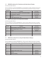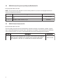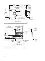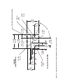
1
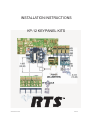
INSTALLATION INSTRUCTIONS
KP-12 KEYPANEL KITS
9330-7497-003 Rev B
05/2004
2
PROPRIATARY NOTICE
The RTS product information and design disclosed
herein were originated by and are the property of
Telex Communications, Inc,, Telex reserves all patent,
proprietary design, manufacturing, reproduction, use
and sales rights thereto, and to any article disclosed
therein, except to the extent rights are expressly
granted to others.
COPYRIGHT NOTICE
Copyright 2004 by Telex Communications, Inc. All
rights reserved. Reproduction in whole or in part
without prior written permission from Telex is prohibited.
UNPACKING AND INSPECTION
Immediately upon receipt of the equipment, inspect
the shipping container and the contents carefully for
any discrepancies or damage. Should there be any,
notify the freight company and dealer at once.
TECHNICAL SUPPORT
Technical questions should be directed to:
Factory Service Department
Telex Communications, Incorporated
West 1st Street
Blue Earth, MN 56013 U.S.A
RETURN SHIPPING INSTRUCTIONS
Procedure for returns
If a repair is necessary, contact the dealer where the
unit was purchased.
If repair through the dealer is not possible, obtain a
RETURN AUTHORIZATION from:
Customer Service Department
Telex Communications, Inc.
Telephone:
800-392-3497
Fax:
800-323-0498
DO NOT RETURN ANY EQUIPMENT DIRECTLY
TO THE FACTORY WITHOUT FIRST OBTAINING
A RETURN AUTHORIZATION.
Be prepared to provide the company name, address,
phone number, a person to contact regarding the
repair, the type and quantity of equipment, a description of the problem and the serial number(s).
SHIPPING TO MANUFACTURER FOR REPAIR OR
ADJUSTMENT
All shipments of RTS products should be made via
United Parcel Service or the best available shipper,
prepaid. The equipment should be shipped in the
original packing carton; if that is not available, use
any suitable container that is rigid and of adequate
size. If a substiture container is used, the equipment
should be wrapped in paper and surrounded with at
least four incesh of excelsior or similar shockabsorbing material. All shipments must be sent to the
following address and must include the Return
Authorization.
Factory Service Department
Telex Communications, Incorporated
West 1st Street
Blue Earth, MN 56013 USA
Upon completion of any repair the equipment will be
returned via United Parcel Service or specified
shipper collect.
3
End user License
Important! Please read this document carefully before using this product.
THIS DOCUMENT STATES THE TERMS AND CONDITIONS UPON WHICH TELEX COMMUNICATIONS,
INC, (the “COMPANY”) OFFERS TO LICENSE THE INSTALLED SOFTWARE OR PROGRAM (the “SOFTWARE) FOR USE WITH THE PRODUCT IN WHICH IT WAS INSTALLED. YOU ARE AGREEING TO
BECOME BOUND BY THE TERMS OF THIS AGREEMENT. IF YOU DO NOT AGREE TO THE TERMS OF
THIS AGREEMENT, DO NOT USE THIS PRODUCT. PROMPTLY RETURN THE PRODUCT TO THE
PLACE WHERE YOU OBTAINED IT FOR A FULL REFUND.
The installed software as supplied by the Company is licensed, not sold, to you for use only under the terms of
this license, and the Company reserves all rights not expressly granted to you. You own the product or other
media on or in which the Software is originally or subsequently recorded or fixed, but the Company retains
ownership of all copies of the Software itself.
1.
License: this license allows you to use the Software for internal purposes only on a single product in
which it is installed.
2.
Restrictions: (a) You may not market, distribute or transfer copies of the Software to others or electronically transfer or duplicate the Software. YOU MAY NOT REVERSE ENGINEER, DECOMPILE, DISASSEMBLE, MODIFY, ADAPT, TRANSLATE, RENT, LEASE OR LOAN THE SOFTWARE OR CREAT DERIVATIVE WORKS BASED ON THE SOFTWARE OR ANY ACCOMPANYING WRITTEN MATERIALS. (b) The
Software and the accompanying written materials are copyrighted. Unauthorized copying of the Software,
including portions thereof or the written materials, is expressly forbidden. (c) You understand that the Company may update or revise the Software and in so doing incurs no obligation to furnish such updates to you.
3.
Limited Warranty: The Company does not warrant that the operation of the Software will meet your
requirements or operate free from error. The Company DISCLAIMS ALL OTHER WARRANTIES AND CONDITIONS EITHER EXPRESS OR IMPLIED, INCLUDING THE WARRANTIES OF MERCHANTABILITY,
FITNESS FOR A PARTICULAR PURPOSE AND NON-INFRINGEMENT OF THIRD PARTY RIGHTS.
4.
Limited Liability: The liability of the Company for any claims arising out of this License based upon the
Software, regardless of the form of action, shall not exceed the greater of the license fee for the Software or
$50.00.
4
Contents
1 INTRODUCTION ..............................................................................................................................6
2 COMPONENTS OF A KP-12 INTERCOM STATION ........................................................................6
2.1 Control and Audio Receive PC Board .....................................................................................7
2.2 Audio Transmit PC Board .........................................................................................................7
2.3 Dual Shaft Encoder and Dual Display PC Boards ...................................................................8
2.4 Key Modules ............................................................................................................................8
2.5 General Purpose Interface Module GPI) ..................................................................................9
2.6 Connector Module ...................................................................................................................9
2.7 Power Entry Module .................................................................................................................9
2.8 Frame Interconnect Module .....................................................................................................9
2.9 Power Supply PC Board ..........................................................................................................9
2.9.1 Power Supply Specifications ........................................................................................10
3 KIT PARTS LISTS ..........................................................................................................................11
3.1 KP12-SP Intercom Station Kit with 12 Alpha-Numeric Pushbutton Keys ...............................11
3.2 KP12-SL Intercom Station Kit with 12 Alpha-Numeric Lever Keys .........................................11
3.3 KPM-BASE-S Base Component Kit .......................................................................................11
3.4 KPM-P4 Pushbutton Kit, 4 Pushbuttons without Displays ......................................................12
3.5 KPM-P4A Pushbutton Kit, 4 Pushbuttons with Alpha-Numeric Displays ...............................13
3.6 KPM-L4 Lever Key Kit, 4 Lever Keys without Displays...........................................................13
3.7 KPM-L4A Lever Key Kit, 4 Lever Keys with Alpha-Numeric Displays ....................................13
3.8 KPM-IO General Purpose Input/Output (GPI) Module Kit .......................................................14
3.9 KPM-CK Audio Connector Kit ................................................................................................14
4 Dimensions and Cutouts ................................................................................................................15
5
1
INTRODUCTION
This manual describes the assembly of custom
intercom keypanels using kits based on the RTS™
Systems’ KP-12 Intercom Keypanel. Typical applications of these kits could include desktop intercom
stations, wall- or panel-mounted intercom stations,
rack-mounted intercom stations and hybrid stations
that integrate an intercom station into other equipment. The manual contains a brief description of the
KP-12 design concept and the general requirements
of an intercom station based on this design. Other
general design and construction requirements also
discussed, such as case materials and additional
tools and hardware required to supplement the kits.
This is followed by detailed descriptions and specifications, such as dimensions, hole cutout requirements etc., for the various components. Finally, a
general procedure is suggested for connecting the
components and checking operation. An intercom
station constructed using the standard kit components will operate as described in the KP-12 User
Instructions which are included with the kits.
2
COMPONENTS OF A KP-12
INTERCOM STATION
Figure 1 shows the main components and their
relative positions in a standard KP-12 Keypanel with
all options installed. This figure is provided for
reference purposes only; custom keypanels can
have many different layouts. For example, the KP-12
has 12 intercom keys arranged in a single row; a
custom keypanel could have up to 48 keys (if no GPI
Module is installed) arranged in several rows. The
KP-12 may be optionally equipped with a back panel
connector module; a custom keypanel design could
use a different arrangement of connectors or eliminate these connectors if they are not required. A
gooseneck microphone connector, a speaker, and a
headset connector are all provided on the front panel
of the KP-12; if a custom keypanel will be used as a
headset station only, and space is at a premium, the
gooseneck microphone connector and the speaker
could be eliminated. In the KP-12, the circuit boards
are positioned to permit a rack-mount design only one
rack unit high; a custom desktop intercom station
may need to occupy less horizontal space. In this
situation, one or more circuit boards could be
mounted on the sides of the case. Or, the Audio
Receive and Audio Transmit boards could be stacked
one on top of the other to occupy less space. The
following paragraphs provide detailed descriptions of
the major components.
Figure 1. KP-12 Reference View for Typical Layout of Components
6
2.1
Control and Audio Receive PC Board
This circuit board contains the CPU (central processing unit) for the intercom station. It also contains the
EPROM (eraseable programmable read-only
memory) which defines the keypanel operation and
RAM (random access memory) which stores the
current configuration information for the keypanel,
including the current key assignments and the
keypanel’s current address within the intercom
system. The Control and Audio Receive circuit board
also contains two serial control interfaces. One is an
RS-485 interface for communication with the intercom
system. The other interface is an I2C communication
system, which uses a common bus (in this case, a
ribbon cable) to exchange control information between the CPU and the other devices within the
intercom station itself. In the I2C system, each device
has a unique address, and all control information that
is sent and received by the devices is coded with this
address to assure that it arrives at the correct
location. Table 1 summarizes how I2C devices are
allocated within the keypanel. The I2C bus has a limit
of 15 devices. This limit only becomes an issue when
a large number of Key Modules are connected. For
example, a fully optioned keypanel (includes a GPI
module). is limited to 44 talk/listen keys (11 Key
Modules, with 4 keys per module).
The Control and Audio Receive PC board also
contains all audio circuitry required for a listen-only
intercom station. This includes a balanced intercom
channel audio input, a balanced program input (to
monitor a local audio source only) a 24-watt speaker
amplifier, and a headphone amplifier. the speaker
amplifier can drive an internal loudspeaker, as well as
an optional speaker output at the back panel.
2.2
Audio Transmit PC Board
The Audio Transmit PC Board adds talk-back capability to the intercom station. It contains the following:
•
•
•
•
•
•
an electret mic input
two balanced, dynamic-mic inputs
a balanced, unswitched mic pre-amp output
(hot mic)
a balanced intercom audio output
a tone generator
a sidetone output
Figure 3. Audio Transmit PC Board
Figure 2. Control and Audio Receive PC Board
Table 1. I2C Device Allocation
Ci r c u i t B o ar d o r Mo d u l e
Nu m b er o f I2C
Dev i c es
Control and Audio Receive PC Board
1
Audio Transmit PC Board
1
Dual Encoder Assembly
1
General Pur pose Interface (GPI) Module
1
Talk/Listen Key Module (four keys per module)
1
Fram Interconnect Module
1
The mic inputs provide the flexibility of using either
electret or dynamic type microphones. The mic preamp output is a “hot mic” signal that can be sent to
other equipment. This allows the station operator to
use a common microphone to talk to multiple audio
systems. The balanced intercom audio output sends
the signal from the currently selected mic input to the
intercom matrix. The tone generator can be used to
check the audio path from the keypanel to the intercom matrix and back. The sidetone circuit feeds a
portion of the microphone signal back into the audio
receive circuits on the Control and Audio Receive
Board. In this way, the station operator can hear his
or her own voice in the headphones when using a
headset.
The I2C device on the Audio Transmit board consists
of electronic switches by which the CPU selects the
desired mic source and turns the tone generator on or
off. This I2C device is simply a passive recipient of
control information. It does not send any control
signals back to the CPU. The
7
Audio Transmit PC Board also contains a balanced
intercom line driver which sends the currently selected mic signal, and the tone generator output, if
active, back to the intercom system.
2.3
Dual Shaft Encoder and Dual Display
PC Boards
thick (2.03mm) panel material, this spacing will cause
the front surface of the alpha-numeric displays to be
just behind the front surface of the front panel.
Refer to the KP-12 User Manual for information about
the operation of the shaft encoders.
2.4
The Dual Shaft Encoder PC Board assembles to the
Display PC Board. The two assembled boards
provide the following capabilities:
•
•
•
•
access to the keypanel’s menu-driven
program ming system
independent volume adjustment for speaker
output, headphone output, and the auxilliary
program audio input
caller identification for incoming calls, with
talkback capability
access to the telephone support features
ncluding manual dialing, auto-dialing and
redialing. (Requires an optional TIF-2000
Telephone Interface)
The Dual Shaft Encoder Board contains two, multiposition rotating shaft encoder switches. Each shaft
encoder also has momentary push-button contacts.
The Display Board contains two, four-character
alpha-numeric displays, five status LEDs, and a 16segment LED volume display. The Display Board
plugs into the shaft encoder board and is secured by
washers and nuts on the shaft encoders. There are
five small light pipes for LEDs and a larger light pipe
for the volume display. The entire assembly is
designed for mounting through the front panel of the
intercom station. The volume display light pipe
provides the spacing between the assembled boards
and the intercom case. With .080-inch
Figure 4. Dual Shaft Encoder and Dual Display
PC Boards
8
Key Modules
Each key module provides four, talk/listen keys, with
a choice of pushbutton or lever keys, with and without
four-character, alpha-numeric displays. Each key
module is supplied with a plastic support that provides spacing behind the front panel. With .080-inch
thick (2.03mm) panel material, this spacing will cause
the front surface of the alpha-numeric displays to be
positioned just behind the front surface of the front
panel. Refer to the KP-12 User Manual for information about the operation ofthe keys and displays.
Figure 5. Lever Key Module Components
Figure 6. Pushbutton Key Module Components
2.5
General Purpose Interface Module
(GPI)
The GPI Board provides a means of controlling
external devices from the keypanel and of controlling
the keypanel from external devices. The GPI Module
contains the following:
•
•
•
two DPDT relays, each with two available
pairs of normal-open, normal-closed and
common contacts
two open collector outputs capable of directly
driving TTL or CMOS inputs
four opto-isolated inputs capable of being
driven by TTL or CMOS devices
2.7
Power Entry Module
The power entry module provides a universal power
cord connector, fuse, and on/off switch.
2.8
Frame Interconnect Module
The Frame Interconnect Module provides intercom
system connectors. There is also an expansion
connector for connection of an EKP-Series expansion panel.
2.9
Power Supply PC Board
This versatile, switching type power supply is suitable
for
Figure 7. GPI Module
Figure 10. Frame Interconnect Module
2.6
Connector Module
The connector module provides:
•
•
•
•
An external dynamic-mic input
An external line input for connection of a local
audio source
A mic preamp output connector which can be
turned off via the dual shaft encoder
A connector for an external dynamic-mic
headset. This connector may also be used
with an external electret mic when a front
panel speaker or an external speaker is
being used.
use with AC input voltages from 47 to 260 VAC and
47 to 63Hz. The power supply has enough rated
capacity to power all of the base circuitry plus a few
extra modules. For example, if a GPI module is not
used, up to 6 key modules (24 talk/listen keys) may
be installed. If more key modules are required, a
suitable power supply providing the same output
voltages, but with higher capacity, will have to be
substituted.
Figure 8. Connector Module
Figure 9. Power Supply PC Board
9
2.9.1
Power Supply Specifications
AC Input Voltage: 90 to 260 VAC
AC Frequency: 47 to 63 Hz
AC Input Current (RMS): 0.8 A at 115 VAC; 0.4 A at
230 VAC
DC Outputs: See Table 2
Efficiency: 70% typical at full load
Hold-up Time: 16 msec typical at full load and 115
VAC input
Overcurrent Protection: All outputs equipped with
automatic recovery current limiting circuit
Overvoltage Protection: 5.6 V to 6.5 V on main output
Table 2. Power Supply Ratings (Any substituted supply must meet or exceed the ratings for Ripple and
Total Tolerance)
L o ad
Ou t p u t
Vo l t ag e
Ri p p l e (P-P)
To t al
To l er an c e
Ou t p u t Pi n s
Mi n
Max
@20 CFM
Peak
+5.1V
0.3A
2.0 A
4.0 A
5.0 A
50mV
±2%
2,3
+12 V
0.1 A
1.0 A
1.5 A
2.0 A
120 mV
±5%
1
-12 V
0.0 A
0.3 A
0.3 A
0.5 A
120 mV
± 5%
6
Table 3. Module Maximum Current Requirements
Mo d u l e
+5.1 VDC
+12 VDC
-12 VDC
Control and Audio Receive
80 mA
145 mA
80 mA
Audio Transmit
6 mA
25 mA
45 mA
Dual Encoder and Dual Display
175 mA
0 mA
0 mA
Key Modules
305 mA
0 mA
0 mA
GPI Modules
250 mA
0 mA
0 mA
3 mA
0 mA
0 mA
Frame Interconnect
10
3
KIT PARTS LISTS
3.1
KP12-SP Intercom Station Kit with 12 Alpha-Numeric Pushbutton Keys
Kit Part Number 9000-7497-003
This kit contains the basic componenets for an intercom station with 12 pushbutton style intercom keys. Items
not supplied: case, component mounting hardware, and matrix interconnect cables.
Qu an t i t y
3.2
Des c r i p t i o n
Par t Nu m b er
1
KPM-BASE-S Base Component Kit (Includes installation instructions)
9010-7497-010
3
KPM-P4A Pushbutton Kit, 4 Pushbuttons with Alpha-Numeric Displays
9010-7497-005
1
KP-12 User Instructions, Pushbutton Version (Rev E or later)
9350-7497-001
KP12-SL Intercom Station Kit with 12 Alpha-Numeric Lever Keys
Kit Part Number 9000-7497-004
This kit contains the basic components for an intercom station with 12 lever style intercom keys. Items not
supplied: case, component mounting hardware, and matrix interconnect cables.
Qu an t i t y
Des c r i p t i o n
Par t Nu m b er
1
KPM-BASE-S Base Component Kit (Includes installation instructions)
9010-7497-010
3
KPM-L4A Lever Key Kit, 4 Lever Keys with Alpha-Numeric Displays
9010-7497-006
1
KP-12 User Instructions, Lever Key Version (Rev B or later)
9350-7497-002
3.3 KPM-BASE-S Base Component Kit
Part Number 9000-7497-010
This kit contains the basic components for an intercom station. Pushbutton or lever key kits are required to
complete the intercom station. Items not supplied: case, component mounting hardware, and matrix
interconnect cables.
11
Qu an t i t y
Des c r i p t i o n
Par t Nu m b er
1
PC Board Assembly, Control and Audio Receive
9030-7725-000
1
PC Board Assembly, Audio Transmit
9030-7725-500
1
PC Board Assembly, Matrix Frame Interconnect
9030-7506-000
1
PC Board Assembly, Power Supply
532024-000
1
PC Board Assembly, Dual Display
9030-7508-000
1
PC Board Assembly, Dual Encoder
9030-7709-500
1
Light Pipe, Volume Indicator for Dual Encoder
700501-000
5
Light Pipe, Call, Menu, Hdst, Spkr, Prgm Indicators for Dual Encoder
700502-000
2
Knob, Select and Volume for Dual Encoder
590218-000
1
Speaker and Wire Connector Assembly
1
Bushing, Gooseneck Mic Connector
9160-7028-001
1
Bushing, Gooseneck Mic Connector
700678-000
1
Lock Washer, Gooseneck Mic Connector Mounting
585025-000
1
Nut, 5/8 - 18, Gooseneck Mick Connector Mounting
585016-000
1
Gooseneck Mic Jack and Wire Connector Assembly
800162-000
1
Headset XLR4RF Panel Mount Connector and Wire Connector Assembly
800163-000
2
800169-000
1
Cable, Ribbon, 5ft. (1.5 m), I C Bus Signal and Power Distribution
57799-001
5
I2C Ribbon Cable Connector, 10 Pin
57739-001
1
Cable Assembly, Frame Interconnect to Audio Receive and Transmit Boards
800166-000
1
Cable Assembly, Audio Receive and Transmit Board Power Distribution
800167-010
1
Cable Assembly, Sidetone
800212-000
1
KP-12 Custom Keypanel Kit Instructions
1
Cable, Ribbon, 6 inches (digital control for compression)
9330-7497-003
800168-003
3.4 KPM-P4 Pushbutton Kit, 4 Pushbuttons without Displays
Kit Part Number 9000-7497-011
This kit is intended for used with the KPM-BASE-S Kit. Each pushbutton kit adds 4 pushbutton intercom keys.
Also order one copy of KP-12 User Instructions, Pushbutton Version (specify Rev E or later) part number
9350-7497-0001.
Quantity
12
Description
Par t Number
1
PC Board Assembly, 4 Pushbutton, No Display
9030-7708-014
1
PC Board Suppor t, Pushbutton
9110-7497-000
2
Nut, 4-40
50033-022
1
I2C Ribbon Cable Connector, 10 Pin
57739-001
3.5
KPM-P4A Pushbutton Kit, 4 Pushbuttons with Alpha-Numeric Displays
Kit Part Number 9000-7497-005
This kit is intended for use with the KPM-BASE-S Kit. Each pushbutton kit adds 4 pushbutton intercom keys.
Also, order one copy of KP-12 User Instructions, Pushbutton Version (specify Rev E or later) part number
9350-7497-001.
Quantity
3.6
Description
Par t Number
1
PC Board Assembly, 4 Pushbuttons, 4 Alpha-Numeric Displays
9030-7708-004
1
PC Board Suppor t, Pushbutton
9110-7497-000
2
Nut, 4-40
50033-022
1
I2C Ribbon Cable Connector, 10 Pin
57739-001
KPM-L4 Lever Key Kit, 4 Lever Keys without Displays
Kit Part Number 9000-7497-012
This kit is intended for use with the KPM-BASE-S Kit. Each lever key kit adds 4 intercom keys. Also order
one copy of the KP-12 User Instructions, Lever Key Version (specify Rev B or later) part number 9350-7497002.
Quantity
3.7
Description
Par t Number
1
PC Board Assembly, 4 Pushbuttons, No Display
9030-7708-018
1
PC Board Suppor t with Pin, Lever Key
9110-7497-001
2
Nut, 4-40
50033-022
1
I2C Ribbon Cable Connector, 10 Pin
57739-001
4
Lever Key
700504-000
4
Light Pipe, Lever Key
700499-000
KPM-L4A Lever Key Kit, 4 Lever Keys with Alpha-Numeric Displays
Kit Part Number 9000-7497-006
This kit is intended for use with the KPM-BASE-S Kit. Each lever key kit adds 4 intercom keys. Also order
one copy of KP-12 User Instructions, Lever Key Version (specify Rev B or later) part number 9350-7497-002.
Qu an t i t y
Des c r i p t i o n
Par t Nu m b er
1
PC Board Assembly, 4 Lever Key, 4 Alpha-Numeric Display
9030-7708-008
1
PC Board Suppor t with Pin, Lever Key
9110-7497-001
2
Nut, 4-40
50033-022
1
I2C Ribbon Cable Connector, 10 pin
57739-001
4
Lever Key
700504-000
4
Light Pipe, Lever Key
700499-000
13
3.8
KPM-IO General Purpose Input/Output (GPI) Module Kit
Kit Part Number 9000-7497-022
NOTE: This kit should not be ordered for use on a factory-built KP-12, since it is not equipped with the required mounting plate and spacers.
Qu an t i t y
3.9
Des c r i p t i o n
1
BPI Assembly, 4 Relays, 2 Open Collector Outputs, 4 Opto-Isolator
Inputs
1
I2C Ribbon Cable Connector, 10 pin
Par t Nu m b er
9020-7505-000
57739-001
KPM-CK Audio Connector Kit
Kit Part Number 9000-7497-023
This kit contains pre-wired connector assemblies for external connection of microphone, speaker, program
input, unswitched balanced mic preamp output, and dynamic-mic headset. This kit should not be ordered for
use on a factory-built KP-12, since it is not equipped with the required mounting plate and spacers.
Qu an t i t y
Des c r i p t i o n
Par t Nu m b er
1
Connector Panel Assembly, with 3-Conductor 1/4-inch Phone Jack (Speaker),
DE9P Connector (Headset), and 3 XLR3F Audio Connectors (Mic Preamp
Out, Program In., Ext. Mic. In.). Includes Wire Connectors to PC Boards
9020-7497-002
14
4
Dimensions and Cutouts
5.200
(132.08)
3.421
(86.89)
0.218
(5.54)
2.000
(50.80)
1.045
(50.80)
0.871
(22.12)
.125 DIA.
(3.17 DIA.)
0.953
(24.21)
0.062
(1.57)
INCHES
(MILLIMETERS)
0.845
(21.46)
NOT TO SCALE
Figure 11. Control and Audio Receive PC Board Dimensions (Not shown to scale)
0.953
(24.21)
5.200
(132.08)
0.830
(21.08)
2.000
(50.80)
1.045
(26.54)
.125 DIA.
( 3.18)
0.871
(22.12)
3.421
(86.89)
INCHES
(MILLIMETERS)
BETWEEN MOUNTING
HOLE CENTERS
NOT TO SCALE
Figure 12. Audio Transmit PC Board Dimensions (Not shown to scale)
15
2.594
(65.89)
0.443
(11.25)
0.062
(1.57)
0.984
(24.99)
1.825
(46.36)
1.000
(25.40)
1.560
(39.62)
INCHES
(MILLIMETERS)
0.413
(10.46)
NOT TO SCALE
Figure 13. Dual Shaft Encoder PC Board Dimensions (not to scale)
INCHES
(MILLIMETERS)
1.850
(46.99)
0.367
(9.32)
0.900
(22.86)
.125 DIA.
(3.18)
1.560
(39.62)
0.735
(18.67)
0.485
(12.32)
0.400
(10.16)
1.000
(25.40)
.300 DIA.
(7.62)
NOT TO SCALE
Figure 14. Dual Display PC Board Dimensions (not to scale)
16
0.062
(1.57)
17
.270 DIA.
(6.86)
0.557 0.488
(14.15) (12.40)
0.408
(10.36)
0.358
(9.09)
1.000
(25.40)
0.815
(20.70)
0.500
(12.70)
1.800
(45.72)
1.850
(46.99)
Figure 15. Cutout Dimensions for the Dual Display PC Board (scale not assured)
SCALE NOT ASSURED
0.957
(24.31)
.125 DIA.
(3.18)
INCHES
(MILLIMETERS).
68°
.050 R.
(1.27)
0.450
(11.43)
0.485
(12.32)
1.560
(39.63)
(7.42)
.292 R.
.392 R.
(9.96)
DISPLAY BOARD OUTLINE
INCHES
(MM)
0.826
(20.98)
3.304
(83.92)
1.652
(41.97)
1.560
(39.62)
0.367
(9.32)
0.062
(1.57)
0.909
(23.09)
0.138
(3.51)
.125 DIA.
(3.18)
.250 MAX. DIA. STAND-OFF
(6.35)
3.294
(83.67)
0.821
(20.85)
0.320
(8.13)
1.652
(41.96)
0.755
(19.18)
NOT TO SCALE
Figure 16. Lever Key PC Board Dimensions (not to scale)
18
0.400
(10.16)
0.170
(4.32)
0.104
(2.64)
3.304
(83.92)
0.826
(20.98)
0.590
(14.99)
1.652
(41.97)
1.560
(39.62)
0.366
(9.32)
0.909
(23.08)
0.062
(1.57)
.125 DIA.
(3.18)
0.400
(10.16)
.250 MAX DIA. STAND-OFF
(6.35)
3.294
(83.67)
0.821
(20.85)
0.320
(8.13)
1.652
(41.96)
0.755
(19.18)
NOT TO SCALE
Figure 17. Pushbutton Key PC Board Dimensions (not to scale)
19
20
INDICATES BOARD
OUTLINE
(41.96)
(20.98)
(83.92)
3.304
1.652
0.826
(12.37)
0.487
.706 SQ. CUT OUT
(17.93 SQ.)
(4 PLS)
(8.53)
0.336
(2.87)
.113 DIA.
SCALE NOT ASSURED
(20.98)
(TYP)
0.826
.706 X .400 CUT OUT
(17.93 X 10.16)
(4 PLS)
Figure 18. Panel Cutout Dimensions for Lever Key PC Board and Pushbutton PC Board (scale not assured)
(39.62)
1.560
(16.53)
0.651
(10.16)
0.400
INCHES
(MM)
21
(41.96)
1.652 MIN.
SCALE NOT ASSURED
Figure 19. Minimum Hole Spacing Requirement for Side by Side and Above/Below Key Board Placement (Scale not assured)
(42.16)
1.660 MIN.
INDICATES BOARD
OUTLINE
2.650
INCHES
(MM)
(67.31)
0.019
1.900
(.48)
(48.26)
1.150
1.043
(29.21)
(26.49)
2.170
NOT TO SCALE
(55.12)
Figure 20. Power Entry Module Dimensions (not to scale)
2.600
(66.04)
INCHES
(MM)
1.063
(27.00)
SCALE NOT ASSURED
Figure 21. Power Entry Module Panel Cutout Dimensions (scale not assured)
22
3.000
(76.20)
4.000
(101.60)
INCHES
(MILLIMETERS)
3.600
(91.60)
.160 DIA.
(4.06)
2.600
(66.04)
0.200
(5.08)
1.300
0.200
(5.08)
(33.02)
NOT TO SCALE
Figure 22. Power Supply PC Board Dimensions (not to scale)
2.650
(67.31)
0.530
(13.47)
1.400
(35.56)
1.272
(32.30)
INCHES
(MILLIMETERS)
0.062
(1.57)
0.400
(10.16)
NOT TO SCALE
Figure 23. Frame Connector Module Dimensions (not to scale)
23
.750 DIA.
(19.05)
1.738
(44.15)
0.087
(2.21)
INCHES
(MILLIMETERS)
0.625
(15.88)
0.693
(17.60)
NOT TO SCALE
Figure 24. Gooseneck Microphone Connector Dimensions (not to scale)
INCHES
(MILLIMETERS)
0.077
(1.95)
.299 R (2 PLS)
(7.60)
0.575
(14.60)
BUSHING OUTLINE
.750 DIA.
(19.05)
SCALE NOT ASSURED
Figure 25. Gooseneck Microphone Connector Panel Cutout Dimensions (scale not assured)
24
INCHES
(MILLIMETERS)
1.419
(36.04)
0.374
1.220
0.091
(9.50)
(30.99)
(2.31)
1.060
0.748
(26.92)
(19.00)
0.473
NOT TO SCALE
0.945
(12.00)
(24.00)
Figure 26. XLR Connector Dimensions (not to scale)
INCHES
(MILLIMETERS)
.138 DIA.
(3.51)
0.944
(23.98)
0.748
(19.00)
XLR CONNECTOR
OUTLINE
0.374
(9.50)
0.472
(11.99)
1.220
(30.99)
0.137
(3.48)
.945 DIA.
0.156
(3.96)
(24.00)
SCALE NOT ASSURED
1.060
(26.92)
Figure 27. XLR Connector Panel Cutout Dimensions (scale not assured)
25
5.421 (137.69)
3.310 (84.07)
0.453
(11.51)
2.207 (56.06)
0.062
(1.57)
0.400 (10.16)
1.500 (38.10)
1.103 (28.02)
4.413 (112.09)
INCHES
(MILLIMETERS)
0.400
(10.16)
NOT TO SCALE
Figure 28. GPI Module Dimensions (not to scale)
1.615
1.049
(41.02)
(26.64)
2.795
2.495
(70.99)
(63.37)
INCHES
(MILLIMETERS)
1.315
(33.40)
NOT TO SCALE
29. Speaker Dimensions (not to scale)
26
27
0.653
(16.59)
2.795
(70.99)
1.190
(30.23)
SCALE NOT ASSURED
Figure 30. Speaker Cutout Dimensions (scale not assured)
0.150
(3.81)
.150
(3.81)
1.615
(41.02)
.625 R.
(15.88)
2.496
(63.40)
INCHES
(MILLIMETERS)
.125 DIA.
(3.18)
0.658
(16.70)
SPEAKER
OUTLINE
1.315
(33.40)
1
2
3
1
2
3
4
5
6
MATRIX DATA +
MATRIX DATA -
1
2
3
4
5
6
+12VDC
+5.1VDC
NC
COMMON
COMMON
-12VDC
PIN 1
J1
NC 1
2
3
J1
NC 1
2
3
J1
J3
J4
J10
NC
J1
PIN 1
1
2
3
4
5
CONTROL AND
AUDIO RECEIVE
PC BOARD
(7725-000)
J2
TALK/LISTEN KEY MODULES
AUDIO FROM MATRIX +
AUDIO FROM MATRIX -
AUDIO TO MATRIX +
AUDIO TO MATRIX -
POWER
SUPPLY
PC BOARD
9
4
5
3
8
7
6
1
2
10 NC
J3
FRAME
INTERCONNECT
MODULE
PIN 1
Figure 31. KP-12 Matrix, I2C and Power Connections
1
2
3
CHASSIS
EARTH
GROUND
AC LINE (L)
AC NEUTRAL (N)
POWER ENTRY
MODULE
J1
GPI MODULE
1
2
3
4
5
J3
J1
J6 2
1
J7 3
2
1
3
J8 2
1
J9 3
2
1
1
2 J4
J2
J1
DUAL ENCODER
AND
DISPLAY MODULES
J5
NC 1
2
3
2
J7
J6
J5
1
2
3
4
5
2
I C CABLE
J9
PIN 1
J8
J3
ALL I C CONNECTORS
AUDIO TRANSMIT
PC BOARD
(7725-500)
PIN 1
1
2
3
PIN 1
1
2
3
1
2
3
1
2
3
1
2
3
1
2
3
1
2
3
1
2
3
4
5
1
2
3
1
2
3
28
1
2
3
3
2
1
LINE IN LINE IN +
NC
J1
J2
3
2
1
J3
PIN 1
J8
1
2
1
2
1
2
3
1
2
3
1
2
3
J9
1
2
3
4
5
1
2
3
J7
DYNAMIC MIC +
DYNAMIC MIC -
HEADPHONE HEADPHONE +
1
2
J6
1
2
3
AUDIO TRANSMIT
PC BOARD
(7725-500)
J5
1
2
3
1
2 J4
1
2
3
4
5
J10
3
2
NC 1
CONTROL AND
AUDIO RECEIVE
PC BOARD
(7725-000)
1
2
3
PIN 1
J6 2
1
J7 3
2
1
3
J8 2
1
J9 3
2
1
1
2
3
1
2
3
J5
TO CHASSIS
2
1
2
1
2
1
1
2
3
1
2
3
1
2
3
J4
EXT LINE IN
3-PIN FEMALE XLR
3
2
NC 1
NC 1
2
3
J3
DYNAMIC MIC +
DYNAMIC MIC -
SPEAKER +
SPEAKER -
DYNAMIC MIC +
DYNAMIC MIC HEADPHONE HEADPHONE +
ELECTRET MIC +
ELECTRET MIC -
NC
J2
MIC PRE OUT
3-PIN FEMALE XLR
3
2
1 NC
1
6
2 NC
3
4
9
5
8
7
T
R
S
J1
EXT MIC IN
3-PIN FEMALE XLR
MIC PRE OUT MIC PRE OUT +
HEADSET
9-PIN MALE DSUB
3
2
1
SPKR
3-CONDUCTOR
1/4" PHONE JACK
1
2
1
2
R
T
S
FRONT PANEL
GOOSENECK MIC
3-CONDUCTOR
1/4" PHONE JACK
MIC +
MIC -
+ -
FRONT PANEL
DYN-MIC HEADSET
4-PIN FEMALE XLR
1
2
3
4
N/C
1
2
3
3
2
1
DENOTES CABLE SHIELD
DENOTES TWISTED PAIR
Figure 32. KP-12 Audio Connections
29