1
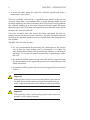
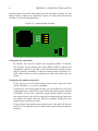
S M A R T
AV I O N I C S
SmartASS Mk2 Air Speed Speaker
Installation and User Manual
Document Revision: 185
Copyright 2005-2007 Smart Avionics Limited.
All rights reserved.
Smart Avionics Limited reserves the right to change or improve its products
at any time without obligation to upgrade or modify existing products.
Unless indicated otherwise, the contents of this document apply to any
revision of the product’s software.
Document Revision History
Revision
179
Date
March 2007
Author
MB
Remarks
Initial version created from Mk1 manual
Contents
1 Introduction
1
1.1 Why speak speed? . . . . . . . . . . . . . . . . . . . . . . .
1
1.2 Overview of installation . . . . . . . . . . . . . . . . . . . .
3
1.3 Specifications . . . . . . . . . . . . . . . . . . . . . . . . . .
4
2 Installing the SmartASS
7
2.1 Setting the configuration switches . . . . . . . . . . . . . . .
7
2.2 Mounting the enclosure . . . . . . . . . . . . . . . . . . . .
9
2.3 Mounting the control panel . . . . . . . . . . . . . . . . . .
9
2.4 Pitot and static connections . . . . . . . . . . . . . . . . . .
10
2.5 Electrical connections . . . . . . . . . . . . . . . . . . . . .
11
2.6 Installation approval . . . . . . . . . . . . . . . . . . . . . .
13
3 Using the SmartASS
15
3.1 The operating modes . . . . . . . . . . . . . . . . . . . . . .
15
3.2 The controls . . . . . . . . . . . . . . . . . . . . . . . . . . .
17
3.3 Zeroing the SmartASS . . . . . . . . . . . . . . . . . . . . . .
20
3.4 Self Test Failure . . . . . . . . . . . . . . . . . . . . . . . . .
21
i
List of Figures
1.1 Enclosure . . . . . . . . . . . . . . . . . . . . . . . . . . . .
3
1.2 Control Panel . . . . . . . . . . . . . . . . . . . . . . . . . .
4
2.1 Configuration Switches . . . . . . . . . . . . . . . . . . . . .
8
2.2 Connections . . . . . . . . . . . . . . . . . . . . . . . . . . .
13
iii
List of Tables
1.1 Specifications . . . . . . . . . . . . . . . . . . . . . . . . . .
4
1.2 D-type connector wiring . . . . . . . . . . . . . . . . . . . .
5
3.1 Mode button functions . . . . . . . . . . . . . . . . . . . . .
19
v
Chapter 1
Introduction
This manual describes how to install and use the Smart Avionics Air Speed
Speaker Mk2 (hereafter referred to as the ‘SmartASS’).
Please read all of this manual before installing and using the
SmartASS. If you have any questions, please send email to
[email protected].
1.1
Why speak speed?
The SmartASS has been developed to provide the pilot of a homebuilt/experimental aircraft with a means of accurately determining their
airspeed without having to look at the airspeed indicator. It does this
by ‘speaking the speed’ in either knots, MPH or KPH through the intercom/radio system and hence into the pilot’s headset.
It can be used during any phase of flight but it has been specifically developed for use during the approach phase when both airspeed and flight path
need to be accurately controlled.
During the approach to a short field or if the conditions are challenging,
both speed and flight path are critical. The SmartASS is helpful because:
1. It reduces the amount of time the pilot has to be looking inside the
cockpit so more attention can be paid to getting the flight path right.
2. It supplies the pilot with airspeed information in a form that is easier to
assimilate than by looking at an ASI.
1
CHAPTER 1. INTRODUCTION
2
3. It warns the pilot when the speed has deviated significantly from a
nominated ‘target speed’.
This last capability (referred to as ‘speed director’ mode) really sets the
SmartASS apart from a conventional ASI. In speed director mode, instead
of simply reporting the current airspeed, the SmartASS will actively monitor
the airspeed, compare it to the target airspeed and then report deviations
from the target speed. The more the airspeed deviates from the target speed,
the more the SmartASS will talk.
Using the SmartASS, once the aircraft has been configured for final approach and the checks have been carried out, the pilot can concentrate on
eyeballing the approach without having to visually check the airspeed every
few seconds.
The Mk2 SmartASS also features:
• A 3-axis accelerometer for measuring the acceleration in the vertical
axis so that the wing loading can be determined – by taking the
wing loading into account, the speed director becomes a ‘stall margin
preserver’ i.e. it assists the pilot in maintaining a speed margin above
the stall.
• An optional audible undercarriage alert that will be triggered when
the speed reduces to the approach speed but the undercarriage is not
down and locked.
• An optional audible general alert that can be triggered by any external
system.
!
Important
Although the SmartASS is accurate and reliable it must not be
the only means of determining airspeed installed in the aircraft. A conventional mechanical ASI must also be installed.
!
Important
The SmartASS is not a stall warning system and it does not
provide a stall warning function.
1.2. OVERVIEW OF INSTALLATION
1.2
3
Overview of installation
Chapter 2 (Installing the SmartASS) covers the installation of the SmartASS
in detail, here we just give an overview.
The SmartASS electronics are contained in a lightweight aluminium enclosure (Figure 1.1) that may be mounted in any convenient position within
the instrument panel. The enclosure is equipped with two air connectors
for plumbing the unit into the aircraft’s pitot and static lines.
The SmartASS’s electrical connections are via a D-type connector. A wiring
harness is provided that connects to a small control panel (Figure 1.2 on
the next page) on to which is mounted a combined volume control + on/off
switch and a push button that selects the mode of operation (talking ASI or
speed director). This panel should be mounted in any suitable location such
that it can be easily accessed while flying. The wiring harness also provides
the connections to the aircraft’s power supply and the audio system that
will deliver the audio to the pilot’s headset.
Figure 1.1: Enclosure
CHAPTER 1. INTRODUCTION
4
Figure 1.2: Control Panel
1.3
Specifications
All temperature specifications refer to the temperature of the SmartASS
enclosure, not the outside air temperature.
Table 1.1: Specifications
Operating
Temperature
Range
Minimum Speed
-40◦ C - 85◦ C
Maximum
Speed
Absolute
Accuracy
(linearity &
offset)
250 Knots / 287 MPH / 462 KPH
25 Knots / 30 MPH / 50 KPH
Silent below this
speed
Not an absolute limit
In the temperature
range 0◦ C - 85◦ C.
Assumes unit has
been recently zeroed
±2%
(continued on next page)
1.3. SPECIFICATIONS
5
Table 1.1: Specifications (cont.)
Repeatability
(pressure
hysteresis)
Supply Voltage
±0.1%
At 25◦ C. For speeds
between 25 and 250
Knots
Reverse polarity
protected
Supply Current
Audio Output
Voltage
Minimum Load
Impedance
Electrical
Connector
Air Connectors
50 mA
1 Volt Peak
Enclosure
Dimensions
Weight
150 x 120 x 40 mm
6-18V
With 200 Ohm load
50 Ohms
15W Female D-Type
6 mm OD push-fit
310 grams
1/8 BSP fittings
available on request
Includes mounting
tabs and connectors
Enclosure 230,
panel/harness 80
The SmartASS is supplied with a pre-wired D-type connector so you should
not need to wire your own. In case you do want to wire your own connector,
Table 1.2 lists the connections.
Table 1.2: D-type connector wiring
1
2
3
Ground
Audio out
Volume A
4
5
RS485 A
+12V Supply
6
Undercarriage down switch
7
8
9
Analog output – airspeed
No connection
Ground
Connect to radio/intercom ground
To radio/intercom audio input
Connect 10K log pot between
Volume A & B
Do not connect
A small fuse is needed to protect
the wiring
Ground when U/C down and
locked
10mV per speed unit (kt/mph/kph)
Internally connected to pin 1
(continued on next page)
CHAPTER 1. INTRODUCTION
6
Table 1.2: D-type connector wiring (cont.)
10
Mode Switch
11
Volume B
12
13
RS485 B
Analog input
14
15
General alert input
Analog output – speed director
Connect normally open switch to
ground
Connect 10K log pot between
Volume A & B
Do not connect
Do not connect – reserved for
future use
Switch to ground to activate alert
Do not connect – reserved for
future use
Chapter 2
Installing the SmartASS
Installation of the SmartASS consists of the following steps:
1. Setting the configuration switches (if necessary).
2. Mounting the enclosure within the instrument panel.
3. Mounting the control panel on the instrument panel.
4. Connecting the pitot and static connections.
5. Connecting the power supply and audio output wires and, optionally,
the undercarriage and general alert wires.
6. Carry out a one-time initialisation procedure that orientates the accelerometer.
2.1
Setting the configuration switches
If you wish to change the speed units from the default setting of Knots or
enable the undercarriage alert, you will need to access the configuration
switches on the circuit board. To gain access to the board, remove the four
M4 screws and the top cover.
Four switches are located together in one block under the flat cable that
connects the circuit board to the D-type connector. One other switch is
located about 2cm away (4 o’clock position) from the block of 4. All the
switches have yellow tops and a small arrow that shows the direction the
switch must be moved to turn it on. Use the end of a small screwdriver or
7
CHAPTER 2. INSTALLING THE SMARTASS
8
pencil to move the switch and make sure that the other switches are not
moved also (it’s rather easy to do that). Figure 2.1 shows the layout of the
switches (in their default positions).
ON
VOL HI
UCA
KPH
MPH
ON ON ON ON
Figure 2.1: Configuration Switches
Configuring the speed units
By default, the SmartASS reports the airspeed in Knots. If desired,
the airspeed can be reported in either MPH or KPH by closing the
appropriate switch. If you look at the circuit board you will see that
the first switch is labelled MPH and the second switch is labelled KPH.
Slide either switch to the on position to select the speed unit you
desire.
Configuring the undercarriage alert
If you want to use the undercarriage alert feature, move the third
switch (labelled UCA) to the on position.
If you have a retractable undercarriage, you can enable this alert even
if you don’t have a switch that signals when the undercarriage is down
and locked. In that case, whenever speed director mode is entered,
the undercarriage alert will be triggered to remind you to check that
the wheels are down. Once the alert has sounded, briefly press the
mode button to cancel the alert.
If you do have the undercarriage down switch, the alert will be suppressed if the undercarriage is down when speed director mode is
entered.
2.2. MOUNTING THE ENCLOSURE
9
Reducing the audio volume
The single switch that is nearer to the edge of the board selects the
maximum audio volume. By default, this switch will be on and that
gives the maximum audio output volume. If you find that the audio
output is very loud, this switch can be moved to the off position to
reduce the audio volume.
!
Important
The circuit board contains components that may be damaged
by static electricity. Try to avoid touching the components
on the board and, if possible, remove any static charge that
you may be carrying by touching something that is earthed
before handling the unit.
After the switches have been configured, check that the flat cable connector
is still securely plugged into the socket on the circuit board and replace the
cover and screws.
2.2
Mounting the enclosure
The enclosure can be mounted in any convenient position within the instrument panel area. Four M5 mounting holes are provided. If possible, mount
close to the centreline of the aircraft to minimise the effect of roll on the
accelerometer readings. Remember to leave adequate space for the D-type
conector and the wiring harness (a minimum of 65 mm should be allowed).
The length of the wires between the enclosure and the control panel is 1
metre.
The enclosure can be mounted in any orientation. Although the SmartASS is
robust, avoid subjecting it to excessive vibration or extremes of temperature.
2.3
Mounting the control panel
The control panel holds the combined on/off switch + volume control
and the mode button. It should be mounted in a position such that the
mode button can easily be operated while flying. How exactly this panel is
mounted depends on the thickness of the surrounding instrument panel.
10
CHAPTER 2. INSTALLING THE SMARTASS
If the instrument panel is no more than 4mm thick, the SmartASS control
panel can simply be mounted by drilling two holes (one for the potentiometer and the other for the push switch) and then mounting those controls
through the instrument panel. The SmartASS control panel will be held in
place by the nuts that fasten the controls to the instrument panel.
The hole required for the potentiometer is 9.5mm diameter and the hole for
the mode switch is 6.5mm diameter. The distance between the hole centres
is 23mm.
If the instrument panel is more than 4mm thick, several alternatives are
possible:
1. Mount the SmartASS control panel on a sub-panel which is not more
than 4mm thick (as described above) and then mount the sub-panel
somewhere.
2. If it is possible to locally reduce the thickness of the instrument panel
to 4mm or less by removing material behind where the SmartASS panel
is to be located, then that would allow the controls to be mounted as
described above.
3. The instrument panel could be cut away sufficiently to allow the bodies
of the controls to pass through it. The control panel can then either be
bonded to the front of the instrument panel or it could be drilled near
the corners to accept small screws to hold it to the instrument panel.
The controls would then be attached to the SmartASS panel using their
fixing nuts.
4. The SmartASS control panel could be discarded altogether and the controls mounted in some other way of your own devising.
However the controls are mounted, take care to ensure that the wires are not
subject to excessive strain and that they cannot vibrate enough to fracture
the terminals. If the cables are too long, coil them up and secure with cable
ties.
2.4
Pitot and static connections
Depending on the model purchased, the enclosure is equipped with either
push-fit pneumatic connectors suitable for hose with an outside diameter
of 6 mm or 1/8 BSP female connectors.
2.5. ELECTRICAL CONNECTIONS
11
If using the push-fit connector version, the hose must be of the correct
outside diameter (6mm) and have a smooth surface. Ensure that the hose
ends are cleanly cut and that the hoses are inserted fully into the connectors.
To remove a hose from the connector, you must push the blue plastic part
of the connector towards the threaded body while pulling the hose out.
Exactly how the pitot and static connections are plumbed into the aircraft’s pitot and static lines will be different for each aircraft but, generally
speaking, tee connectors can be inserted into the existing lines so that the
SmartASS is connected in parallel with the existing ASI. Take care to ensure
that all the connections are sound and that no leaks are present.
!
Important
Once the installation is completed, carry out a leak test on
the pitot and static lines to ensure that no leaks have been
introduced.
2.5
Electrical connections
For basic audio output , just three wires need to be connected:
Black wire (ground)
This is connected to the main ground busbar or a ground associated
with the radio or audio system.
Red wire (power)
This is connected to +12V via a fuse or circuit breaker. The current
requirement of the SmartASS is very small so the fuse rating need not
be more than 1A.
White wire (audio output)
This is connected to an auxiliary or music input of the aircraft’s existing
radio/intercom/audio panel installation. Exactly where this should be
connected obviously depends on the specific equipment being connected to.
Development of the SmartASS was carried out in conjunction with a
Flightcom 403mc intercom unit and the output was simply connected
to the ‘Aux input’ of that unit.
CHAPTER 2. INSTALLING THE SMARTASS
12
In most installations, the audio output wire probably doesn’t need to
be shielded unless it is very long or it runs near to a source of electrical
noise. If you wish to shield the wire, the easiest way of doing that is
to remove the braded shield intact from a piece of shielded cable and
slip that over the audio output wire, connecting one end of the shield
to ground. Heatshrink sleeving can be used to stop the ends of the
shield from fraying
If you wish to use the audio alerts, two more wires can be connected:
Purple wire (undercarriage warning)
If you want to use the undercarriage warning facility, provide a switch
that connects the short purple wire to ground when the undercarriage
is down and locked. When the undercarriage alert is activated, you will
hear: ‘ding! check wheels down, ...’. Pressing the mode button briefly
will silence the alert. Remember to enable this feature by setting the
appropriate configuration switch as described on Page 8. If you don’t
want to use it, just leave the purple wire unconnected.
Yellow wire (general alert)
Switching this wire to ground will trigger the general audible alert.
When the general alert is activated, you will hear: ‘ding! alert, ...’.
Pressing the mode button will silence the alert. If you don’t want to
use it, just leave the yellow wire unconnected.
All of the long wires should be trimmed to length rather than coiled up if
they are longer than you require.
Ensure that the screws that fasten the D-type connector to the SmartASS are
reasonably tight so that the connector will not come adrift.
Figure 2.2 on the facing page shows the connections to the SmartASS enclosure.
Note
Intercoms and radios often have the ability to mute the auxiliary
input when radio transmissions are being received. It is up to you
to decide whether to mute the output from the SmartASS or not.
During development, it was found that muting the SmartASS when
radio messages were received was distracting because its spoken
messages were broken up. It was better to not mute the SmartASS
2.6. INSTALLATION APPROVAL
13
but, instead, to keep its volume fairly quiet so you can still easily
hear radio transmissions.
Note
If the volume of the SmartASS’s output is not well matched to the
sensitivity of the existing equipment’s input and that equipment has
no means of adjusting its sensitivity, please contact Smart Avionics
for advice.
Figure 2.2: Connections
ON / OFF
Smart Avionics SmartASS
Serial No:
Date:
PITOT
STATIC
SmartASS
MODE
(Yellow) General Alert
(Purple) Undercarriage Alert
PITOT
STATIC
(Black) Ground
(White)
Auxiliary Input
Intercom/radio
2.6
(Red)
+12V Fused Supply
Installation approval
Before the aircraft can be flown with the SmartASS installed, the installation
has to be approved. Exactly how this is achieved differs from country to
country.
14
CHAPTER 2. INSTALLING THE SMARTASS
In the UK, the installation must be inspected and approved by your PFA
inspector and an entry made in the airframe log book. The PFA will need to
be informed that the SmartASS has been fitted.
Chapter 3
Using the SmartASS
3.1
The operating modes
The SmartASS has three modes of operation:
Talking ASI Mode
This mode simply speaks the current airspeed every few seconds. The
repeat period can be 3, 6 or 12 seconds. Also, if the speed changes
very rapidly, the new speed is spoken straight away.
When the speed is less than 25 Knots (30 MPH, 50 KPH) the voice is
muted. When the SmartASS is turned on, it always starts in talking ASI
mode.
Speed Director Mode
In this mode, the airspeed is continuously measured and compared to
a target speed. The SmartASS reports as follows:
• If the speed is within 5% of the target speed, it says ‘Speed Good’
every 8 seconds
• If the speed is between 5% and 10% too fast, it says ‘Fast’ every
4 seconds.
• If the speed is between 5% and 10% too slow, it says ‘Slow’ every
4 seconds.
• If the speed is between 10% and 15% too fast, it says ‘Very Fast’
every 2 seconds.
15
CHAPTER 3. USING THE SMARTASS
16
• If the speed is between 10% and 15% too slow, it says ‘Very Slow’
every 2 seconds.
• If the speed is more than 15% too slow or too fast, the appropriate
message is prefixed with a chime.
As the wing loading increases, the SmartASS estimates how much this
will increase the stall speed and it subtracts that amount from the
current airspeed. If the pilot ‘pulls G’, the SmartASS will immediately
report that the aircraft is slow even though the actual airspeed has
not (yet) changed. Unloading the wing will immediately make the
SmartASS report a speed increase1 .
If the speed drops to below 80% of the target speed or is above 125%
of the target speed, the SmartASS reverts to talking ASI mode.
Speed director mode is entered automatically when the speed falls to
within 5% of the target speed.
In speed director mode, the volume of the voice will automatically
reduce the longer you stay within a given speed band. So if the air
is smooth and you are flying accurately, the ‘Speed Good’ messages
will become quieter and quieter as you progress towards the runway
threshold. If the speed strays into another speed band, the volume
immediately increases back to the original level.
Note
• Always trim the aircraft accurately for the chosen approach
speed.
• Try not to ‘chase’ the airspeed, especially when the air is
rough.
• Unless the airspeed is wildly wrong, don’t make large adjustments to the airspeed.
• Aim to smoothly increase or decrease the speed to keep the
‘speed good’.
• The airspeed cannot change instantly, it takes a few moments for a change in attitude or power to have an effect
on the airspeed and a bit longer for the SmartASS (and your
mechanical ASI) to measure that speed.
1
The SmartASS ignores reduced G (less than +1) so it will not be fooled into telling you
that you are fast if you move the stick forward rapidly.
3.2. THE CONTROLS
17
Sleep Mode
In this mode, the SmartASS doesn’t say anything at all. It doesn’t even
snore! Sleep mode continues until:
• The pilot briefly presses the mode button to enable talking ASI
mode. Typically, this could occur downwind in the circuit as the
pilot prepares for the approach and landing.
• The airspeed reduces to within 5% of the target speed and the
SmartASS automatically wakes up in speed director mode.
• The general alert is triggered.
3.2
The controls
The SmartASS has been designed to be very easy to use. Just two controls
are provided:
1. Volume control + on/off switch
2. Mode button
The combined on/off switch and volume control works in the conventional
manner: turning the volume control clockwise increases the volume of the
speech. Turning the volume control anti-clockwise reduces the volume and
when turned fully anti-clockwise, switches off the power to the SmartASS.
When the SmartASS is switched on, it says ‘Airspeed in Knots2 ’ and then if
the unit auto-zeros itself it will say ‘Zeroed’. Section 3.3 on page 20 has
more information about zeroing.
If the unit has not yet been orientated, it will also say ‘G disabled’. Page 19
describes how the unit is orientated.
!
Important
If when the SmartASS is switched on the airspeed is at least 25
Knots (30 MPH, 50 KPH), the voice will say ‘Compare to ASI’
after the speed is first reported. This is to remind the pilot
to check that the spoken speed is consistent with the speed
2
Or MPH or KPH depending on the units selected during installation.
CHAPTER 3. USING THE SMARTASS
18
indicated on the ASI. If the speeds tally, the SmartASS can
be considered trustworthy. If there is a significant difference
between the spoken speed and the speed shown on the ASI,
the SmartASS should not be used until the discrepancy has
been investigated.
The mode button has three primary functions:
Silencing an alert message
If either of the undercarriage or general alerts sound, they can be
silenced by pressing the mode button briefly.
Selecting the operating mode
Pressing the mode button briefly3 , toggles the mode of operation between talking ASI mode and either speed director or sleep modes.
When in talking ASI mode, if the airspeed is no more than 125%
of the target speed, pressing the mode button briefly will change to
speed director mode, otherwise, sleep mode is entered. Irrespective of
the current airspeed, pressing the mode button briefly twice in quick
succession will always enter sleep mode. Pressing the mode button
briefly when in either speed director or sleep modes will change to
talking ASI mode.
The mode change is announced as follows:
Talking ASI mode is selected
The SmartASS says ‘Airspeed’ and then starts to speak the airspeed.
Speed director mode is selected
The SmartASS announces the (previously captured) target airspeed by saying ‘Target speed is ...’. Listen to the number it says
and confirm that is the speed you want. If the number it says is
not what you want, you will need to capture a new airspeed as
described below.
Sleep mode is selected
The SmartASS says ‘Goodbye’ and then goes silent.
Note
3
When you press the button briefly, you don’t hear any audio feedback (no beep).
3.2. THE CONTROLS
19
Until an airspeed has been captured, the SmartASS will not
select speed director mode.
Capturing the target airspeed
Pressing the mode button for more than 1/2 second ‘captures’ the
current airspeed and switches to speed director mode if that mode
is not already active. An audio ‘beep’ sounds after the button has
been pressed for enough time to capture the airspeed. The new target
airspeed will be announced as ‘Target speed is ...’ and will be stored
until another speed is captured. The target airspeed is remembered
even when the power is off.
The mode button also has these secondary functions:
Selecting the airspeed repeat rate
By default, the airspeed is repeated every 6 seconds in talking ASI
mode. This period can be altered by holding the mode button until two
beeps are heard. This will cycle the airspeed repeat period between
the values of 3, 6 and 12 seconds. When the button is released, you
should hear the message ‘Repeat period is ...’. The selected value is
remembered when the power is off.
Orientating the accelerometer
Once the SmartASS has been installed, the unit must be orientated so
that it knows which way is up. With the aircraft positioned in the flying
attitude, hold the mode button until three beeps are heard. When the
button is released you should hear the message ‘Orientation set’. The
orientation is remembered when the power is off and this operation
only needs to be repeated if the SmartASS is re-positioned.
This orientation operation can be carried out in flight – just take care
to ensure that the aircraft is flying straight and level and that you are
not subject to any vertical accelerations at the time.
This table summarises the operation of the mode button:
Table 3.1: Mode button functions
Button Interaction
1 short press
Effect
Silence alert
(continued on next page)
CHAPTER 3. USING THE SMARTASS
20
Table 3.1: Mode button functions (cont.)
Button Interaction
1 short press
2 short presses
Hold for 1 beep
Hold for 2 beeps
Hold for 3 beeps
3.3
Effect
Toggle between talking ASI and speed
director or sleep modes
Enter sleep mode
Capture current airspeed and enter
speed director mode
Cycle through airspeed repeat periods
Orientate accelerometer
Zeroing the SmartASS
To ensure the airspeed reported by the SmartASS is as accurate as possible,
the unit requires zeroing occasionally. This will remove any offset error
introduced as the pressure sensor and the electronic components age.4
Whenever the SmartASS is turned on, as long as the current differential
pressure is small, it will be zeroed automatically to remove the offset error.
If the differential pressure is not small when the unit is turned on, this
auto-zeroing will not occur.
It is possible to manually zero the SmartASS at any time by turning the unit
on while pressing the mode button. When the voice says ‘Zeroed’, take your
finger off the mode button.
!
Important
To ensure that the reported speed is accurate, do not manually zero the SmartASS if any of the following are true:
• The aircraft is moving at more than walking pace.
• The wind is blowing into the pitot and it is more than
a very gentle breeze.
• The pitot cover is in position.
4
Due to the fact that airspeed is proportional to the square root of the dynamic pressure,
the effect of a small offset error in the pressure measurement is only really significant at
very low airspeeds. It’s still worth removing the error to get the best possible result.
3.4. SELF TEST FAILURE
21
It is expected that in normal use, auto-zeroing will occur from time to time
and so it should not normally be necessary to manually zero the SmartASS
unless you believe the reported airspeed is incorrect.
3.4
Self Test Failure
When the SmartASS is turned on, it carries out a sequence of tests to check
that it is functioning correctly. If any of the tests fail, the SmartASS goes into a
loop, continuously reporting the failure through the audio interface. For all
of the tests except one, the failure is reported as ‘ding! fail number ’ where
number is the error code for the particular test that has failed. However, if
the Flash Memory that holds the voice data cannot be accessed, the failure
message can’t be played and so, instead, the error is signaled by bursts of
random noise.
So to summarise, if you turn the SmartASS on and you hear regular bursts of
random sound5 then it means that it has a problem with the Flash Memory.
Otherwise, if you hear a message ‘ding! fail ...’ being repeated it means some
other problem has occurred. In either case, please switch off the SmartASS
and contact Smart Avionics to resolve the problem.
5
Sounds a bit like the radio when a very weak transmission is received.
Index
A
accelerometer
orientation, 19
airspeed
capturing, 19
repeat rate, 19
alert, 12
undercarriage, 8
installation
approval, 13
K
Knots, 8
KPH, 8
M
mode
button, 18
modes of operation, 15
MPH, 8
mute
audio input, 12
C
capturing airspeed, 19
check wheels down, 12
configuring
speed units, 8
undercarriage alert, 8
connections
electical, 11
pitot and static, 10
control panel
mounting, 9
O
on/off switch, 17
operating modes, 15
orientation, 19
P
pitot connnection, 10
E
electrical connections, 11
enclosure
mounting, 9
S
self test failure, 21
specifications, 4
speed director mode, 2, 15
static connection, 10
static electricity warning, 9
switch
configuration, 7
F
Fail message, 21
G
G disabled, 17
general alert
wiring, 12
T
talking ASI mode, 15
I
U
23
24
undercarriage warning
wiring, 12
V
volume
reduction switch, 9
volume control, 17
Z
zeroing, 20
INDEX


![manual [372769 bytes]](http://vs1.manualzilla.com/store/data/005891066_1-6553408cfa4c941a2bbbbb48a824c132-150x150.png)