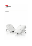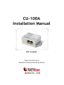
1
CU-100A
Installation Manual
PLC Coupler
Plug into the future
Powerline Communication by Xeline
Xeline Co., Ltd.
CU-100A Installation Manual
Table of Contents
1. Introduction ······························································································· 4
2. Before Installing the CU-100A ·········································································· 5
2.1 Package Contents ························································································································ 5
2.2 Prerequisites································································································································· 5
2.3 Guidelines for Installation ·········································································································· 6
2.4 Safety Precautions······················································································································· 6
3. Getting to Know the CU-100A ·········································································· 7
3.1 Top View········································································································································ 7
3.2 Bottom View ································································································································· 7
3.3 Product Specifications················································································································· 7
4. Installing the CU-100A ··················································································· 8
4.1 Connecting the CU-100A to the MM-202B ················································································· 8
4.2 Extending the CU-100A ··············································································································· 8
4.3 Coupling the CU-100A ················································································································· 9
5. Appendix ·································································································· 14
2
This document is subject to change without prior notice.
CU-100A Installation Manual
Figure Index
Figure 1 XPAS-200B PLC Internet Access System Configuration................................... 4
Figure 2 CU-100A and Coupling Accessories ............................................................... 5
Figure 3 CU-100A Top View ....................................................................................... 7
Figure 4 CU-100A Bottom View.................................................................................. 7
Figure 5 Connecting the MM-202B to the CU-100A ..................................................... 8
Figure 6 CU-100A Extension ...................................................................................... 8
Figure 7 CU-100A Installation Configuration .............................................................. 9
Figure 8 Indoor Coupling Configuration ................................................................... 10
Figure 9 Coupling Core Location ............................................................................. 10
Figure 10 Coupling Wire and Core Installation ......................................................... 11
Figure 11 Coupling Wire and Core Installation Method............................................. 11
Figure 12 Coupling Device Installation .................................................................... 12
Figure 13 Capacitive Coupling 1 .............................................................................. 13
Figure 14 Capacitive Coupling 2 .............................................................................. 13
3
This document is subject to change without prior notice.
CU-100A Installation Manual
1. Introduction
Powerline Communication (PLC) technology uses the existing powerline infrastructure to
transfer high-speed data, eliminating the need for expensive and complicated cable
installation. Because the home or office is already a ‘wired network’ through powerlines,
Xeline’s PLC system offers a cost-effective and easy-to-install Internet access solution from
any electrical outlet.
Xeline's XPAS-200B PLC Internet Access System supports data rates of up to 24Mbps and is
targeted for effective Internet access over powerlines in residential houses or high-rise
building configurations.
The CU-100A is the device that couples the output signals of the PLC Master Unit and
Repeater Unit to the powerlines. There are two methods to couple the signals: magnetic
coupling and capacitive coupling.
Figure 1 XPAS-200B PLC Internet Access System Configuration
4
This document is subject to change without prior notice.
CU-100A Installation Manual
2. Before Installing the CU-100A
2.1 Package Contents
Before installing, first verify that you have all of the following items.
○ CU-100A PLC Coupler
○ Coupling Wires
○ Coupling Devices
○ Coupling Cores
○ Installation Manual
Figure 2 CU-100A and Coupling Accessories
If there is a missing item or any visible damage, notify your service provider or dealer
immediately.
2.2 Prerequisites
In order to install the CU-100A, the following conditions must be met:
(1) Sufficient space to install the CU-100A
(2) RJ-11 cable
Note: The RJ-11 cable is not included with the product because the distance to
each subscriber’s house varies widely according to the configurations. The RJ-11
cable should be a straight cable with wires in the same sequence on both ends.
5
This document is subject to change without prior notice.
CU-100A Installation Manual
2.3 Guidelines for Installation
Please make sure to read the following guidelines before installation.
(1) In apartment/building configurations, the CU-100A should be installed to the
secondary side of the circuit breaker (on the subscriber side).
(2) One CU-100A can support up to 4 subscriber homes in residential building
configurations.
(3) When using the magnetic coupling method, wrapping the wires in the wrong
direction causes communication failure. Make sure to follow the manual
carefully.
(4) When the circuit breakers are sparsely located or when connecting more than 4
houses, it is recommended to extend the CU-100As.
2.4 Safety Precautions
Please make sure to read the following instructions before handling the equipment.
(1) Read all instructions before installing the equipment. Be sure to keep this
manual for further reference.
(2) Please follow all the safety precautions and other installation procedures.
(3) Avoid the following environments:
- Areas with extremely high or low temperatures
- Areas with high humidity or high risk of flooding
- Areas where sudden changes in temperature occur
(4) In outdoor configurations, install the CU-100A at least 1m from the ground to
avoid contact with children or small animals.
6
This document is subject to change without prior notice.
CU-100A Installation Manual
3. Getting to Know the CU-100A
3.1 Top View
Figure 3 CU-100A Top View
RJ-11
(left) Input port
(right) Extension port
3.2 Bottom View
Figure 4 CU-100A Bottom View
Terminal
For connection to the coupling wires (PLC signal coupling)
3.4 Product Specifications
Interface
Dimensions
Specifications
Remarks
RJ-11 2 port
For connection to the MM-202B
Coupling terminal 8 port
For connection to coupling wires
97mm × 50mm × 34mm
(W x D x H)
7
This document is subject to change without prior notice.
CU-100A Installation Manual
4. Installing the CU-100A
4.1 Connecting the CU-100A to the MM-202B
The CU-100A is usually installed near the circuit breaker of each subscriber’s house. Use a
straight RJ-11 cable to connect the MM-202B and CU-100A. The RJ-11 cable is not included
with the MM-202B.
①
Insert one end of the RJ-11 cable in the SIG2 port of the MM-202B.
②
Insert the other end of the cable in the INPUT port of the CU-100A.
Figure 5 Connecting the MM-202B to the CU-100A
4.2 Extending the CU-100A
When installing more than 4 houses or when subscribers are located in different floors or the
circuit breakers are far apart, extend the CU-100As.
It is recommended that the distance between the MM-202B and CU-100A does not exceed
100m at the maximum. Needless to say, signal loss will be greater if the distance between the
MM-202B and CU-100A is far.
Figure 6 CU-100A Extension
8
This document is subject to change without prior notice.
CU-100A Installation Manual
4.3 Coupling the CU-100A
There are two methods to couple the PLC communication signals to the powerlines:
(1) Magnetic Coupling
(2) Capacitive Coupling
4.3.1 Magnetic Coupling
Magnetic coupling is the suitable method for apartment/building configurations. Xeline’s
patented magnetic coupling method makes it possible to work on live wires. 1 CU-100A can
support up to 4 houses as shown below:
CU-100A
RJ-11
MM-202B
Figure 7 CU-100A Installation Configuration
9
This document is subject to change without prior notice.
CU-100A Installation Manual
① Connect the coupling wires to CU-100A as follows:
A.
Unscrew the screws of the coupling terminal.
B.
Insert both ends of wire to each slot (each subscriber uses 2 slots)
C.
Secure the coupling wires tightening the screws.
Subscriber #2
Subscriber #3
Subscriber #1
Subscriber #4
2 terminals per
subscriber
Figure 8 Indoor Coupling Configuration
② The coupling wires are then wrapped around the powerlines leading from the
secondary circuit breaker as shown below:
Figure 9 Coupling Core Location
10
This document is subject to change without prior notice.
CU-100A Installation Manual
A.
Wind the coupling wire around the ferrite core in the order as shown below.
CU-100A
Figure 10 Coupling Wire and Core Installation
B.
Close the ferrite core after winding the wire around one side of the core.
C.
Wrap the coupling wires around the second core in the same fasion. and
putting power cable on the other side.
D.
Close the ferrite core after winding the wire in the same fashion for the
other power cable.
E.
The overview of winding procedure is as shown below:
CU-100A
Figure 11 Coupling Wire and Core Installation Method
11
This document is subject to change without prior notice.
CU-100A Installation Manual
③ Attach the shunt device to the screw part of the circuit breaker as shown in the
following figure.
Figure 12 Coupling Device Installation
12
This document is subject to change without prior notice.
CU-100A Installation Manual
4.3.2 Capacitive Coupling
Capacitive coupling is suitable for general residential house configurations when the MM-202B
is installed on the transformer pole. Coupling wires, coupling cores and magnetic coupling
devices are not needed.
Note: Extreme caution should be taken to avoid electric shock accidents when working with
live powerlines!
① Connect the power cable to the circuit breaker.
② After stripping off both ends of the power cable using a stripper, insert them in the
HOT line and Neutral line terminals as shown below:
Neutral Line
Hot Line
Figure 13 Capacitive Coupling 1
③ Secure the power cables by tightening the screws.
④ When there is only one coupling location, place the two lines far apart as in the figure
below:
Hot Line
Neutral Line
Figure 14 Capacitive Coupling 2
13
This document is subject to change without prior notice.
CU-100A Installation Manual
5. Appendix
z Copyright 2005 Xeline Co., Ltd. All rights reserved.
All Xeline brand product names are trademarks of Xeline Co., Ltd.
Other product and company names mentioned herein are the trademarks of their
respective owners.
z Information in this document is subject to change without notice. No part of this document
may be reproduced or transmitted in any form or by any means, electronical or
mechanical, for any purpose, without the express written permission of Xeline Co., Ltd.
z Xeline Technical Support Center
Address: 7F. Chungjin Bldg. 475-22,
Bangbae 2 dong, Seocho-gu,
Seoul 137-819, Republic of Korea
Telephone: +82 2 598 0980
Facsimile: +82 2 598 0975
E-mail: [email protected]
Website: http://www.xeline.com
14
This document is subject to change without prior notice.