1
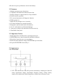
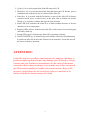
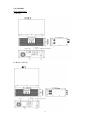
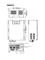
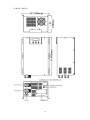
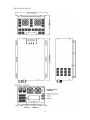
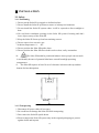
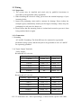
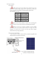
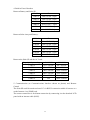
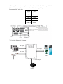
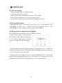
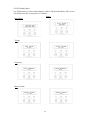
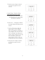
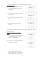
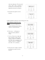
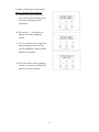
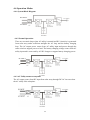
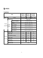
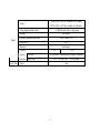
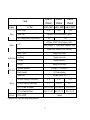
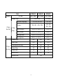
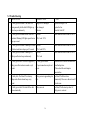
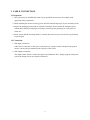
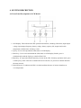
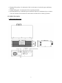
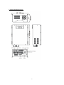
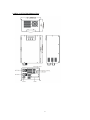
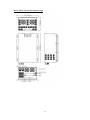
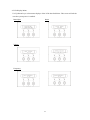
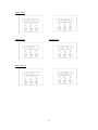
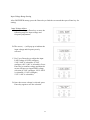
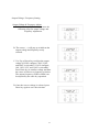
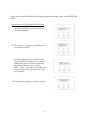
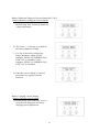
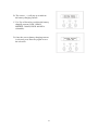
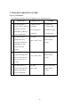
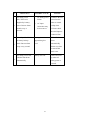
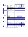
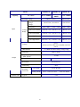
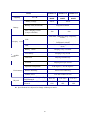
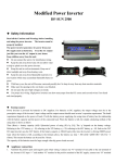
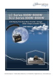
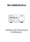
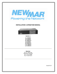
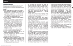
Solar Hybrid Inverter SP Series & SP UPS User Manual This manual includes 2 sections. Section1 is for Solar Hybrid Inverter SP Series; and section 2 is for SP UPS. Please refer to the section depending on what model you bought. 2 (Section 1) Solar Hybrid Inverter SP Series Manual 3 (Section 1)......................................................................................................3 Ⅰ PREFACE.................................................................... 5 1-1 Conventions Used............................................................................................5 1-2 Glossary...........................................................................................................5 Ⅱ INTRODUCTION ......................................................... 5 2-1 Description ......................................................................................................5 2-2 Features............................................................................................................6 2-3 Important Notices ............................................................................................6 2-4 Appearance ......................................................................................................6 2-4-1 Front Panel ...........................................................................................6 2-4-2 Outline..................................................................................................8 Ⅲ INSTALLATION ......................................................... 12 3-1 Safety.............................................................................................................12 3-1-1 Positioning..........................................................................................12 3-1-2 Transporting .......................................................................................12 3-1-3 Installation..........................................................................................13 3-1-4 Operation............................................................................................13 3-1-5 Maintenance and Service ...................................................................13 3-2 Mounting .......................................................................................................14 3-3 Wiring ............................................................................................................15 3-3-1 Inspection ...........................................................................................15 3-3-2 Connection .........................................................................................15 Ⅳ OPERATION.............................................................. 19 4-1 Prior to Startup...............................................................................................19 4-2 Storage Instruction.........................................................................................19 4-3 Operations Procedures for LCD Model.........................................................19 4-4 Operation Modes ...........................................................................................26 Ⅴ NEW LCD SETTINGS ............................................... 28 Ⅵ APPENDIX ................................................................ 30 5-1 Specification ..................................................................................................30 5-2 Trouble Shooting ...........................................................................................36 4 Ⅰ PREFACE 1-1 Conventions Used WARNING Warnings identify conditions that could cause personal injury or loss of life. CAUTION Cautions identify conditions that could cause damage to the unit, other equipment or devices. WARNING: Keep away from unit because of burn hazard BURN resulting from high temperature during operation. HAZARD WARNING: Risk of electric shock caused by energy stored in RISK OF capacitors. Capacitors take time to discharge after ELECTRIC cutting off all power sources. SHOCK 1-2 Glossary AC: Alternating Current DC: Direct Current LCD: Liquid Crystal Display LED: Light Emitting Diode PC: Personal Computer PV: Photovoltaic SNMP: Simple Network Management Protocol Ⅱ INTRODUCTION 2-1 Description The Solar SP series is designed to have access to dual input source; one is AC source from a grid, and the other is DC source from a solar array. This series is a powerful all-in-one solution, not only delivering unsurpassed clean true sine wave output power and combining this with a selectable multistage battery charging current but also converting sunlight into clean energy. This series features durable and continuous 24-hour operation. Consequently, it is applicable to any kind of loads such as air conditioner, home appliances, consumer electronic and office equipment. The built-in 5-stage intelligent charger automatically charges any type of batteries without the risk of overcharge. The compact and modular design makes utility interactive installations easier and more cost effective. It is a high quality product that 5 offers the best price-performance ratio in the industry. 2-2 Features 1. Multiple microprocessor design base 2. Compatible with both linear and non-linear load 3. Stronger charger to support batteries of up to 600AH 4. 24-hour inverter operation 5. DC start and automatic self-diagnostic function 6. THD less than 3% 7. High efficiency design to save electricity 8. Low heat dissipation in extended operation 9. Designed to operate under harsh environment 10. 3U 19” rack mount or wall-mounted design 11. Solar power charger with maximum 50A from an array 12. Detachable front panel 2-3 Important Notices 1. Read instructions carefully before operating the Inverter. 2. INVERTER power connect instruction should be followed. 3. Please don‘t open the case to prevent danger. 5. Retain the load within the rating of INVERTER to prevent faults. 6. Keep the INVERTER clean and dry.1. 2-4 Appearance 2-4-1 Front Panel 1. LCD: This indicates the Solar SP operation information, including the Solar SP status, input/output voltage, input/output frequency, battery voltage, battery capacity left, output load, inside temperature, and the times of history events. 6 2. Up-key: Use to select upward the Solar SP status on LCD. 3. Down-key: Use to select downward the Solar SP status on LCD. Beside, press it simultaneously with the Up-key to switch off the Solar SP. 4. Enter-Key: It is pressed with the Down-key to turn on the Solar SP. In battery operation mode, press it with Up-key at the same time to disable the buzzer. Beside, it is pressed to confirm and enter the item selected. 5. Fault LED (red): Indicates the Solar SP is in fault condition because of inverter shutdown or over-temperature. 6. Warning LED (yellow): Indicates the Solar SP is in the status of overload, bypass and battery back-up. 7. Normal LED (green): Indicates the Solar SP is operating normally. 8. ON/TEST/MUTE key: It should be pressed with the control key simultaneously to switch on Solar SP, do the Solar SP auto-test in normal AC mode and turn off the buzzer in battery operation. ATTENTION! Loads like motors or products employing motors, and copy machines or products employing heater lamps, may damage your SP inverter. Always consult with your load device manufacturer for the value of the inrush current the device draws at startup, so as to make sure it does not exceed the SP inverters capability to handle such inrush currents. Refer to SP inverter's specifications for the crest factor value as a measure of its ability to handle the inrush current of its load. 7 2-4-2 Outline Rack Mount Type [1.2KVA] [2.4KVA/ 3.6KVA] 8 Wall Mounted Type [1.2KVA] 9 [2.4KVA /3.6KVA] 10 [5KVA/ 6KVA/ 8KVA] 11 Ⅲ INSTALLATION 3-1 Safety 3-1-1 Positioning 1. Do not put the Solar SP on rugged or declined surface. 2. Do not install the Solar SP system near water or in damp environments. 3. Do not install the Solar SP system where it will be exposed to direct sunlight or heat. 4. Do not block ventilation openings in the Solar SP system’s housing and don’t leave objects on top of the Solar SP. 5. Keep the Solar SP far away from heat emitting sources. 6. Do not expose it to corrosive gas. 7. Ambient temperature: 0℃ - 40℃ 8. Do not position the Solar SP upside down. 9. Do not position the Solar SP where debris such as dust, easily accumulate. 10. The Solar SP should be positioned indoors where people can not touch it accidentally because of potential skin burns caused from high operating temperatures. 11. The Solar SP requires at least 30 cm of clearance in between the top and the bottom for heat dissipation. 3-1-2 Transporting 1. Disconnect all power cables if necessary. 2. Be careful not to damage the Solar SP while transporting. 3. Don‘t move the Solar SP upside down. 4. Please transport the Solar SP system only in the original packaging (to protect against shock and impact). 12 3-1-3 Installation 1. Connect the Solar SP system only to a grounded shockproof wiring system to avoid electric shocks resulting from current leakage. 2. Place cables in such a way that no one can step on or trip over them. 3. Keep wire lengths between the array and the Solar SP as short as possible to minimize copper losses. 4. The installation must be done by qualified personnel. 3-1-4 Operation 1. Do not disconnect the main cable on the Solar SP system or the building wiring socket outlet during operation. This would cancel the protective grounding of the Solar SP system and of all connected loads. 2. The Solar SP has its own internal power source (batteries). The output terminals may be live even when the Solar SP is not connected to the AC supply. 3. Ensure that no fluids or other foreign objects enter the Solar SP system. 4. Disconnect input power in rear panel if you will not use it for long period. If the Solar SP is stored over 3 months, please supply power to the Solar SP for at least 24 hours to ensure battery fully recharged. 3-1-5 Maintenance and Service 1. Caution - risk of electric shock. Even after the unit is disconnected from the main power supply (building wiring socket outlet), components inside the Solar SP system are still connected to the battery and are still electrically live and dangerous. Before carrying out any kind of servicing and/or maintenance, disconnect the batteries and verify that no current is present. 2. Batteries may cause electric shock and have a high short-circuit current. Please take the precautionary measures specified below and any other measures necessary when working with batteries: - remove wristwatches, rings and other metal objects - use only tools with insulated grips and handles. 13 3-2 Mounting 1. Make sure a wall surface or a solid place can support the Solar SP. 2. Mark the bracket hole positions of the Solar SP on the wall. Hole Diameter SP1200~SP3600 SP5000~SP8000 Upper Hole 9.5mm 15mm Lower Hole 7mm 10mm Lowe r 3. Use a screw driver to fix the Solar SP. 4. If more holes are required to be drilled on the bracket, make sure no metal shavings are left inside the Solar SP. It could result in a short circuit when the Solar SP is operating. Bracket Holes 14 Upp er 3-3 Wiring 3-3-1 Inspection 1. The system may be installed and wired only by qualified electricians in accordance with applicable safety regulations. 2. When installing the electrical wiring, please note the nominal amperage of your incoming feeder. 3. Inspect the packaging carton and its contents for damage. Please inform the transport agency immediately should you find signs of damage. Please keep the packaging in a safe place for future use. 4. Please ensure that the incoming feeder is isolated and secured to prevent it from being switched back on again. 3-3-2 Connection 1. Grounding -AC and DC Grounding: The Solar SP has to be connected to a grounded permanent wiring system; and the array has to be grounded as well. AC and DC are separately grounded. 2. AC Input/ Output Terminals: -Utility (Input): Recommend AC wire size: Capacity \ Input voltage 110/ 120V 2 220/ 230V 1.2KVA 3.5mm *3C 3.5mm2 *3C 2.4KVA 3.5mm2*3C 3.5mm2 *3C 3.6KVA 5.5mm2 *3C 3.5mm2 *3C 5.0KVA 14mm2 *3C 5.5mm2 *3C 6.0KVA 22mm2 *3C 8mm2 *3C 8.0KVA NA 14mm2 *3C 110/ 120V 220/ 230V -Load (Output): Recommend AC wire size: Capacity \ Input voltage 2 1.2KVA 3.5mm *3C 3.5mm2 *3C 2.4KVA 3.5mm2 *3C 3.5mm2 *3C 3.6KVA 5.5mm2 *3C 3.5mm2 *3C 5.0KVA 8mm2 *3C 3.5mm2 *3C 6.0KVA 22mm2 *3C 5.5mm2 *3C 8.0KVA NA 8mm2 *3C P.S.: 3C means there are 3 lines representing L, N and G inside a power cord/ cable. 15 3. DC Input Terminals - Array (Input): * Make sure the open circuit voltage (Voc) of the PV array is less than the DC maximum charge voltage (See 6-1 Specification) and the short circuit current (Isc) is less than DC maximum charge current (50A). Recommend DC wire size: Capacity Size 1.2KVA 5.5mm2(10AWG) 2.4KVA 5.5mm2(10AWG) 3.6KVA 5.5mm2(10AWG) 5.0KVA 5.5mm2(10AWG) 6.0KVA 5.5mm2(10AWG) 8.0KVA 5.5mm2(10AWG) * Make sure the electric polarity is correct when connecting DC terminals. Incorrect electric polar connection will damage the Solar SP! * Whenever a PV array is exposed to sunlight, it converts sunlight into electric power and results in shock hazard at its output wires and terminals. To avoid the risk of shock, cover the array with an opaque material before any wiring connections. - Solar Connector (Input Media) * Solar connector is affixed 2 cables with Tyco terminals compatible with output terminals of a module’s junction box. 16 4. Built-in Fuses/ Breakers Between Battery and Solar SP: Model Fuse 1.2KVA 20A/32VDC * 6pcs 2.4KVA 20A/32VDC * 6pcs 3.6KVA 30A/32VDC * 6pcs 5.0KVA 20A/32VDC * 16pcs 6.0KVA 20A/32VDC * 10pcs 8.0KVA 20A/32VDC *16pcs Between Solar Array and Battery: Model Fuse 1.2KVA 30A/32VDC * 2pcs 2.4KVA 30A/32VDC * 2pcs 3.6KVA 30A/32VDC * 2pcs 5.0KVA 30A/32VDC * 2pcs 6.0KVA 30A/32VDC * 2pcs 8.0KVA 30A/32VDC * 2pcs Between the Solar SP and the AC Load: Capacity \ Input voltage 110/ 120V 220/ 230V 1.2KVA 15A / 250Vac 8A / 250Vac 2.4KVA 30A / 250Vac 20A / 250Vac 3.6KVA 40A / 250Vac 20A / 250Vac 5.0KVA 60A / 250Vac 30A / 250Vac 6.0KVA 60A / 250Vac 40A / 250Vac 8.0KVA NA 40A / 250Vac 5. Communication (as Communications Interface shown on photos) and Remote Control The Solar SP could be monitored on a PC via RS232 connection within 10 meters or a on the Internet via a SNMP card. The remote control slot is for distant connection by connecting it to the detached LCD panel with an internet cable (RJ45). 17 6. Battery: Connect the battery’s terminals to the terminals for the battery of the Solar SP and make sure of the correct connection of the electric polarity. Recommend AC wire size: Model Size 1.2KVA 22mm2 2.4KVA 22mm2 3.6KVA 38mm2 5.0KVA 80mm2 6.0KVA 60mm2 8.0KVA 80mm2 7. Complete Schematic Diagram DC Input AC Output Solar Array AC Input Loads Utility DC Input/ Output Battery 18 Ⅳ OPERATION 4-1 Prior to Startup 1. Ensure the Solar SP is in a suitable position. 2. Check that input cord is secured. 3. Make sure the load is disconnected or in the “OFF” position. 4. Check if input voltage meets the Solar SP rating required. 5. Get batteries and AC cables connected before starting the Solar SP. 4-2 Storage Instruction Disconnect input power in rear panel if you will not use it for long period. If the INVERTER is stored over 3 months, please keep supplying power to the INVERTER for at least 24 hours to ensure battery fully recharged. 4-3 Operations Procedures for LCD Model Please follow the instructions below for INVERTER operation. 1. Once the AC source is connected, the LCD Display shall light up immediately (8~10 seconds in main menu of greeting context) to standby for Solar SP startup. 2. By pressing the Enter-key and the Down-key simultaneously for 3 seconds, the Solar SP will start up after two beeps and Normal LED lights up to indicate the power is from its bypass AC main to the load. 3. When the Down-key and the Up-key are pressed simultaneously for 3 seconds, the Solar SP will be turned off after two beeps. The Solar SP is on standby status (LCD illuminates and Normal LED is blinking) until AC source is disconnected. 19 4. LCD Display Menu Use Up/Down key to select menu-displays of the LCD described below. This screen will refresh once the system power is enabled. Status Rated Spec Voltage Frequency Battery Status 20 Output Power Temperature History Record 5. Input Voltage Range Setting After INVERTER startup, press the Down-key to find the screen and then press Enter-key for setting. Input Voltage Adjust A. In this screen, press Enter-key to enter the following steps for input voltage and frequency adjustment. B. The cursor (→) will pop up to indicate the input voltage and frequency newly selected. C. Use Up or Down-key to adjust the input LOW voltage (if 220V configure, 120V~200V is selectable; if 110V configure, 60V~100V is selectable). Press Enter-key to confirm voltage and then the cursor will move to input HIGH voltage selection (if 220V configure, 250V~280V is selectable; if 110V configure, 125V~140V is selectable). 21 D. Once the correct voltage is selected, press Enter-key again to save the selection. 6. Output Voltage / Frequency Setting Output Voltage & Frequency Adjust A. In this screen, press Enter-key to enter the following steps for output voltage and frequency adjustment. B. The cursor (→) will pop up to indicate the output voltage and frequency newly selected. C. Use Up or Down-key to adjust the output voltage (if 220V configure, 220V, 230V, and 240V is selectable; if 110V configure, 100, 110V, 115V, and 120V is selectable). Press Enter-key to confirm voltage and then the cursor will move to frequency selection. The output frequency (50Hz or 60Hz) can be adjusted by the same key operation. D. Once the correct voltage is selected, press Enter-key again to save the selection. 22 7. AC/DC Prior Setting (Option) Functioning only under AC Mode. AC/DC Prior Adjust A. In this screen, press Enter-key to enter the following steps for AC/DC prior adjustment. B. The cursor (→) will pop up to indicate the AC/DC prior. C. Use Up or Down-key to adjust AC/DC prior. D. Press Enter-key again to save the selection. 8. Green Power On/Off & Load & Time Setting (Option) Functioning only under INVERTER Mode. Green Power On/Off & Load & Time Adjust A. In this screen, press Enter-key twice to enter the following steps for Green Power On/Off adjustment. B. The cursor (→) will pop up to indicate the Green Power On/Off. C. Use Up or Down-key to select the Green Power On/Off. Press Enter-key to confirm, and then the cursor will move 23 to the time adjustment. The time period (15Sec., 30Sec., 45Sec., and 60Sec. is selectable) for next detecting can be adjusted by the same key operation. D. Press Enter-key again to save the selection. 9. Battery Shutdown Voltage & Current Setting (48V/ 24V) Battery Shutdown Voltage & Current Adjust A. In this screen, press Enter-key to enter the following steps for battery shutdown voltage adjustment. B. The cursor (→) will pop up to indicate the battery shutdown voltage. C. Use Up or Down-key to adjust the battery shutdown voltage (if 48V configure, HIGH: 42V, MIDDLE: 40V, LOW: 38V is selectable; if 24V configure, HIGH: 21V, MIDDLE: 20V, LOW: 19V is selectable). D. Once the correct voltage is selected, press Enter-key again to save the selection. 24 10. Battery Charging Current Setting Battery Charging Current Adjust A. In this screen, press Enter-key twice to enter the following steps for battery charging current adjustment. B. The cursor (→) will pop up to indicate the battery charging current. C. Use Up or Down-key to adjust the battery charging current (LOW: 100AH, MIDDLE: 300AH, HIGH: 600AH is selectable). D. Once the correct battery charging current is selected, press Enter-key again to save the selection. 25 4-4 Operation Modes 4-4-1 System Block Diagram DC INPUT AC INPUT 4-4-2 Normal Operation There are two main loops when AC utility is normal and DC electricity is generated from solar array under sufficient sunlight: the AC loop and the battery charging loop. The AC output power comes from AC utility input and passes through the static switch to support power to load. The battery charging voltage comes from AC utility input and is converted by AC/DC charger to support battery-charging power. DC INPUT AC INPUT 4-4-3 AC Utility Failure at Daytime The AC output comes from DC input from solar array through DC/AC inverter when the AC utility fails at daytime. 26 4-4-4 AC Utility Failure at Night The AC output comes from battery, passing through DC/AC inverter and static switch within during the battery backup time. DC INPUT AC INPUT 27 Ⅴ NEW LCD SETTINGS 1. I / P Voltage Range Setting Default : Input Voltage : 220V (110V) LO = 170V(85V), HI = 270V(135V). LO : 120V ~ 200V(60V ~ 100V) HI : 250V ~ 280V(125V ~ 140V) One Touch: +/- 1V One Touch: +/- 1V Mark : 1. Return point= +/- 10V (5V)from the transfer point. 2. Press Enter to enable the setting. No need to re-start the inverter. 2. O/P Voltage /Frequency Setting Voltage: 220VAC / 230VAC / 240VAC(100VAC / 110VAC / 115VAC / 120VAC) Selectable Frequency: 50HZ / 60HZ Selectable Mark : Press Enter to confirm. Need to re-start the inverter to Enable the setting. 3. AC/DC Prior Setting (Optional) Functioning only under AC Mode. Default: AC TO AC Select "AC TO AC" (AC MODE) for AC Prior, "DC TO AC" (INVERTER MODE) for DC Prior. Mark : 1. When the inverter is set to "DC Prior", if the inverter itself diagnoses problems, it will auto change to AC if AC normal. 2. Press Enter to confirm. Need to re-start the inverter to Enable the setting. 4.Green Power On/Off Setting (Optional) Functioning only under INVERTER Mode. Default: Off. Green Power Off: System running continuously. Green Power On: System Auto Shutdown when Load < Pre-setting Mark : Press Enter to enable the setting. No need to re-start the inverter. 5.Green Power Load & Time Setting (Optional) Default: Time period for next detecting: 30 Sec. Time: 15 Sec., 30 Sec., 45 Sec. 60 Sec selectable. Mark : 1. Detecting load: 5~10VA 2. When the load is less than 5~10VA, the inverter will auto turn off and count the pre-set time (30 Sec.), then, re-start. 3. Press Enter to enable the setting. No need to re-start the inverter. 28 6.Battery Shutdown Voltage & Current Setting (48V/ 24V) Default: MIDDLE HIGH: 42V (21V) / MIDDLE: 40V (20V) / LOW: 38V (19V) Selectable Mark : 1. Low Voltage warning point: 42.5V (21.5V) 2. Press Enter to enable the setting. No need to re-start the inverter. 7.Battery Charging Current Setting Default: Middle LOW (100AH) - MIDDLE (300AH) - HIGH (600AH) Mark : Press Enter to enable the setting. No need to re-start the inverter. 29 Ⅵ APPENDIX 5-1 Specification Model Capacity VA / Watt SP1200-SW SP2400-SW SP3600-SW SP1200-SR SP2400-SR SP3600-SR 1.2KVA / 800W 2.4KVA / 1600W 3.6KVA / 2400W Nominal Voltage 230Vac; 120Vac Acceptable Voltage Range AC Input (from Grid) 120-270Vac ; 60-135Vac Frequency 50Hz / 60Hz ( 45Hz - 70Hz) Voltage Line Low Transfer 120VAC ± 2% ; 60VAC ± 3% Range Line Low Return 130VAC ± 2% ; 65VAC ± 3% Line High Transfer 270VAC ± 2% ; 135VAC ± 3% Line High Return 260VAC ± 2% ; 130VAC ± 3% Nominal Voltage 24V 24V 24V 27.6V 27.6V 27.6V Solar Maximum Peak Voltage 50V 50V 50V Start-up Voltage 24V 24V 24V Polarity Protect Yes Yes Yes Backflow Protect Yes Yes Yes Charge Voltage DC Input (from Array) Maximum Current 40A 30 230Vac (220V or 240VAC re-settable via LCD panel); Voltage 120Vac (110V or 115VAC re-settable via LCD panel) Voltage Regulation (Batt. Mode) < 3% RMS for entire battery voltage range Frequency Output 50Hz or 60Hz Frequency Regulation (Batt. Mode) 50Hz or 60Hz± 0.1Hz Power Factor 0.67 Waveform Pure Sinewave Efficiency Transfer Time > 75% Overload Line Mode Protection Battery Mode > 80% >110%,then Buzzer Alarm and Amber LED Blink Continuously. 110% ~ 150% for 30 sec. , >150% for 200ms Typical < 8 ms. 31 Model Capacity VA / Watt SP1200-SW SP2400-SW SP3600-SW SP1200-SR SP2400-SR SP3600-SR 1.2KVA / 800W 2.4KVA / 1600W 3.6KVA / 2400W 24Vdc 24Vdc 24Vdc Battery Voltage Battery Backup Time Depends on System Load and Battery Capacity Max. Charging Current (5 steps selectable) Display LCD 30A 50A UPS status, I/P&O/P Voltage Frequency, Load%, Battery Voltage & %, LED Normal (Green), Warning (Yellow), Fault (Red) Battery Mode Audible Alarm Environment Beeping every 4 seconds Low Battery Beeping every second UPS Fault Beeping Continuously Overload Beeping twice per second Operation Temperature 0-40 degree C; 32-104 degree F Relative Humidity 0-95% non-condensing Audible Noise Physical Accessory Charge current, Temperature, Model Less than 55dBA (at 1M) Net/ Gross Weigh (Kgs) Wall Mounted 14/ 16 21/ 24.2 23/ 26 Net/ Gross Weigh (Kgs) Rack Mount 15/ 17 19.4/ 21.4 25/ 27 (W x H x D)mm Wall Mounted 298 x 150 x 400 298 x 190 x 450 298 x 190 x 450 (W x H x D)mm Rack Mount 440 x 132 x 322 440 x 132 x 392 440 x 132 x 392 RS232 or SNMP Optional * Specifications are subjected to change without prior notice. 32 Model Capacity VA / Watt SP5000-SW SP6000-SW SP8000-SW 5KVA / 4000W 6KVA / 6000W 8KVA / 8000W Nominal Voltage 230Vac; 120Vac 230Vac only 120-270Vac ; 60-135Vac 120-270Vac Frequency 50Hz / 60Hz ( 45Hz - 70Hz) 50Hz / 60Hz ( 45Hz - 70Hz) Line Low Transfer 120VAC ± 2% ; 60VAC ± 3% 120VAC ± 2% Line Low Return 130VAC ± 2% ; 65VAC ± 3% 130VAC ± 2% Line High Transfer 270VAC ± 2% ; 135VAC ± 3% 270VAC ± 2% Line High Return 260VAC ± 2% ; 130VAC ± 3% 260VAC ± 2% Acceptable Voltage Range AC Input (from Grid) Voltage Range Nominal Voltage 24.0V 48.0V 48.0V Charge Voltage 27.6V 55.2V 55.2V 50V 100V 100V Start-up Voltage 24V 44V 44V Polarity Protect Yes Yes Yes Backflow Protect Yes Yes Yes Solar Maximum Peak Voltage DC Input (from Array) Maximum Current 40A 33 223Vac (220V or 240VAC re-settable via LCD panel); Voltage 230Vac 120Vac (110V or 115VAC re-settable via LCD panel) Voltage Regulation (Batt. Mode) Output < 3% RMS for entire battery voltage range Frequency 50Hz or 60Hz Frequency Regulation (Batt. Mode) ± 0.1Hz Power Factor 1.0 Waveform Pure Sinewave Efficiency > 80% Overload Protection Transfer Time 0.8 Line Mode Circuit Breaker Battery Mode 110% ~ 150% for 30 sec. , >150% for 200ms Typical < 8 ms. 34 Capacity 5KVA / 4000W SP5000-SW SP6000-SW SP8000-SW 5KVA / 4000W 6KVA / 6000W 8KVA / 8000W Battery Voltage Battery 24Vdc Backup Time Depends on System Load and Battery Capacity Max. Charging Current (5 steps selectable) Display LCD 50A Environment 60A UPS status, I/P&O/P Voltage Frequency, Load%, Battery Voltage & %, LED Audible Alarm 48Vdc Normal (Green), Warning (Yellow), Fault (Red) Battery Mode Beeping every 4 seconds Low Battery Beeping every second UPS Fault Beeping Continuously Overload Beeping twice per second Operation Temperature 0-40 degree C; 32-104 degree F Relative Humidity 0-95% non-condensing Audible Noise Physical Less than 55dBA (at 1M) Net/ Gross Weigh (Kgs) Wall Mounted (W x H x D)mm Wall Mounted Accessory Charge current, Temperature, Model 49.2/ 63 51.4/ 66.6 53.6/ 67.7 415 x 260 x 600 415 x 260 x 600 415 x 260 x 600 RS232 or SNMP Optional * Specifications are subjected to change without prior notice. 35 5-2 Trouble Shooting No. Solar SP STATUS 1 2 POSSIBLE CAUSE ACTION AC utility power is normal. The Solar SP is Charger PCB is damaged. Replace the charger PCB. running normally, but the fault LED lights up. Fan is damaged. Replace the fan. Buzzer beeps continuously. Unknown Restart the Solar SP. AC utility power is normal but the Solar SP is Overload overloaded. Warning LED lights up and buzzer 100%< load< 125% Please reduce the critical load to <100%. beeps per second. 3 4 5 AC utility power is normal. Warning LED does Overload Please reduce the critical load to <100%. not fade out and buzzer beeps per 0.5 second. 125%< load<150% AC utility power is normal. Warning LED Overload lights up and buzzer beeps continuously. 150%< load Please reduce the critical load to <100%. AC utility power fails .The load is supplied by AC utility power failure. 1. Reduce the less critical load in order to battery power. Buzzer alarm sounds every 4 seconds. extend backup time. 2. Please check the rated input or AC input connection may be not correct. connected line. 6 AC utility fails. The Solar SP is in battery Battery power is approaching low The Solar SP will shut down backup mode. Buzzer alarm beeps every level. automatically. Please save data or turn off second. 7 AC utility power fails. The Solar SP has shut the loads soon. Battery runs out The Solar SP will restart up when AC down automatically. utility power is restored. 36 (Section 2) SP UPS Manual C O N TEN TS 1. INTRODUCTION .............................................……......... 1 2. SAFTY INSTRUCTION...................……...………….….... 2 3. CABLE CONNECTION..........................……..……..…..... 4 4. SYSTEM DESCRIPTION.............……........…….......…... 5 5. UPS OPERATION .........................................……........... 11 6. TROUBLE SHOOTING GUIDE.......................….….....… 20 7. OPERATION MODES OF THE UPS ..............…….......... 22 8. SPECIFICATION OF SP UPS..................…..................... 23 1. INTRODUCTION 1.1 General Description The SP UPS, a powerful all-in-one solution, delivers unsurpassed clean true sine wave output power and combines this with a selectable multistage battery charging current. Applicable for any kind of loads such as air conditioner, home appliances, consumer electronic and office equipments. This series features a durable & continuous 24 operation. The built-in 3-stage intelligent charger automatically charges any type of batteries without the risk of overcharge. The compact & modular design makes utility interactive installations easier and more cost effective. It is a high quality product that offers the best price/performance ratio in the industry. 1.2 Key features 1. Multiple microprocessor design base. 2. Compatible with both linear & non-linear load. 3. Stronger charger to support batteries of up to 600AH. 4. 24 hours operation on the inverter. 5. DC start and automatic self-diagnostic function. 6. THD less than 3%. 7. High efficiency design to save electricity. 8. Low heat dissipation in long time operation 9. Design to operate under harsh environment 10 3U 19” Rack Mount or WALL Mounted design 11. Detachable front panel 1.3 Important Notices 1. Read instructions carefully before operating the UPS. 2. UPS power connect instruction should be followed. 3. Please don‘t open the case to prevent danger. 5. Retain the load within the rating of UPS to prevent faults. 6. Keep the UPS clean and dry. 1 2. SAFTY INSTRUCTION 2.1 Transporting 1. Disconnect all power cables if necessary. 2. Be careful not to damage the UPS while transporting. 3. Don‘t move the UPS upside down. 4. Please transport the UPS system only in the original packaging (to protect against shock and impact). 2.2 Positioning 1. Do not put the UPS on rugged or declined surface. 2. Do not install the UPS system near water or in damp environments. 3. Do not install the UPS system where it would be exposed to direct sunlight or near heat. 4. Do not block off ventilation openings in the UPS system’s housing and don’t leave objects on the top of the UPS. 5. Keep the UPS far away from heat emitting sources. 6. Do not expose it to corrosive gas. 7. Ambient temperature : 0℃ - 40℃ 2.3 Installation 1. Connect the UPS system only to an earthed shockproof socket outlet. 2. Place cables in such a way that no one can step on or trip over them. 2 2.4 Operation 1. Do not disconnect the mains cable on the UPS system or the building wiring socket outlet during operations since this would cancel the protective ground of the UPS system and of all connected loads. 2. The UPS has its own internal power source (batteries). The output terminals may be live even when the UPS is not connected to the AC supply. 3. Ensure that no fluids or other foreign objects can enter the UPS system. 2.5 Maintenance and Service 1. Caution - risk of electric shock. Even after the unit is disconnected from the mains power supply (building wiring socket outlet), components inside the UPS system are still connected to the battery and are still electrically live and dangerous. Before carrying out any kind of servicing and/or maintenance, disconnect the batteries and verify that no current is present. 2. Batteries may cause electric shock and have a high short-circuit current. Please take the precautionary measures specified below and any other measures necessary when working with batteries: - remove wristwatches, rings and other metal objects - use only tools with insulated grips and handles. 3 3. CABLE CONNECTION 3.1 Inspection 1. The system may be installed and wired only by qualified electricians in accordance with applicable safety regulations. 2. When installing the electrical wiring, please note the nominal amperage of your incoming feeder. 3. Inspect the packaging carton and its contents for damage. Please inform the transport agency immediately should you find signs of damage. Please keep the packaging in a safe place for future use. 4. Please ensure that the incoming feeder is isolated and secured to prevent it from being switched back on again. 3.2 Connection 1. UPS Input Connection If the UPS is connected via the power cord, please use a proper socket with protection against electric current, and pay attention to the capacity of the socket. 2. UPS Output Connection The output of this model is with socket-types only (NEMA or IEC). Simply plug the load power cord to the output sockets to complete connection. 4 4. SYSTEM DESCRIPTION 4.1 Front Panel Description for LCD Model 1. LCD Display: This indicates the UPS operation information, including UPS status, input/output voltage, input/output frequency, battery voltage, battery capacity left, output load, inside temperature, and the times of history events. 2. Up-key: Use to select upward the UPS status on LCD Display. 3. Down-key: Use to select downward the UPS status on LCD Display. Beside, press it simultaneously with the Up-key to switch off the UPS. 4. Enter-Key: It is pressed with the Down-key to turn on the UPS. In battery operation mode, press it with Up-key at the same time to disable the buzzer. Beside, it is pressed to confirm and enter the item selected. 5. Fault LED (red): To indicate the UPS is in fault condition because of inverter shutdown or over-temperature. 5 6. Warning LED (yellow): To indicate the UPS is in the status of overload, bypass and battery back-up. 7. Normal LED (green): To indicate the UPS is operating normally. 8. ON/TEST/MUTE key: It should be pressed with the control key simultaneously to switch on UPS, do UPS auto-test in normal AC mode and turn off the buzzer in battery operation. 4.2 Outline Description 1.2KVA Rack Mount Type 6 2.4KVA / 3.6KVA Rack Mount Type 7 1.2KVA Wall Mounted Type 8 2.4KVA / 3.6KVA Wall Mounted Type 9 5KVA / 6KVA / 8KVA Wall Mounted Type 10 5. UPS OPERATION 5.1 Check Prior to Start Up 1. Ensure the UPS is in a suitable positioning. 2. Check input cord is secured. 3. Make sure the load is disconnected or in the “OFF” position. 4. Check if input voltage meets the UPS rating required. 5.2 Storage Instruction Disconnect input power in rear panel if you will not use it for long period. If the UPS is stored over 3 months, please keep supplying power to the UPS for at least 24 hours to ensure battery fully recharged. 5.3 Operation Procedure for LCD Model Please follow the instructions below for UPS operation. 1. Once the AC source is connected, the LCD Display shall light up immediately to display first the main menu of greeting context and the Normal LED is blinking to indicate ready to switch on the inverter. 2. By pressing the Enter-key and the Down-key simultaneously for 3 seconds, the UPS will start up after two beeps and Normal LED lights up to indicate the power is from its inverter to the load. 3. When the Down-key and the Up-key are pressed simultaneously for 3 seconds, the inverter will be turned off after two beeps and the UPS is on the standby status (LCD display illuminates and Normal LED is blinking) until AC source is disconnected. 11 4. LCD Display Menu Use Up/Down key to select menu-displays of the LCD described below. This screen will refresh once the system power is enabled. Rated Spec Status Voltage Frequency 12 Battery Status Output Power Temperature History Record 13 Input Voltage Range Setting After INVERTER startup, press the Down-key to find the screen and then press Enter-key for setting. Input Voltage Adjust A. In this screen, press Enter-key to enter the following steps for input voltage and frequency adjustment. B. The cursor (→) will pop up to indicate the input voltage and frequency newly selected. C. Use Up or Down-key to adjust the input LOW voltage (if 220V configure, 120V~200V is selectable; if 110V configure, 60V~100V is selectable). Press Enter-key to confirm voltage and then the cursor will move to input HIGH voltage selection (if 220V configure, 250V~280V is selectable; if 110V configure, 125V~140V is selectable). D. Once the correct voltage is selected, press Enter-key again to save the selection. 14 Output Voltage / Frequency Setting Output Voltage & Frequency Adjust A. In this screen, press Enter-key to enter the following steps for output voltage and frequency adjustment. B. The cursor (→) will pop up to indicate the output voltage and frequency newly selected. C. Use Up or Down-key to adjust the output voltage (if 220V configure, 220V, 230V, and 240V is selectable; if 110V configure, 100, 110V, 115V, and 120V is selectable). Press Enter-key to confirm voltage and then the cursor will move to frequency selection. The output frequency (50Hz or 60Hz) can be adjusted by the same key operation. D. Once the correct voltage is selected, press Enter-key again to save the selection. 15 AC/DC Prior Setting (Option) Functioning only under AC Mode. AC/DC Prior Adjust A. In this screen, press Enter-key to enter the following steps for AC/DC prior adjustment. B. The cursor (→) will pop up to indicate the AC/DC prior. C. Use Up or Down-key to adjust AC/DC prior. D. Press Enter-key again to save the selection. 16 Green Power On/Off & Load & Time Setting (Option) Functioning only under INVERTER Mode. Green Power On/Off & Load & Time Adjust A. In this screen, press Enter-key twice to enter the following steps for Green Power On/Off adjustment. B. The cursor (→) will pop up to indicate the Green Power On/Off. C. Use Up or Down-key to select the Green Power On/Off. Press Enter-key to confirm, and then the cursor will move to the time adjustment. The time period (15Sec., 30Sec., 45Sec., and 60Sec. is selectable) for next detecting can be adjusted by the same key operation. D. Press Enter-key again to save the selection. 17 Battery Shutdown Voltage & Current Setting (48V/ 24V) Battery Shutdown Voltage & Current Adjust A. In this screen, press Enter-key to enter the following steps for battery shutdown voltage adjustment. B. The cursor (→) will pop up to indicate the battery shutdown voltage. C. Use Up or Down-key to adjust the battery shutdown voltage (if 48V configure, HIGH: 42V, MIDDLE: 40V, LOW: 38V is selectable; if 24V configure, HIGH: 21V, MIDDLE: 20V, LOW: 19V is selectable). D. Once the correct voltage is selected, press Enter-key again to save the selection. Battery Charging Current Setting Battery Charging Current Adjust A. In this screen, press Enter-key twice to enter the following steps for battery charging current adjustment. 18 B. The cursor (→) will pop up to indicate the battery charging current. C. Use Up or Down-key to adjust the battery charging current (LOW: 100AH, MIDDLE: 300AH, HIGH: 600AH is selectable). D. Once the correct battery charging current is selected, press Enter-key again to save the selection. 19 6. TROUBLE SHOOTING GUIDE 6.1 For LCD Model The following guideline may be helpful for basic problem solving. No. UPS STATUS AC utility power is normal. UPS is running 1 normally, but fault POSSIBLE CAUSE 1.Charger PCB is damaged. ACTION 1. Replace the charger PCB. 2.Fan is damaged. 2. Replace the fan. 3.Unknown 3. Restart UPS Overload Please reduce the LED lights up. Buzzer beeps continuously. AC utility power is normal but UPS is 3 100%< load< 125% overloaded. Warning critical load to <100%. LED lights up and buzzer beeps per second. AC utility power is normal. Warning LED 4 Overload Please reduce the 125%< load<150% does not fade out and critical load to <100%. buzzer beeps per 0.5 second. AC utility power is 5 normal. Warning LED Overload Please reduce the critical load to 150%< load lights up and buzzer <100%. beeps continuously. 20 No. UPS STATUS AC utility power fails .The load is supplied by battery 6 power. Buzzer alarm sounds every 4 POSSIBLE CAUSE ACTION 1. AC utility power 1. Reduce the less failure. critical load in order to extend 2. AC input connection may be not correct. seconds. backup time. 2. Please check the rated input or connected line. 7 AC utility fails. UPS is Battery power is UPS will shut in battery backup approaching low down mode. Buzzer alarm level. automatically. beeps every second. Please save data or turn off the loads soon. AC utility power fails. 8 Battery runs out UPS will restart UPS has shut down up when AC automatically. utility power is restored. 21 7. OPERATION MODES OF THE UPS 7.1 UPS System Block Diagram 7.2 Normal Operation There are two main loops when AC utility is normal: the AC loop and the battery charging loop. The AC output power comes from AC utility input and passes through static switch to support power to load. The battery charging voltage comes from AC utility input and converted by AC/DC charger to support battery-charging power. 7.3 AC Utility Failure (Battery Mode) The AC output comes from battery, passing through DC/AC inverter and static switch within the battery backup time. 22 8. SPECIFICATION OF SP UPS SP1200-UR SP1200-UW 1.2KVA / 800W Model Capacity VA / Watt Nominal Voltage Voltage Range 120-275Vac ; 90-135Vac Frequency 50Hz / 60Hz ( 45Hz - 70Hz) Line Low Transfer 120VAC ± 2% ; 90VAC ± 3% Line Low Return 130VAC ± 2% ; 95VAC ± 3% Line High Transfer 275VAC ± 2% ; 135VAC ± 3% Line High Return 260VAC ± 2% ; 130VAC ± 3% 220Vac (230V or 240VAC re-settable via LCD panel); 110Vac (115V or 120VAC re-settable via LCD panel) Voltage Voltage Regulation (Batt. Mode) < 3% RMS for entire battery voltage range Frequency Output 50Hz or 60Hz Frequency Regulation (Batt. Mode) ±0.1Hz Power Factor 0.8 Waveform Pure Sinewave Efficiency Overload Protection Transfer Time SP3600-UR SP3600-UW 3.6KVA / 2400W 220Vac; 110Vac Acceptable Voltage Range Input SP2400-UR SP2400-UW 2.4KVA / 1600W > 75% > 80% Line Mode Circuit Breaker Battery Mode 110% ~ 150% for 30 sec. , >150% for 200ms Typical < 8 ms. 23 Model Capacity VA / Watt Battery Voltage Battery SP1200-UR SP1200-UW 1.2KVA / 800W SP2400-UR SP2400-UW 2.4KVA / 1600W SP3600-UR SP3600-UW 3.6KVA / 2400W 24Vdc 24Vdc 24Vdc Backup Time (at full load) long time available Max. Charging Current (5 steps selectable) 30A LCD UPS status, I/P&O/P Voltage Frequency, Load%, Battery Voltage & %, Charge current, Temperature, Model LED Normal (Green), Warning (Yellow), Fault (Red) Display LCD Battery Mode Audible Alarm Beeping every 4 seconds Low Battery Beeping every second UPS Fault Beeping Continuously Overload Beeping twice per second Operation Temperature Environment 0-40 degree C; 32-104 degree F Relative Humidity 0-95% non-condensing Audible Noise Physical 50A Less than 55dBA (at 1M) Net/ Gross Weigh (Kgs) Wall Mounted Net/ Gross Weigh (Kgs) Rack Mount (W x H x D)mm Wall Mounted 14/ 16 21/ 24.2 23/ 26 15/ 17 19.4/ 21.4 25/ 27 298 x 190 x 450 440 x 132 x 392 298 x 190 x 450 440 x 132 x 392 298 x 150 x 400 440 x 132 x (W x H x D)mm Rack Mount 322 Specifications are subjected to change without prior notice. 24 Model Capacity VA / Watt Nominal Voltage Input SP5000-UW SP6000-UW SP8000-UW 5KVA / 4000W 6KVA / 6000W 8KVA / 8000W 220Vac; 110Vac 220Vac only Acceptable Voltage Range 120-275Vac ; 90-135Vac 120-275Vac Frequency 50Hz / 60Hz ( 45Hz - 70Hz) 50Hz / 60Hz ( 45Hz - 70Hz) Line Low Transfer 120VAC ± 2% ; 90VAC ± 3% 120VAC ± 2% Line Low Return 130VAC ± 2% ; 95VAC ± 3% 130VAC ± 2% Voltage Range Line High Transfer 275VAC ± 2% ; 135VAC ± 3% 275VAC ± 2% Line High Return 260VAC ± 2% ; 130VAC ± 3% 260VAC ± 2% 220Vac (230V or 240VAC re-settable via LCD panel); 110Vac (115V or 120VAC re-settable via LCD panel) Voltage Voltage Regulation (Batt. Mode) < 3% RMS for entire battery voltage range Frequency Output 50Hz or 60Hz Frequency Regulation (Batt. Mode) ±0.1Hz Power Factor 1.0 Waveform Pure Sinewave Efficiency > 80% Overload Protection Transfer Time 0.8 Line Mode Circuit Breaker Battery Mode 110% ~ 150% for 30 sec. , >150% for 200ms Typical < 8 ms. 25 Model Capacity VA / W Battery Voltage Battery 5KVA / 4000W 6KVA / 6000W 8KVA / 8000W 48Vdc long time available 50A 60A UPS status, I/P&O/P Voltage Frequency, Load%, Battery Voltage & %, Charge current, Temperature, Model Display LCD Normal (Green), Warning (Yellow), Fault (Red) LED Battery Mode Beeping every 4 seconds Low Battery Beeping every second UPS Fault Beeping Continuously Overload Beeping twice per second Operation Temperature 0-40 degree C; 32-104 degree F Relative Humidity 0-95% non-condensing Audible Noise Physical SP8000-UW Backup Time (at full load) LCD Environment SP6000-UW 24Vdc Max. Charging Current (5 steps selectable) Audible Alarm SP5000-UW Less than 55dBA (at 1M) Net/ Gross Weigh (Kgs) 49.2/ 63 Wall Mounted (W x H x D)mm Wall 415 x 260 x Mounted 600 Specifications are subjected to change without prior notice. 26 51.4/ 66.6 53.6/ 67.7 415 x 260 x 600 415 x 260 x 600