1
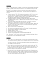
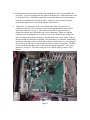
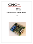
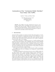
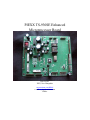
PIEXX TS-930SE Enhanced
Microprocessor Board
PIEXX, Inc.
XXX, New Hampshire
www.conknet.com/PIEXX
e-mail: [email protected]
Phone:
Introduction
This user manual will tell you everything you need to know about installing and using the
PIEXX TS-930SE enhanced microprocessor board. This breakthrough plug-in for the
Kenwood TS-930S transceiver allows you to use this excellent radio with modern
computer logging and radio control software. The main features of the enhanced TS930S are:
Computer control of VFOs, RIT and memories through a true RS-232 port (no level
converter required). Frequency and S-meter data provided to remote control or
logging software. Compatible with Kenwood RCP and all logging software packages
that support the standard Kenwood communications protocol.
99 additional memories, selectable by the RIT knob when the RIT is off and
VFO/MEMO button pressed. 8 additional switch-selectable memories store single or
split frequencies.
3-speed main tuning and selectable slow tuning rates – Fast QSY, yet two slow
tuning rates (2.5 and 10 kHz per revolution) for easy fine tuning.
Pre-settable initial frequencies on each band – no more lengthy retuning. During any
operating sessions, last operating frequency on each band retained for quick band
changes in contest situations.
RIT can be cleared while in Transmit mode.
RIT tuning by main tuning knob when D. LOCK pressed. Selectable tuning rates.
Extended transmit capability (e.g. MARS) optional.
Frequency display to 10 Hz.
500 KHz steps with the UP/DOWN keys.
Firmware user reprogrammable with optional programming cable.
Note: Because the TS-930S’s mode selection is done by hardware rather than software,
it is not possible to switch operating modes remotely.
Installation
1. Remove the top cover from the radio. If you are going to install the S-meter wiring
you will need to remove the bottom cover as well, but it is best to leave it on until you
are ready to do that step. This protects the signal unit board from damage while you
are working on the top of the radio.
2. Remove the four screws holding down the metal bracket with the speaker and VOX
controls. The original microprocessor board is located under this metal bracket. Lay
the speaker bracket over to the right side. There is no need to disconnect the wires
going to the speaker or the controls on this assembly.
3. Disconnect the 16 white cable plugs around the perimeter of the old microprocessor
board. Don't 'rearrange' the cabling. When you put the new board in, the cables will
more or less fall into position. The connectors on the new board are arranged in the
same order and orientation as those on the old one.
4. Remove and discard the old battery holder from the top of the speaker bracket. The
wiring for the battery, plug #3 on the old microprocessor board, is no longer used.
Batteries are not needed to maintain the memories on the new microprocessor board,
and eliminating them means getting rid of one source of possible damage to your rig
(batteries can leak!).
5. Remove the 6 screws that hold the microprocessor board in place. Remove the old
microprocessor board. You will not need it.
6. Remove the 4 screws that hold the microprocessor base plate (Figure 1) on top of the
phased locked loop (PLL) assembly. Remove the plate and mount the 6 (provided)
standoffs in the holes where the microprocessor board’s mounting hardware was
previously. Because the original mountings used metric hardware, you will need
either to tap these holes with a 4-40 tap, but you can drill them out and use the
provided nuts if you wish. The ground for the microprocessor board is made through
this hardware, so be sure that the standoffs are tight. Also, make sure you use the
lock washers.
Figure 1
7. Remount the microprocessor base plate. Again, make sure to get the hardware tight.
If there is any sign of corrosion on this plate, make sure you clean it off before
remounting.
8. Mount the new microprocessor board on the standoffs you have just installed in the
base plate. If you are looking from the front of the transceiver, small transformer will
be in the back left. It should be impossible to misinstall the board, as the mounting
holes are not symmetrical from left to right. Again, be sure to use the provided
lockwashers between the screw heads and the circuit board.
9.
Replace the 15 connectors on the circuit board (Note: there are now only 15
connectors, instead of 16, because you removed and discarded the battery and its
associated connector, in step 4). The connectors should be approximately in
alignment with the new board and in the correct orientation. Make sure that the
connectors are not plugged in so as to miss a pin. There should be no visible pins
after you plug in the mating connectors. Double check your work! Figure 2 shows
the board with all connectors reinstalled. Note that there is a connector with nothing
attached in the bottom center of the board as shown, and that there is a wire plugged
into a jack in the left center of the board just below the large electrolytics. The latter
is J20, and the picture shows the s-meter hook-up already completed – we’ll get to
that below, in step 14. The other open jack is for a future option, so don’t worry
about it.
Figure 2
10. You should notice that pin one of each connector is the pin closest to the appropriate
'J' reference number silk-screened on the microprocessor board. Make sure that there
are no wires in the J8 pin 1 and J6 pin 2 connector positions. If there are wires in
these positions, you need to find out why, because something’s not right.
11. Please make sure you have double-checked the installation of the connectors. If all is
well, you can power up the transceiver and check its functions. NOTE, unless the
speaker bracket is grounded, the VOX and Calibrator circuitry will not function
properly, so it is a good idea to make sure the front panel VOX button is in the out
(MANUAL) position until you’ve reinstalled the speaker and VOX control assembly.
12. At this stage, you may discover that the main tuning dial of your transceiver is tuning
in the opposite direction from before – i.e., clockwise rotation will decrease
frequency rather than increasing it. This occurs because certain TS-930Ss have a
subtle wiring change that causes this reversal when the PIEXX board is substituted.
Fortunately, the solution is simple. Locate the 4-pin connector J4 in the middle rear
of the microprocessor board (seen from the front). Reverse the two middle wires,
which are the channels A and B leads from the encoder on the main tuning dial.
DON'T just reverse the plug direction because the outside leads on J4 are power and
ground! To reverse the wires, take a tiny screwdriver or other probe and insert it
through the tiny window on the side of the plug next to the wire you want to remove.
Press it in gently and pull gently on the wire, and it should come out of the plug with
the terminal attached. Do the same with the other wire, reverse them, and push them
back into the plug till they snap into place. Reinstall the plug on J-4 and all should be
well.
13. To install the S-meter function, remove the bottom cover of the radio at this time.
14. Install the 10 pin header cable on connector J20 on the microprocessor board. This
connector only has 2 wires connected to it, and only one of these is used. Route these
wires through the opening in the front left of the radio, near the power switch, down
to the signal unit side of the chassis. Connect the lead with the heatshrink tubing on it
to the blue wire on signal unit connector 21 pin 9, which connects to the radio’s Smeter. Connector 21 is located on the back right side of the signal unit board as
viewed from the front of the radio.
15. Reinstall the bottom cover.
16. Plug the serial cable (provided) into modular jack J17 on the microprocessor board
(the smaller of the two telephone-type jacks). You can route this cable through the
access cover in the top of the radio that is provided for the VOX and calibrator
controls, or you may want to figure out a way to route it through the back of the set.
17. Reinstall the speaker bracket, being careful not to pinch any wires under the bracket.
Again, ground connections for the VOX and calibrator controls are made through the
mounting screws for this bracket, so clean up any corrosion and make sure the screws
are securely tightened.
18. Reinstall the top cover. Connect the serial cable to a communications port on your
computer, and you’re ready to enjoy computer control and other enhancements to the
operation of your TS-930S.
General Operating
Basic (i.e. non-computer-controlled) operation of the TS-930SE is almost identical to the
original TS-930S. There are a few changes:
The main display now reads out to 10 Hz (i.e. 2 decimal places to the right of the
decimal point, rather than 1. The main display no longer changes when the RIT is on
and tuned away from the original frequency.
The DOWN and UP buttons at the bottom of the BAND keyboard now command 500
KHz steps rather than 1 MHz as before. Also the start frequency on each band at
power-up can be set to fit your operating preferences – for example, you can start at
28.300 MHz if you prefer phone, or 28.000 if you like CW. To load these band-start
frequencies into memory, turn the MEMORY CH switch to channel 8. Tune your
transceiver to the first desired band-start frequency (in any legal ham band). Press
the MIN button. The band-start frequency is loaded into memory. Switch bands to
verify that it has been stored. Repeat the process for each band-start frequency in
turn.
The main tuning dial now has 3 tuning rates, depending on how fast you turn the
knob. The slowest rate can be either 2.5 or 10 kHz per knob revolution, selected by
the DIM/NOR switch (depress the switch for the standard 10 kHz rate). When you
turn the knob at a sustained higher speed, the frequency changes faster, up to about
100 kHz per revolution, which permits very rapid QSY from one band-edge to the
other.
When the D. LOCK button is depressed and the RIT is on, the main tuning knob
tunes the RIT. The DIM/NOR switch affects the tuning rate in this mode, as above.
The RIT can now be cleared while in Transmit.
When the RIT is tuned, the main frequency display does not change, so the actual
frequency is shown by the main display, +/- the offset amount.
You will not hear a relay click when you pass a band edge, but transmitting is still
disabled unless the MARS option is installed.
Memory Functions
The enhanced microprocessor board adds 99 user-settable memories to the 8 memories
provided by the original TS-930S (memory 8 on the MEMORY CH switch is now
reserved for band-start frequency settings). These added memories are accessible using
the RIT knob while the RIT is off. Turn the knob in either direction, and memory
frequencies 01-99 (clockwise) or 99-01 (counterclockwise) appear in sequence on the
display where the RIT offset value is normally seen. The procedure for loading
frequencies into these memories is the same as for the original 8 memories – turn to the
desired memory and press the MIN button. To control the transceiver with these
memories, press the VFO/MEMO button, as before, or press MR to retrieve the stored
frequency while leaving the main tuning dial in control. To use RIT on a memorycontrolled frequency, press the RIT button, and tune the RIT offset normally. The
memory channel in use can no longer be seen, but the orange “MEMO” label on the
display will remind you that you’re on a memory frequency (and, of course, the main
tuning knob won’t affect the frequency).
To use the original, switch-selected memories, press the CLEAR button with the RIT off.
You will note that the memory number controlled by the RIT knob will disappear, and a
smaller digit will appear next to the “RIT” label on the display. This is the original
memory channel indicator, and tracks with the MEMORY CH switch. The MIN and MR
buttons work as before, with the exception of memory 8, now used for the band-start
frequency selection. As an added feature, if you are operating split frequency and press
MIN, both the VFOA and VFOB frequencies are stored.
Computer Communications Details
The enhanced microprocessor board has a genuine RS-232 port (no level converter or
additional chips required) and supports a subset of Kenwood’s standard instruction set. It
has been exhaustively beta-tested with Kenwood’s RCP for the TS-570, DX4WIN 3.05,
CT 9.38, and TRLog 6.36, and should work properly with any other software that uses
the standard instruction set.
The implemented communications instructions are listed below. In all cases, the 2-letter
instruction, sent from the computer without a following parameter, is read by the
microprocessor board as a query. In response, the transceiver then reports its current
status. For example, if the computer sends FA, the radio will reply FA[frequency].
The one exception is the operating mode, because the mode (TUNE/CW/USB/
LSB/AM/FSK) is controlled by hardware in the TS-930S. In response to an IF query, the
microprocessor returns the mode information last sent to it by the controlling software,
unless the radio is in FSK mode, in which case it reports that fact to the computer.
The following instructions are supported by the TS-930SE microprocessor:
AI - Auto Information. If the parameter passed is 1 or 2, the uP will send SM and IF
information twice a second. AI0; disables the sending of automatic information
DN- Same as pressing the Microphone Down button
FA- Sets the frequency of VFOA. For example, data format for a frequency of
14.250.000 is FA00014250000;
FB- Sets the frequency of VFOB.
FR- Reads the receive frequency mode, 0=VFOA, 1=VFOB, 2=Memory
FS- Fine Step. If the parameter passed is 1, i.e. FS1, pressing the microphone up/down
keys will increment the frequency in 10Hz steps. FS0 forces 100Hz steps. The radio
powers up in the 10Hz step mode.
ID- Identification. The system reports 018, the same as a TS-570
IF- Reads the transceivers status
MC- Memory channel. Sets or reads the memory channel
MR- Memory read. Displays the frequency of the specified memory channel.
MW- Memory write. Sets the frequency of a specified memory channel.
PS- Power switch. PS1; sent on power up, PS0; sent on power down.
RC- RIT clear.
RD- RIT down, decreases the RIT frequency.
RT- RT1; enables the RIT function, RT0; turns it off.
RU-RIT Up, increases the RIT frequency.
SM- Displays the current S-Meter reading
UP- Same as pressing the Microphone UP button
VFOA, VFOB and Memory mode.
Some things to try with the serial port:
You can create a text document of commands and send them to the transceiver via
procomm (DOS) or Hyperterm (WIN9x). A good reason to do this is to load the memory
from a text file. Here are some sample lines from a frequency.txt file:
mw1 0100000990000;
mw1 0200001020000;
mw1 0300001030000;
mw1 0400001100000;
mw1 0500003885000;
mw1 0600005975000;
mw1 0700014263000;
mw1 0800027185000;
mw110800014263000;
mw110900027185000;
This loads memory locations 1-8 plus the power-up VFOA and VFOB. The memory map
for the microprocessor board is as follows.
1-99 Memory locations 1-99
100-107 Switch memory locations 1-8
108 Power-Up VFOA
109 Power-Up VFOB
110 1.5 mHz default value, this is the frequency that is selected with the 1.5 band switch
111 3.5 mHz default value, this is the frequency that is selected with the 3.5 band switch
112 7.0 mHz default value, this is the frequency that is selected with the 7.0 band switch
113 10 mHz default value, this is the frequency that is selected with the 10 band switch
114 14 mHz default value, this is the frequency that is selected with the 14 band switch
115 18 mHz default value, this is the frequency that is selected with the 18 band switch
116 21 mHz default value, this is the frequency that is selected with the 21 band switch
117 24.5 mHz default value, this is the frequency that is selected with the 24.5 band
switch
119 28 mHz default value, this is the frequency that is selected with the 28 band switch
120 29 mHz default value, this is the frequency that is selected with the 29 band switch
Here is a link to the Kenwood FTP site where you can download the Radio Control
Program for the TS-570. This program works well with the TS-930SE microprocessor
board.
ftp://208.197.91.81/e%3A/kenwood/kenftp/kenwood/Amateur/RCPsoftware/