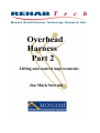
1
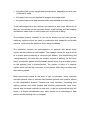
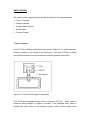
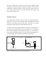
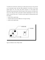
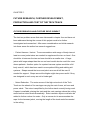
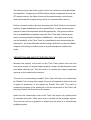
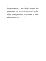
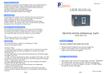
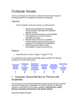
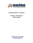
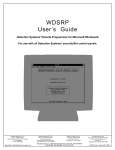
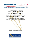
REHAB Tech- Monash Rehabilitation Technology Research Unit assume no liability for any
claim of adverse effects resulting from misapplication of the information presented here in.
While every effort is made to ensure the accuracy of the guide no responsibility or liability
will be taken for any inaccuracies.
REHABTech is finance and supported by
In collaboration with
© Copyright 1998
All rights reserved. No part of this publication may be reproduced or transmitted in any form
or by any means, electronic or mechanical, including photocopy, recording or any information
storage and retrieval system, without permission in writing from the publisher.
Requests for permission to make copies of any part of the work should be addressed to:
REHAB Tech- Monash Rehabilitation Technology Research Unit
C/- C.G.M.C.
260 - 294 Kooyong Road
CAULFIELD VIC 3162
AUSTRALIA
Email [email protected]
CHAPTER 1.
INTRODUCTION
Loosing the ability to walk or to support ones own weight has a strong impact
on a persons life and forces a drastic change of lifestyle upon them. A loss of
mobility creates numerous problems and usually leaves the effected person
less self sufficient and more dependant on others. Therefore gait re-education
must be a major part of the rehabilitation process after an injury which results
in the loss of walking ability.
The three main groups of patients in need of gait re-education are spinal cord
injured patients, hemiplegic (stroke) patients and lower limb amputees.
Although the causes for these locomotion disabilities differ, some problems
are universal, including reduced balance and inability to bear ones full weight.
Therefore weight bearing and the support of a patient in an upright position
are crucial factors, to allow for rehabilitation to take place. Traditionally, this
has been achieved by using parallel bars and assistive devices such as a
walking frame. However, there are problems associated with these devices;
the amount of weight relief cannot be controlled or monitored, upper body
strength and control have to be sufficiently available and a considerable risk
of falling is involved. 1
Recently various types of overhead harness support systems have started to
come into use with which the problems encountered with traditional assistive
devices can more or less be overcome. The patient dons a harness which is
attached to a frame that holds them in an upright position. There are several
advantages compared to other assistive devices such as parallel bars:
•
weight relief can be controlled and monitored and slowly decreased as gait
re-education progresses
•
the patient has a more upright and natural stance, depending on what type
of harness is used
•
the upper limbs are not required for support and weight relief
•
the patient cannot fall and therefore feels less inhibited and more secure
These advantages allow the clinician and patient to work more efficiently as
they can concentrate on the important factors of gait training such as stepping
and balance rather than on other areas such as the risk of falling.
The harness systems currently in use can be divided into two main groups:
stationary systems which are used in combination with treadmills and mobile
systems which allow the patient to move along a walkway.
The stationary systems are advantageous for patients with spinal chord
injuries as the problem is neurological. The treadmill forces the legs to move
at a certain speed producing a continuos gait pattern, thus familiarising and
“reprogramming” the brain with the complex actions of walking. On the other
hand, an amputee patient would probably benefit more from a mobile system
as the problem here is biomechanical. The system is more of a passive
system which follows the movement of the patient while they can determine
their walking speed.
Most experiences made in the area of gait re-education using overhead
harness systems seem to indicate that harness systems have positive effects
on the rehabilitation process. Patients are more confident, increasing their
walking speeds and stride lengths and medical professionals have more
precise and focussed methods to work with. It can be assumed that this will
result in a shorter rehabilitation time which would be an advantage to both
patient and the treating clinic or hospital.
CHAPTER 2.
DESIGN OF THE ORIGINAL HARNESS SYSTEM
BACKGROUND
To assist with and study different aspects of gait reeducation of patients with
lower limb disabilities (mainly amputee patients) at Monash Rehab Tech,
Melbourne, an overhead harness system, now called the Tech Track, was
designed. The design incorporated the use of a force plate and a walkway
already installed in the Rehab Tech biomechanics Laboratory.
To produce a system that would successfully deal with the problems faced by
patients and hospital staff during gait reeducation and rehabilitation, three
main aspects were considered while designing the Tech Track: 2
•
Safety
The system needed to guaranty that the patient would not be able to fall,
but be kept in an upright position at all times of use. This would allow
the patient and the user to concentrate on walking technique rather than
being concerned with stability and balance.
•
Walking assistance
The system needed to enable the patient to walk as normally and
unrestricted as possible while being given as much support as needed.
•
Weight bearing
The system needed to be able to provide a controllable amount of weight
relief to the patient.
BASIC DESIGN
The design of the original system can be devided into five separate parts:
•
Track / Carriage
•
Patient Harness
•
Weight Relief System
•
Motorisation
•
Control System
Track / Carriage
For the Track a hollow profile tube was chosen (Figure 2.1), which was then
bolted to beams in the ceiling of the laboratory. This type of Track is widely
used for hoists and conveyors and best suited the purpose at the time.
Figure 2.1 Track and Carriage Configuration
The Track and carriages chosen have a rating of 650 kg,2
which gives a
sufficient safety margin to support a person. Two carriages were used to
support the main frame of the harness system, while several others were
used to carry power cables and the compressed air hose for the pneumatic
weight relief system (Figure 2.1).
Patient Harness
Three main elements of a patient harness were originally considered to give
adequate support and carry the patients weight without undue discomfort and
obstruction to gait (Figure 2.2).
CROTCH
LOOPS
SHOULDER
LOOPS
Figure 2.2: Elements of a Patient Harness for Weight Relief
CHEST
AND/OR
WAIST
STRAPS
2
The harness also needed to be detachable from the rest of the system to
allow the patient to don and remove the harness while standing or in a
wheelchair 2. To allow for this, the harness consists of two parts: the upper
part, which is attached to the system via a rope and the jacket, which is worn
by the patient. The parts can be easily separated by the two shoulder clips
(Figure 2.3 patient harness).
Figure 2.3 patient harness
After trials revealed that a harness with crotch loops impeded walking
considerably, a waistcoat design was chosen for the jacket. With this harness
configuration the patient’s weight is carried by padded sections under the
arms, several straps across the chest and waist area and a larger strap
around the pelvis (Figure 2.3).
Weight Relief System
A pneumatic system attached to the frame of the main carriage allows for an
upward force to be set, which is then kept constant, regardless of the vertical
movement of the patient during the gait cycle. This allows for a precise
percentage of weight relief to be selected and held at all times.
The system functions by supplying constant air pressure to one chamber of a
pneumatic actuator and leaving the other open (Figure 2.4 a). This keeps the
force constant, regardless of which position the piston is in. The pressure is
set by turning the regulator (Figure 2.4 b) which sets the relay regulator to a
corresponding pressure of the desired percentage of weight relief.
a)
PRESSURIZED AIR
b)
REGULATOR
CONSTANT
PRESSURE
2
T-JOINT
ACTUATOR
CONSTANT FORCE
RELAY REGULATOR
Figure 2.4 Function and set up of the pneumatic system
2
The actuator is located in a horizontal position under the main frame of the
carriage. Attached to the piston is a rope, which runs through a pulley and
hangs down from the system is attached to the upper section of the patient
harness
Motorisation
The Tech Track is powered by a 0.75 kW permanent magnet motor with a
base speed of 1750 rpm and an armature voltage of 180 V DC. The speed of
the motor is reduced by a gearbox with a 5:1 ratio. Attached to the motor is a
drive wheel, which runs along the outside of the rail (Figure 2.5). The drive
wheel has a Diameter of 100mm. This allows for the carriage to travel at a
maximum speed of 6.5 km/h which is a sufficient speed for the use of the
harness. A wheel on the opposite side of the rail adds stability and can be
adjusted to give the driving wheel an adequate amount of Traction. 2
Figure 2.5 Motorisation of the system
As can be seen in Figure 2.5 the motor and gearbox have been attached
diagonally under the main carriage. This places the centre of gravity of the
motor and gearbox directly under the centre of the rail and carriage so as not
to over balance the system to either side.
Control System
The motor speed is controlled by a regenerative-type control, capable of
operating a DC motor in a bi-directional, which offers much better
controllability than a standard unidirectional speed control.3 The control is
situated in a box with a control panel fitted to the wall of the biomechanics
laboratory. The control panel consists of the following controls:
• Power on/off
• Emergency Stop
• Motor Start
• Motor Stop
• Motor Speed Control
• Auto/Console (switches the motor speed control between the manual
control on the console and the control on the carriage which allows the
carriage to follow the patient automatically)
The speed control on the carriage is achieved by a potentiometer mounted at
the axis of the pulley through which the rope runs. This returns a signal
proportional to the angle between the vertical and the rope, determining the
position of the patient in regards to the carriage above (Figure 2.6).
angle
Figure 2.6 Automatic Speed Control
2
The potentiometer sends a velocity request signal directly to the motor
controller. The signal from the potentiometer is amplified to allow for the angle
of the rope not to become too large before the motor responds. The amount
of amplification can be adjusted in the control box so that the speed response
of the system can be adjusted to specific needs. Acceleration, deceleration,
offset and gain can be adjusted directly on the controller.
2
CHAPTER 3.
SUGGESTIONS OF IMPROVEMENT AND FURTHER
DEVELOPMENT
To evaluate the feasibility of the overhead harness system for gait reeducation a study was conducted in 1996. It involved a number of below knee
amputee and able bodied subjects. The subjects walked along the walkway in
the Rehab Tech biomechanics laboratory using the Tech Track. The effects
of wearing the harness and of weight relief on individual gait patterns were
studied. Various parameters such as walking speed, stride length and ground
reaction forces were measured. The author of the study states the following
conclusions:
“The harness system has both positive and negative effects on
amputee gait and must, therefore, be viewed cautiously in relation to
amputee rehabilitation.
feedback
after
using
Although most subjects gave favourable
the
system,
further
improvements
and
investigation are required before its adoption as a clinical tool in
amputee rehabilitation.
It is the opinion of the author that, when
compared to parallel bar training, the overhead harness system does
not offer enough substantial improvements to warrant its future
utilisation in the rehabilitation of lower limb amputees.
As an
alternative, its merits are not strikingly great, but its disadvantages
would not seem to disqualify it either.
Nevertheless, such a system could be used in the case of ‘difficult’
patients. Some examples of the types of patients that may benefit from
the use of such a system are:
1) the obese;
2) the non-compliant;
3) those with high tissue breakdown susceptibility;
4) those with abnormally poor balance; and
5)
those with upper body or upper limb weakness (ill-suited to parallel
bars). “ 1
After reviewing the results of the study and coming to this conclusion, the
author does go on to state the following:
“Design modifications and further investigation should take place.”
1
Resulting from this study and several brainstorming sessions held with staff
at Rehab Tech numerous problems were stated and suggestions for
improvement and further development of the overhead harness system were
put forward. Five main problem areas were identified:
1. There was no lifting and height adjustment system, which made adjusting
of the height of the harness very complicated. To change the height the
rope needed to be untied and then retied at the desired position. the
patient also needed to be able to stand upright to done the harness and
while the height was adjusted.
2. The controls were not very user friendly as the control panel was situated
on a wall at one end of the walkway. This would not allow the clinician to
control the system and work with the patient at the same time. Not only
was it felt to be a hindrance but also a safety hazard, since the controls
were not quickly accessible if the clinician was working with the patient. To
operate the system safely, two people would be needed at all times.
3. Although the Tech Track was motorised all the subjects of the study felt
that they were pulling the system. This feeling increased as weight relief
was increased.
4. The harness jackets were difficult to adjust and uncomfortable for many
subjects, especially females. It was stated that several more than the
available two jacket sizes were needed to suit different body sizes.
5. The level of noise produced by the system, especially at greater walking
speeds was felt to be excessive and not appropriate for a clinical setting.
These areas needed to be addressed to make the Tech Track more user
friendly and feasible for use in a clinical and rehabilitation setting.
It was decided that all five problem areas would be looked into, but that this
project would deal conclusively only with the first two areas. If time permitted
the third area would also be considered. These problem areas are:
1. Lifting and Height Adjustment
2. Controls
3. Dragging of the System
CHAPTER 4.
HARNESS HEIGHT ADJUSTMENT AND LIFTING SYSTEM
DESIGN CRITERIA
To develop a lifting system for the Tech Track the following criteria had to be
considered:
• The lifting distance needed to be at least 0.7m, which was considered to
be sufficient to lift a person from a sitting to a standing position.
• The lifting speed needed to be sufficiently controllable so as not to cause
sudden jerking or other erratic movements while a person was in the
harness.
• The system needed to be able to lift at least 150 Kg to account for heavy
patients and give an adequate safety margin.
• The system was not to interfere with the movement or control of the
pneumatic weight relief system.
• Preferably, the system needed to fit within the overall dimensions of the
main carriage.
DESIGN OPTIONS AND INITIAL IDEAS
Systems Available on the Market
Initially several systems for lifting and transferring people that are available on
the market were considered and compared. The advantage of such a system
would be that the finished product could be purchased and no design or
production work needed to be done.
After initial research the electrically powered systems available were
considered not to be feasible as they would have needed major modifications
to be incorporated into the Tech Track system. It would take as much time
and ultimately cost less to design a new system.
Two lifting devises that were considered more closely were the Freedom Lifter
System produced by Laylah and the Self Aid Lifting System produced by
T.R.E.C. Both systems attach to the end of the harness rope and would
replace the top part of the harness. The harness jacket would clip on to the
lifting devices. Each consists of a hoist that is powered by rotating a handle.
Both hoists cost about $600 - 700. This was a negative factor, as there would
not be much more cost involved in designing and building an electric hoist
system.
The obvious disadvantage of these systems was that they were powered
manually. Because such a hoist would be positioned above the patients head
it would have been extremely difficult if not impossible to operate with the
patient in a standing position. These systems are designed to be used with a
harness that holds the user in a sitting position, thus allowing easy access to
the operating handle.
Another option that was considered was using an industrial hoist or winch
system. Several companies were contacted and information on available
systems collected. Unfortunately most hoists that are available on the market
for industrial use were not suited for various reasons such as dimensions,
weight, load rating or price.
One system that was considered closely was the DC 2000 from Ateco
Automotive Equipment. This is an electric DC planetary hoist used for off road
and military vehicles. It’s over all dimensions are such that it would have been
relatively uncomplicated to mount onto the Tech Track system. It is rated to
lift 900 kg, which is much more than needed.
The decision was made against the DC 2000 for several reasons: it was too
heavy duty for this application, it was relatively noisy, it was costly ($ 1575.00)
and it would have needed and extra power supply of 12V DC.
Having decided not to use a ready made hoist available on the market several
design options remained. there were two basic approaches to the problem of
height adjustment and lifting. One was to use a linear actuator simular to the
one used for the weight relief system. The other was to use a winch on which
the rope was rolled up.
One of the main design problems was that either the lifting or the weight relief
system would have to be attached to some kind of trolley and move back and
forth with the other system unless both could be achieved by one system.
The linear actuator could either be electrically or pneumatically powered and
would be mounted horizontally along the main carriage.
CHAPTER 5.
TECH TRACK CONTROL SYSTEM
CHAPTER 6.
USER MANUAL
BASIC COMPONENTS AND FUNCTIONS OF THE TECH TRACK
The Tech Track consists of several components as shown in
Figure 6.1.
Figure 6.1 Tech Track Components
1. Rail
3. Carriage Motor
2. Main Carriage Frame
4. Winch / Hoist System
5. Pneumatic
Weight
Relief
7. Automatic
Speed
System
Rope Guide
6. Control Box
8. Patient Harness
Control
/
The patient harness is attached to the winch system by a rope which runs
through a pulley and the rope guide on the main carriage frame . The winch
system raises and lowers the patient harness. It is connected to the
pneumatic actuator of the weight relief system and moves with the actuator.
The weight relief system allows for a percentage of weight relief to be set,
which is then kept constant regardless of the vertical displacement of the
patient during gait.
The main carriage runs along the rail attached to the ceiling of the
biomechanics laboratory. It is powered by the carriage motor which can either
be controlled manually or by the automatic speed control. The automatic
speed control measures the angle of the rope guide and sends a
corresponding signal to the motor controller in the control box. This increases
and decreases motor speed accordingly, keeping the main carriage above the
patient.
REMOTE CONTROL UNITS
The Tech Track has been designed to be controlled with a remote control.
This allows the clinician to assess patient gait and posture from any position
while easily making any necessary adjustments to the system. While all
controls have been designed to be fool proof and offer maximum safety for
the patient, it is vital that users familiarise themselves with the function of all
controls and safety features of the system before use.
The Tech Track can be controlled either by the RF remote control unit or by
the hand held wire remote control unit located in the clip at the side of the
control box. When the wire remote control unit is detached from its clip, it is
automatically switched on and the RF unit is switched off. The reverse occurs
when the unit is returned to the clip. Both units control the same functions but
have slightly different controls due to the fact that the RF remote control unit
cannot transmit analog signals.
The panels of both control units are depicted in Figure 6.2.
Figure 6.2 Remote Control Unit Panels
CONTROL FUNCTIONS
•
Power On / Off
This switch is located on a panel attached to the wall at one end of the
Track. The panel also includes an Emergency Stop button.
•
Motor Start / Stop
These push button controls start and stop the motor.
•
Speed Control
On the wire remote control unit this control is a dial which increases
forward or reverse motor speed depending on which direction it is turned.
On the RF remote control unit this control consists of three buttons.
Pushing the left or right button increases motor speed in either direction.
The middle button sets the speed to zero.
•
Auto / Remote
This switches between controlling the motor speed manually with the
remote control or with the automatic speed control corresponding to the
walking speed of the person in the harness.
•
Winch / Carriage
Depending on the status of this switch the controls either control the winch
motor or the carriage motor.
•
Stumble On / Off
This control is a safety mechanism to prevent the carriage from moving
when the patient stumbles or falls forwards or backwards. If the stumble
safety is on, the motor is automatically switches off when the pneumatic
actuator of the weight relief system is fully extended. When this occurs the
actuator needs to be retracted several centimetres and the “Motor Start”
button pressed to start the motor again.
INDICATOR PANEL
Since the “Auto / Remote” , “Winch / Carriage” and “Stumble On / Off”
controls on the RF remote control are toggled by pushing a button the status
of the switches is not always clear. An indicator panel has been mounted at
the bottom of the control box on the main carriage frame to show the switch
status when a control is activated. The panel is shown in Figure 6.3. The
number of stars “ * “ indicates the number off LED flashes showing the status
of a switch. For example; when the “ Auto / Remote” control is switched to
“Auto” the LED will give three quick flashes. When it is switched back to
“Remote” the LED will give one quick flash. A note of this has been made at
the bottom of the control panel on the RF unit ( Figure 6.2).
Figure 6.3 Switch Status Indicator Panel
It is advised when using the RF control to check the status of each control at
the beginning of use before activating “Motor Start”.
CONTROL SAFETY FEATURES
Switching between motors while the motor is moving can be harmful for the
motor and dangerous for the patient. Safety features have been incorporated
in both units to ensure that switching between motors is not possible when
motor speed is not at zero. On the wire remote control unit a circular,
transparent panel covering the Auto / Remote and Winch / Carriage switches
is attached to the speed control dial allowing these switches to be switched
only when the speed control is at zero and the motors are not moving.
Activating the Auto / Remote and Winch / Carriage switches on the RF
remote control unit automatically stops the motor. The Motor Start button then
needs to be pressed to start the motor. Activating “Motor Start” also sets the
speed control to zero.
Although these safety features ensure that the motors will not be moving
when switched it is recommended always to activate “Motor Stop” before
switching.
To prevent the winch from continuing to rotate when the rope is fully wound
up, an automatic motor stop has been attached to the bottom of the rope
guide (Figure 6.4). The motor stop switch consists of a clear plastic disk
attached to two push buttons. When the rope is fully wound up, the disk at the
end of the rope just above the patient harness depresses the motor stop
switch, turning of the motor. To start the winch again the following steps need
to be taken:
•
switch off the reset button
•
lower the harness until the disks are no longer touching
•
switch on the reset button
Figure 6.4 Bottom View of Rope Guide
CHAPTER 7.
FUTURE RESEARCH, FURTHER DEVELOPMENT,
PRODUCTION AND COST OF THE TECH TRACK
FUTURE RESEARCH AND FURTHER DEVELOPMENT
The last two problem areas that were discussed in chapter four and have not
been addressed during the course of this project need to be further
investigated and researched. After some consideration and initial research
into these areas the author has several suggestions:
: Patient Harness / Jacket. To accommodate a wide range of body sizes at
least two more jacket sizes are needed to supplement the two on hand. One
should be in between the two and one should be a smaller size. A large
jacket with longer straps than the one on hand would also be useful for more
obese patients. Another option for a patent harness system would be a full
body overall, which has been used in some patient lifting and walking aid
systems. Straps around the torso and pelvic area could still be used if
needed for support. Straps around the thighs might also prove useful if they
are designed in such a way as not to hinder gait.
: Noise Reduction. The main source of the high noise level of the Tech
Track are the wheels of the carriages carrying the main frame, air hose and
power cable. The noise is amplified by the hollow track currently being used.
If space is available, placing the track and the main carriage above the ceiling
would reduce noise levels dramatically. Extra insulation layers could also be
added to further reduce the noise. Only a narrow slot to accommodate the
rope for the harness jacket, running the length of the track would be needed
in the ceiling.
The electronics circuits of the control units in the control box could be refined
and simplified. Designing one PCB board for all the components such as the
RF remote receiver, the relay drivers and the potentiometer control board
would eliminate the complex wiring, which is a common failure source.
Further research needs to be done comparing the Tech Track to conventional
methods of gait rehabilitation such as parallel bars. A study comparing two
groups of lower limb amputees would be appropriate. One group would be
set on a rehabilitation programe using the Tech Track and a similar group
would use conventional methods of rehabilitation. Only after such a study
can the feasibility of the Tech Track in a rehabilitation and clinical setting be
determined. the main difficulties will be finding a sufficient number of suitable
subjects and funding a clinician such as a physiotherapist to conduct the
study.
PRODUCTION AND COST OF THE TECH TRACK
Because the majority of the work on the Tech Track system until now has
been done as part of various student projects, design and development costs
have been relatively low. This will result in a cheaper price than comparative
systems on the market at the moment.
The cost of a commercially available Tech Track will have to be determined
by Rehab Tech. Among other things, the price will depend on how much time
is spent on production of the system by Rehab Tech staff. The costs of
contracting out parts of the production, such as construction of the Track, will
also play a part in the final cost of the system.
Apart from the construction costs of the Track, this report only quotes prices
of materials and parts, which were used or quoted for the prototype system.
They can be used as a guideline in determining the price of a commercially
available system.
Since customer preferences and needs will vary, prices for various available
options are quoted in Table 7.1. Table 7.2 consists of list of supplier names
and addresses with contact telephone numbers. These are suppliers of parts
for the modifications of the Tech Track done during the time of this project.
Suppliers for parts of the original system can be found in the report
“Motorised Overhead Harness Project” by Andrew Searle. The complete
budget of the modified Tech Track as set up in the Rehab Tech biomechanics
laboratory can be found in List
ITEM
SUPPLIER
unmodified harness system
See Budget for Unmodified System
QTY
PRICE / $
UNIT TOTAL
N/A
Total: 3308.00
W inch System for Patient Height A djustment
DC Motor and Gearbox
Reynolds Dynamics
Drive Shaft
Reynolds Dynamics
Bearings
Bearing Service
Aluminium Rod 100mm dia. x 100mm Caprol
Steel for Frame
Handyman Steel
bolts
rope
1
1
10
1
1
994.00
50.00
5.13
16.04
17.04
994.00
50.00
51.30
16.04
17.04
25.00
Total: 1153.38
Control System incl. W ire Remote Control
Case for Hand Held Controls
Contactor 12.5A 220 / 240V
1N/O&1N/C Aux. Block for Conactor
W iring / W iring accessories
Switches
Adaptor 3-12V DC
Relay DPDT 12DC
RS Components
RS Components
RS Components
Penhalluracks Building Supp.
Dick Smith Electronics
Dick Smith Electronics
Dick Smith Electronics
1
1
1
N/A
N/A
1
1
15.87
50.70
19.54
14.90
15.50
29.95
5.00
15.87
50.70
19.54
14.90
15.50
29.95
5.00
Total:
151.46
32.00
11.00
50.00
22.00
65.00
30.00
32.00
11.00
50.00
66.00
65.00
30.00
Total:
254.00
48.00
8.55
48.00
8.55
Total:
56.55
UHF Remote Control System
12 Channel UHF Transmitter
Case for Transmitter
12 Channel UHF Reciever
Relay driver kit
Digital potentiometer kit
W iring and Accessories
Oatley Electronics
Oatley Electronics
Oatley Electronics
Oatley Electronics
RS Components, Radio Parts
Dick Smith, Radio Parts
1
1
1
3
1
N/A
Accessories
Pneumatics Hose 10 mm dia. x 30m Genco Fittings
Case for W all Mounting of Power On/OffRS Components
1
1
Tota l Cost of Modifie d System: 4923.00
Table 7.3.
ITEM / OPTION
PRICE
Track (including construction costs) *
$2300.00
Basic Tech Track System (including supply wires and hose) *
$3520.00
UHF Remote Control System
$276.00
Hand Held Controls of Weight Relief System
$1050.00
UHF Remote Control of Weight Relief System
$1115.00
* Parts of these prices are taken from the budget of the unmodified system
Table 7.1 List of Item and Option Prices
SUPPLIER
ADDRESS
Reynolds
1B/310 Boundary Rd
Dynamics
Dingley, Vic 3172
Oatley
PO Box 89
Electronics
Oatley, NSW 2223
RS
8-10/45 Gilby Rd.
Components
Mt Waverley, Vic 3149
Dick Smith
613 Nepean Hwy.
CONTACT NAME
TELEPHONE
Neil McInnes
(03) 9551 6633
N/A
(02) 9584 3561
Bruce
(03) 9330 3666
N/A
(03) 9592 2677
N/A
(03) 9571 8244
N/A
(03) 9553 0642
N/A
N/A
East Brighton, Vic.
Radio Parts
1097 Dandenong Rd.
East Malvern, Vic
3145
Handyman
29 Nelbern Rd
Steel
Moorabbin, Vic
Penhalluracks
345 Hawthorn Rd.
Building
Caulfield Vic
Suppl.
Table 7.2 Suppliers List
ITEM
SUPPLIER
QTY
PRICE / $
UNIT TOTAL
unmodified harness system
See Budget for Unmodified System
N/A
Total: 3308.00
Winch System for Patient Height Adjustment
DC Motor and Gearbox
Drive Shaft
Bearings
Aluminium Rod 100mm dia. x 100mm
Steel for Frame
bolts
rope
Reynolds Dynamics
Reynolds Dynamics
Bearing Service
Caprol
Handyman Steel
1
1
10
1
1
994.00
50.00
5.13
16.04
17.04
994.00
50.00
51.30
16.04
17.04
25.00
Total: 1153.38
Control System incl. Wire Remote Control
Case for Hand Held Controls
Contactor 12.5A 220 / 240V
1N/O&1N/C Aux. Block for Conactor
Wiring / Wiring accessories
Switches
Adaptor 3-12V DC
Relay DPDT 12DC
RS Components
RS Components
RS Components
Penhalluracks Building Supp.
Dick Smith Electronics
Dick Smith Electronics
Dick Smith Electronics
1
1
1
N/A
N/A
1
1
15.87
50.70
19.54
14.90
15.50
29.95
5.00
15.87
50.70
19.54
14.90
15.50
29.95
5.00
Total:
151.46
32.00
11.00
50.00
22.00
65.00
30.00
32.00
11.00
50.00
66.00
65.00
30.00
Total:
254.00
48.00
8.55
48.00
8.55
Total:
56.55
UHF Remote Control System
12 Channel UHF Transmitter
Case for Transmitter
12 Channel UHF Reciever
Relay driver kit
Digital potentiometer kit
Wiring and Accessories
Oatley Electronics
Oatley Electronics
Oatley Electronics
Oatley Electronics
RS Components, Radio Parts
Dick Smith, Radio Parts
1
1
1
3
1
N/A
Accessories
Pneumatics Hose 10 mm dia. x 30m
Case for Wall Mounting of Power On/Off
Genco Fittings
RS Components
1
1
Total Cost of Modified System: 4923.00
Table 7.3 Budget of Modified System
1
Timothy Jarrot; Effects of Harness Supported Walking on
Able-Bodied Subjects and Lower Limb Amputees; Prosthetics and Orthotics,
La Trobe University;1996
2
Andrew Searle; Motorised Overhead Harness Project; Monash Rehab
Tech; 1995
3
KB Electronics, Inc.; KBRG Installation and Operation Instructions; 1992