1
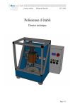
Gem Drive Safe Torque Off Manual gb Actuator INFRANOR GD1 GD1 – STO Manual WARNING This is a general manual describing a series of servo drives having output capability suitable for driving AC brushless sinusoidal servo motors. Please see GD1 User Guide for the operation of the drive (commissioning, configuration, …). Instructions for storage, use after storage, commissioning as well as all technical details require the MANDATORY reading of the manual before getting the drives operational. Maintenance procedures should be attempted only by highly skilled technicians having good knowledge of electronics and servo systems with variable speed (EN 60204-1 standard) and using proper test equipment. The conformity with the standards and the "CE" approval is only valid if the items are installed according to the recommendations of the drive manuals. Connections are the user's responsibility if recommendations and drawings requirements are not met. CAUTION Any contact with electrical parts, even after power down, may involve physical damage. Wait for at least 10 minutes after power down before handling the drives (a residual voltage of several hundreds of volts may remain during a few minutes). ESD INFORMATION (ElectroStatic Discharge) INFRANOR drives are conceived to be best protected against electrostatic discharges. However, some components are particularly sensitive and may be damaged if the drives are not properly stored and handled. STORAGE The drives must be stored in their original package. When taken out of their package, they must be stored positioned on one of their flat metal surfaces and on a dissipating or electrostatically neutral support. Avoid any contact between the drive connectors and material with electrostatic potential (plastic film, polyester, carpet …). HANDLING If no protection equipment is available (dissipating shoes or bracelets), the drives must be handled via their metal housing. Never get in contact with the connectors. ELIMINATION In order to comply with the 2002/96/EC directive of the European Parliament and of the Council of 27 January 2003 on waste electrical and electronic equipment (WEEE), all INFRANOR devices have got a sticker symbolizing a crossed-out wheel dustbin as shown in Appendix IV of the 2002/96/EC Directive. This symbol indicates that INFRANOR devices must be eliminated by selective disposal and not with standard waste. INFRANOR does not assume any responsibility for any physical or material damage due to improper handling or wrong descriptions of the ordered items. Any intervention on the items, which is not specified in the manual, will immediately cancel the warranty. INFRANOR reserves the right to change any information contained in this manual without notice. ©INFRANOR, June 2009, All rights reserved. Issue: 1.1 GD1 1 GD1 – STO Manual Content Page CHAPTER 1 – GENERAL DESCRIPTION............................................................................................. 3 CHAPTER 2 – SPECIFICATIONS.......................................................................................................... 4 2.1 - FUNCTIONAL DIAGRAM............................................................................................................. 4 2.2 - COMMAND SYSTEM CONCEPTION .......................................................................................... 4 2.2.1 - Safety instructions ................................................................................................................. 4 2.2.2 - STO connection ..................................................................................................................... 5 2.2.3 - Timings .................................................................................................................................. 6 2.2.4 - Performance level.................................................................................................................. 7 2.2.5 - Periodic inspection routines................................................................................................... 7 2.2.6 - Residual risk .......................................................................................................................... 7 CHAPTER 3 – CONNECTION EXAMPLE ............................................................................................. 8 3.1 - EXAMPLE 1: STOP CATEGORY 0 ACCORDING TO EN 60204-1 COMPLYING WITH EN13849-1 CAT. 3 ... 8 3.2 - EXAMPLE 2: STOP CATEGORY 1 ACCORDING TO EN 60204-1 COMPLYING WITH EN13849-1 CAT. 3 ... 9 2 Contentt GD1 – STO Manual Chapter 1 – General description Safe Torque Off (STO) definition according to the EN 61800-5-2 standard: "Power, that can cause the rotation of a motor (or displacement in the case of a linear motor), is not applied to the motor. The drive will not provide energy to the motor which can generate torque (or force in the case of a linear motor)". The STO function corresponds to an uncontrolled stopping in accordance with the stop category 0 of the EN 60204-1 standard. The STO function may be used where power removal is required to prevent an unexpected start-up. In circumstances where external influences (with vertical loads for example) are present, additional measures (mechanical brakes for example) may be necessary to prevent any hazard. The standard output of the drive must not be considered as a safe output. When using a mechanical brake, it will be mandatory to introduce a safe contact from an external device in the brake actuation line. The STO function cannot be considered as a safe insulation device for the motor. It does not prevent from any voltage on the motor terminal block. The integrated STO function fulfills the EN ISO 13849-1:2006 category 3 PLd requirements. PLd corresponds to SIL2, according to "Table 4 - Relationship between PL and SIL" of 13849-1 standard. Chapter 1 – General description 3 GD1 – STO Manual Chapter 2 – Specifications 2.1 – FUNCTIONAL DIAGRAM The "Safe Torque Off" function allows to keep the motor shaft free by avoiding the IGBT module commutation. This is achieved by means of two techniques: - IGBT command supply removal, - PWM removal. GEM DRIVE DSP PWM PWM POWER BOARD STO1/ EGND IGBT Module Drivers STO_OUT MONITORING Vcc EGND M +15V STO2/ EGND Different parts of the functional diagram are described below: • The green part is the first channel of the safety function. PWM signals are disabled by inhibiting the optocouplers commutation. • The blue part is the second channel of the safety function. IGBT gate signals are disabled by the power supply shut down. • The red part is the monitoring function which detects faults by comparing the two channel outputs. If a fault is detected this function locks both channels in safe state. • The black part is the functional part of the drive which is not used to achieve the safety function. STO_OUT output is the state feedback to facilitate the function integration. This output is not safe. It only has an informative function. 2.2 – COMMAND SYSTEM CONCEPTION 2.2.1 –SAFETY INSTRUCTIONS The integration of the STO function must be the result of a risk analysis of the complete machine. All control components must comply with the requirements of this risk analysis. Installing and commissioning of safety functions must be performed by skilled personnel only. Short-circuit avoidance: Install the drive in a control cabinet with a minimum IP54 protection. Avoid control signals proximity. Any short-circuit between two control signals must be detected: - - the short circuit will either be detected by the circuit-breaking system (fuse for example); in this case, the voltage reference is grounded, and shielded pair cables must be used (shield is connected to the ground), or ribbon cable with all unused wires connected to the ground to prevent proximity with hot potential signals or a short-circuit detection device must be integrated. Take care that, as the STO function performs the motor power removal without shutting down the power supply, electrical risks remain unchanged when the STO function is active or inactive. In applications with vertical axes, additional measures (mechanical brake) may be necessary. Refer to the EN13849-2 standard for any complementary information. 4 Chapter 2 – Specifications GD1 – STO Manual 2.2.2 – STO CONNECTION 2.2.2.1 - X2 Connector Weidmuller D 32 pins male Section: 0.25 mm2 (AWG22) X2 N° 19 20 21 SIGNAL +24V external GND external 23 STO2 26 STO_OUT STO1 DESCRIPTION External 24 V supply, wired if the STO_OUT output is used Voltage reference of the STO1/, STO2/ inputs, and STO_OUT output. Channel 1 input for the STO function inhibition High level releases the enabling Channel 2 input for the STO function inhibition High level releases the enabling Digital output for state feedback, non safe. During the installation, take care to avoid proximity between any STO signal and high potential. 2.2.2.2 - Specifications of inputs 3,3 V 8,2 kΩ Logic input 2,2 nF 100 kΩ 0V external These optocoupled inputs operate in negative logic. The input voltage corresponding to level 1 must be between 18 V and 30 V. 2.2.2.3 - Specifications of output +24V external +24V external 10 kΩ 330 Ω Driver 0V 0V external External supply +24 V (18 V < U < 30 V) Maximum voltage drop: 2 V Protection against overload Available output current per output (mA) Number of activated outputs / Cycle ratio (%) 2 4 Chapter 2 – Specifications 100 % 200 mA 100 mA 70 % 200 mA 150 mA 50 % 200 mA 200 mA 30 % 200 mA 200 mA 5 GD1 – STO Manual 2.2.3 – TIMINGS The STO function has an activation / release response time of 15ms / 2ms max. However, an additional delay of 6,5 ms after STO inputs are high is necessary before the enable/inhibit signal activation, as mentioned on the following chronogram: STO1/ t≤50ms STO2/ 25ms STO_OUT 1ms 15ms Drive state ready t>50ms t≤50ms 15ms 2ms Safe : Warning STO active displayed 0x3024,0.bit0 ready init safe 50ms STO fault, channels 1 & 2 locked 0x3022,1.bit4 0x3022,2.bit23 6,5ms A functional incoherence state between channels 1 and 2 is allowed during 50ms. The response time of the monitoring part is 100ms to 200ms. If the monitoring part detects incoherence between channel 1 and 2, it locks both channels in the safe state. The STO fault cannot be reset. This state can only be exited by shutting down the 24V power supply. At this moment, the user must find and solve the problem that caused this fault state. The STO function has two ways to check the state of the drive: the "STO_OUT" digital output, and objects fieldbus (STO active warning, STO channel 1 & 2 errors). All these state feedback are provided for informative purpose and cannot be used as safe information. ! Take care to automatic restart: When the STO function is disabled, the restart of the machine should only be possible by an explicit demand to prevent unexpected automatic restart. Take care to this point when the user program manages the drive start/stop. Used alone, the STO function corresponds to an uncontrolled stop in accordance with stop category 0 of the EN 60204-1 standard. So, this function is suitable to machines with low inertia or high resistive torque. When using high inertia or low resistive torque machines, the user should initiate a controlled stop. To achieve a controlled stop in accordance with stop category 1 of the EN 60204-1 standard, the control system of the machine must generate the following sequences: Deceleration of the load by means of the drive control, When the load is at standstill or almost, disabling the PWM. Finally, activation of the STO function. 1 STOP 0 Deceleration ramp is controlled by the drive SPEED 0 1 ENABLE PWM 0 24V STO1 STO2 6 0 Chapter 2 – Specifications GD1 – STO Manual 2.2.4 – PERFORMANCE LEVEL (1) The Safe Torque Off function fulfills category 3 /PLd requirements of the EN ISO 13849-1:2006 standard. PLd corresponds to SIL2 according to "Table 4 - Relationship between PL and SIL" of the EN ISO 13849-1:2006 standard. To achieve overall PL by combining safety related parts in series, refer to §6.3 of 13849-1 standard: SRP/CS1 PL1 SRP/CS2 PL2 PLLOW NLOW a >3 ≤3 b >2 ≤2 c >2 ≤2 d >3 ≤3 e >3 ≤3 D D D D D D D D D D D SRP/CSN PLN PL None, not allowed a a b b c c d d e NOTE The values calculated for this look-up table are based on reliability values at the midpoint for each PL. (1) See attached attestation of conformity in chapter 4. 2.2.5 – PERIODIC INSPECTION ROUTINES The well-working of the function needs to be checked at least once a year and during the validation of the machine safety functions. The goal of this procedure is to verify that all subsystems of the safety function are operational. The command system must integrate a checking mode reserved to an operator aware of potential risks due to a bad operation of the safety system. It is highly recommended that the operator signs a register in order to sensitize him. Step N° 1 2 3 4 5 6 Input STO1/ STO2/ STO_OUT 1 1 0 0 0 1 1 1 0 0 1 0 1 1 0 X X X State Motor Powered Free Powered Free Free X Description No fault is displayed. STO active warning is displayed. No fault is displayed. STO fault is displayed. STO fault is displayed and must be unresetable. Shut down of 24V power supply to reset STO fault At each step, the operator must verify that the motor provides or not torque, If the drive behavior is different from the one described in the table above, the drive must be replaced. 2.2.6 – RESIDUAL RISK In case of short-circuit between two power transistors, there is a residual risk of motor shaft rotation that can reach: 360° (2p: number of motor poles). 2p ! Take care of electrical risks, as the STO function performs the motor power removal without shutting down the power supply and there is no galvanic insulation. Chapter 2 – Specifications 7 GD1 – STO Manual Chapter 3 – Connection example Following diagram examples are given to make the integration of the safety function easier. The integration of the STO function must be the result of a risk analysis of the complete machine. 3.1 – Example 1: Stop category 0 according to EN 60204-1 complying with EN13849-1 cat. 3 Low inertia axis application / high resistive torque GD1-uuu/cc/PS-R X2 Example of inputs configuration See User manual 32 AOK+ 3 4 24 V Motor temp. Motor temp. 31 AOK1 IN1 (ENABLE) 2 IN2 (FC+) 19 20 Ext. reference 26 STO_OUT 21 STO1 23 2 24 Vdc power supply isolated from the 230 Vac mains 11 3 S2 S4 Resolver reference 5 4 R1 R2 GND X9 STO2 Motor brake + 1 Motor brake - 2 X10 CAN-L CAN-GND DC+ DC- +24 Vdc + 1 2 2 4 A UL listed GND brake 1 +24 Vdc brake X12 230 Vac single-phase 3 Power supply inside GND Phase 1 Neutral GND 2 OR 3 φ 400Vac 4 4 A UL listed + OTHER AXES GD1-uuu/cc/00-0 X11 CAN-H Auxiliary supply 24 Vdc +/-15% isolated MOTOR GND Phase 1 Phase 2 Phase 3 GND 4 Motor U phase 1 Motor V phase 2 Motor W phase 3 Brake supply 230 Vac Motor brake - 24 Vdc/1.5A + Other axes in multiaxIs X8 - AC S3 S1 10 X6, X7 1 2 3 4 5 6 7 8 9 RESOLVER TC TC Resolver signal IN3 (FC-) IN4 (Index) 24 V Ext. if logic outputs used X1 12 13 UL compliance only 3 X12 GND L1 phase L2 phase L3 phase 1 See UL fuses table Power relay UL compliance only GND Braking resistor 1 Braking resistor 2 X11 1 X11 1 2 2 2 Total power of the application < 4 kW in 230 V or < 7 kW in 400 V Mains 230 Vac single-phase 20A max. Mains 3x400V 2 3 4 Power relay See UL fuses table GND GND 10 20A max X11 1 External or internal braking resistor 2 Please note that the motor control must be disabled before activating the STO function. In the example, the digital input IN1 (enable) is used to disable the PWM control. A light is wired with STO_OUT output to inform the drive state. 8 Chapter 3 - Connections GD1 – STO Manual 3.2 – Example 2: Stop category 1 according to EN 60204-1 complying with EN13849-1 cat. 3 High inertia axis application / low resistive torque In the following diagram, only the STO integration is safe. The deceleration ramp is not safe according to EN13849-1 because it uses a common drive function. GD1-uuu/cc/PS-R Low resistive torque X2 24V Ext. S11 Motor temp. Motor temp. Example of inputs 32 AOK+ configuration 31 AOKSee User manual 1 IN1 (ENABLE) 2 IN2 (FC+) 3 IN3 (FC-) 4 IN4 (Index) 19 24 V Ext. if logic outputs used 20 Ext. reference 24V S21 S1 X1 12 13 RESOLVER TC TC 2 S3 S1 Resolver signal 10 11 3 S2 S4 Resolver reference 5 4 R1 R2 GND X9 S12 S22 Y6 Y7 P1 Motor brake + 1 Motor brake - 2 Motor brake - 24 Vdc/1.5A + S21 X10 26 STO_OUT P2 21 STO1 PNOZ elvp 10s 23 STO2 S11 S34 P2 1 2 3 4 5 6 7 8 9 P1 Ext. Ref. 14 24 S21 Y5 24 Vdc power supply isolated from the 230 Vac mains AC 230 Vac 24 Vdc +/-15% isolated CAN-H 4 GND 3 +24 Vdc 4 A UL listed + + 2 4 A UL listed GND brake 1 +24 Vdc brake Phase 1 Neutral 2 GND 3 OR Other axes in multiaxIs UL compliance only X12 GND L1 phase L2 phase L3 phase 1 See UL fuses table 20A max Power relay UL compliance only GND Braking resistor 1 Braking resistor 2 X11 1 X11 1 X11 1 2 2 2 Total power of the application < 4 kW in 230 V or < 7 kW in 400 V Mains 230 Vac single-phase 20A max. Mains 3x400V 2 3 4 See UL fuses table GND GND 10 ! 1 2 X12 X8 - OTHER AXES GD1-uuu/cc/00-0 X11 DC+ DC- CAN-L CAN-GND Power supply inside S36 Y32 Auxiliary supply S35 X6, X7 Brake supply A2 MOTOR GND Phase 1 Phase 2 Phase 3 GND 4 Motor U phase 1 Motor V phase 2 Motor W phase 3 230 Vac single-phase Y4 3 φ 400Vac A1 Power relay External or internal braking resistor 2 For the installation of the safety relay, see PILZ PNOZ e 1vp manuals. See installation manual of the GD1 servodrives for the complete connection description. In the connection diagram example above, the PILZ safety relay orders the servodrive to decelerate by the ENABLE signal, and after a safety delay of 0.5 s, it activates the STO function of the drive. Note that the behavior of the servodrive on the ENABLE signal activation has to be setup in the appropriate mode (i.e. speed ramp deceleration) prior to any stop procedure. In this example diagram, the user does not need to use shielded cables because the PILZ safety relay detects short-circuits. The output used to generate the Inhibit/Enable signal does not need to be a safety one because only the STO function is safe according to EN13849-1 category 3. A light is wired with STO_OUT output to inform the drive state. Chapter 3 - Connections 9 GD1 – STO Manual Chapter 4 – Appendix 4.1 – ATTESTATION OF CONFORMITY After a deep analysis of the GD1 range, the CETIM (French Industrial and Mechanical Technical Center) third-party attests the compliance of the GD1 range with the EN954-1 and EN 13849-1 standards: 10 Chapter 4 - Appendix GD1 – STO Manual 4.2 – ORDER CODE GD1 – uuu / cc – PS – R – SI – Ex1 – Ex2 – Ex3 – 00 - RS Voltage: 230 or 400 Vac Peak current Power supply inside (00: without) Additional integrated braking resistor (0: without) Safety integrated: S1 = Safe Torque Off Extensions Ex1, Ex2, Ex3: Each extension slot can receive an extension board. Can be selected: One bus interface: PR = Profibus DP, I1 = additional input/output, EO = Encoder Output ET = Ethercat 00 = without 00 = reserved Serial link RS-422 integrated (00 = standard = RS232) Chapter 4 - Appendix 11