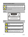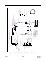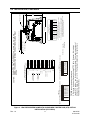
1
HDT0E000
HDT0E003
HDT0E00A
HD6 Nitrogen Pressurized Dome
Installation Manual
900.0725 – June 2006 - Rev. 1.0
ISSUE
DATE
REVISIONS
900.0697
1.0
December 2005
Initial Release
900.0725
1.0
Rev. 1.0
June 2006
Add installation drawings for fly-lead configuration; remove
drawings for 28-pin configuration; add ground connection to
14-pin connector configuration; Add IP66 rating; remove
Ultradome; change CAT5 to UTP; delete UTC; added 23x
color and 25x day/night camera models
ii
900.0725
21-June-06
FCC COMPLIANCE STATEMENT
INFORMATION TO THE USER: This equipment has been tested and found to comply
with the limits for a Class A digital device, pursuant to part 15 of the FCC rules. These
limits are designed to provide reasonable protection against harmful interference when
the equipment is operated in a commercial environment. This equipment generates,
uses, and can radiate radio frequency energy and, if not installed and used in
accordance with the instruction manual, may cause harmful interference to radio
communications. Operation of this equipment in a residential area is likely to cause
harmful interference in which case the user will be required to correct the interference at
his own expense.
CAUTION: Changes or modifications not expressly approved by the party responsible
for compliance could void the user’s authority to operate the equipment.
This Class A digital apparatus complies with Canadian ICES-003.
Cet appareil numérique de la Classe A est conforme à la norme NMB-003 du Canada.
USERS OF THE PRODUCT ARE RESPONSIBLE FOR CHECKING AND
COMPLYING WITH ALL FEDERAL, STATE, AND LOCAL LAWS AND
STATUTES CONCERNING THE MONITORING AND RECORDING OF
VIDEO AND AUDIO SIGNALS. HONEYWELL VIDEO SYSTEMS SHALL
NOT BE HELD RESPONSIBLE FOR THE USE OF THIS PRODUCT IN
VIOLATION OF CURRENT LAWS AND STATUTES.
Rev. 1.0
iii
900.0725
21-June-06
Rev. 1.0
iv
900.0725
21-June-06
IMPORTANT SAFEGUARDS
1.
READ INSTRUCTIONS – All safety and operating instructions should be read before the unit is
operated.
2.
RETAIN INSTRUCTIONS – The safety and operating instructions should be retained for future
reference.
3.
HEED WARNINGS – All warnings on the unit and in the operating instructions should be adhered
to.
4.
FOLLOW INSTRUCTIONS – All operating and use instructions should be followed.
5.
CLEANING – Unplug the unit from the outlet before cleaning. Do not use liquid cleaners or
aerosol cleaners. Use a damp cloth for cleaning.
6.
ATTACHMENTS – Do not use attachments not recommended by the product manufacturer as
they may result in the risk of fire, electric shock, or injury to persons.
7.
WATER AND MOISTURE – Ensure the pressurized dome is sealed so water and moisture cannot
penetrate the mount, the housing, or lower dome. The electronic pan and tilt device housed in the
dome cannot be exposed to water or moisture.
8.
ACCESSORIES - Do not place this product on an unstable cart, stand, tripod, bracket, or table.
The product may fall, causing serious injury to a child or adult and serious damage to the
equipment. Use only with a cart, stand, tripod, bracket, or table recommended by the
manufacturer, or sold with the product. Any mounting of the product should follow the
manufacturer’s instructions and should use a mounting accessory recommended by the
manufacturer. Wall or shelf mounting should follow the manufacturer’s instructions and should use
a mounting kit approved by the manufacturer.
9.
A product and cart combination should be moved with care. Quick stops, excessive
force, and uneven surfaces may cause the product and cart combination to overturn.
10.
VENTILATION - Slots and openings in the cabinet and the back or bottom are provided for
ventilation and to ensure reliable operation of the equipment and to protect it from overheating.
These openings must not be blocked or covered. The openings should never be blocked by
placing the product on a bed, sofa, rug, or other similar surface. Equipment should never be
placed near or over a radiator or heat register. This product should not be placed in a built-in
installation, such as a bookcase or rack unless proper ventilation is provided or the manufacturer’s
instructions have been adhered to.
11.
POWER SOURCES – This product should be operated only from the type of power source
indicated on the marking label. If you are not sure of the type of power supplied to your home,
consult your product dealer or local power company. For products designed to operate from
battery power or other sources, refer to the operating instructions.
12.
GROUNDING OR POLARIZATION – The power supply supplied with this unit may be equipped
with a polarized alternating-current line plug (a plug having one blade wider than the other). This
plug will fit into the power outlet only one way. This is a safety feature. If you are unable to insert
the plug fully into the outlet, try reversing the plug. If the plug should still fail to fit, contact your
electrician to replace your obsolete outlet. Do not defeat the safety purpose of the polarized plug.
Rev. 1.0
v
900.0725
21-June-06
IMPORTANT SAFEGUARDS, CONTINUED
13.
OVERLOADING – Do not overload outlets and extension cords as this can result in a risk of fire or
electric shock.
14.
POWER-CORD PROTECTION – Power supply cords should be routed so that they are not likely
to be walked on or pinched by items placed upon or against them, paying particular attention to
cords and plugs, convenience receptacles, and the point where they exit from the monitor.
15.
OBJECT AND LIQUID ENTRY – Never push objects of any kind into this unit through openings as
they may touch dangerous voltage points or short-out parts that could result in a fire or electric
shock.
16.
SERVICING – Do not attempt to service this unit yourself as opening or removing covers may
expose you to dangerous voltage or other hazards. Refer all servicing to qualified service
personnel.
17.
DAMAGE REQUIRING SERVICE – Unplug the unit from the outlet and refer servicing to qualified
service personnel under the following conditions:
a. When the power-supply cord or plug is damaged.
b. If liquid has been spilled, or objects have fallen into the unit.
c.
If the electronic unit housed in the dome has been exposed to rain or water.
d. If the unit does not operate normally by following the operating instructions. Adjust only those
controls that are covered by the operating instructions as an improper adjustment of other
controls may result in damage and will often require extensive work by a qualified technician to
restore the unit to its normal operation.
e. If the unit has been dropped or the enclosure has been damaged.
f.
When the unit exhibits a distinct change in performance - this indicates a need for service.
18.
REPLACEMENT PARTS – When replacement parts are required, be sure the service technician
has used replacement parts specified by the manufacturer or have the same characteristics as the
original part. Unauthorized substitutions may result in fire, electric shock or other hazards.
19.
SAFETY CHECK – Upon completion of any service or repairs to this unit, ask the service
technician to perform safety checks to determine that the unit is in proper operating condition.
20.
LIGHTNING AND POWER LINE SURGES – For added protection of this unit during a lightning
storm, or when it is left unattended and unused for long periods of time, unplug it from the wall
outlet and disconnect the control system. This will prevent damage to the unit due to lightning and
power-line surges.
21.
HEAT – The product should be situated away from heat sources such as radiators, heat registers,
stoves, or other products (including amplifiers) that produce heat.
22.
WALL OR CEILING MOUNTING – The product should be mounted to a wall or ceiling only as
recommended by the manufacturer
Rev. 1.0
vi
900.0725
21-June-06
EXPLANATION OF GRAPHICAL SYMBOLS
The lightning flash with arrowhead symbol within an equilateral triangle is intended to
alert the user to the presence of uninsulated "dangerous voltage" within the product's
enclosure that may be of sufficient magnitude to constitute a risk of electric shock to
persons.
The exclamation point within an equilateral triangle is intended to alert the user to the
presence of important operating and maintenance (servicing) instruction in the literature
accompanying the product.
CAUTION
CAUTION
RISK OF ELECTRIC SHOCK
DO NOT OPEN
CAUTION: TO REDUCE THE RISK OF ELECTRIC SHOCK,
DO NOT REMOVE COVER (OR BACK).
NO USER-SERVICEABLE PARTS INSIDE.
REFER SERVICING TO QUALIFIED SERVICE PERSONNEL.
WARNING
WARNING: TO REDUCE THE RISK OF FIRE OR ELECTRIC SHOCK, DO
NOT EXPOSE TH E ELECTRONIC PAN AND TILT UNIT TO RAIN OR
MOISTURE.
WARNING: DO NOT INSERT ANY METALLIC OBJECT THROUGH
VENTILATION GRILLS THIS PRODUCT TO RAIN OR MOISTURE.
WARNING: THIS UNIT MUST BE PROPERLY GROUNDED.
NON-OBSERVANCE OF THIS STANDARD PRACTICE MAY RESULT IN A
STATIC ELECTRICITY BUILD-UP THAT MAY RESULT IN AN ELECTRIC
SHOCK WHEN EXTERNAL CONNECTIONS ARE TOUCHED.
Rev. 1.0
vii
900.0725
21-June-06
Notes:
Rev. 1.0
viii
900.0725
21-June-06
TABLE OF CONTENTS
SECTION 1: INTRODUCTION .................................................................................................................. 1
1.1
MODELS ....................................................................................................................................... 1
1.2
SYSTEM REQUIREMENTS........................................................................................................... 3
1.3
HANDLING PROCEDURES .......................................................................................................... 3
1.3.1 Lower Domes ................................................................................................................... 3
1.3.2 Scan Assemblies.............................................................................................................. 4
1.3.3 Camera Lens.................................................................................................................... 4
1.4
REQUIRED INSTALLATION TOOLS AND ACCESSORIES .......................................................... 5
1.5
RECOMMENDED CABLING AND CONNECTORS....................................................................... 5
SECTION 2: INSTALLATION .................................................................................................................... 7
2.1
MOUNTING................................................................................................................................... 7
2.2
INSTALLATION ............................................................................................................................. 7
SECTION 3: TROUBLESHOOTING PROCEDURES .............................................................................. 17
3.1
GENERAL ................................................................................................................................... 17
3.2
REMOVING THE HD6 SCAN FROM THE PRESSURIZED DOME ............................................. 20
SECTION 4: MAINTENANCE.................................................................................................................. 21
4.1
PREVENTIVE MAINTENANCE.................................................................................................... 21
4.1.1 Cleaning the Clear Lower Dome.................................................................................... 21
4.1.2 Cleaning the Camera Lens ............................................................................................ 21
SECTION 5: PARTS ................................................................................................................................ 23
5.1
DRAWINGS AND PARTS LISTINGS ........................................................................................... 23
SECTION 6: SPECIFICATIONS .............................................................................................................. 27
Rev. 1.0
ix
900.0725
21-June-06
LIST OF FIGURES AND TABLES
Figure 1. HD6 PRESSURIZED DOME INSTALLATION (FLY-LEADS/NO CONNECTOR) ........................... 9
Figure 2. HD6 PRESSURIZED DOME INSTALLATION (14-PIN CONNECTOR)........................................ 10
Figure 3. HD6 PRESSURIZED DOME WITH UNSHIELDED TWISTED PAIR (UTP) OPTION
INSTALLATION (FLY-LEADS) ..................................................................................................... 11
Figure 4. JUMPER SETTINGS STANDARD HD6 UNITS ........................................................................... 13
Figure 5. JUMPER SETTINGS AND DIP SWITCH SETTING FOR HD6 UNITS WITH UTP OPTION......... 13
Figure 6. SCREW TIGHTENING PATTERN ............................................................................................... 15
Table 1. TROUBLESHOOTING PROCEDURES ........................................................................................ 17
Rev. 1.0
x
900.0725
21-June-06
SECTION 1:
INTRODUCTION
1.1
MODELS
Model Number
Description
HD6AE1N1
HD6 with 18X Color Camera (NTSC) in Pressurized Dome with Smoked
Lower Dome, Standard firmware, no connector
HD6AE1NJ
HD6 with 18X Color Camera (NTSC) in Pressurized Dome, UTP
interface, with Smoked Lower Dome, Standard firmware, no connector
HD6AE1NA
HD6 with 18X Color Camera (NTSC) in Pressurized Dome with Smoked
Lower Dome, Standard firmware, 14-pin connector
HD6AE4N1
Same as HD6AE1N1 except has a clear lower dome.
HD6AE4NJ
Same as HD6AE1NJ except has a clear lower dome.
HD6AE4NA
Same as HD6AE1NA except has a clear lower dome.
HD6BE1N1
HD6 with 18X Day/Night Camera (NTSC) in Pressurized Dome with
Smoked Lower Dome, Standard Firmware, no connector
HD6BE1NJ
HD6 with 18X Day/Night Camera (NTSC) in Pressurized Dome, UTP
interface, with Smoked Lower Dome, Standard firmware, no connector
HD6BE1NA
HD6 with 18X Day/Night Camera (NTSC) in Pressurized Dome with
Smoked Lower Dome, Standard firmware, 14-pin connector
HD6BE4N1
Same as HD6BE1N1 except has a clear lower dome.
HD6BE4NJ
Same as HD6BE1NJ except has a clear lower dome.
HD6BE4NA
Same as HD6BE1NA except has a clear lower dome.
HD6CE1N1
HD6 with 23X Day/Night Camera (NTSC) in Pressurized Dome with
Smoked Lower Dome, Standard Firmware, no connector
HD6CE1NJ
HD6 with 23X Day/Night Camera (NTSC) in Pressurized Dome, UTP
interface, with Smoked Lower Dome, Standard firmware, no connector
HD6CE1NA
HD6 with 23X Day/Night Camera (NTSC) in Pressurized Dome with
Smoked Lower Dome, Standard Firmware, 14-pin connector
HD6CE4N1
Same as HD6CE1N1 except has a clear lower dome.
HD6CE4NJ
Same as HD6CE1NJ except has a clear lower dome.
HD6CE4NA
Same as HD6CE1NA except has a clear lower dome.
HD6DE1N1
HD6 with 23X Color Camera (NTSC) in Pressurized Dome with Smoked
Lower Dome, Standard Firmware, no connector
HD6DE1NJ
HD6 with 23X Color Camera (NTSC) in Pressurized Dome, UTP
interface, with Smoked Lower Dome, Standard firmware, no connector
HD6DE1NA
HD6 with 23X Color Camera (NTSC) in Pressurized Dome with Smoked
Lower Dome, Standard Firmware, 14-pin connector
Rev. 1.0
1
900.0725
21-June-06
1.1
MODELS, CONTINUED
Model Number
Description
HD6DE4N1
Same as HD6DE1N1 except has a clear lower dome.
HD6DE4NJ
Same as HDDCE1NJ except has a clear lower dome.
HD6DE4NA
Same as HDDCE1NA except has a clear lower dome.
HD6EE1N1
HD6 with 25X Day/Night Camera (NTSC) in Pressurized Dome with
Smoked Lower Dome, Standard Firmware, no connector
HD6EE1NJ
HD6 with 25X Day/Night Camera (NTSC) in Pressurized Dome, UTP
interface, with Smoked Lower Dome, Standard firmware, no connector
HD6EE1NA
HD6 with 25X Day/Night Camera (NTSC) in Pressurized Dome with
Smoked Lower Dome, Standard Firmware, 14-pin connector
HD6EE4N1
Same as HD6EE1N1 except has a clear lower dome.
HD6EE4NJ
Same as HD6EE1NJ except has a clear lower dome.
HD6EE4NA
Same as HD6EE1NA except has a clear lower dome.
If the model number has a P in the seventh digit (e.g. HD6AE1P1), the unit has a PAL
Camera.
Rev. 1.0
2
900.0725
21-June-06
1.2
SYSTEM REQUIREMENTS
•
A basic HD6 pressurized system consists of the following items.
Housing
HD6 scan with camera and lens
Lower dome
Power Supply with Surge Suppression such as the TR-24/WSP
This whole assembly is often referred to as a "dome". The pan and tilt assembly with
camera and lens is often referred to as a "scan".
•
One of the following types of mounting arrangements.
DWM-19 Outdoor Wall Mount
DPM-19 Outdoor Pendant Mount
PRM-100 Outdoor Parapet Roof Mount
•
Controller
•
Monitor
The system can also contain other types of interface equipment such as a video switcher
or a control output expander. Refer to the specific equipment manuals for installation.
1.3
HANDLING PROCEDURES
No item should be removed from its shipping container for any prolonged period of time
until it is ready for permanent installation. All handling of equipment outside of its
protective packaging must be performed with utmost care. Any installation of equipment
not accomplished by Honeywell personnel must be accomplished in strict accordance
with these procedures so as not to void any warranty provisions.
1.3.1
Lower Domes
The lower domes are all acrylic plastic. A dome has an optical surface through which a
camera must resolve detailed images. It is extremely important to treat the units with the
same care as you would a fine camera lens. It is important to prevent the domes from
being scratched.
Rev. 1.0
3
900.0725
21-June-06
1.3 HANDLING PROCEDURES, CONTINUED
WARNING: For Warranty Protection, Please Read The
Following Paragraphs Carefully.
A. Always handle the dome from the outside of its circular flange.
B. Use dry air pressure or any nonabrasive cleaning cloth and cleaning agent safe for
use on acrylic plastic such as Windex, Glass Plus, or lens cleaner.
1.3.2
Scan Assemblies
The scan assembly consists of the camera mounting bracket, pan/tilt mechanism,
camera/zoom lens, digital control receiver, and power supply/motor driver. Do not
attempt to remove the camera or lens from the scan assembly. If a camera or lens
requires service, the entire scan assembly must be sent back to the factory.
WARNING: The Circuit Boards On The Scan Assembly
Have Static Sensitive Devices. The Scan Assembly Is
Shipped In A Pink Bag That Is Static Dissipating. The
Unit Should Be Handled In This Bag Until Installed. If The
Unit Is Shipped, It Must Be Shipped In The Pink Bag Or
An Equivalent Static Dissipating Enclosure.
1.3.3
Camera Lens
Handle the camera lens with extreme care. Never touch the lens surface. The camera
lens has an optical surface which can be easily scratched or degraded. Dust, lint, and
skin oils can cause degradation in performance of the lens. Refer to section 7 of this
manual for basic lens cleaning procedures. Honeywell recommends purchasing an
optical cleaning kit and following the procedures provided with the kit.
Rev. 1.0
4
900.0725
21-June-06
1.4
REQUIRED INSTALLATION TOOLS AND ACCESSORIES
The tools and accessories required to setup and install the HD6 pressurized dome are:
Description
1.5
Honeywell Part Number
Standard Technician's Tools
Installer Supplied
Safety Cable, 3/32" Plastic Coated
Aircraft Cable
849518-0311
Looping Sleeves for Securing Safety
Cable
849511-0057
Crimping Tool for Looping Sleeves
941508-0049
Purge and Pressurizing Kit
903504-0005
Air Valve Stem Extraction/Insertion
Tool
Installer Supplied
Dry Nitrogen Gas
Installer Supplied
RECOMMENDED CABLING AND CONNECTORS
Type
Recommended Cable
Part Number
Maximum Distance
Video
Coax, RG-59/U, 75 Ohms
BNC Connector, Crimp On for RG-59/U
BNC Connector, Screw Type for RG-59/U
849518-0054
842374-0194
842374-0391
1000 Feet (305 Meters)
Data
Twisted Shielded Pair, RS-485 Data
849518-0334
4000 Feet (1219 Meters)
Power
18 AWG 2-Conductor , Vinyl Jacket
849518-0336
See Gauge Chart for Each
Unit
Alarm
Belden 8205
849518-0217
10,000 Feet
Unshielded
Twisted Pair
(UTP) Option
UTP Cabling
1 twisted pair for data
1 twisted pair for video
849518-0399
DIP Switch Selectable
0-300 (0-90 Meters)
300-600 (90-180 Meters)
600-900 (180-270 Meters)
900-1200 (270-365 Meters)
1200-1500 (365-455 Meters)
UTP-compatible Receiver required at
monitor
843216-0953
1500 Feet (455 Meters)
Rev. 1.0
5
900.0725
21-June-06
Notes:
Rev. 1.0
6
900.0725
21-June-06
SECTION 2:
INSTALLATION
2.1
MOUNTING
The HD6 pressurized dome is to be mounted on one of Honeywell’s outdoor mounts.
The mount and the pressurized dome must be installed by qualified service and
installation personnel. The installation must be in accordance with local and national
electrical and mechanical codes.
2.2
INSTALLATION
Perform the following steps to install the housing on an outdoor mount, the HD6 scan in
the housing, and the lower dome. Refer to Figure 1 if your housing has fly-leads, no
connector. Refer to Figure 2 if your housing has a 14-pin connector. Refer to Figure 3 if
your housing has fly-leads and the UTP option.
1. Select the location of the dome.
Each HD6 requires a 24Vac ± 10% power source when measured at the dome.
Ensure a 24Vac @ 1.1A power source is available at the dome and a separate 24Vac
@ 4A power source is available for the heater/blower in the dome.
The power supply on the scan is isolated so more than one scan can be powered
from the same power source.
CAUTION: Installation must be performed by a qualified
electrician. The proper wire size for the distance and the
number of scans must be determined to maintain 24V ac
at each scan. Do not use the above table for this
configuration.
For CE compliance, the HD6 power supply must be
connected to a CE approved 240V UPS (uninterruptible
power supply).
One of the following power supplies must be used to meet
FCC and UL requirements.
HPTV2404
4 Output, 24Vac, 4A
HPTV2404CB
HPTV2404WP
HPTV2404WP-2
HPTV2401S
4 Output, 24Vac, 4A, PTC
4 Output, 24Vac, 4A. NEMA4X Weatherproof enclosure.
4 Output, 24Vac, 8A, NEMA4X Weatherproof enclosure.
Single Output 24Vac, 8A, Indoor (includes power and video surge
suppression)
Single Output 24Vac, 8A, Indoor (includes power, video, and data
surge suppression)
Single Output 24Vac, 8A, Weatherproof (includes power and video
surge suppression)
Single Output 24Vac, 8A, Weatherproof (includes power, video, and
data surge suppression)
HPTV2401Z
HPTV2401WPS
HPTV2401WPZ
Rev. 1.0
7
900.0725
21-June-06
2.2 INSTALLATION, CONTINUED
WARNING: Surge Protection Must Be Installed On All
Outdoor Systems Or Honeywell Will Not Warranty Any
Outdoor System Failures Due To Lightning Induced
Electrical Surges.
2. Install the mount using the instructions provided with your specific mount.
3. Run the required field wiring for the pressurized dome and route a safety cable
through the mount. Refer to the applicable figure (1 through 3) for your specific
housing for the required field wiring.
The field wiring and the safety cable are provided by the installer. Honeywell
recommends 3/32” aircraft cable, part number 849518-0311, for the safety cable.
Single twisted pair shielded RS-485 rated cable is recommended for the control data
on standard HD6 units. Refer to the tables in Figure 1 for the recommended wire
size for power. RG-59/U coaxial cable is recommended for video runs less than
1500 feet on standard HD6 units.
Rev. 1.0
8
900.0725
21-June-06
Rev. 1.0
9
24VAC L1
ALARM 4 OPTION
ALARM 3 OPTION
ALARM 2 OPTION
ALARM 1 OPTION
24VAC L2
NOT USED
18
16
14
12
62 FEET (18.9 METERS)
99 FEET (30.2 METERS)
158 FEET (48.2 METERS)
251 FEET (76.5 METERS)
AWG MAX. DISTANCE TO DOME
THERMOSTAT:
24VAC HEATER POWER
MAXIMUM WIRE LENGTHS
24 VAC POWER @1.1A
AWG MAX. DISTANCE TO DOME
22 65 FEET (19 METERS)
20 100 FEET (30 METERS)
18 160 FEET (48 METERS)
16 260 FEET (79 METERS)
14 420 FEET (128 METERS)
12 650 FEET (198 METERS)
BNC
CONNECTOR
DATA OPTION WIRING
(REQUIRES SPECIAL
FIRMWARE)
TABLE 2
HEATER/BLOWER POWER REQUIREMENTS: 24VAC @ 4A
VIDEO SHIELD
VIDEO
WHITE/YELLOW
WHITE/ORANGE
WHITE/RED
WHITE/BROWN
GRAY
VIOLET
BLUE
GREEN
YELLOW
ORANGE
RED
BROWN
WHITE/VIOLET
WHITE/BLACK
BLACK/ORANGE
BLACK/WHITE
WHITE
BLACK
FEMALE BNC FOR VIDEO
THREADED NIPPLE
TABLE 1
HD6 POWER REQUIREMENTS: 24VAC ±10%
VIDEO SHIELD
VIDEO
ALARM 4 OPTION COMMON
ALARM 3 OPTION COMMON
ALARM 2 OPTION COMMON
ALARM 1 OPTION COMMON
TO 24VAC
HEATER/BLOWER
ASSEMBLY
GROUND
DATA TX+
DATA TX-
DATA RX+
DATA RX-
24VAC DOME POWER
24VAC DOME POWER
HD6 WEATHER DOME WIRING
DOME WIRING, 13.5 (340) LG., SEE BELOW
DETAIL A
LOOP AROUND BOLT IN NIPPLE
SECURE BOLT WITH 2 NUTS SUPPLIED
SPLICING SLEEVE
SAFETY CABLE
ATTACH THE SAFETY WIRE
TO THE BUILDING FRAME
SPLICING SLEEVE
ON 70°F
OFF 90°F
OUTPUT 96W
Purge Valve
Purge Valve
BOTTOM DOME INSTALLATION
DETAIL B
(SUPPLIED BY INSTALLER)
CAUTION: VERIFY THE TYPE OF CONNECTOR (14-PIN OR FLY-LEADS)
PRIOR TO CONNECTING WIRING
Standard Wiring (Fly-Leads, no connector)
2.2 INSTALLATION, CONTINUED
Figure 1. HD6 PRESSURIZED DOME INSTALLATION (FLY-LEADS/NO CONNECTOR)
900.0725
21-June-06
Rev. 1.0
2 #18 AWG WIRES FOR POWER
24" (609.6) LG. PIGTAIL
(BLACK & WHITE)
10
GRAY
GROUND
ALARM COM
VIOLET
BLUE
GREEN
YELLOW
ORANGE
RED
BROWN
CLEAR
BLACK
WHITE
BLACK
VIDEO SHIELD
VIDEO
ALARM 2
ALARM 1
24VAC HEATER
24VAC HEATER
DATA TX-
DATA TX+
DATA RX+
DATA RX-
24VAC DOME POWER
24VAC DOME POWER
RS-485 RATED CABLE
SEE TABLE 1
#10 RETAINING SCREWS
(8 PLACES)
24 VAC POWER @1.1A
AWG MAX. DISTANCE TO DOME
22 65 FEET (19 METERS)
20 100 FEET (30 METERS)
18 160 FEET (48 METERS)
16 260 FEET (79 METERS)
14 420 FEET (128 METERS)
12 650 FEET (198 METERS)
TABLE 1
HD6 POWER REQUIREMENTS: 24VAC ±10%
ALARM 4 OPTION WIRE
RG-59/U COAX
RUNS LESS THAN
1500 FEET
ALARM 3 OPTION WIRE
BNC
CONNECTOR
ON 70°F
OFF 90°F
OUTPUT 96W
62 FEET (18.9 METERS)
99 FEET (30.2 METERS)
158 FEET (48.2 METERS)
251 FEET (76.5 METERS)
THERMOSTAT:
18
16
14
12
AWG MAX. WIRE LENGTHS
TABLE 2
HEATER/BLOWER POWER REQUIREMENTS:
TABLE 2@ 4A
24VAC
BOTTOM DOME
Purge Valve
Purge Valve
DETAIL B
(SUPPLIED BY INSTALLER)
LOOP AROUND BOLT IN NIPPLE
SECURE BOLT WITH 2 NUTS SUPPLIED
SPLICING SLEEVE
SAFETY CABLE
BOTTOM DOME INSTALLATION
PURGE/FILL VALVE
(2 PLACES)
DETAIL A
ATTACH THE SAFETY WIRE
TO THE BUILDING FRAME
SPLICING SLEEVE
ALARM 2 OPTION WIRE
TOP DOME
PRESSURE RELIEF VALVE
(NOT ADJUSTABLE)7-10 PSI
(FACTORY SET)
THREADED NIPPLE (1-1/2" NPT TAPERED PIPE THREAD)
INSTALL 1/4-20 BOLT INSIDE BLACK NIPPLE
SECURE WITH TWO NUTS (SEE DETAIL A)
ALARM 1 OPTION WIRE
HEATER/BLOWER
WIRING - SEE TABLE 2
HD6-NP PRESSURIZED DOME
MATING CONNECTOR (J2) - 14-PIN
2 #18 AWG WIRES FOR 24VAC HEATER/BLOWER
24" (609.6) LG. PIGTAIL
(RED & YELLOW)
2 #22 AWG WIRES FOR DATA (TX)
24" (609.6) LG. PIGTAIL
(REQUIRES SPECIAL FIRMWARE)
(BROWN & RED)
NOTE: CONNECT TO FIELD WIRING
CUT SHORT OR TAPE UP ANY UNUSED WIRES
BNC MALE CONNECTOR
AND 6" (152.0) LG.
RG-174/U COAX CABLE
2 CONDUCTOR DATA (RX) CABLE
24" (609.6) LG. PIGTAIL
(BLACK & CLEAR)
DOME MATING CONNECTOR (J2)
CAUTION: Verify the type of connector (14-pin or fly-leads) prior to connecting wiring
or equipment damage may occur.
Standard Wiring (14-Pin Connector)
2.2 INSTALLATION, CONTINUED
Figure 2. HD6 PRESSURIZED DOME INSTALLATION (14-PIN CONNECTOR)
900.0725
21-June-06
24
AW G
22
20
18
16
14
12
18
16
14
12
62 FEE T (18.9 M ETER S)
99 FEE T (30.2 M ETER S)
158 FEET (48.2 M ETERS)
251 FEET (76.5 M ETERS)
W H ITE /Y EL LOW
W H ITE /OR A NG E
W H ITE /R ED
TABLE 2
HE ATE R/BLOW E R POW E R REQU IREMENT S : 24VA C @ 4A
24VA C HE ATE R P OW E R
M AXIM UM W IRE LEN GT HS
THERM OSTAT:
N O T U SE D
N O T U SE D
VID EO - (C AT 5 )
VID EO + (C AT 5 )
A LA RM 2 O P TIO N C OM M O N
W H ITE /B RO W N
GR AY
VIO L ET
BL U E
GR E EN
YE L LO W
OR A NG E
RE D
BR O W N
W H ITE /V IO L ET
W H ITE /B LA CK
BL A CK /O R A NG E
BL A CK /W H ITE
W H ITE
BL A CK
ON 70 °F
OFF 9 0 °F
OUTPUT 96W
Notes:
1.Video cannot be daisy-chain wired.
2. Data can be daisy-chain wired using UTP Cable. However, this requires
two (2) UTP cables – one for video and one for data. The maximum number of
domes on a daisy-chain run is 16. The maximum distance to the last dome is
4000 feet (1219 meters).
VAC POWE R @ 1.1A
MAX. DISTANCE TO DOME
65 FEE T (19 M ETERS)
100 FE ET (30 M ETERS )
160 FE ET (48 M ETERS )
260 FE ET (79 M ETERS )
420 FE ET (128 METERS)
650 FE ET (198 METERS)
TABLE 1
HD6 POWER REQUIREMENTS: 24VAC ±10%
N O T U SE D
N O T U SE D
A LAR M 2 OP T IO N
A LAR M 1 OP T IO N
2 4VA C L2
N O T U SE D
2 4VA C L1
G RO UN D
D ATA TX +
D ATA TX -
A LA RM 1 O P TIO N C OM M O N
TO 2 4VA C
H E AT E R/B LO W E R
A S SEM BLY
DATA O PT ION
W IRIN G R EQ U IR E S
SPE CIA L F IRM W A R E
D ATA RX +
D ATA RX -
24 VA C D O M E PO W E R
24 VA C D O M E PO W E R
INT ERFA CE BO ARD
FE MA LE BNC F OR V IDE O
12 .29” R EF
(3 1 2.2 m m)
Note: If an active receiver (e.g., NV T M odel NV-652R)
is used at the m onitor, set all switches to OF F.
If the com pensation is not enough, set SW 1-1 to O N.
E nsure all other switches are set to O FF.
* Use lowest switch setting possible.
Ex: If cable run is 900 feet, use 600-900 switch setting.
M ake sure only one switch is set to O N.
9 .54 ”
(24 2.3 m m)
1 .62 ”
(4 1.1m m )
T HREA DE D NIP PLE
DIP S witch SW 1
Control & Video Over UT P
S witch P osition
UTP Cable
F eet
M eters
1
2
3
4
0-300
0-90
O ff
O ff O ff Off
300-600
90-180
On
O ff O ff On
O ff
O n O ff Off
600-900
180-270
O ff
O ff O n Off
900-1200
270-365
O ff
O ff O ff On
1200-1500
365-455
DOM E W IRING, 13.5 (340) LG., SEE BE LOW
V E R IF Y T H E T Y P E O F C O N N E C TO R (14 -P IN , O R F LY-LE A D S )
P R IO R T O C O N N E C T IN G W IR IN G O R E Q U IP M E N T D A M A G E M AY
OCCUR.
H6 W EAT HER DO M E W IRING
UTP O P TION (VIDEO O N T WIS TE D PAIR )
C A U T IO N :
UTP O ption W iring ( Fly-leads )
2.2 INSTALLATION, CONTINUED
Figure 3. HD6 PRESSURIZED DOME WITH UNSHIELDED TWISTED PAIR (UTP) OPTION
INSTALLATION (FLY-LEADS)
Rev. 1.0
11
900.0725
21-June-06
2.2 INSTALLATION, CONTINUED
If the UTP option is installed, the video and control data are run over UTP cabling.
One twisted-pair of the UTP cable is required for data (RX+/RX-) and one twistedpair of the UTP cable is required for video (video+/video-). The maximum cable
length is 1500 feet (455 meters). A UTP-compatible receiver is required at the
monitor.
4. Locate the housing’s mating connector J2 shipped loose with the pressurized dome.
5. Splice the field-run wiring in the mount onto the wires from mating connector J2.
Cut off close to the connector or tape any unused wires in connector J2. Refer to
the applicable figure (1 through 3) for wire color assignments for your specific
housing.
6. Locate the housing. Locate the 1-1/2” NPT conduit nut shipped loose with the
mount. Thread the conduit nut onto the threaded nipple on the housing with the
teeth on the nut away from the dome.
7. Set the jumpers on the interface board in the housing. See Figure 5 for standard
units. See Figure 6 for units with the UTP option.
a. Communication
Standard units (Figure 4)
The HD6 uses 2-wire communication [1 wire for data transmit/receive negative
(T/R-) and 1 wire for data transmit/receive positive (T/R+)]. Jumpers W3 and W4
must be placed in the 2-wire position (pins 1 and 2) for all applications.
UTP Option (Figure 5)
Set jumpers W3 and W4 in positions 1 and 2 for the UTP option.
b. Communication Termination (all units)
If this is the last dome in a daisy-chain wiring loop, the communication must be
terminated by 120 ohms. All intermediate domes must be unterminated to pass
the control data through. If this is the only dome on a data line, the RX+ and
RX- terminals must be terminated. There is a jumper on the circuit board in the
housing. Install Jumper W1 on pins 1 and 2 (terminated) to terminate the data.
Install Jumper W1 on pins 2 and 3 (unterminated) to unterminate data. Install
Jumper W2 on pins 2 and 3 for all domes.
c. UTP option only – set DIP Switch SW1 (Figure 5).
Rev. 1.0
12
900.0725
21-June-06
2.2 INSTALLATION, CONTINUED
Figure 4. JUMPER SETTINGS STANDARD HD6 UNITS
Notes: Use lowest switch setting possible. Ex. If cable run is 900 feet, use 600-900
switch setting. Make sure only one switch is set to on.
Figure 5. JUMPER SETTINGS AND DIP SWITCH SETTING FOR HD6 UNITS
WITH UTP OPTION
8. Note: This step may be done at the factory. Locate the two nuts and ¼-20 all-thread
bolt supplied with the housing. Slide one end of the bolt into one of the ¼” holes in
the threaded nipple. Thread the two nuts onto the bolt from the inside of the nipple.
Position the bolt across the two ¼” holes. Secure the bolt by tightening the two nuts
against the inside of the threaded nipple.
9. Wrap Teflon tape (installer supplied) around the threaded nipple on the housing.
Rev. 1.0
13
900.0725
21-June-06
2.2 INSTALLATION, CONTINUED
10. Attach the safety cable from the building structure to the housing. Use a looping
sleeve, Honeywell part number 849511-0057 (not supplied) to secure the safety
cable. Route the safety cable through one side of the looping sleeve, around the
bolt in the housing, and through the other side of the looping sleeve. Secure the
safety cable by crimping the looping sleeve. See Detail A on Figure 1. The crimp
tool required for the looping sleeve is part number 941508-0049.
11. Install the housing on the mount. Carefully push the cabling from the housing up into
the mount and thread the nipple on the housing into the ELL fitting on the mount.
CAUTION: Do Not Force The Dome Into The ELL Fitting Or Cross Threading
May Occur And Damage The Nipple.
12. After the housing is threaded into the mount as far as it will go, thread the conduit
nut on the housing up against the mount and tighten. NOTE: Seal the joint between
the mount and the nipple on the housing with Dow RTV 3145.
13. Connect mating connector J2 (field wiring) in the mount to connector P2 on the
housing. CAUTION: Ensure all field wiring is pushed back into the mount pipe.
14. Replace the cover on the mount conduit box using the two screws removed when
installing the mount. Ensure the gasket between the conduit box and the cover is
seated properly.
15. Seal all joints and screws in the outdoor mount. Use Dow 3145 RTV for Allen head
screws, bolts, joints, and all mounting surfaces. Use Teflon tape for screw-together
joints. CAUTION: All Joints, Bolts, and Screws In The Mount Must Be Sealed
To Prevent Water (Moisture) From Entering The Mount.
16. Locate the HD6 scan. Set the camera number assignment (001-999) using the three
rotary switches on the scan receiver board. Set switch S4 as required. Refer to the
installation instructions provided with the HD6 scan assembly.
17. Install the HD6 scan in the housing. Refer to the installation instructions provided
with the HD6 scan for an illustration.
a. Ensure that the latches on the HD6 are in the locked position.
b. Hold the HD6 by the liner or the latches. Align the HD6 narrow mounting slots
with the three small scan alignment studs in the housing and the wide mounting
slot with the two large scan alignment studs in the housing. Line up the
connector on the top of the scan with the connector in the top of the housing.
CAUTION: Do not hold the HD6 scan by the camera.
c. Push the HD6 scan into the housing until both latches click into the holes on the
housing. You should hear two clicks. Press firmly on both latches to ensure
proper installation. Gently tug on the scan to verify it is locked in position.
18. The dome liner can be removed if desired. Refer to the installation instructions
provided with the HD6 scan for an illustration.
19. Remove the lens cap from the camera lens.
Rev. 1.0
14
900.0725
21-June-06
2.2 INSTALLATION, CONTINUED
20. Install the lower dome.
a. Inspect the lower dome to ensure there are no particles on the surface of the
flange.
b. Inspect the O-ring on the housing to ensure there are no particles on the
surface.
c. Line up the eight (8) screws on the lower dome with the eight (8) holes in the
housing and the two (2) purge valves on the housing with the two (2) holes in
the lower dome.
d. Tighten the screws until snug as shown in Figure 6. It doesn’t matter which
screw you tighten first as long as you tighten them using the following pattern.
Figure 6. SCREW TIGHTENING PATTERN
21. Purge the dome using dry nitrogen gas to remove all moisture-laden air.
a. Remove the dust covers and valve stems from both purge/fill valves. Use a
valve stem extraction/insertion tool to remove the valve stems.
b. Purge the dome with dry nitrogen gas through one of the purge/fill valves for
four (4) minutes. The nitrogen line pressure should be set to 10 psi. A purging
and pressurizing kit, part number 903504-0005, is available from Honeywell. The
kit includes hoses, meters, a Schraeder valve chuck (fill tool) for the valve on the
dome, and a regulator for a nitrogen bottle.
c. Reinstall the valve stems on both of the purge/fill valves using the same tool
used in step a. above.
Rev. 1.0
15
900.0725
21-June-06
2.2 INSTALLATION, CONTINUED
22. Pressurize the dome with dry nitrogen gas through one of the purge/fill valves to 5
psi maximum internal pressure. Note: The internal capacity for nitrogen in the
dome is one (1) cubic foot. CAUTION: Do not over pressurize dome. The lower
dome will rupture at 25 psi.
23. Replace the dust cover plugs on both purge/fill valves.
24. Apply power to the unit and verify operation with the control system. Refer to the
HD6i User Manual for operating procedures.
Note: When power is applied to the HD6 housing, the LED on the circuit board in
the housing lights.
Rev. 1.0
16
900.0725
21-June-06
SECTION 3:
TROUBLESHOOTING PROCEDURES
3.1
GENERAL
If problems occur at the initial installation phase, verify the equipment has been wired
and installed in accordance with the procedures in this manual, the mount manual, and
the control equipment manual(s). Because this system can contain several pieces of
equipment, it may be necessary to verify each piece of equipment has been installed
and is operating correctly. Once the problem is isolated to a specific piece of
equipment, refer to the specific equipment manual for further information.
The following problems and solutions highlight basic troubleshooting guidelines.
Table 1. TROUBLESHOOTING PROCEDURES
Problem
Possible Solution
a. No Video
1. Verify power to all pieces of equipment in
system. The green LED on the circuit board in
the housing lights when the dome is receiving
power.
2. If multiple domes and a video switcher are in
the system:
a.
Make sure the camera is called up on a
monitor at the controller.
b.
Bypass the video through the switcher and
hook up the dome directly to a monitor. If
video is present, verify correct video
connections to switcher.
3. Power down the system for 15 seconds and
then return power.
Rev. 1.0
17
900.0725
21-June-06
Table 1. TROUBLESHOOTING PROCEDURES
Problem
Possible Solution
a. No Video (Cont)
4. On standard units, make sure the video
connection at the BNC connector is connected
properly. If the UTP option is installed, verify
wiring is connected properly at J2-17 and J218 (fly-leads) or J2-5 and J2-6 (14-pin).
5. Check fuse F1: 1.6A, 250V Slow Blow,
5mmx20mm (located on circuit board in
housing).
6. If UTP option is installed, verify jumpers W3
and W4 on the housing interface board are set
properly.
7. If UTP option is installed in housing, verify DIP
switch SW1 is set for correct cable length.
Refer to Section 2 for DIP switch settings.
8. If multiple domes are in the system, exchange
one of the pan/tilt assembly units from another
dome. Refer to paragraph 3.2 for removing the
HD6 scan assembly from the dome. Set the
address of the replacement HD6 scan to the
address of the defective HD6 scan. Note:
Make sure you install the lower dome. Purging
and pressurization is not required until unit is
confirmed to be operational. If video is
present, the problem is isolated to the pan/tilt
assembly.
b. Video Problems (UTP option only)
Inverted Video – Swap the video+ and videoleads of UTP cabling on the video connections at
one end only.
Poor Video – make sure DIP switch SW1 in the
housing is set for the proper cable length. Refer to
Section 2 of this manual for switch settings.
Rev. 1.0
18
900.0725
21-June-06
Table 1. TROUBLESHOOTING PROCEDURES
Problem
Possible Solution
c. Video, But No Control
1. Power down the system for 15 seconds and
then return power.
System Operating at 9600 Baud
Verify the red LED on the receiver board lights
for 5 seconds upon power up.
System Operating at 19.2K Baud (MUX-100
Protocol)
Manually control the scan for 5 seconds. Verify
the unit responds and the red LED lights for 5
seconds.
2. Ensure the unit you are trying to control is
called up on the controller as the control
camera.
3. Ensure the switches (SW1, SW2, and SW3) on
the pan/tilt assembly receiver board is set to
the proper camera number assignment
(address). Refer to your scan installation
manual for camera numbers.
4. Verify switch S4 on the HD6 scan is set for the
proper communication protocol. Refer to the
HD6 scan installation instructions.
5. Ensure LED or LCD display is lit on the
controller. Unplug the controller, wait 30
seconds, and plug it back in.
6. If multiple domes are in the system, exchange
one of the pan/tilt assembly units from another
dome. Refer to paragraph 3.2 for removing the
pan/tilt assembly from the dome. Address the
dome using the joystick. If control returns, the
problem is isolated to the pan/tilt assembly.
d. Erratic Scan Operation
1. Verify the receive communication is terminated
properly - Jumpers W1 and W2 in housing.
2. Verify the data wiring is properly connected.
3. UTP Option – verify jumpers W3 & W4 in
housing are in positions 1 & 2.
Rev. 1.0
19
900.0725
21-June-06
Table 1. TROUBLESHOOTING PROCEDURES
Problem
Possible Solution
e. Video Out Of Optical Focus
1. Verify the lens cap has been removed.
2. Consult factory at the following telephone
numbers:
Toll Free (USA): 1-800-796-CCTV
f.
3.2
PreShots Are Not Going To Programmed
Positions
Reset the scan unit so it can find home.
REMOVING THE HD6 SCAN FROM THE PRESSURIZED DOME
If it is necessary to return the HD6 scan assembly for warranty or service repair, perform
the following steps.
WARNING: Prior To Shipment, Always Remove The
Scan Assembly From The Dome. If The Dome Must Be
Shipped, The Scan Assembly Must Be Removed And
Shipped Separately. The Lower Dome Must Be
Packaged Properly Or It Will Be Damaged (Possibly
Shattered) During Shipment.Whatever warning needed.
1. Remove power from the pressurized dome assembly.
2. Reduce the internal pressure inside the dome by performing the following steps.
a. Remove the purge/fill dust cover on one of the purge/fill valves.
b. Depress the valve stem until “hissing” stops. The valve stem can be depressed
using the pointed end of the valve dust cover or any pointed tool.
c.
Replace the dust cover on the purge/fill valve.
3. Remove the lower dome by loosening the eight (8) #10 screws around the edge of
the dome and set aside. Caution: Hold lower dome and retaining ring as last screw
is loosened. The dome and ring are only held on by the #10 screws. Note: the
screws are captive in the lower dome.
4. Hold the scan with one hand and pull down on the two release latches (one at a
time) with the other hand. CAUTION: Do Not Let Go Of The Scan At Any Time.
5. Pull the scan assembly out of the housing.
6. Place the pan and tilt assembly in a static dissipating bag to protect the static
sensitive devices.
Rev. 1.0
20
900.0725
21-June-06
SECTION 4:
MAINTENANCE
4.1
PREVENTIVE MAINTENANCE
Use of preventive maintenance allows detection and correction of minor faults before
they become serious enough to cause equipment failure.
Every three months, perform the following.
1. Inspect all connecting cabling for deterioration or other damage.
2. Make sure the mount is secured.
3. Make sure the dome is secured to the mount.
4. Clean the domes using the procedure defined below for each dome type.
5. If you remove the lower dome for any reason, check the O-ring in the housing for
cuts or cracks. Replace the O-ring, Honeywell part number 907941-0204, if
necessary. Lubricate the O-ring (old or new) with a high vacuum grease such as
Dow Corning High Vacuum Grease.
4.1.1
Cleaning the Clear Lower Dome
The clear lower domes are acrylic plastic. Since they provide an optical surface through
which the camera must resolve images, it is important to prevent the dome from getting
scratched.
Use any non-abrasive cleaning cloth and cleaning agent that is safe for use on acrylic
plastic such as Windex, Glass Plus, or lens cleaner. To polish the dome, Meguiar's
Mirror Glaze 6 Professional Cleaner/Wax or equivalent mirror cleaner/wax is
recommended.
4.1.2
Cleaning the Camera Lens
Honeywell recommends purchasing an optical lens cleaning kit and following the
procedures provided with the kit. It is absolutely necessary that all materials used when
cleaning a camera lens be clean. All fluids used for cleaning must be of the highest
purity. If water is used, it must be distilled. All lens cleaning tissues or swabs must be
clean and specifically for optical surfaces. Great care should be taken not to touch the
area on the tissue or swab that you are using to clean the lens with your fingers. A lens
tissue or swab should be used only once and then discarded.
1. Use an air brush first (do not touch air brush bristles) or blow off dust with canned
air.
2. Use only a lens cleaning tissue. DO NOT USE FACIAL TISSUES, PAPER
TOWELING, OR CLOTHING.
Rev. 1.0
3. Place one drop of the lens cleaning fluid on the lens tissue. DO NOT PUT
CLEANING FLUID DIRECTLY ON LENS.
21
900.0725
21-June-06
4.1 PREVENTIVE MAINTENANCE, CONTINUED
4. Wipe the surface of the lens with the tissue. DO NOT SCRUB THE SURFACE OF
THE LENS OR YOU MAY SCRATCH THE LENS. Discard tissue.
5. Using another lens tissue, dry the lens surface.
Rev. 1.0
22
900.0725
21-June-06
SECTION 5:
PARTS
5.1
DRAWINGS AND PARTS LISTINGS
The following drawings are provided for assistance in installing and servicing
pressurized domes. Following each drawing is a partial material list of the major
components for the housing assembly. Refer to the HD6 Installation Tips and
Maintenance Manual for drawings and material lists for the HD6 scan. All servicing must
be performed by qualified technicians who have attended an Honeywell training course.
HD6 Pressurized Housing (HDT0E000, HDT0E00A, HDT0E003)
Lower Domes (HDB0E200, HDB0E400)
Rev. 1.0
23
900.0725
21-June-06
5.1 DRAWINGS AND PARTS LISTINGS, CONTINUED
HD6 Pressurized Top Dome
HDT0E000 = Pressurized Housing (fly-leads, no connector)
HDT0E00A = Pressurized Housing (14-Pin Connector) – Shown below
HDT0E003 = Pressurized Housing with UTP Option (fly-leads, no connector)
Rev. 1.0
24
900.0725
21-June-06
5.1 DRAWINGS AND PARTS LISTINGS, CONTINUED
HD6 Pressurized Top Dome
Item
Part Number
Description
1
518425-1130
Bell Shroud
2
518439-1040
9” Top Hat Assembly
7
846939-0142
Heater, Resistor, Thk Film 2 Ohm, 50 W
11
907941-0204
O-Ring
12
939821-0073
Valve, Needle, 1/8” NPT
13
939654-0018
Pressure Relief Valve, ¼” NPT Set a 7-10 PSI
25
842376-0173
Connector, Clamp for CPC Shell Size 17
35
517773-1020
Fan Supply Board
36
517395-3020
Dome Mating Cable Kit – 28 pin (not shown)
36
517395-2020
Dome Mating Cable Kit – 14 pin (not shown)
38
848475-0043
Thermostat, SPST, Open @ 90°F, Close @ 70°F
A1
518245-2030
Scan Can Interface Board
A1
518753-2030
Scan Can Interface Board (UTP Option)
F1
842805-0052
Fuse, Slow Blow, 1.6 Amp, 250V, 5x20mm Littelfuse
#288-01.6 (located on interface board)
F1
842805-0060
Fuse, Slow Blow, 4 Amp, 250V (Heater)
N1
842372-0393
Contact Pin, Male Series 2 #20-24 AWG (28-pin
connector)
N1
842376-0307
Contact, Male #20-24 AWG, Amp #66103-2 (14-pin
connector)
N2
842376-0293
Contact, Socket #22-30 AWG
P1
842376-0339
Connector, Housing 2 Pos.
P2
842376-0262
Connector, Housing 14 Pin
Lower Domes
Part Number
Description
HDB0E400
Clear Lower Dome for Pressurized Dome
HDB0E200
Smoked Lower Dome for Pressurized Dome
Rev. 1.0
25
900.0725
21-June-06
Notes:
Rev. 1.0
26
900.0725
21-June-06
SECTION 6:
SPECIFICATIONS
Power Requirements
HD6 Scan
Heater/Blower
Heater Output
Isolated 24 Vac ±10%
24 Vac @ 4A
96 Watts
Thermostat Set Points
On 70°F (21°C), Off 90°F (32°C)
Weight
17 lbs (7.7 kg)
Wiring
Single twisted pair shielded RS-485 wire for control data (home-run
wired or daisy-chained) (maximum 4000 feet total); Daisy-chain wiring
max. scans = 32.
Two wires for 24Vac
Two wires for heater/blower
RG-59/U Coaxial Video Cable with BNC connector (1500 feet).
Options
UTP – video and data over CAT5 cabling (1 twisted-pair for video and
1 twisted-pair for data). Maximum distance is 1500 feet.
Certification
IP66 Rated:
6 = Totally protected against dust
6 = Protected against strong jets of water e.g. for use on shipdecks limited ingress permitted
Notes:
Rev. 1.0
27
900.0725
21-June-06
Notes:
Rev. 1.0
28
900.0725
21-June-06
Notes:
Rev. 1.0
29
900.0725
21-June-06
Honeywell Video Systems (Head Office)
2700 Blankenbaker Pkwy, Suite 150
Louisville, KY 40299
www.honeywellvideo.com
TEL+1-800-796–2288
Honeywell Video Systems Northern Europe
Netwerk 121
1446 TR Purmerend, The Netherlands
www.SecurityHouse.nl
TEL +31.299.410.200
Honeywell Security Australia Pty Ltd.
Unit 5, Riverside Centre, 24-28 River Road West
Parramatta, NSW 2150, Australia
www.ademco.com.au
TEL +61.2.8837.9300
Honeywell Video Systems UK Ltd.
Aston Fields Road, Whitehouse Ind Est
Runcorn, Cheshire, WA7 3DL, UK
www.honeywellvideo.com
TEL +0844 8000 235
Honeywell Security Asia Pacific
33/F Tower A, City Center, 100 Zun Yi Road
Shanghai 200051, China
www.security.honeywell.com/cn
TEL +86 21.2527.4568
Honeywell Security South Africa
Unit 6 Galaxy Park, 17 Galaxy Avenue,
Linbro Park, P.O. Box 59904
2100 Kengray, Johannesburg, South Africa
www.honeywell.co.za
TEL +27.11.574.2500
Honeywell Security Asia
Flat A, 16/F, CDW Building, 388 Castle Peak Road
Tsuen Wan, N.T., Hong Kong
www.security.honeywell.com/hk
TEL +852.2405.2323
Honeywell Security Deutschland
Johannes-Mauthe-Straße 14
D-72458 Albstadt, Germany
www.honeywell.com/security/de
TEL +49.74.31.8.01.0
Honeywell Security France
Parc Gutenberg, 8, Voie La Cardon
91120, Palaiseau, France
www.honeywell-security.fr
TEL +33.01.64.53.80.40
Honeywell Security Poland
Chmielewskiego 22a, 70-028
Szczecin, Polska
www.ultrak.pl
TEL +48.91.485.40.60
Honeywell Security Italia SpA
Via Treviso 2 / 4
31020 San Vendemiano
Treviso, Italy
www.honeywell.com/security/it
TEL +39.04.38.36.51
Honeywell Security Czech Republic
Havránkova 33, Brno
Dolní Heršpice, 619 00, Czech Republic
www.olympo.cz
TEL +420.543.558.111
Honeywell Security Espana
Mijancas 1.3a Planta
P.Ind. Las Mercedes
28022 Madrid, Spain
www.security.honeywell.com/es
TEL +34-902.667.800
Honeywell Security Slovakia Republic
Vajnorskà 142, 83104 Bratislava
Slovakia
www.olympo.sk
TEL +421.2.444.54.660
www.honeywellvideo.com
1-800-796-CCTV (North America only)
[email protected]
Document 900.0725 06/06 Rev 1.01
© 2006 Honeywell International Inc. All rights reserved. No part of this publication may be reproduced by any means without
written permission from Honeywell Video Systems. The information in this publication is believed to be accurate in all respects.
However, Honeywell Video Systems cannot assume responsibility for any consequences resulting from the use thereof. The
information contained herein is subject to change without notice. Revisions or new editions to this publication may be issued to
incorporate such changes.