1
Renesas FLASH Development Toolkit 4.08
(for Windows® XP, Windows Vista® and Windows® 7)
User's Manual
Renesas FLASH Microcomputer Programming System
Rev.11.00 2012.03
Notice
1.
All information included in this document is current as of the date this document is issued. Such information, however, is
subject to change without any prior notice. Before purchasing or using any Renesas Electronics products listed herein, please
confirm the latest product information with a Renesas Electronics sales office. Also, please pay regular and careful attention to
additional and different information to be disclosed by Renesas Electronics such as that disclosed through our website.
2.
Renesas Electronics does not assume any liability for infringement of patents, copyrights, or other intellectual property rights
of third parties by or arising from the use of Renesas Electronics products or technical information described in this document.
No license, express, implied or otherwise, is granted hereby under any patents, copyrights or other intellectual property rights
of Renesas Electronics or others.
3.
You should not alter, modify, copy, or otherwise misappropriate any Renesas Electronics product, whether in whole or in part.
4.
Descriptions of circuits, software and other related information in this document are provided only to illustrate the operation of
semiconductor products and application examples. You are fully responsible for the incorporation of these circuits, software,
and information in the design of your equipment. Renesas Electronics assumes no responsibility for any losses incurred by
you or third parties arising from the use of these circuits, software, or information.
5.
When exporting the products or technology described in this document, you should comply with the applicable export control
laws and regulations and follow the procedures required by such laws and regulations. You should not use Renesas
Electronics products or the technology described in this document for any purpose relating to military applications or use by
the military, including but not limited to the development of weapons of mass destruction. Renesas Electronics products and
technology may not be used for or incorporated into any products or systems whose manufacture, use, or sale is prohibited
under any applicable domestic or foreign laws or regulations.
6.
Renesas Electronics has used reasonable care in preparing the information included in this document, but Renesas Electronics
does not warrant that such information is error free. Renesas Electronics assumes no liability whatsoever for any damages
incurred by you resulting from errors in or omissions from the information included herein.
7.
Renesas Electronics products are classified according to the following three quality grades: "Standard", "High Quality", and
"Specific". The recommended applications for each Renesas Electronics product depends on the product's quality grade, as
indicated below. You must check the quality grade of each Renesas Electronics product before using it in a particular
application. You may not use any Renesas Electronics product for any application categorized as "Specific" without the prior
written consent of Renesas Electronics. Further, you may not use any Renesas Electronics product for any application for
which it is not intended without the prior written consent of Renesas Electronics. Renesas Electronics shall not be in any way
liable for any damages or losses incurred by you or third parties arising from the use of any Renesas Electronics product for an
application categorized as "Specific" or for which the product is not intended where you have failed to obtain the prior written
consent of Renesas Electronics. The quality grade of each Renesas Electronics product is "Standard" unless otherwise
expressly specified in a Renesas Electronics data sheets or data books, etc.
"Standard":
Computers; office equipment; communications equipment; test and measurement equipment; audio and visual
equipment; home electronic appliances; machine tools; personal electronic equipment; and industrial robots.
"High Quality": Transportation equipment (automobiles, trains, ships, etc.); traffic control systems; anti-disaster systems; anticrime systems; safety equipment; and medical equipment not specifically designed for life support.
"Specific":
Aircraft; aerospace equipment; submersible repeaters; nuclear reactor control systems; medical equipment or
systems for life support (e.g. artificial life support devices or systems), surgical implantations, or healthcare
intervention (e.g. excision, etc.), and any other applications or purposes that pose a direct threat to human life.
8.
You should use the Renesas Electronics products described in this document within the range specified by Renesas Electronics,
especially with respect to the maximum rating, operating supply voltage range, movement power voltage range, heat radiation
characteristics, installation and other product characteristics. Renesas Electronics shall have no liability for malfunctions or
damages arising out of the use of Renesas Electronics products beyond such specified ranges.
9.
Although Renesas Electronics endeavors to improve the quality and reliability of its products, semiconductor products have
specific characteristics such as the occurrence of failure at a certain rate and malfunctions under certain use conditions. Further,
Renesas Electronics products are not subject to radiation resistance design. Please be sure to implement safety measures to
guard them against the possibility of physical injury, and injury or damage caused by fire in the event of the failure of a
Renesas Electronics product, such as safety design for hardware and software including but not limited to redundancy, fire
control and malfunction prevention, appropriate treatment for aging degradation or any other appropriate measures. Because
the evaluation of microcomputer software alone is very difficult, please evaluate the safety of the final products or system
manufactured by you.
10.
Please contact a Renesas Electronics sales office for details as to environmental matters such as the environmental
compatibility of each Renesas Electronics product. Please use Renesas Electronics products in compliance with all applicable
laws and regulations that regulate the inclusion or use of controlled substances, including without limitation, the EU RoHS
Directive. Renesas Electronics assumes no liability for damages or losses occurring as a result of your noncompliance with
applicable laws and regulations.
11.
This document may not be reproduced or duplicated, in any form, in whole or in part, without prior written consent of Renesas
Electronics.
12.
Please contact a Renesas Electronics sales office if you have any questions regarding the information contained in this
document or Renesas Electronics products, or if you have any other inquiries.
(Note 1) "Renesas Electronics" as used in this document means Renesas Electronics Corporation and also includes its majorityowned subsidiaries.
(Note 2) "Renesas Electronics product(s)" means any product developed or manufactured by or for Renesas Electronics.
Table of Contents
i. Cautions ............................................................................................................xv
ii. Preface ......................................................................................................... xvii
iii. Abbreviations................................................................................................ xix
iv. Document Conventions................................................................................. xxi
Chapter 1 Introduction .............................................................................................1
1.1
1.2
Key Features .......................................................................................................................... 1
New Features ......................................................................................................................... 1
Chapter 2 System Overview ....................................................................................3
2.1
2.2
2.3
User Interface......................................................................................................................... 4
2.1.1
Menu bar............................................................................................................... 4
2.1.2
Toolbars................................................................................................................ 6
2.1.3
Status Bar ........................................................................................................... 11
2.1.4
Pop-up menus ..................................................................................................... 12
Help...................................................................................................................................... 12
Hot Keys .............................................................................................................................. 13
Chapter 3 Using FDT.............................................................................................15
3.1
3.2
3.3
Quickstart............................................................................................................................. 15
Background Information ...................................................................................................... 16
3.2.1
What are the User Area, User Boot Area and Data Areas? ................................ 16
3.2.2
What is the difference between Boot Mode and User Mode? ............................ 16
3.2.3
What is the difference between User Mode and User Program Mode?.............. 17
3.2.4
What are “Protocol B”, “Protocol C”, “Protocol D” and “Protocol E” Kernels?17
3.2.5
What is the fcf file, and can I edit it?.................................................................. 18
3.2.6
Can I use FDT if I do not have Local Machine Administrator rights for my PC?
............................................................................................................................ 19
3.2.7
How do I recompile a kernel?............................................................................. 19
3.2.8
How do I use the supplied demonstration User Mode Kernels?......................... 20
3.2.9
Can I modify the User Mode kernels to work for a different clock frequency? . 20
Starting FDT ........................................................................................................................ 21
3.3.1
Starting FDT without Security or Simple Interface Mode enabled .................... 21
3.3.2
Starting FDT in Basic Simple Interface Mode ................................................... 21
R20UT0508EJ1100 Rev.11.00
Mar 07, 2012
Page iii of xxii
3.3.3
3.3.4
3.3.5
3.3.6
3.3.7
3.3.8
3.3.9
3.3.9.1.
3.3.9.2.
3.3.9.3.
3.4
3.5
Starting FDT by double clicking on a workspace file ........................................ 21
Starting FDT by double clicking on a data file................................................... 22
Starting FDT by double clicking on a w4f script configuration file................... 22
Starting FDT with Simple Interface Mode enabled............................................ 22
Starting FDT with Access Rights password security enabled ............................ 22
Starting FDT by double clicking on a .fpf4 packaged project file...................... 22
Starting FDT from the command line................................................................. 22
Opening data files from the command line......................................................... 22
Opening workspace files from the command line .............................................. 23
Opening data files from the command line with Access Rights password
security enabled.................................................................................................. 23
3.3.9.4. Opening w4f Script Configuration files from the command line ....................... 23
3.3.9.5. Opening w4f Script Configuration files from the command line with Access
Rights password security enabled....................................................................... 23
3.3.9.6. Starting FDT Basic Simple Interface Mode from the command line ................. 24
Creating a New Workspace and Project............................................................................... 25
3.4.1
New Project Workspace ..................................................................................... 25
3.4.2
Choose Device and Kernel (not Generic Boot*) ................................................ 26
3.4.3
Communications Port ......................................................................................... 28
3.4.4
Device Settings................................................................................................... 30
3.4.5
Connection Type ................................................................................................ 32
3.4.6
Programming Options ........................................................................................ 33
3.4.7
E8Direct\E8aDirect\E1Direct\E20Direct Pin Settings ....................................... 34
3.4.8
Reset Pin Settings ............................................................................................... 38
Configuring a Project for a Generic Boot Device ................................................................ 42
3.5.1
New Project Workspace ..................................................................................... 42
3.5.2
Generic Boot - Choose Device and Kernel......................................................... 43
3.5.3
Generic Boot - Communications Port ................................................................ 46
3.5.4
Generic Boot - E8Direct Pin Settings [E8Direct connection only] .................... 47
3.5.5
Generic Boot - E8aDirect Pin Settings [E8aDirect connection only]................. 49
3.5.6
Generic Boot - E1Direct Pin Settings [E1Direct connection only] .................... 51
3.5.7
Generic Boot – E20Direct Pin Settings [E20Direct connection only]................ 52
3.5.8
Generic Boot - Confirmation.............................................................................. 54
3.5.9
Generic Boot Select Device................................................................................ 55
3.5.10
Generic Boot Select Clock Mode ....................................................................... 56
3.5.11
Generic Boot Setup Complete ............................................................................ 57
3.5.12
Generic Boot Device Settings............................................................................. 58
3.5.13
Generic Boot - Connection Type........................................................................ 58
3.5.14
Generic Boot Programming Options .................................................................. 58
3.5.15
Generic Boot Reset Pin Settings......................................................................... 58
R20UT0508EJ1100 Rev.11.00
Mar 07, 2012
Page iv of xxii
3.6
3.7
3.8
3.9
3.10
3.11
3.12
3.13
3.14
3.5.16
Generic Boot Reinterrogate on connect option................................................... 58
3.5.17
Prior Generic Device .......................................................................................... 59
Connecting to the device...................................................................................................... 60
3.6.1
E8\E8a\E1 USB Connection............................................................................... 60
3.6.2
ID Check Dialog................................................................................................. 62
3.6.3
Locking............................................................................................................... 62
Programming the Data to the FLASH ROM........................................................................ 63
3.7.1
Programming an individual file to the User Area (normal flash area)................ 63
3.7.2
Programming multiple files to the User Area (normal flash area)...................... 63
3.7.3
Programming an individual file to the User Boot Area ...................................... 63
3.7.4
Programming multiple files to the User Boot Area ............................................ 64
3.7.5
Programming some files to the User Area and other files to the User Boot Area
............................................................................................................................ 64
3.7.6
Note on Programming Checksum....................................................................... 64
Erasing Data from the FLASH ROM................................................................................... 65
Uploading the FLASH ROM Data....................................................................................... 66
Performing a Blank Check................................................................................................... 68
Disconnecting from the device............................................................................................. 68
Saving a Workspace............................................................................................................. 68
Closing a Workspace ........................................................................................................... 68
Exiting FDT ......................................................................................................................... 68
Chapter 4 Wait For Script ......................................................................................69
4.1
4.2
Wait For Script Overview .................................................................................................... 69
Wait For Script – New Configuration.................................................................................. 70
4.2.1
Script File Page................................................................................................... 70
4.2.1.1. Description ......................................................................................................... 70
4.2.1.2. Script Path .......................................................................................................... 70
4.2.1.3. Timings............................................................................................................... 71
4.2.1.4. Save .................................................................................................................... 71
4.2.2
Log File Page...................................................................................................... 71
4.2.2.1. Log File Directory .............................................................................................. 71
4.2.2.2. Log File Name.................................................................................................... 71
4.2.2.3. Save .................................................................................................................... 72
4.2.3
Status File Page .................................................................................................. 72
4.2.3.1. Status File Directory........................................................................................... 72
4.2.3.2. Status File Name................................................................................................. 72
4.2.3.3. Save .................................................................................................................... 72
4.2.4
Error Handling Page ........................................................................................... 73
4.2.4.1. On Script Fail ..................................................................................................... 73
R20UT0508EJ1100 Rev.11.00
Mar 07, 2012
Page v of xxii
4.3
4.4
4.5
4.6
4.7
4.2.4.2. Save .................................................................................................................... 74
Wait For Script – Edit Configuration................................................................................... 75
Wait For Script Run Configuration...................................................................................... 75
Wait For Script – Script Commands .................................................................................... 76
4.5.1
Workspace .......................................................................................................... 76
4.5.2
Connect............................................................................................................... 77
4.5.3
Download ........................................................................................................... 80
4.5.4
Erase ................................................................................................................... 80
4.5.5
BlankCheck ........................................................................................................ 81
4.5.6
Upload ................................................................................................................ 82
4.5.7
Checksum ........................................................................................................... 82
4.5.8
Disconnect .......................................................................................................... 83
4.5.9
RebuildImage ..................................................................................................... 83
4.5.10
# Comment ......................................................................................................... 84
4.5.11
Alert.................................................................................................................... 84
4.5.12
Pause................................................................................................................... 84
4.5.13
Delete ................................................................................................................. 85
4.5.14
Move \ Copy....................................................................................................... 85
4.5.15
Abort................................................................................................................... 86
4.5.16
Lock.................................................................................................................... 86
4.5.17
Unlock ................................................................................................................ 87
4.5.18
Exit ..................................................................................................................... 87
4.5.19
‘ID’ ..................................................................................................................... 88
Wait For Script – Example Script File................................................................................. 89
Wait For Script – Status File Format ................................................................................... 90
Chapter 5 Access Rights........................................................................................92
5.1
5.2
5.3
Access Rights Overview ...................................................................................................... 92
Enabling Access Rights ....................................................................................................... 92
Access Rights Administration.............................................................................................. 93
5.3.1
Disable All.......................................................................................................... 93
5.3.2
Modify User ....................................................................................................... 94
5.3.3
Add User ............................................................................................................ 95
5.3.4
Delete User ......................................................................................................... 95
5.3.5
Reset Pwd ........................................................................................................... 95
5.3.6
Close................................................................................................................... 95
Chapter 6 Configuring the User Interface .............................................................96
6.1
Arranging Windows............................................................................................................. 96
6.1.1
Minimising windows .......................................................................................... 96
R20UT0508EJ1100 Rev.11.00
Mar 07, 2012
Page vi of xxii
6.2
6.3
6.4
6.5
6.6
6.1.2
Tiling windows................................................................................................... 96
6.1.3
Cascading windows ............................................................................................ 96
Locating Currently Open Windows ..................................................................................... 97
6.2.1
Locating a specific window................................................................................ 97
Enabling/disabling the Toolbar ............................................................................................ 97
Enabling/disabling the Workspace Window ........................................................................ 97
Enabling/disabling the Output Window............................................................................... 98
Customising the Toolbar...................................................................................................... 98
6.6.1
Toolbars Tab....................................................................................................... 99
Chapter 7 Menus ..................................................................................................100
7.1
7.2
7.3
7.4
File Menu ........................................................................................................................... 100
7.1.1
Close................................................................................................................. 100
7.1.2
New Workspace................................................................................................ 100
7.1.3
Open Workspace... ........................................................................................... 100
7.1.4
Save Workspace ............................................................................................... 101
7.1.5
Close Workspace .............................................................................................. 101
7.1.6
Open a Data File............................................................................................... 101
7.1.7
Save .................................................................................................................. 101
7.1.8
Save As............................................................................................................. 101
7.1.9
Recent Workspaces .......................................................................................... 101
7.1.10
Recent Data Files.............................................................................................. 101
7.1.11
Exit ................................................................................................................... 101
Edit Menu .......................................................................................................................... 102
7.2.1
Undo ................................................................................................................. 102
7.2.2
Redo.................................................................................................................. 102
7.2.3
Cut .................................................................................................................... 102
7.2.4
Copy ................................................................................................................. 102
7.2.5
Paste.................................................................................................................. 102
7.2.6
Select All .......................................................................................................... 102
7.2.7
Find................................................................................................................... 102
7.2.8
Find In Files...................................................................................................... 102
7.2.9
Replace... .......................................................................................................... 103
View Menu ........................................................................................................................ 103
7.3.1
Workspace ........................................................................................................ 103
7.3.2
Output............................................................................................................... 103
Project Menu...................................................................................................................... 103
7.4.1
Set Current Project ........................................................................................... 103
7.4.2
Insert Project..................................................................................................... 103
7.4.3
Add Files... ....................................................................................................... 103
R20UT0508EJ1100 Rev.11.00
Mar 07, 2012
Page vii of xxii
7.5
7.6
7.7
7.4.4
Remove Files.................................................................................................... 104
7.4.5
File Extensions... .............................................................................................. 104
7.4.5.1. File Extensions Add... ...................................................................................... 105
7.4.5.2. File Extensions Modify... ................................................................................. 106
7.4.6
Rebuild Image .................................................................................................. 106
7.4.7
Download Image .............................................................................................. 106
7.4.8
Field Programming........................................................................................... 106
Tools Menu ........................................................................................................................ 107
7.5.1
Administration.................................................................................................. 107
7.5.2
Customise... ...................................................................................................... 107
7.5.3
Options... .......................................................................................................... 107
7.5.4
Format Views... ................................................................................................ 107
7.5.5
Simple Interface... ............................................................................................ 107
7.5.6
Wait For Script ................................................................................................. 107
7.5.7
Access Rights ................................................................................................... 107
7.5.7.1. Access Rights – Login...................................................................................... 107
7.5.7.2. Access Rights – Change Password................................................................... 108
7.5.7.3. Access Rights – Administration... .................................................................... 108
7.5.8
Unique Code Programming.............................................................................. 108
Window Menu ................................................................................................................... 108
7.6.1
Cascade............................................................................................................. 108
7.6.2
Tile Horizontally .............................................................................................. 108
7.6.3
Tile Vertically................................................................................................... 108
7.6.4
Arrange Icons ................................................................................................... 108
7.6.5
Close All........................................................................................................... 108
7.6.6
‘file name’ ........................................................................................................ 109
Device Menu...................................................................................................................... 109
7.7.1
Connect to Device ............................................................................................ 109
7.7.2
Disconnect ........................................................................................................ 109
7.7.3
Erase FLASH blocks ........................................................................................ 109
7.7.4
Blank check ...................................................................................................... 109
7.7.5
Upload Image ................................................................................................... 109
7.7.6
Download Active File....................................................................................... 109
7.7.7
FLASH Checksum ........................................................................................... 110
7.7.8
Go From Address... .......................................................................................... 110
7.7.9
Run ................................................................................................................... 110
7.7.10
Block Locking... ............................................................................................... 110
7.7.11
Set ID Code... ................................................................................................... 110
7.7.12
Cancel Operation .............................................................................................. 110
7.7.13
Configure Flash Project.................................................................................... 110
R20UT0508EJ1100 Rev.11.00
Mar 07, 2012
Page viii of xxii
7.8
Help Menu ......................................................................................................................... 111
7.8.1
Help Topics ...................................................................................................... 111
7.8.2
Technical Support............................................................................................. 111
7.8.3
About... ............................................................................................................. 111
Chapter 8 Windows..............................................................................................113
8.1
8.2
Workspace window............................................................................................................ 113
8.1.1
Workspace ........................................................................................................ 113
8.1.1.1. Insert Project..................................................................................................... 114
8.1.1.2. Allow Docking ................................................................................................. 114
8.1.1.3. Hide .................................................................................................................. 114
8.1.1.4. Properties.......................................................................................................... 114
8.1.2
Project............................................................................................................... 115
8.1.2.1. Add Files... ....................................................................................................... 115
8.1.2.2. Remove Files... ................................................................................................. 115
8.1.2.3. Add Folder........................................................................................................ 115
8.1.2.4. Allow Docking ................................................................................................. 116
8.1.2.5. Hide .................................................................................................................. 116
8.1.2.6. Properties.......................................................................................................... 116
8.1.2.7. Set as current Project ........................................................................................ 116
8.1.2.8. Remove Project ................................................................................................ 116
8.1.2.9. Unload Project .................................................................................................. 116
8.1.2.10. Add Files From Kernel Dir............................................................................... 116
8.1.3
Device Image - Folder ...................................................................................... 117
8.1.3.1. Remove Folder ................................................................................................. 117
8.1.3.2. Rename Folder.................................................................................................. 117
Device File ......................................................................................................................... 118
8.2.1
Open ‘filename’................................................................................................ 118
8.2.2
Add Files... ....................................................................................................... 118
8.2.3
Remove Files... ................................................................................................. 119
8.2.4
Allow Docking ................................................................................................. 119
8.2.5
Hide .................................................................................................................. 119
8.2.6
Properties.......................................................................................................... 119
8.2.7
Display Block usage... ...................................................................................... 119
8.2.8
Exclude ‘filename’ ........................................................................................... 119
8.2.9
User Boot Flash ................................................................................................ 119
8.2.10
Download File to [User Area] /[User Boot Flash]............................................ 119
8.2.11
File Checksum .................................................................................................. 120
8.2.12
Compare File->Device Checksum.................................................................... 120
8.2.13
Compare File->Device (Complete Device) ...................................................... 120
R20UT0508EJ1100 Rev.11.00
Mar 07, 2012
Page ix of xxii
8.3
8.4
8.5
8.6
8.7
8.8
8.9
8.2.14
Compare File->Device (File Data Only) .......................................................... 120
Workspace Properties ........................................................................................................ 121
Project Properties............................................................................................................... 122
Configure Flash Project (Flash Properties) ........................................................................ 123
8.5.1
Kernel Tab........................................................................................................ 123
8.5.2
Communications Tab........................................................................................ 125
8.5.3
Device Tab ....................................................................................................... 126
8.5.4
Programmer Tab............................................................................................... 129
8.5.5
Modules Tab..................................................................................................... 131
Data File Properties Window............................................................................................. 132
8.6.1
Block Usage Tab .............................................................................................. 132
8.6.2
Cursor Value..................................................................................................... 133
8.6.3
Selection Value................................................................................................. 133
8.6.4
Checksum Tab.................................................................................................. 134
Output Window.................................................................................................................. 134
8.7.1
Copy ................................................................................................................. 134
8.7.2
Clear Window................................................................................................... 134
8.7.3
Save .................................................................................................................. 135
8.7.4
Allow Docking ................................................................................................. 135
8.7.5
Hide .................................................................................................................. 135
Hex Editor Window ........................................................................................................... 136
8.8.1
Cut .................................................................................................................... 138
8.8.2
Copy ................................................................................................................. 138
8.8.3
Paste ................................................................................................................. 138
8.8.4
Undo ................................................................................................................. 138
8.8.5
Redo ................................................................................................................. 138
8.8.6
Display Unit ..................................................................................................... 138
8.8.7
Endian............................................................................................................... 138
8.8.8
Align to 8 Bytes................................................................................................ 139
8.8.9
Toggle ASCII Column ..................................................................................... 139
8.8.10
Create Selection................................................................................................ 139
8.8.11
Fill... ................................................................................................................. 139
8.8.12
Find................................................................................................................... 139
8.8.13
Replace... .......................................................................................................... 139
8.8.14
Properties.......................................................................................................... 140
8.8.15
Add to Active Project ....................................................................................... 140
8.8.16
Data Entry Note................................................................................................ 140
8.8.17
Goto Address.................................................................................................... 140
Customise - Toolbars ......................................................................................................... 141
8.9.1
Show Tooltips................................................................................................... 141
R20UT0508EJ1100 Rev.11.00
Mar 07, 2012
Page x of xxii
8.9.2
New... ............................................................................................................... 141
8.9.3
Reset ................................................................................................................. 142
8.9.4
Toolbar name.................................................................................................... 142
8.9.5
OK .................................................................................................................... 142
8.9.6
Delete................................................................................................................ 142
8.10 Customise – Menu ............................................................................................................. 143
Chapter 9 Simple Interface Mode ........................................................................147
9.1
9.2
Options Menu..................................................................................................................... 148
9.1.1
Login... ............................................................................................................. 148
9.1.2
Batch Erase Mode............................................................................................. 148
9.1.3
Compare Mode ................................................................................................. 148
9.1.4
AutoDisconnect ................................................................................................ 148
9.1.5
Readback Verify............................................................................................... 148
9.1.6
Request Checksum ........................................................................................... 148
9.1.7
Erase Device Before Program .......................................................................... 148
9.1.8
File Over Warning ............................................................................................ 149
9.1.9
Erasure of User Boot Area................................................................................ 149
9.1.10
Security Protection ........................................................................................... 149
9.1.11
Set ID Code... ................................................................................................... 149
9.1.12
Block Locking... ............................................................................................... 149
9.1.13
Other Properties Settings .................................................................................. 149
9.1.14
Field Programming->Run Published File… ..................................................... 149
9.1.15
Unique Code Programming… .......................................................................... 150
9.1.16
About… ............................................................................................................ 150
Dialog Controls.................................................................................................................. 150
9.2.1
Back to Project ................................................................................................. 150
9.2.2
Exit ................................................................................................................... 150
9.2.3
Download Project Image / Download File radio buttons.................................. 150
9.2.4
Compare File -> Device (Compare Device) / Compare File -> Device
(File Data Only) radio buttons.......................................................................... 151
9.2.5
Program Flash \ Erase \ Compare ..................................................................... 151
9.2.6
Disconnect ........................................................................................................ 151
9.2.7
File Selection .................................................................................................... 151
Chapter 10 Basic Simple Interface Mode ............................................................153
10.1 Options Menu..................................................................................................................... 154
10.1.1
Login... ............................................................................................................. 154
10.1.2
Batch Erase Mode............................................................................................. 154
10.1.3
Compare Mode ................................................................................................. 154
R20UT0508EJ1100 Rev.11.00
Mar 07, 2012
Page xi of xxii
10.1.4
AutoDisconnect ................................................................................................ 154
10.1.5
Readback Verify............................................................................................... 154
10.1.6
Request Checksum ........................................................................................... 154
10.1.7
Erase Device Before Program .......................................................................... 154
10.1.8
File Over Warning............................................................................................ 155
10.1.9
Erasure of User Boot Area ............................................................................... 155
10.1.10 Security Protection ........................................................................................... 155
10.1.11 Set ID Code... ................................................................................................... 155
10.1.12 Block Locking... ............................................................................................... 155
10.1.13 Other Properties Settings.................................................................................. 155
10.1.14 New Settings…................................................................................................. 155
10.1.15 About…............................................................................................................ 155
10.2 Dialog Controls.................................................................................................................. 156
10.2.1
Exit ................................................................................................................... 156
10.2.2
Download File radio button.............................................................................. 156
10.2.3
Compare File -> Device (Compare Device) / Compare File -> Device
(File Data Only) radio buttons.......................................................................... 156
10.2.4
Program Flash \ Erase \ Compare ..................................................................... 156
10.2.5
Disconnect ........................................................................................................ 157
10.2.6
File Selection .................................................................................................... 157
Chapter 11 Field Programming ...........................................................................159
11.1 Options Menu .................................................................................................................... 161
11.1.1
Login... ............................................................................................................. 161
11.1.2
Batch Erase Mode............................................................................................. 161
11.1.3
AutoDisconnect ................................................................................................ 161
11.1.4
Readback Verify............................................................................................... 161
11.1.5
Request Checksum ........................................................................................... 161
11.1.6
Erase Device Before Program .......................................................................... 161
11.1.7
File Over Warning............................................................................................ 161
11.1.8
Erasure of User Boot Area ............................................................................... 162
11.1.9
Security Protection ........................................................................................... 162
11.1.10 Set ID Code... ................................................................................................... 162
11.1.11 Block Locking... ............................................................................................... 162
11.1.12 Other Properties Settings.................................................................................. 162
11.1.13 Field Programming->Run Published File…..................................................... 162
11.1.14 Unique Code Programming.............................................................................. 162
11.1.15 About…............................................................................................................ 162
11.2 Dialog Controls.................................................................................................................. 163
11.2.1
Back to Project ................................................................................................. 163
R20UT0508EJ1100 Rev.11.00
Mar 07, 2012
Page xii of xxii
11.2.2
11.2.3
11.2.4
11.2.5
Exit ................................................................................................................... 163
Download Project Image radio button.............................................................. 163
Program Flash \ Erase....................................................................................... 163
Disconnect ........................................................................................................ 163
Chapter 12 Updating the Adapter Software.........................................................165
12.1 E8 and E8a ......................................................................................................................... 165
12.2 E1 and E20......................................................................................................................... 168
Chapter 13 Interface Boards ................................................................................169
13.1
13.2
13.3
13.4
13.5
13.6
E8 (incorporating E8Direct)............................................................................................... 169
E8a (incorporating E8aDirect) ........................................................................................... 170
E1 (incorporating E1Direct)............................................................................................... 171
E20 (incorporating E20Direct)........................................................................................... 172
E8 Firmware and Device ID .............................................................................................. 173
Pins .................................................................................................................................... 175
Chapter 14 QzROM Programming ......................................................................179
14.1 Reserved Areas .................................................................................................................. 180
14.2 Security Protection............................................................................................................. 180
Chapter 15 Locking..............................................................................................181
15.1
15.2
15.3
15.4
Locking Overview ............................................................................................................. 181
Connection ......................................................................................................................... 182
Locking Dialog .................................................................................................................. 183
Disconnection .................................................................................................................... 186
Chapter 16 Unique Code Programming...............................................................189
16.1 Configuration Dialog ......................................................................................................... 190
16.1.1
Enable \ Disable................................................................................................ 190
16.1.2
File Location..................................................................................................... 190
16.1.3
File Start Point.................................................................................................. 191
16.1.3.1 Restart on Session............................................................................................. 191
16.1.3.2 Continue From Previous \ User Specified ........................................................ 191
16.1.4
Data Overwrite ................................................................................................. 191
16.2 File Format......................................................................................................................... 192
16.2.1
Header section .................................................................................................. 192
16.2.2
Code Section..................................................................................................... 193
16.2.3
Example File..................................................................................................... 193
R20UT0508EJ1100 Rev.11.00
Mar 07, 2012
Page xiii of xxii
Chapter 17 ROM Code Protection ......................................................................195
17.1 QzROM Devices................................................................................................................ 195
17.1.1
Toolbar ............................................................................................................. 196
17.1.2
Project............................................................................................................... 197
17.1.3
Simple Interface \ Basic Mode ......................................................................... 198
17.2 R32C Devices .................................................................................................................... 199
17.2.1
Toolbar ............................................................................................................. 200
17.2.2
Project............................................................................................................... 201
17.2.3
Simple Interface \ Basic Mode ......................................................................... 202
Chapter 18 Windows Vista® and Windows® 7......................................................203
18.1 Installation ......................................................................................................................... 203
18.2 FDT usage.......................................................................................................................... 203
18.2.1
Access Rights ................................................................................................... 203
Chapter 19 Intelligent Flash Security (IFS).........................................................205
19.1 Outline ............................................................................................................................... 205
19.2 ID Code Settings Dialog Box ............................................................................................ 206
19.3 Action in Case of an Error ................................................................................................. 208
Chapter 20 Upgrading to FDT 4.08.....................................................................209
Appendix Error Messages .................................................................................211
R20UT0508EJ1100 Rev.11.00
Mar 07, 2012
Page xiv of xxii
i. Cautions
i. Cautions
Renesas neither warrants nor grants licenses of any rights of Renesas’ or any third party’s patent,
copyright, trademark, or other intellectual property rights for information contained in this
document. Renesas bears no responsibility for problems that may arise with third party’s rights,
including intellectual property rights, in connection with use of the information contained in this
document.
Products and product specifications may be subject to change without notice. Confirm that you
have received the latest product standards or specifications before final design, purchase or use.
Renesas makes every attempt to ensure that its products are of high quality and reliability.
However, contact Renesas’ sales office before using the product in an application that demands
especially high quality and reliability or where its failure or malfunction may directly threaten
human life or cause risk of bodily injury, such as aerospace, aeronautics, nuclear power,
combustion control, transportation, traffic, safety equipment or medical equipment for life support.
Design your application so that the product is used within the ranges guaranteed by Renesas
particularly for maximum rating, operating supply voltage range, heat radiation characteristics,
installation conditions and other characteristics. Renesas bears no responsibility for failure or
damage when used beyond the guaranteed ranges. Even within the guaranteed ranges, consider
normally foreseeable failure rates or failure modes in semiconductor devices and employ systemic
measures such as fail-safes, so that the equipment incorporating Renesas product does not cause
bodily injury, fire or other consequential damage due to operation of the Renesas product.
This product is not designed to be radiation resistant.
No one is permitted to reproduce or duplicate, in any form, the whole or part of this document
without written approval from Renesas.
Contact Renesas’ sales office for any questions regarding this document or Renesas semiconductor
products.
R20UT0508EJ1100 Rev.11.00
Mar 07, 2012
Page xv of xxii
i. Cautions
R20UT0508EJ1100 Rev.11.00
Mar 07, 2012
Page xvi of xxii
ii. Preface
ii. Preface
About this guide
This guide explains the use of the Renesas Flash Development Toolkit (hereafter referred to as
FDT).
Chapter 1 , Introduction, provides a brief explanation to the tool and lists its key features.
Chapter 2 , System Overview, describes how the different facilities make up the FDT Graphical
User Interface.
Chapter 3 , Using FDT, describes how FDT is activated and the FLASH ROM is written.
Chapter 4 , Wait For Script
Chapter 5 , Access Rights describes configuration of User Names and Passwords
Chapter 6 , Configuring the User Interface, provides a way to configure the FDT Graphical User
Interface.
Chapter 7 , Menus, and Chapter 8 , Windows, give reference information about the operations and
facilities available through these respective areas.
Chapter 9 , Simple Interface Mode, describes use of FDT with a cut-down Graphical User
Interface.
Chapter 10 , Basic Simple Interface Mode, describes use of FDT with a cut-down Graphical User
Interface without the need to setup a workspace and project.
Chapter 11 , Field Programming, describes use the Field Programming feature for publishing
projects for other FDT users, and use of published projects.
Chapter 12 , Updating the Adapter Software, describes how FDT updates the adapter software.
Chapter 13 , Interface Boards describes the supported interface boards
Chapter 14 , QzROM Programming describes the programming of the new style of Renesas Flash
Chapter 15, Locking describes FDT operation with those devices that support erase block locking.
Chapter 16, Unique Code Programming describes how to implement serial numbering into an
FDT project
R20UT0508EJ1100 Rev.11.00
Mar 07, 2012
Page xvii of xxii
ii. Preface
Chapter 17, ROM Code Protection describes support for ROM protection with some Renesas
devices
®
®
Chapter 18, Windows Vista and Windows 7 describes the changes in FDT structure to support
®
®
execution on Windows Vista and Windows 7.
Chapter 19, Intelligent Flash Security (IFS) describes support for setting the ID codes of certain
Renesas devices.
Chapter 20 describes notes about upgrading to FDT 4.08.
Assumptions
It is assumed that the reader is experienced in using Microsoft® Windows® applications on PCcompatible computers.
R20UT0508EJ1100 Rev.11.00
Mar 07, 2012
Page xviii of xxii
iii. Abbreviations
iii. Abbreviations
Target / Device
Refers to the programmable microcontroller or microcomputer that is connected
to the PC ready for programming.
DLL
Dynamic Linked Library
FDT
Flash Development Toolkit
QzROM
One time programmable memory
HEW
Renesas High-performance Embedded Workshop
PC
Personal Computer
USB
Universal Serial Bus 1.1 or above
FCF
Flash Configuration File – Used to store information about the device and flash
characteristics
DDI
Device Data Image – a hybrid S-Record file format used for storing data for a
device with multiple flash areas.
Kernel
Code which takes control of the device and allows reprogramming functions. This
code is often downloaded to the device.
Micro Kernel
The part of the kernel which gets executed first and allows initial configuration
and downloading of the main kernel.
Main Kernel
The part of the kernel which gets downloaded by the micro kernel and handles
downloading of additional modules (if required) to perform the read / write /
blank check / erase functions etc.
E8 / E8USB
This is a USB interface board. It supports programming over the single wire
interface and clock synchronous programming using the four wire interface.
Field Programming Publishing
The ability to package all kernel and data files into a single file for simplified
sending to another FDT user.
E8Direct
A UART mode for use with the E8.
R20UT0508EJ1100 Rev.11.00
Mar 07, 2012
Page xix of xxii
iii. Abbreviations
E8a
The E8a is the Next-Generation E8 with additional functionality. It is an on-chip
debugging emulator and Flash Programmer.
E8aDirect
A UART mode for use with the E8a, designed to be similar to the E8Direct.
E1
An on-chip debugging emulator and flash programmer. This successor to the E8a
and E10A-USB emulators provides significantly more powerful functionality and
performance.
E1Direct
A UART mode for use with the E1.
E20
An on-chip debugging emulator and flash programmer. Along with the debugging
functions supported by the E1, the E20 provides a higher level of debugging
functionality, including large-capacity tracing and realtime RAM monitoring.
E20Direct
A UART mode for use with the E20.
R20UT0508EJ1100 Rev.11.00
Mar 07, 2012
Page xx of xxii
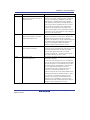
iv. Document Conventions
iv. Document Conventions
This manual uses the following typographic conventions:
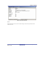
CONVENTION
MEANING
[Menu->Menu Option]
Bold text with ‘->’ is used to indicate menu options (for example,
[File->Save As...]).
‘dialog name’
The ‘’ is used to indicate the name of a dialog box or menu.
‘Filename.ext’
Bold Courier Font is used to indicate filenames.
“enter this string”
Used to indicate text that must be entered (excluding the “” quotes).
Key+Key
Used to indicate required key presses. For example. Ctrl+N means
press the Ctrl key and then, whilst holding the Ctrl key down, press
the N key.
Â
When this symbol is used, it is always located in the left-hand
margin. It indicates that the text to its immediate right is describing
“how to” do something.
(The “how to” symbol)
Table 1: Typographic Conventions
Windows® is a registered trademark of Microsoft Corporation.
R20UT0508EJ1100 Rev.11.00
Mar 07, 2012
Page xxi of xxii
iv. Document Conventions
R20UT0508EJ1100 Rev.11.00
Mar 07, 2012
Page xxii of xxii
Chapter 1 Introduction
Chapter 1 Introduction
The Renesas Flash Development Toolkit (FDT) is an on-board FLASH programming tool for
Renesas Flash microcomputers that provides a high-performance and user-friendly Graphical User
Interface (GUI).
Embedded software development projects created using the Renesas High-performance Embedded
Workshop (HEW) may be programmed into Renesas Flash devices using FDT.
FDT may also be used as a general purpose S-Record or Hex editor.
1.1
Key Features
⎯ Standard window operation based on the 32-bit Windows® GUI.
⎯ Various online help functions.
⎯ Selectable messaging levels.
⎯ Simple programming environment; optionally controls an adapter board.
⎯ Serial communication.
⎯ USB communications supported via USB Interface Boards
⎯ USB communications directly to selected target devices.
⎯ Wait for Script File facility
⎯ Multiple flash areas in a single image (DDI)
⎯ Unique code programming for serial numbering etc.
⎯ Programming and erasing of ID codes (key codes) for generic boot devices with intelligent
flash security (IFS)
1.2
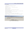
New Features
FDT4.08 has the following new features:
⎯ Support for the FINE-communications interface with the E1 or E20 (for devices that
support FINE communications)
⎯ A selectable option for whether to allow erasure of User Boot Area
R20UT0508EJ1100 Rev.11.00
Mar 07, 2012
Page 1 of 216
Chapter 1 Introduction
R20UT0508EJ1100 Rev.11.00
Mar 07, 2012
Page 2 of 216
Chapter 2 System Overview
Chapter 2 System Overview
FDT provides a method of programming, erasing and reading from Renesas Flash devices.
Workspaces and Projects can be used in order to save the settings between sessions, for easy
switching between different settings, and to allow experienced users to configure the settings for
less experienced operators. FDT is designed to provide a common look and feel, independent of
the actual device to be programmed.
FDT employs a hierarchical structure so that work can be organised in a logical manner. The top
level of the structure is the workspace.
To be useful, the workspace must contain at least one project. In order to create a project, a
workspace must be created first.
Each project specifies its own target device configuration (specified when creating the project) and
set of target files (S-Record / Hex / Binary) that can be used to program the device.
The project settings for the target device connection need only be set once, as they can be stored
between sessions by saving the Project.
A single project within the workspace is active at any point in time. The active project is the
context to which all ‘Device’ Menu, ‘Project’ Menu and ‘Project’ Toolbar commands will be
directed.
When a project has been created, target files can be added to it. These files may:
⎯ Be used to program the device.
⎯ Be used to build a Device Image.
⎯ Be opened in the hex editor.
⎯ Be marked as being destined for the User Boot Area (for devices which support this).
⎯ Have their checksum calculated
⎯ Have their data block usage displayed
⎯ Be compared against the data already programmed to the device
When using a project it is possible to take advantage of the following FDT features:
⎯ Advanced messaging levels.
⎯ Device Image builder.
⎯ Uploading data from the target device.
⎯ Viewing uploaded data in big or little endian, or floating point representation.
R20UT0508EJ1100 Rev.11.00
Mar 07, 2012
Page 3 of 216
Chapter 2 System Overview
⎯ Simple Interface Mode – for simplifying the user interface once the project is configured.
⎯ Automatic masking of non-Flash areas in files upon opening project open
⎯ Automatic masking of reserved sections within Flash areas
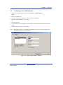
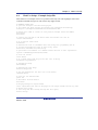
2.1
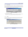
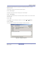
User Interface
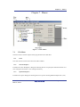
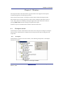
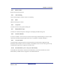
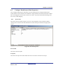
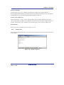
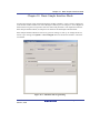
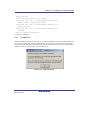
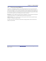
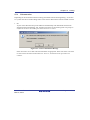
The FDT Graphical User Interface is a Windows® application that presents a work environment,
which allows the user to program FLASH memory.
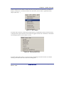
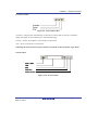
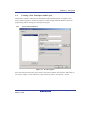
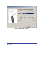
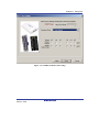
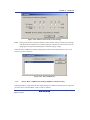
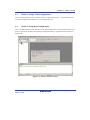
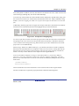
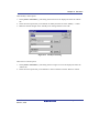
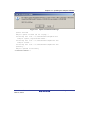
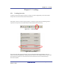
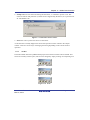
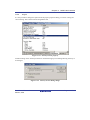
Figure 2-1 FDT Graphical User Interface
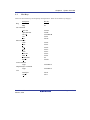
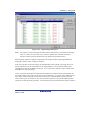
2.1.1
Menu bar
Commands are grouped into related areas on the Menu bar as indicated by the menu titles. Using
the mouse the user can select a command operation, invoke a dialog box or a window to interact
with the system. Clicking the left mouse button on a menu title will pull down that menu, from
R20UT0508EJ1100 Rev.11.00
Mar 07, 2012
Page 4 of 216
Chapter 2 System Overview
which a selection can be made. If a menu item does not perform an action directly, but instead
displays a dialog box or window for further user interaction, then its name is appended with an
ellipsis (three dots, ...).
Figure 2-2 Menu Ellipsis
If a menu item can also be invoked by pressing a hot key (a combination of keys), then the hot key
is displayed to the right of the item. If a menu item toggles a feature ON or OFF then a check mark
will be displayed next to its text when it is ON:
Figure 2-3 Checked Menu Items
If a menu item has the symbol ( ) next to it then a cascading or hierarchical menu is available.
Clicking on the menu item will reveal the cascading menu:
R20UT0508EJ1100 Rev.11.00
Mar 07, 2012
Page 5 of 216
Chapter 2 System Overview
Figure 2-4 Cascading Menus
Menus can also be selected directly from the keyboard by pressing the ALT key followed by the
corresponding key of the underlined letter or number for the menu item that the user wants to
select, e.g. press ALT+F, S in sequence to Save the active file ([File->Save]).
2.1.2
Toolbars
FDT has several toolbars located below the Menu bar. This provides quick access to FDT features
by clicking the respective button with the mouse.
Figure 2-5 FDT Toolbars
The buttons on each toolbar are arranged in associated groups. To find out the function of the
button, move the mouse over the button and a hint will be displayed next to the button and in the
status bar. The toolbar buttons can be customised to provide a button for the majority of the
features available in FDT and can be arranged in an order that the user finds convenient. For more
details about changing the arrangement of the toolbar buttons and a detailed description of each
button's function, see Chapter 6.
R20UT0508EJ1100 Rev.11.00
Mar 07, 2012
Page 6 of 216
Chapter 2 System Overview
Edit toolbar
Figure 2-6 Edit Toolbar
Save File - saves the active file.
Cut - cuts data to the clipboard.
Copy - copies data to the clipboard.
Paste - pastes data from the clipboard.
Open a Data File - Opens an S-Record or other data file.
FDT toolbar
Figure 2-7 FDT Toolbar
R20UT0508EJ1100 Rev.11.00
Mar 07, 2012
Page 7 of 216
Chapter 2 System Overview
Connect - connects the device to the interface.
Disconnect - disconnects the device from the interface.
Erase Blocks - launches the 'Erase Block' dialog box to erase all or individual blocks of the device
FLASH memory.
Blank Check - checks whether or not the FLASH section of the target device is blank.
Upload - launches the 'Upload Image' dialog box to allow data to be obtained from the target
device.
Download Active File - downloads the file which is active in the hex editor.
Checksum - returns a checksum of the data in the FLASH.
Go from Address - launches a dialog to select the address to execute from.
Run - places the device into user mode and if necessary supplies power so that programmed device
code can be tested
Block Locking - configure the block locking options (if the device supports block locking)
Set ID Code - sets an ID code (if the device supports this)
Cancel - cancels the current FLASH operation.
Configure Flash Project - launches the 'Project Properties' dialog box (or the Project Wizard if the
project is not yet configured).
R20UT0508EJ1100 Rev.11.00
Mar 07, 2012
Page 8 of 216
Chapter 2 System Overview
S Record / Data File toolbar
Figure 2-8 S Record / Data File Toolbar
View as Bytes - view the file data as 8 bit bytes.
View as Words - view the file data as 16 bit words.
View as DWords - view the file data as 32 bit double words.
Endian - toggles between little and big endian viewing.
Align view to 8 bytes - data is displayed on each line as 8 bytes. The number of bytes that can be
accommodated on each line is dependent upon the size of the window.
Toggle ASCII - turns ASCII data ON or OFF
Find - launches the 'Find' dialog box.
Find and Replace - launches the Replace dialog box.
Create Selection - selects a block of the specified size in the active file.
Fill selection - launches the 'Fill' dialog box.
Properties - launches a dialog with information about the active file.
R20UT0508EJ1100 Rev.11.00
Mar 07, 2012
Page 9 of 216
Chapter 2 System Overview
Protection toolbar
Figure 2-9 Protection Toolbar
Automatic - Set protection automatically on disconnect (if more than one option is available a
dialog will appear to select which type to automatically apply)
Prompt - Ask the user whether to set protection on disconnect.
None - Never set protection on disconnect.
NB setting the protection may stop any further connections to that particular target device
Search toolbar
Figure 2-10 Search Toolbar
R20UT0508EJ1100 Rev.11.00
Mar 07, 2012
Page 10 of 216
Chapter 2 System Overview
Find in Files - finds selected data in selected files.
Data - is used for the searches.
Find - locates data in active file.
Find Next - locates next occurrence of search criteria.
Find Previous - locates previous occurrence of search criteria.
2.1.3
Status Bar
The Status Bar is located at the bottom of the FDT application window. It provides the user with
information about what the application is doing. The left section of the Status Bar describes the
action of the Toolbar items as the mouse arrow is positioned over a button, as well as displaying
operation status information. When an action is being performed, a progress bar is displayed to
show the progress of the current operation. The last section of the bar indicates the state of the
toggling keyboard keys such as the Caps Lock, Insert and Number Lock keys.
R20UT0508EJ1100 Rev.11.00
Mar 07, 2012
Page 11 of 216
Chapter 2 System Overview
2.1.4
Pop-up menus
Many windows have local pop-up menus in order to make commonly used features easier to
access. These menus are invoked by clicking the right mouse button in the window (or pressing
SHIFT+F10) and then selecting the required menu option. An example pop-up menu is:
Figure 2-11
Pop-up Menu
The contents and operation of specific pop-up menus are explained in detail in the description of
each FDT window, see the Chapter 8, Windows.
2.2
Help
FDT has a standard Windows® help system. This provides on-line information for using the
system.
Help can be invoked by pressing the F1 key or via the Help menu.
R20UT0508EJ1100 Rev.11.00
Mar 07, 2012
Page 12 of 216
Chapter 2 System Overview
2.3
Hot Keys
There are various hot keys for frequently used operations. These are as follows by category:Description
Hot Key
Help
F1
Help
File Commands
Close File
Ctrl+F4
Open Data File
Ctrl+R
Save All
Ctrl+Shift+H
Save
Ctrl+S
Exit
Alt+F4
Edit Commands
Undo
Ctrl+Z
Redo
Ctrl+Y
Cut
Ctrl+X
Copy
Ctrl+C
Paste
Ctrl+V
Select All
Ctrl+A
Find
Ctrl+F
Find In Files
F4
Replace
Ctrl+H
Tools Commands
Login
Ctrl+Shift+U
Simple Interface Commands
Login
Ctrl+Shift+U
Workspace
Alt+K
Output
Alt+U
View
R20UT0508EJ1100 Rev.11.00
Mar 07, 2012
Page 13 of 216
Chapter 2 System Overview
Description
Hot Key
View as ASCII
Alt+A
Window
View as Bytes
Alt+1
View as Word
Alt+2
View as Dword
Alt+4
Align to 8 Bytes
Alt+8
Connect
Ctrl+Alt+C
Erase Flash Blocks
Ctrl+Alt+E
Device
Blank Check
Ctrl+Alt+B
Upload Image
Ctrl+Alt+U
Download Active File
Ctrl+Alt+P
Flash Checksum
Ctrl+Alt+S
Go From Address
Ctrl+Alt+G
Run
Ctrl+Alt+R
Block Locking...
Ctrl+Alt+L
Set ID Code…
Ctrl+Alt+T
Cancel Operation
Ctrl+Break
Configure Flash Project
Alt+Shift+R
Data File
Suppress request to save changes to Hold Shift key when closing data file
a data file when closing it (do not
save changes)
R20UT0508EJ1100 Rev.11.00
Mar 07, 2012
Page 14 of 216
Chapter 3 Using FDT
Chapter 3 Using FDT
3.1
Quickstart
The stages required in order to program a device are as follows:
1) Start FDT by selecting ‘Start’ -> ‘Programs’ -> ‘Renesas’ -> ‘Flash Development Toolkit
4.08’, then the ‘Flash Development Toolkit 4.08’ shortcut [see section 3.3]
2) Create a Workspace and Project [see section 3.4.1]
3) Configure the Project using the Flash Project Wizard (select device, kernel, port, mode etc)
[see sections 3.4.2 to 3.4.8 or section 3.5 for Generic Boot]
4) Add the file or files that you want to download to the project [see sections 8.1.2.1/8.2.2/3.7].
You can now download individual files by right clicking on them in the Workspace Window,
or merge multiple files into a device image (using the Project-> Rebuild Image menu item)
and download that (using the Project-> Download Image menu item).
Alternatively, to start in FDT Basic Simple Interface Mode:
1) Select ‘Start’->‘Programs’ -> ‘Renesas’ -> ‘Flash Development Toolkit 4.08’, then the ‘Flash
Development Toolkit 4.08 Basic’ shortcut [see section 3.3]
2) Configure the settings using the Wizard (select device, kernel, port, mode etc) [see sections
3.4.2 to 3.4.8 or section 3.5 for Generic Boot]
3) Select the flash area that you want to program (User Area or User Boot Area).
4) Select the file to program for each enabled area
5) Select the Program Flash Button.
6) Disconnect when programming is completed
R20UT0508EJ1100 Rev.11.00
Mar 07, 2012
Page 15 of 216
Chapter 3 Using FDT
3.2
3.2.1
Background Information
What are the User Area, User Boot Area and Data Areas?
The normal area of (internal) flash for Renesas devices, for user programs is known as the User
Area. This is where the code is stored which gets executed when the device is reset into User
Mode. The User area can normally be programmed from a Boot Mode or User Mode connection.
On some devices there is an additional area of flash known as the User Boot Area. This is where
the code is stored which gets executed when the device is reset into User Boot Mode. The User
Boot Area tends to be much smaller than the User Area and is typically used for storing an
alternative boot stub, for setting up communication via some other communications medium /
protocol. Normally, the User Area and the User Boot Area both start at the same address – this is
possible because only one is ever mapped into the memory map at one time. It is only possible to
program the User Boot Area from Boot Mode - not from User Mode.
On some devices there is an additional area of flash known as the Data Area. This area normally
resides at the other end of the memory map to the User Area, and unlike the case of the User
Boot Area, the Data Area is not contiguous with the User Area and always exists in the memory
map.
3.2.2
What is the difference between Boot Mode and User Mode?
The Renesas Flash devices have different modes of operation which are controlled by the state of
the mode pins when the device is brought out of reset. Most devices have an asynchronous serial
Boot Mode and a User/User Program Mode.
Generally, (asynchronous serial) Boot Mode connections, start with an autobaud – sending
synchronisation data packets to setup initial communications at a given baud rate. Additionally,
for most devices, the entire flash will be erased as part of the connection process, thus preventing
any Intellectual Property held on the device from being read from Boot Mode.
For a User Mode connection, the device must already be programmed with some code which talks
to FDT and allows programming. Most kernels are supplied with a User Mode micro kernel and
test program (*usually called “uGenU.mot” and “xxxxtest.mot”). These files provide a
demonstration of User Mode programming and must be programmed into the device and be
executing before FDT tries to connect in User Mode. User Mode does not normally force an erase
of the flash during the connection process and does not autobaud to setup initial communications.
The demonstration User Mode test programs have the required Bit Rate Register value compiled
into them for setting up initial communications at 9600 baud; hence User Mode kernels need to be
rebuilt for different clock frequencies.
R20UT0508EJ1100 Rev.11.00
Mar 07, 2012
Page 16 of 216
Chapter 3 Using FDT
Note: * Note that where the files are to be used as part of an embedded monitor, the User Mode
kernel files may be also output as binary files (.cde) without the reset vector populated.
Some kernels use only a single file for the User Mode test program (e.g. Protocol C
kernels).
3.2.3
What is the difference between User Mode and User Program Mode?
Some devices use an additional mode pin to protect the flash from being written or erased by
mistake; this pin is normally known as the “Flash Write Enable” pin (FWE) if it has to be logic
high to allow programming, or the “Flash Write Protect” pin (FWP) if it has to be logic low to
allow programming. For these devices, this pin distinguishes “User Mode” from “User Program
Mode”. An FDT User Mode connection expects the device to be in User Program Mode at the
point of programming and erasing, and if using the E8Direct, E8aDirect, E1Direct, or E20Direct,
can reset the device into User Mode to execute the programmed code on disconnection.
3.2.4
What are “Protocol B”, “Protocol C”, “Protocol D” and “Protocol E” Kernels?
“Protocol B” – For 0.35μm devices.
Boot Mode - The kernel (made up of the Boot Mode Micro Kernel, Boot Mode Main Kernel, and
the Write and Erase modules) is held on the PC and downloaded as required. The Boot Mode
kernel does not need to be rebuilt for different crystal frequencies; this information is stored in the
FDT project and downloaded at runtime and initial communication is achieved by the autobaud
(where FDT sends 0x00 data until the device synchronises with it).
User Mode – The User Mode Test Program and User Mode Micro-Kernel need to be already
programmed and executing on the device. The initial Bit Rate Register value is held in the
‘gentest.h’ file and is compiled into the User Mode Test Program; this allows the kernel initialise
the serial communications interface to 9600 baud. If the clock frequency changes from the default
supplied value, the initial Bit Rate Register setting in ‘gentest.h’ [normally MA_BRR_SCI or
MA_BRR_SCI1] will need to be modified and the kernel recompiled. The User Mode Main
Kernel and the Write and Erase modules are held on the PC and downloaded as required.
“Protocol C” – For devices with embedded kernels (Currently 0.18μm).
Boot Mode – A configuration file is stored on the PC which provides FDT with details about the
device, but the kernel (including the Write and Erase modules) resides internally on the device.
There is no need to rebuild anything for different clock frequencies in Boot Mode; this
information is stored in the FDT project and downloaded at runtime and initial communication is
achieved by the autobaud (where FDT sends 0x00 data until the device synchronises with it).
R20UT0508EJ1100 Rev.11.00
Mar 07, 2012
Page 17 of 216
Chapter 3 Using FDT
User Mode – Some boards are supplied with a User Mode kernel. Similarly to the Protocol B User
Mode kernels, User Mode Kernel needs to be already programmed and executing on the device.
The initial Bit Rate Register value is held in the ‘gentest.h’ file and is compiled into the User
Mode Test Program; this allows the kernel initialise the serial communications interface to 9600
baud. If the clock frequency changes from the default supplied value, the initial Bit Rate Register
setting in ‘gentest.h’ [normally MA_BRR_SCI or MA_BRR_SCI1] will need to be modified and
the kernel recompiled. The main difference to the Protocol B User Mode Kernels is that the Write
and Erase modules are held internally on the device.
“Protocol D” – For R8C and former Mitsubishi family devices (eg. M16C, M32 etc).
The E8 and E8a boards can be used with some Protocol D devices. The kernels are internal to the
device, but FDT uses configuration files to store information about the device characteristics.
“Protocol E” – For some H8/Tiny and H8/SLP (Super Low Power) devices (please refer to
'readme' text file for details).
Although FDT can communicate to H8/Tiny and H8/SLP devices with COM or E8aDirect (as
“Protocol B”), FDT can also communicate to H8/Tiny and H8/SLP devices with E8a as “Protocol
E”. It is important to note though that key FDT functions are not available in “Protocol E”:
• Erasing Data from the FLASH ROM is unavailable (although all FLASH ROM data is still
erased during connection)
• Uploading the FLASH ROM Data is unavailable
• Performing a Blank Check is unavailable
• Readback Verify is unavailable (but FDT will automatically perform a checksum after
programming)
3.2.5
What is the fcf file, and can I edit it?
Stored alongside the other kernel files, the .fcf (Flash Configuration File) file holds details about
the device and kernel. The contents indicate the RAM size, flash-memory size, block
configuration, default baud rate, and default crystal frequency. This file is protected by a
checksum, so editing it will render this invalid, which the FDT will detect. Upon detecting an
invalid checksum for the file, the FDT will warn the user, but will not prevent use of the modified
files.
R20UT0508EJ1100 Rev.11.00
Mar 07, 2012
Page 18 of 216
Chapter 3 Using FDT
3.2.6
Can I use FDT if I do not have Local Machine Administrator rights for my PC?
Yes, but only once it is installed and configured. To install FDT and for various configuration
tasks, you must have local administrator rights; this is because some settings are stored in the
HKEY_LOCAL_MACHINE registry area. Once FDT is installed and configured you will be able
to use it with certain limitations. Configuration tasks such as adding new kernel entries to the
registry so that they will be available in the Project Wizard in future requires Local Machine
Administrator rights. This includes adding the Prior Generic Device entry (an administrator must
first connect to the Generic Device to allow the Prior Generic Device entry to be created.
3.2.7
How do I recompile a kernel?
It is recommended that the original kernel is copied to another directory and that this copy is
edited, thus leaving the original kernel unmodified. When using the kernel for the first time, you
will need to browse to the alternate location to find the fcf file.
If the kernel has been written using Hew, there will be a Hew workspace file in the project
subdirectory of the kernel. This should be opened from Hew.
If the kernel has been written based upon compilation from the command line, you will need to
run the buildall.bat file from a Dos shell session after setting up the environment variables for the
compiler so that it can be run from the command line. Please refer to the compiler manual for full
details of how to do this. An example environment batch file used to set the environment settings
for the Renesas H8 compiler version 4.0a is shown below:
Setenv.bat:
SET CH38=C:\hew\tools\Renesas\h8\4_0_A\INCLUDE
PATH=%PATH%;C:\hew\tools\Renesas\h8\4_0_A\bin
set DOS16M= @1M-31M
SET CH38TMP=c:\TEMP
Note:
The above batch file should be modified to reflect the path of your compiler.
Ensure that the specified temporary directory exists and is writeable.
R20UT0508EJ1100 Rev.11.00
Mar 07, 2012
Page 19 of 216
Chapter 3 Using FDT
3.2.8
How do I use the supplied demonstration User Mode Kernels?
To use the demonstration User Mode kernels, you must first add the User Mode Micro Kernel and
User Mode Test Program from the kernel directory (“uGenU.mot” and “xxxxtest.mot”) to
a Boot Mode Project and build the User Area Device Image. Next, connect in Boot Mode and
program the image to the device, disconnect and reset the device into User Mode. Create another
project in the workspace, but this time set it as a User Mode Connection Type, and connect in User
Mode. FDT will start communications with the User Mode Test Program at 9600bps and then
change to the baud rate set in the project. Note that the device does not automatically erase during
connections in User Mode. It is not possible to reprogram the FLASH whilst the reprogramming
code is executing from the FLASH so all of the kernel modules needed to keep the connection to
FDT are copied into the RAM to leave the FLASH ROM available for reprogramming. Because of
this, it is possible to erase the entire flash and reprogram it in user mode, but note that if the device
is reset after erasure and before it is reprogrammed, it will not be possible to reconnect in User
Mode until the device has had the User Mode Micro Kernel and User Mode Test Program
reprogrammed into it Boot Mode.
3.2.9
Can I modify the User Mode kernels to work for a different clock frequency?
It is recommended that the original kernel is copied to another directory and that this copy is
edited, thus leaving the original kernel unmodified. When using the kernel for the first time, you
will need to browse to the alternate location to find the fcf file.
The User Mode kernels need to be rebuilt if a different clock frequency is going to be used. The
initial Bit Rate Register value is held in the ‘gentest.h’ file and is compiled into the User Mode
Test Program; this allows the kernel initialise the serial communications interface to 9600 baud. If
the clock frequency changes from the default supplied value, the initial Bit Rate Register setting in
‘gentest.h’ [normally MA_BRR_SCI or MA_BRR_SCI1] will need to be modified and the kernel
recompiled. Refer to the device hardware manual for details of how to calculate the Bit Rate
Register value.
R20UT0508EJ1100 Rev.11.00
Mar 07, 2012
Page 20 of 216
Chapter 3 Using FDT
3.3
3.3.1
Starting FDT
Starting FDT without Security or Simple Interface Mode enabled
To start FDT, open the 'Start' menu of Windows® and select 'Programs' -> 'Renesas' -> 'Flash
Development Toolkit 4.08', then the 'Flash Development Toolkit 4.08' shortcut. The 'Welcome'
dialog box will open by default.
Figure 3-1 Welcome Dialog
To create a new workspace, select 'Create a new Project Workspace' and click the 'OK' button (see
section 3.4.1 for details). To open a recent workspace, select 'Open a recent project workspace' and
the workspace to be opened from the list box. To open an existing workspace which is not in the
list of recently used workspaces, select 'Browse to another project Workspace'. Finally, click the
'OK' button.
3.3.2
Starting FDT in Basic Simple Interface Mode
To start FDT in Basic Simple Interface Mode, open the 'Start' menu of Windows® and select
'Programs' -> 'Renesas' -> 'FLASH Development Toolkit 4.08', then the 'Flash Development
Toolkit 4.08 Basic' shortcut. The previous FDT Basic settings will be restored, and new settings
can be entered by selecting the Options->New Settings& menu item.
3.3.3
Starting FDT by double clicking on a workspace file
FDT can be started by double clicking on a workspace file from Windows® Explorer. This will
cause FDT to load the selected workspace upon start up.
R20UT0508EJ1100 Rev.11.00
Mar 07, 2012
Page 21 of 216
Chapter 3 Using FDT
3.3.4
Starting FDT by double clicking on a data file
FDT can be started by double clicking on a registered data file from Windows® Explorer (if this
default option was not unselected during installation). This will cause FDT to load the selected
data file upon start up.
3.3.5
Starting FDT by double clicking on a w4f script configuration file
FDT can be started by double clicking on a .w4f script configuration file from Windows®
Explorer. This will cause FDT to start in Wait For Script mode and load the selected
configuration.
3.3.6
Starting FDT with Simple Interface Mode enabled
If FDT was exited from Simple Interface Mode (see section Chapter 9 ) FDT will return straight
back to that mode.
3.3.7
Starting FDT with Access Rights password security enabled
If the Access Rights password security has been enabled, FDT will display the login dialog before
allowing the workspace to be opened. See Chapter 5 for further details.
3.3.8
Starting FDT by double clicking on a .fpf4 packaged project file
FDT can be started by double clicking on a .fpf4 packaged project file from Windows® Explorer.
This will cause FDT to unpackage the project and start in Simple Interface Mode.
3.3.9
Starting FDT from the command line
3.3.9.1. Opening data files from the command line
"<FDT path>\FDT.exe" /DISCRETESTARTUP "osre \"< Filename >\""
eg:
"C:\Program Files\Renesas\FDT4.08\FDT.exe" /DISCRETESTARTUP "osre \"C:\Program
Files\Renesas\files\myfile.mot\""
This is the method used when an FDT data file is double clicked in Windows® Explorer
R20UT0508EJ1100 Rev.11.00
Mar 07, 2012
Page 22 of 216
Chapter 3 Using FDT
3.3.9.2. Opening workspace files from the command line
"<FDT path>\FDT.exe" /DISCRETESTARTUP "ow \"<Long Path Workspacename>\""
eg
"C:\Program Files\Renesas\FDT4.08\FDT.exe" /DISCRETESTARTUP "ow \"C:\Program
Files\Renesas\FDT4.08\Workspaces\1234\1234.AWS\""
This is the method used when an FDT workspace is double clicked in Windows® Explorer
3.3.9.3.
Opening data files from the command line with Access Rights password security
enabled
"<FDT path>\FDT.exe" "arl \"<Username>\" \"<Password>\"" /DISCRETESTARTUP "osre \"<
Filename >\""
eg
"C:\Program Files\Renesas\FDT4.08\FDT.exe" "arl \"Administrator\" \"password\""
/DISCRETESTARTUP "osre \"C:\Program Files\Renesas\files\myfile.mot\""
3.3.9.4. Opening w4f Script Configuration files from the command line
"<FDT path>\FDT.exe" /DISCRETESTARTUP "w4fRun \"<filename>\""
eg
"C:\Program Files\Renesas\FDT4.08\FDT.exe" /DISCRETESTARTUP "w4fRun \"C:\Program
Files\Renesas\FDT4.08\myconfig.w4f\""
This is the method used when an FDT Script Configuration file is double clicked in Windows®
Explorer
3.3.9.5. Opening w4f Script Configuration files from the command line with Access Rights
password security enabled
"<FDT path>\FDT.exe" "arl \"<Username>\" \"<Password>\"" /DISCRETESTARTUP "w4fRun
\"<filename>\""
eg
"C:\Program Files\Renesas\FDT4.08\FDT.exe" "arl \"Administrator\" \"password\""
/DISCRETESTARTUP "w4fRun \"C:\Program Files\Renesas\FDT4.08\myconfig.w4f\""
R20UT0508EJ1100 Rev.11.00
Mar 07, 2012
Page 23 of 216
Chapter 3 Using FDT
3.3.9.6. Starting FDT Basic Simple Interface Mode from the command line
"<FDT path>\FDT.exe" /DISCRETESTARTUP "SimpleInterfaceMode /u \"<User Area
Filename>\" /b \"<User Boot Area or Data Area Filename>\""
eg
"C:\Program Files\Renesas\FDT4.08\FDT.exe" /DISCRETESTARTUP "SimpleInterfaceMode /u
\"c:\upload1.mot\" /b \"c:\upload0.mot\""
Note that the /u <User Area Filename> and the /b <User Boot Area> are optional. Additionally,
adding /r causes the last settings to be restored and the configuration Wizard will not be displayed.
R20UT0508EJ1100 Rev.11.00
Mar 07, 2012
Page 24 of 216
Chapter 3 Using FDT
3.4
Creating a New Workspace and Project
When FDT is started in full mode (not FDT Basic Simple Interface Mode), a workspace and
project must be opened or created. See Chapter 10 Basic Simple Interface Mode for details on
programming without setting up a workspace and project.
3.4.1
New Project Workspace
Figure 3-2 New Workspace
Enter the workspace name (the project name is the same by default), then click the 'OK' button. If
you wish to change or create a directory, input a directory name or use 'Browse...' button.
R20UT0508EJ1100 Rev.11.00
Mar 07, 2012
Page 25 of 216
Chapter 3 Using FDT
3.4.2
Choose Device and Kernel (not Generic Boot*)
Select the device/kernel you wish to use from the list. The list can be filtered by typing into the
Filter box, note that if the project name starts with three or more numbers then these will
automatically be entered into the Filter box. It is possible to have more than one kernel option
displayed for a given device, and double clicking on a kernel will open an optional "readme.txt"
file that has information about the kernel (such as the device, version number and the compilers it
was created with). If you have an alternative kernel elsewhere, which is not in the list, select
'Other...' to specify the kernel Flash Configuration File (.fcf).
®
Note: Registering a new kernel requires 'Administrator' privileges. On Windows Vista or
®
Windows 7 this may require the user to provide extra confirmation or credentials.
* For connection to a Generic Boot Device see the "Configuring a Project for a Generic Boot
Device" section.
Figure 3-3 Device and Kernel Selection
R20UT0508EJ1100 Rev.11.00
Mar 07, 2012
Page 26 of 216
Chapter 3 Using FDT
Supplementary:
1. Type Names of Devices Intended for x-Line Connection Only
The suffix “_xLine” for type names indicates that the devices are intended for x-line
connection only.
2. Type Names of Devices That Vary According to Whether or Not ECC Data is Included
If you wish to program a device that has E2 data flash memory, select either of the following
type names according to whether or not the data to be written to the device includes ECC data.
(a) R32C/100 series
-
When ECC data is included: R5F64xxx_ECC
-
When ECC data is not included: R5F64xxx
(b) M16C/50 series
-
When ECC data is included: R5F35Mxx_ECC_xLine
-
When ECC data is not included: R5F35Mxx_xLine
R20UT0508EJ1100 Rev.11.00
Mar 07, 2012
Page 27 of 216
Chapter 3 Using FDT
3.4.3
Communications Port
Select the port (and interface if available) from the drop-down list, then click the 'Next' button.
Figure 3-4 Communications Port
R20UT0508EJ1100 Rev.11.00
Mar 07, 2012
Page 28 of 216
Chapter 3 Using FDT
E8a
Debug Interface with E8a
E8
Debug Interface with E8
E1
Debug Interface with E1
E20
Debug Interface with E20
E8aDirect
UART with E8a
E8Direct
UART with E8
E1Direct
UART with E1 (include the FINE interface)
E20Direct
UART with E20 (include the FINE interface)
COM
RS-232C
USB Direct
USB
Supplementary:
Setting to Place the Low Level on the Reset Pin at the Time of Disconnection
If ‘Set Reset pin as low when disconnecting’ is selected in the ‘Communications Port’ dialog box,
a low-level signal will be output by the reset pin when the device is disconnected. This option is
only available when E8a, E8aDirect, E1, E1Direct, E20, or E20Direct has been selected for ‘Select
port’.
R20UT0508EJ1100 Rev.11.00
Mar 07, 2012
Page 29 of 216
Chapter 3 Using FDT
3.4.4
Device Settings
Enter values for the device settings; enter the input clock, then select the main and peripheral
clock multipliers from the drop-down lists, and click the 'Next' button.
Figure 3-5 Device Settings
R20UT0508EJ1100 Rev.11.00
Mar 07, 2012
Page 30 of 216
Chapter 3 Using FDT
Supplementary:
1. Clock Setting
Select the clock source to be supplied to the CPU.
(a) When the device in use does not support switching of clock sources:
Clock oscillator or clock resonator: [External Clock or Resonator]
(b)
When the device in use supports switching of clock sources:
Clock oscillator: [External Clock]
Clock resonator: [External Resonator]
On-chip oscillator: [Internal Clock]
2. CPU Crystal Frequency
Enter the frequency of the CPU clock or the crystal generator. This can be specified up to 4
decimal places. The target device, the kernel and the Clock Mode determine the valid range.
3. Clock Mode
If enabled, select the required value from the drop-down list.
4. Multiplier for CKM
If enabled, select the input clock multiplier for the master (system) clock. The available
options depend upon the target device, the kernel and the Clock Mode.
5. Multiplier for CKP
If enabled, select the input clock multiplier for the peripheral clock. The available options
depend upon the target device, the kernel and the Clock Mode.
Note: To enter the clock mode, input clock, and multipliers, refer to the device hardware manual
and/or the target board manual to confirm the values required.
R20UT0508EJ1100 Rev.11.00
Mar 07, 2012
Page 31 of 216
Chapter 3 Using FDT
3.4.5
Connection Type
Select whether the connection is for Boot Mode or User Mode in the 'Connection Type' dialog.
Additionally, for a connection to a kernel that is still running on the device from a previous
session, select the 'Kernel already running' check box. Next, select the communication speed (bps)
if the default value is not correct or not present. Speeds where the target error rate is greater than
4%, or the E8Direct\E8aDirect\E1Direct\E20Direct error rate is greater than 0% are automatically
removed from the recommended list. When using the E8Direct\E8aDirect\E1Direct\E20Direct the
'User Specified' connection speed option is enabled; when selected, this allows the user to specify
a non-standard baud rate. The error rate will be displayed this takes into account the target
peripheral clock rate, the target Bit Rate Register calculation formula, and the
E8Direct\E8aDirect\E1Direct\E20Direct characteristics.
Click the 'Next' button to continue.
Figure 3-6 Connection Type
R20UT0508EJ1100 Rev.11.00
Mar 07, 2012
Page 32 of 216
Chapter 3 Using FDT
Note that 'Use Default' is designed for use with the Renesas Evaluation Board or Evaluation
Development Kits. Uncheck this to allow manual selection of the bit rate.
3.4.6
Programming Options
Select the protection level for programming the FLASH ROM and the messaging level, then click
the 'Finish' button, or if the E8Direct\E8aDirect\E1Direct\E20Direct was selected, click 'Next' to
continue.
Figure 3-7 Programming Options
R20UT0508EJ1100 Rev.11.00
Mar 07, 2012
Page 33 of 216
Chapter 3 Using FDT
3.4.7
E8Direct\E8aDirect\E1Direct\E20Direct Pin Settings
[Only if the E8Direct, E8aDirect, E1Direct, or E20Direct is selected] Select the 'Operating Mode'
and 'Clock Mode' and if 'User Defined', set the pin settings. [For 'Boot Mode' projects set the 'Boot
Mode Outputs' and the 'Boot Mode Setting' for the required mode, for 'User Mode' projects set the
'User Mode Outputs', 'User Mode Setting' and the 'User Program Mode Setting' for the required
mode.] Click the 'Next' button to continue. "*Mode Outputs" sets which pins are driven, "*Mode
Setting (High)" sets whether output pins are driven High (checked) or Low (Unchecked).
Notes: Setting the mode pins requires caution. Please confirm the pin settings with the hardware
manual even if a default setting is available. Note that in some devices, changing the mode pin
setting changes the maximum supply voltage.
Figure 3-8 E8Direct Pin Settings
R20UT0508EJ1100 Rev.11.00
Mar 07, 2012
Page 34 of 216
Chapter 3 Using FDT
Figure 3-9 E8aDirect Pin Settings
R20UT0508EJ1100 Rev.11.00
Mar 07, 2012
Page 35 of 216
Chapter 3 Using FDT
Figure 3-10 E1Direct Pin Settings
R20UT0508EJ1100 Rev.11.00
Mar 07, 2012
Page 36 of 216
Chapter 3 Using FDT
Figure 3-11 E20Direct Pin Settings
R20UT0508EJ1100 Rev.11.00
Mar 07, 2012
Page 37 of 216
Chapter 3 Using FDT
3.4.8
Reset Pin Settings
[Only if the E8Direct or E8aDirect is selected] Select the 'Operating Mode' and 'Clock Mode' and
if 'User Defined', set the Reset pin settings. Set the 'RESET Outputs' and the 'RESET Setting
(High)' for the mode required immediately after disconnection. Click the 'Finish' button. "RESET
Outputs" sets which pins are driven, "RESET Setting (High)" sets whether output pins are driven
High (checked) or Low (Unchecked).
Notes: Setting the mode pins requires caution. Please confirm the pin settings with the hardware
manual even if a default setting is available. Note that in some devices, changing the mode pin
setting changes the maximum supply voltage.
Figure 3-12 E8Direct RESET Pin Settings
R20UT0508EJ1100 Rev.11.00
Mar 07, 2012
Page 38 of 216
Chapter 3 Using FDT
Figure 3-13 E8aDirect RESET Pin Settings
R20UT0508EJ1100 Rev.11.00
Mar 07, 2012
Page 39 of 216
Chapter 3 Using FDT
Figure 3-14 E1Direct RESET Pin Settings
R20UT0508EJ1100 Rev.11.00
Mar 07, 2012
Page 40 of 216
Chapter 3 Using FDT
Figure 3-15 E20Direct RESET Pin Settings
R20UT0508EJ1100 Rev.11.00
Mar 07, 2012
Page 41 of 216
Chapter 3 Using FDT
3.5
Configuring a Project for a Generic Boot Device
It is also possible to connect to a Generic Boot Renesas Device - where you do not need a kernel
or configuration file installed, instead FDT extracts the required information from the device itself.
Because of this, the device must be connected and set into Boot Mode at the time you create the
project. If a Generic Boot device is selected, then a series of screens appear displaying the results
of the inquiry functions, you will be required to make selections about the device and clock mode
(one boot program may be shared for multiple devices).
3.5.1
New Project Workspace
Enter the workspace name, then click the 'OK' button. (Specify whether or not a directory is to be
created and a location.)
Figure 3-16 New Workspace
R20UT0508EJ1100 Rev.11.00
Mar 07, 2012
Page 42 of 216
Chapter 3 Using FDT
3.5.2
Generic Boot - Choose Device and Kernel
(1) When using a device that does not support FINE communications
Select 'Generic Boot Device' (or a device supported by Generic Boot) and click 'Next'.
Figure 3-17 Generic Boot Device Selection
Note: Some Protocol C devices which appear in the device list are supported by using Generic
Boot. This means that when one of these devices is selected in the Project Wizard, FDT
will behave as if "Generic BOOT Device" was selected, and will connect to the device to
obtain the device characteristics instead of using an existing fcf file for this information.
R20UT0508EJ1100 Rev.11.00
Mar 07, 2012
Page 43 of 216
Chapter 3 Using FDT
Figure 3-18 Device Support via Generic Boot
R20UT0508EJ1100 Rev.11.00
Mar 07, 2012
Page 44 of 216
Chapter 3 Using FDT
(2) When using a device that supports FINE communications
Select 'xxxxxFINEx(Generic)' and click 'Next'.
Figure 3-19 Generic Boot Device Selection (FINE)
R20UT0508EJ1100 Rev.11.00
Mar 07, 2012
Page 45 of 216
Chapter 3 Using FDT
3.5.3
Generic Boot - Communications Port
Select the port (and interface if available) from the drop-down list, then click the 'Next' button.
Figure 3-20 Communications Port
R20UT0508EJ1100 Rev.11.00
Mar 07, 2012
Page 46 of 216
Chapter 3 Using FDT
3.5.4
Generic Boot - E8Direct Pin Settings [E8Direct connection only]
If E8Direct is selected the following two screens will be shown. The first allows optional power to
be supplied to the target board via the E8 (see also section 3.6.1)
Figure 3-21 E8 Target Power Supply Selection
WARNING: Damage to the target device may occur if the incorrect voltage setting is chosen!
This will be followed by the mode pin settings dialog, required to place the device into Boot
Mode. Click 'OK' to continue.
R20UT0508EJ1100 Rev.11.00
Mar 07, 2012
Page 47 of 216
Chapter 3 Using FDT
Figure 3-22 E8Direct Generic Device Pin Settings
Note: Setting the mode pins using the E8Direct requires caution. Please confirm the pin settings
with the hardware manual even if a default setting is available. Note that in some devices,
changing the mode pin setting changes the maximum supply voltage.
If the E8 has not yet been restarted as an E8Direct device then the following messages will appear
in the FDT output window:
Preparing for re-enumeration of E8 to E8Direct...
Sending re-enumeration command...
Request sent successfully, closing E8 Comms...
At the same time Windows® will re-enumerate the device (see also Chapter 13 - E8Direct).
When the 'Select USB Device' Dialog is displayed you must select which E8Direct unit is to be
used to set up the connection.
R20UT0508EJ1100 Rev.11.00
Mar 07, 2012
Page 48 of 216
Chapter 3 Using FDT
Figure 3-23 Select USB Device
3.5.5
Generic Boot - E8aDirect Pin Settings [E8aDirect connection only]
If E8aDirect is selected the following two screens will be shown. The first allows optional power
to be supplied to the target board via the E8 (see also section 3.6.1)
Figure 3-24 Select Target Power
WARNING: Damage to the target device may occur if the incorrect voltage setting is chosen!
This will be followed by the mode pin settings dialog, required to place the device into Boot
Mode. Click 'OK' to continue.
R20UT0508EJ1100 Rev.11.00
Mar 07, 2012
Page 49 of 216
Chapter 3 Using FDT
Figure 3-25 E8aDirect Generic Device Pin Settings
Note: Setting the mode pins using the E8aDirect requires caution. Please confirm the pin settings
with the hardware manual even if a default setting is available. Note that in some devices,
changing the mode pin setting changes the maximum supply voltage.
When the 'Select USB Device' Dialog is displayed you must select which E8aDirect unit is to be
used to set up the connection.
Figure 3-26 Select USB Device
R20UT0508EJ1100 Rev.11.00
Mar 07, 2012
Page 50 of 216
Chapter 3 Using FDT
3.5.6
Generic Boot - E1Direct Pin Settings [E1Direct connection only]
If E1Direct is selected, the following two screens will be shown. The first allows optional power
to be supplied to the target board via the E1 (see also section 3.6.1).
Figure 3-27 Select Target Power
WARNING: Damage to the target device may occur if the incorrect voltage setting is chosen!
This will be followed by the mode pin settings dialog, required to place the device into Boot
Mode. Click 'OK' to continue.
R20UT0508EJ1100 Rev.11.00
Mar 07, 2012
Page 51 of 216
Chapter 3 Using FDT
Figure 3-28 E1Direct Generic Device Pin Settings
Note: Setting the mode pins using the E1Direct requires caution. Please confirm the pin settings
with the hardware manual even if a default setting is available. Note that in some devices,
changing the mode pin setting changes the maximum supply voltage.
When the 'Select USB Device' Dialog is displayed you must select which E1Direct unit is to be
used to set up the connection.
Figure 3-29 Select USB Device
3.5.7
Generic Boot – E20Direct Pin Settings [E20Direct connection only]
Selecting E20Direct opens the mode pin settings dialog box. Make the settings that are required to
place the device into Boot Mode. Click on 'OK' to continue.
R20UT0508EJ1100 Rev.11.00
Mar 07, 2012
Page 52 of 216
Chapter 3 Using FDT
Figure 3-30 E20Direct Generic Device Pin Settings
Note: Setting the mode pins using the E20Direct requires caution. Please confirm the pin settings
with the hardware manual even if a default setting is available. Note that in some devices,
changing the mode pin setting changes the maximum supply voltage.
When the 'Select USB Device' Dialog is displayed you must select which E20Direct unit is to be
used to set up the connection.
Figure 3-31 Select USB Device
R20UT0508EJ1100 Rev.11.00
Mar 07, 2012
Page 53 of 216
Chapter 3 Using FDT
3.5.8
Generic Boot - Confirmation
FDT then waits for you to confirm that the device is connected and powered. FDT will try to
connect to the device when you click 'OK'.
Figure 3-32 Generic Boot Confirmation
After this, FDT displays a dialog that displays the boot progress. At various points during the
Generic Boot process, the user is required to select or confirm details of the device; see below for
details.
R20UT0508EJ1100 Rev.11.00
Mar 07, 2012
Page 54 of 216
Chapter 3 Using FDT
3.5.9
Generic Boot Select Device
Because some devices share a boot program, a list is provided of all those supported. The user
should select the correct device from the list then click 'OK'.
Figure 3-33 Generic Boot Device
R20UT0508EJ1100 Rev.11.00
Mar 07, 2012
Page 55 of 216
Chapter 3 Using FDT
3.5.10
Generic Boot Select Clock Mode
Because some devices have a number of Clock Modes, a list is provided of all possible Clock
Modes. The user should select the correct Clock Mode from the list then click 'OK'. Please check
with the hardware manual / target board manual to ensure that the correct mode is chosen.
Figure 3-34 Clock Mode
R20UT0508EJ1100 Rev.11.00
Mar 07, 2012
Page 56 of 216
Chapter 3 Using FDT
3.5.11
Generic Boot Setup Complete
Having selected the Clock Mode, the Generic wizard completes as below.
Figure 3-35 Generic Boot setup complete
Dependent on device support, FDT may also require ID code confirmation at this point. If this is
necessary then a dialog will be shown to allow the ID code to be input (in Hex bytes):
Figure 3-36 ID Check dialog
Clicking 'OK' will confirm the ID code and on success the Project Wizard will then continue
through the remaining pages. Clicking 'Cancel' will abort the connection process.
R20UT0508EJ1100 Rev.11.00
Mar 07, 2012
Page 57 of 216
Chapter 3 Using FDT
Notes: 1. For devices with an 8-byte ID code, enter 0xFF in each byte of ‘High 8 Bytes’ or leave
it blank.
2. If the value entered has less than 8 bytes, the FDT will automatically pad the value
with 0xFF from the left.
3. If the device has a control code, enter this value as the first of the valid bytes.
Example 1
When the number of valid bytes = 16, control code = H’45, and ID code = H’010203,
H’04050607, H’08090A0B, H’0C0D0E0F:
‘High 8 Bytes’: 4501020304050607
‘Low 8 Bytes’: 08090A0B0C0D0E0F
Example 2
When the number of valid bytes = 8, control code = H’45, and ID code = H’010203,
H’04050607:
‘High 8 Bytes’: FFFFFFFFFFFFFFFF
‘Low 8 Bytes’: 4501020304050607
3.5.12
Generic Boot Device Settings
Please Refer to Section 3.4.4
3.5.13
Generic Boot - Connection Type
Please Refer to Section 3.4.5
3.5.14
Generic Boot Programming Options
Please Refer to Section 3.4.6
3.5.15
Generic Boot Reset Pin Settings
Please Refer to Section 3.4.8
3.5.16
Generic Boot Reinterrogate on connect option
'Reinterrogate on Connect' on the 'Programmer' tab of the 'Flash Properties' dialog allows the user
to configure whether FDT should reinterrogate the Generic device on each connection. The default
is set to 'No', so after a connection has been established once, FDT re-uses the data collected from
the initial inquiry functions. If this option is changed to 'Yes', FDT will interrogate the device for
the device details each time it connects in Boot Mode. This means that one Generic Boot project
will work with any Generic Boot Device.
R20UT0508EJ1100 Rev.11.00
Mar 07, 2012
Page 58 of 216
Chapter 3 Using FDT
3.5.17
Prior Generic Device
Selection of the 'Prior Generic Device' device allows a connection to the last device configured
using 'Generic Boot Device'. It uses the .fcf file which was generated when first connecting using
®
®
'Generic Boot Device' (however, this facility is not usable under the Windows Vista or Windows
7 operating system).
R20UT0508EJ1100 Rev.11.00
Mar 07, 2012
Page 59 of 216
Chapter 3 Using FDT
3.6
Connecting to the device
This is achieved by selecting the Device->Connect to Device menu item, using the Ctrl-Alt-C
hotkey, or clicking the Connect toolbar button. If a flash operation (Upload, Download, Blank
Check, Checksum etc) is selected before a connection is established, FDT will automatically
perform a connect operation first.
3.6.1
E8\E8a\E1 USB Connection
When connecting for the first time since opening the workspace, and using the E8\E8a\E1 USB
interface board, a dialog will be displayed to allow selection of whether the board should supply
power to the target, and at which voltage level. The selected power level will be supplied to the
target device when connecting and switched off when disconnecting. The power level selection
will be remembered until the workspace is closed. The setting in this dialog can also be modified
in the ‘Target Power’ section of the ‘Communications’ tabbed page of the 'Project Properties'
dialog box.
Figure 3-37 E8\E8a\E1 Target Power Supply Selection
R20UT0508EJ1100 Rev.11.00
Mar 07, 2012
Page 60 of 216
Chapter 3 Using FDT
•
Supply power from E8/E8a/E1 to user target board:
When this check box is selected, either 3.3 V or 5.0 V can be selected.
•
Information on the user-power supply:
This check box can be checked when 1.8-V programming is supported and when ‘Supply
power from E8/E8a/E1 to the user target board’ is not selected. Also, for the user-power
supply voltage, refer to the additional document, ‘Precautions on Using Flash Development
Toolkit’.
•
Memorize the settings in this dialog box until the workspace closed:
When this check box is selected, the selected setting is remembered until the workspace is
closed (or the FDT session is terminated).
Notes: 1. The target device may be damaged if an incorrect voltage setting is chosen or if the
1.8-V user power supply is applied without selecting the ‘Information on the userpower supply’ check box.
2. The E20 cannot supply power to the target device.
R20UT0508EJ1100 Rev.11.00
Mar 07, 2012
Page 61 of 216
Chapter 3 Using FDT
3.6.2
ID Check Dialog
Devices that support the ID checking function are capable of verifying data input to the ID check
dialog box against the ID stored in the device. As well as input to the fields, the mot or ID file can
be selected by the "Browse..." button. This dialog box can also be set in the 'Auto Send ID' section
of the 'Communication' tabbed page of the 'Project Properties' dialog box.
Figure 3-38 ID Check Dialog
•
Enable automatically verifying ID
When this check box is not selected, the dialog will be displayed every time the connection is
made (however, it will not be displayed if the ID code has already been checked.)
3.6.3
Locking
For devices which support locking of erase blocks FDT may also check with the user whether to
unlock the device. This is dependent on the current locking settings (see more on this in the
Locking Connection section).
Figure 3-39 Locking Query Dialog
R20UT0508EJ1100 Rev.11.00
Mar 07, 2012
Page 62 of 216
Chapter 3 Using FDT
3.7
3.7.1
Programming the Data to the FLASH ROM
Programming an individual file to the User Area (normal flash area)
1. Select [Project->Add Files...] or press the INS key to add the file to be downloaded to the
project.
2. Click the right mouse button on the file displayed in the workspace window, and select
‘Download File’. Programming will be completed when ‘Image written to device’ is displayed
in the output window.
3.7.2
Programming multiple files to the User Area (normal flash area)
1. Add all the required target files to the project by selecting [Project->Add Files...] or pressing
the INS key. Note that multiple files can be added at once from the ‘Add File(s)’ dialog.
2. Build the device image for the User Area (create a file which is the result of merging all of the
included target files) by selecting the menu item:
[Project->Rebuild Image]
3. Click the right mouse button on the Device Image file (<ProjectName>.ddi) displayed in the
workspace window, and select ‘Download Image’ (or select the menu item
[Project->Download Image])
4. Programming is complete when ‘Image written to device’ is displayed in the output window.
3.7.3
Programming an individual file to the User Boot Area
1. Select [Project -> Add Files...] or press the INS key to add the file to be downloaded to the
Project.
2. Click the right mouse button on the file displayed in the workspace window, and select ‘User
Boot Flash’ to mark this file as being for the User Boot Area.
3. Click the right mouse button on the file displayed in the workspace window, and select
‘Download File to [User Boot Flash]’. Programming will be completed when ‘Image written
to device’ is displayed in the output window.
R20UT0508EJ1100 Rev.11.00
Mar 07, 2012
Page 63 of 216
Chapter 3 Using FDT
3.7.4
Programming multiple files to the User Boot Area
1. Add all the required target files to the project by selecting [Project->Add Files...] or pressing
the INS key. Note that multiple files can be added at once from the ‘Add File(s)’ dialog.
2. Click the right mouse button on each file displayed in the workspace window which is destined
for the User Boot Area, and select ‘User Boot Flash’ to mark it as being for the User Boot
Area.
3. Build the device image for the User Boot Area (create a file which is the result of merging all
of the included target files) by selecting the menu item: [Project->Rebuild Image]
4. Click the right mouse button on the Device Image file (<ProjectName>.ddi) displayed in the
workspace window, and select ‘Download Image’ (or select the menu item [Project>Download Image] )
5. Programming is complete when ‘Image written to device’ is displayed in the output window.
3.7.5
Programming some files to the User Area and other files to the User Boot Area
1. Add all the required target files to the project by selecting [Project->Add Files...] or pressing
the INS key. Note that multiple files can be added at once from the ‘Add File(s)’ dialog.
2. Click the right mouse button on each file displayed in the workspace window which is destined
for the User Boot Area, and select ‘User Boot Flash’ to mark it as being for the User Boot
Area.
3. Build the device image for the User Boot Area (create a file which is the result of merging all
of the included target files) by selecting the menu item: [Project->Rebuild Image]
4. Select the menu item [Project->Download Image] )
5. Programming is complete when ‘Image written to device’ is displayed in the output window
for both the User Area and the User Boot Area
3.7.6
Note on Programming Checksum
For those devices which support this feature, FDT will perform a CRC based checksum
immediately after a programming run. The CRC for the file will be compared to the CRC of the
programmed data and the result echoed to the Output Window. Any mis-match will be reported as
an error.
The CRC calculation is based on the CRC16-CCITT algorithm and covers the range of the
programmed area (assuming an initial value of 0xFFFF and a final reverse of the result).
R20UT0508EJ1100 Rev.11.00
Mar 07, 2012
Page 64 of 216
Chapter 3 Using FDT
3.8
Erasing Data from the FLASH ROM
1. Select [Device -> Erase FLASH blocks...] to display the 'Erase Blocks' dialog box.
2. Select the block(s) to be erased. (When the checkbox is ticked, the block is selected.)*
3. Click the 'Erase' button to start erasure.
4. When 'Erase complete' is displayed in the output window, erasure is completed.
Figure 3-40 Erase Blocks
Note: * To erase all blocks, clicking the 'Select All' button will tick every available check box.
To erase all non-blank blocks, clicking the 'Select Written' button will tick every
associated check box. Ticking the box of a parent item will toggle the state of all child
items. A greyed check-box indicates that only some of the child items are ticked.
R20UT0508EJ1100 Rev.11.00
Mar 07, 2012
Page 65 of 216
Chapter 3 Using FDT
3.9
Uploading the FLASH ROM Data
1. Display the 'Upload Image' dialog box from [Device -> Upload Image...].
either
2. Select the Address tab
3. Enter the start and end addresses, or the start address and length.
4. Click the 'Upload' button to start reading.
or
5. Select the Tree tab
6. Select the blocks to be uploaded (corresponding to the erase blocks and\or the device flash
areas).
7. Click the 'Upload' button to start reading.
Note: When FDT is started in boot mode, the flash memory data has normally already been
erased (depending on the kind of device).
Figure 3-41 Upload Image Dialog - Address
R20UT0508EJ1100 Rev.11.00
Mar 07, 2012
Page 66 of 216
Chapter 3 Using FDT
Figure 3-42 Upload Image Dialog Tree
Note: The Upload via erase block has the same selection functionality as the Erase block dialog
itself, i.e.' Select All' will check every block (a complete device upload) and 'Select
Written' will check the non-blank blocks (an upload of programmed areas).
When 'Upload operation complete' is displayed in the output window and the uploaded data is
displayed in the hex editor, reading is complete.
If the user specifies an Absolute image, the uploaded data will be placed in an image the size of
the FLASH memory at the same address it was uploaded from. Use an Absolute Image if the
uploaded data needs to be added to the project. It is not possible to upload a region outside of the
FLASH into an Absolute Image.
After a successful upload FDT will automatically display the checksum of the uploaded data into
the output window. This will be in the form of a raw checksum, i.e. a simple 32 bit addition of the
byte values within the upload. If more than one flash area is uploaded then separate checksum
results will be given for each area. (For other checksum options see the main FLASH Checksum
operation, the file checksum operations, or the Checksum Tab on the Data File Properties window)
R20UT0508EJ1100 Rev.11.00
Mar 07, 2012
Page 67 of 216
Chapter 3 Using FDT
3.10
Performing a Blank Check
For kernels which support it, a blank check can be performed by selecting the ‘Device->Blank
Check’ menu item. This will perform a blank check on all available device areas (e.g. User and
User Boot).
3.11
Disconnecting from the device
This is achieved by selecting the ‘Device-> Disconnect’ menu item, or clicking the Disconnect
toolbar button.
3.12
Saving a Workspace
When the [File -> Save Workspace] menu option is selected, the FDT workspace can be saved.
3.13
Closing a Workspace
Select [File -> Close Workspace] to close the FDT workspace. If the workspace or its project has
changed, a dialog box asks if the user wishes to save the project. Select “Yes” if the workspace is
to be saved, “No” if the workspace is not to be saved, and “Cancel” to return to the workspace. If
you are prompted to save the session, then select “Yes”. These prompts can be switched on and off
by changing the setting in the Workspace tab of the [Tools -> Options] dialog.
3.14
Exiting FDT
To exit FDT, select [File -> Exit], press the Alt + F4 key, or select the ‘Close’ option from the
system menu (the system menu can be opened by clicking the icon in the upper-left are of the title
bar).
R20UT0508EJ1100 Rev.11.00
Mar 07, 2012
Page 68 of 216
Chapter 4 Wait For Script
Chapter 4 Wait For Script
4.1
Wait For Script Overview
This mode allows FDT to be automated and controlled by a text file containing a script of
commands. Once in this mode FDT acts as a server which polls for the existence of a file in a
predetermined location. Once this file is found, FDT executes each command in order and can
then optionally delete or move the script file upon completion, so that FDT is ready to look for the
next script file. This allows FDT to connect, program, erase, blank check etc, under the control of
an external application, via the use of a simple text file.
The messages in the output window can optionally be echoed to a log file for later analysis and
traceability. Additionally, a status file can be created, which holds information about the state of
the current and previous script processes. This status file can be used by the external application to
determine whether the script has been processed successfully.
To set up FDT Wait For Script, a configuration file needs to be created to specify the search path
for the script file and other parameters such as the settings for the log and status files, and how to
handle errors.
R20UT0508EJ1100 Rev.11.00
Mar 07, 2012
Page 69 of 216
Chapter 4 Wait For Script
4.2
Wait For Script – New Configuration
This is invoked from the Tools, Wait For Script, New Configuration... menu.
4.2.1
Script File Page
Figure 4-1 Script File Page
This is the only essential page in the wait for script configuration.
4.2.1.1. Description
This is an optional text description that may be used to describe, e.g. who created the file, why it
was created, what it does, etc. It is not used in any way, other than for display.
4.2.1.2. Script Path
This is the only mandatory field. This edit box allows the user to set up where to find the script file
to run. This can either be a specific file (e.g. c:\Scripts\MyScript.fsf) or a directory and wildcard
combination (e.g. c:\Scripts\*.fsf).
The File... button to the right of the edit field invokes browse dialog to allow the user to navigate
to the file they want to use. The Wildcard... button to the right of the Wildcard edit field invokes a
standard Windows directory selection dialog. If a directory is chosen from this dialog then a
trailing \*.fsf (fsf is the default script extension) will also be appended to the path as a convenience
to the user. This field can also be edited manually.
R20UT0508EJ1100 Rev.11.00
Mar 07, 2012
Page 70 of 216
Chapter 4 Wait For Script
4.2.1.3. Timings
This allows user control over how often FDT polls for the script file and how long FDT should
wait before processing, after finding the script file and having access to it.
4.2.1.4. Save
This saves the FDT Script Configuration file (with the default extension .w4f). FDT will prompt to
ask if you want to execute the saved script immediately.
4.2.2
Log File Page
This is an optional page; leave the fields blank if no log file is required. It can either append to or
overwrite existing files
Figure 4-2 Log File Page
4.2.2.1. Log File Directory
Enter the directory that the optional log file should be created in. FDT can insert additional details
into the directory path such as the user name, machine name, date or time by using the %U, %M,
%D and %T delimiters.
4.2.2.2. Log File Name
Enter the name of the optional log file. FDT can insert additional details into the file name such as
the user name, machine name, date or time by using the %U, %M, %D and %T delimiters.
R20UT0508EJ1100 Rev.11.00
Mar 07, 2012
Page 71 of 216
Chapter 4 Wait For Script
4.2.2.3. Save
This saves the FDT Script Configuration file (with the default extension .w4f). FDT will prompt to
ask if you want to execute the saved script immediately.
4.2.3
Status File Page
This is an optional page; leave the Enable status output to file checkbox unchecked if no status file
is required. See section 4.7 for details of the contents of the status file.
Figure 4-3 Status File Page
4.2.3.1. Status File Directory
Enter the directory that the optional status file should be created in. FDT can insert additional
details into the directory path such as the user name and machine name by using the %U and %M.
4.2.3.2. Status File Name
Enter the name of the optional status file. FDT can insert additional details into the file name such
as the user name and machine name date or time by using the %U and %M delimiters.
4.2.3.3. Save
This saves the FDT Script Configuration file (with the default extension .w4f). FDT will prompt to
ask if you want to execute the saved script immediately.
R20UT0508EJ1100 Rev.11.00
Mar 07, 2012
Page 72 of 216
Chapter 4 Wait For Script
4.2.4
Error Handling Page
This is an optional page.
Figure 4-4 Error Handling Page
4.2.4.1. On Script Fail
Abort - leave the On Script Fail radio button set to the default Abort to cause FDT to abort
processing of further scripts upon encountering an error.
Continue - allows FDT to ignore the fact that the error occurred and continue processing further
scripts.
Run Script - forces FDT to process an error handling script upon encountering an error. The script
file to execute on script fail can be entered in the input box manually or by using the browse
button. Typically a fail script may contain the disconnect command, an alert command and the
abort command.
# Script processing failure handling script example 1
# Disconnect to allow reconnection
Disconnect
# Display a message to the user
Alert output|******************************************************************
Alert output|********** THE CURRENT SCRIPT PROCESSING HAS FAILED **************
Alert output|******************************************************************
Alert output|** The script which was being processed will now be deleted. **
Alert output|** Please reset the board and regenerate the script to retry **
Alert output|******************************************************************
R20UT0508EJ1100 Rev.11.00
Mar 07, 2012
Page 73 of 216
Chapter 4 Wait For Script
# Delete the script file which failed
# so that FDT will wait for it to be regenerated before retrying
delete $script
# Script processing failure handling script example 2
# Disconnect to allow reconnection
Disconnect
# Display a message to the user
Alert output|******************************************************************
Alert output|********** THE CURRENT SCRIPT PROCESSING HAS FAILED **************
Alert output|******************************************************************
Alert output|**
Wait For Script Processing will now be aborted
**
Alert output|**
To retry, use Tools, Wait for Script,
**
Alert output|**
Run configuration... and select the configuration
**
Alert output|******************************************************************
#Stop script processing
Abort
4.2.4.2. Save
This saves the FDT Script Configuration file (with the default extension .w4f). FDT will prompt to
ask if you want to execute the saved script immediately.
R20UT0508EJ1100 Rev.11.00
Mar 07, 2012
Page 74 of 216
Chapter 4 Wait For Script
4.3
Wait For Script – Edit Configuration...
This is invoked from the ‘Tools’, ‘Wait For Script’, ‘Edit Configuration...’ menu and allows you
to edit the configuration settings for a given configuration file.
4.4
Wait For Script Run Configuration...
This is invoked from the Tools, Wait For Script, Run Configuration... menu and allows the user to
browse to select the desired Wait For Script Configuration file (.w4f). FDT then enters Wait For
Script mode:
Figure 4-5 Wait For Script execution
R20UT0508EJ1100 Rev.11.00
Mar 07, 2012
Page 75 of 216
Chapter 4 Wait For Script
4.5
Wait For Script – Script Commands
A script file is nothing more than a text file containing a series of commands that FDT will
recognise, one per line. Each command may also have a series of arguments associated with it, on
the same line. By default these script files will have a “.fsf” extension.
The syntax for a script line is the command, followed by a space, followed by required arguments
(separated by the ‘|’ operator). Optional extra arguments follow these, and can be placed in any
order.
Normally a script file should end with the ‘delete $script’ command. This causes FDT to delete the
script once processing is finished, thus preventing the same script file being processed more than
once. FDT will then start looking for the next script file. Alternatively the move command could
be used to move the script file to an alternative directory once completed
Each script command should be written on a separate line of the text file; FDT will cope with
DOS and UNIX style line breaks (CR or CR LF). File paths within the script file can include drive
letters or network paths (including IP addresses).
4.5.1
Workspace
Description = loads a specified workspace into FDT (Note: a valid workspace and configured
project must be opened to use any of the device-related commands)
Arguments:
<Workspace Path>
Required
The path to the workspace
Example:
Workspace C:\Workspaces\3069serial\3069serial.AWS
NB: FDT will use the active project from this workspace – there is currently no facility for
changing which is the active project from the script
R20UT0508EJ1100 Rev.11.00
Mar 07, 2012
Page 76 of 216
Chapter 4 Wait For Script
4.5.2
Connect
Description = connect to a device
Arguments:
<PORT>
R20UT0508EJ1100 Rev.11.00
Mar 07, 2012
Optional
If the port specified does not
match the project port
settings the command will
fail. For USB Direct, E8,
E8a, E1, E20, E8Direct,
E1Direct, and E20Direct
connections this must be set
to “USB”.
Page 77 of 216
Chapter 4 Wait For Script
When <PORT> is
“USB”
“USB”|<USB PID>|<USB BID>
“USB”|”E8”|
<USB ID>|
<CONNECT VOLTAGE>|
<DISCONNECT VOLTAGE>
“USB”|”E8a”|
<USB ID>|
1
<CONNECT VOLTAGE>| *
<DISCONNECT VOLTAGE>
“USB”|”E1”|
<USB ID>|
1
<CONNECT VOLTAGE>| *
<DISCONNECT VOLTAGE>
Optional
(One of)
When using USB Direct it is
possible to pre-empt the
Select Device connection
dialog normally seen with
these settings.
If using E8, E8a, E1, E20,
E8Direct, E8aDirect,
E1Direct, or E20Direct the
unique ID of the device, the
initial connection voltage and
the voltage to be applied at
the time of disconnection can
be specified. (NB – currently
supported voltage values are
“5.0”, “3.3” or “0.0”)
“USB”|”E20”|
<USB ID>|
1
<CONNECT VOLTAGE> *
<0.0>
“USB”|”E8Direct”|<USB ID>|
|<CONNECT VOLTAGE>|
<DISCONNECT VOLTAGE>
“USB”|”E8aDirect”|<USB ID>|
<CONNECT VOLTAGE>|
<DISCONNECT VOLTAGE>
“USB”|”E1Direct”|<USB ID>|
<CONNECT VOLTAGE>|
<DISCONNECT VOLTAGE>
“USB”|”E20Direct”|<USB ID>|
<0.0>|
<0.0>
R20UT0508EJ1100 Rev.11.00
Mar 07, 2012
1
Notes * :
When the device supports
1.8-V programming and 1.8
V is being supplied from the
user power-supply, be sure to
specify “User1.8” as the
<CONNECT VOLTAGE>,
otherwise, damage to the
target device may occur.
Page 78 of 216
Chapter 4 Wait For Script
Note that the connection will only be attempted with the project port setting and not to change the
port used to connect. Specification of the port in this command is only to force a failure if the
project does not match this setting, and to suppress the Select Device connection dialog for USB
devices by allowing it's unique identifier (e.g Serial number) to be preselected.
The unique identifier for the USB style device will vary depending on device type. For example,
an E8 will require it's instance number but an E8Direct will require a serial number (this can be
confirmed in the Select Device connection dialog box). An E8a, an E1, an E20, an E8aDirect, an
E1Direct, or an E20Direct also require a serial number (this can also be confirmed in the Select
Device connection dialog box).
(See also the 'ID' command for specifying the ID code of the device at connection)
Examples:
Connect
Connect COM1
Connect USB|0x000D|0
Connect USB|E8|0001|5.0|0.0
Connect USB|E8a|6JS999999|5.0|0.0
Connect USB|E8a|6JS999999|User1.8|0.0
R20UT0508EJ1100 Rev.11.00
Mar 07, 2012
Page 79 of 216
Chapter 4 Wait For Script
4.5.3
Download
Description = download the selected project image to the device
Arguments:
“image”
Required (One of)
<filename>
Download the device image
Download the named file
Required (One of)
“user”
Download to the User/Data/E2Data area
“userboot”
Download the user boot image\Download to the user boot
area. This can also be used to download to the User Area.
“both”
Download the user and user boot image (only valid when
specifying “image”)
“norebuild”
Optional
Don’t rebuild the image(s) before downloading, even if they
are out of date (only valid when specifying “image”)
“verify”
Optional
Perform a readback verify when the download completes (not
available when using Protocol E)
Example:
Download image|user|norebuild|verify
Download C:\files\MySrecord.mot|userboot
4.5.4
Erase
Description = erase specified flash blocks on the device (not available when using Protocol E)
Arguments:
<block num(s)>
Required (One of)
A list of block numbers to erase
(block numbers are only
specifiable as decimal numbers)
<block name(s)>
A list of block names to erase
“written”
Erase all blocks currently marked
as written
“device”
Erase the entire device
R20UT0508EJ1100 Rev.11.00
Mar 07, 2012
Page 80 of 216
Chapter 4 Wait For Script
Example:
Erase 0|1|4|7
Erase EB0|EB1|EBA|EBB
Erase device
4.5.5
BlankCheck
Description = check if the device is blank (not available when using Protocol E)
Arguments:
“user”
“userboot”
Optional
(One of)
Required when “stoponwritten”
or “stoponblank” is specified
“data”
Tells FDT to check the user area
of flash
Tells FDT to check the user boot
area of flash (if supported)
Tells FDT to check the data area
of flash (if supported)
“stoponwritten”
Optional
Stop processing the script if the
device is not blank
“stoponblank”
Optional
Stop processing the script if the
device is blank
Example:
BlankCheck
BlankCheck userboot|stoponwritten
R20UT0508EJ1100 Rev.11.00
Mar 07, 2012
Page 81 of 216
Chapter 4 Wait For Script
4.5.6
Upload
Description = upload data from the device (not available when using Protocol E)
Arguments:
<filename>
Required
File to write the upload out to – will be created or overwritten if
necessary. If not needed, specify “none”
<start address>
Required
Start address in Hex to start the upload from
<length>
Required
Number of bytes (in Hex) to upload
“noabsolute”
Optional
Assign the start address of uploaded data to 0x00
“userboot”
Optional
Upload from the user boot area or the data area (if supported)
Example:
upload none|0|0x6000
upload c:\upload\uploadtest.mot|0x100|0x200|userboot|noabsolute
4.5.7
Checksum
Description = perform a checksum on a device (not available when using Protocol E)
Arguments:
“device”
Required
Checksum the device
Example:
Checksum device
R20UT0508EJ1100 Rev.11.00
Mar 07, 2012
Page 82 of 216
Chapter 4 Wait For Script
4.5.8
Disconnect
Description = disconnect from a device. Note that issuing of a disconnect command even if FDT is
not connected is allowed. This can be useful for ensuring that FDT is disconnected before a
connect operation. (Note that this option is not valid for COM based connections).
Arguments:
“reset”
Optional
Tells FDT to perform a reset as
part of the disconnect
Example:
Disconnect
Disconnect reset
4.5.9
RebuildImage
Description = rebuild the specified image from the project target files
Arguments:
NONE
-
-
Example:
RebuildImage
R20UT0508EJ1100 Rev.11.00
Mar 07, 2012
Page 83 of 216
Chapter 4 Wait For Script
4.5.10
# Comment
Description = placed at the start of a line, this symbol comments out the rest of the line
Arguments:
NONE
-
-
Example:
# this is my commented line
4.5.11
Alert
Description = indicate to the user that something has happened
Arguments:
“beep”
Required (One of)
“output”
FDT will output a warning beep
FDT will output a message on the active project tab
Example:
Alert output|Please make sure the board is connected
4.5.12
Pause
Description = this command will pause script file execution for the specified number of
milliseconds
Arguments:
<time>
Required
Number of milliseconds to pause for
Example:
Pause 2000
R20UT0508EJ1100 Rev.11.00
Mar 07, 2012
Page 84 of 216
Chapter 4 Wait For Script
4.5.13
Delete
Description = deletes the script file. NB: FDT will process the script no further than this line
before deleting it
Arguments:
“$script”
Required
Delete the script file
Example:
Delete $script
4.5.14
Move \ Copy
Description = move or copy the script file. NB: FDT will process the script no further than this
line
Arguments:
“$script”
Required
Copy\move\rename this script file
<filename>
<directory>
Required
The file\directory the source file is to be
copied\moved\renamed to
Example:
Move $script |\\server\networkfiles\done.txt
Copy $script|C:\backups\
R20UT0508EJ1100 Rev.11.00
Mar 07, 2012
Page 85 of 216
Chapter 4 Wait For Script
4.5.15
Abort
Description = stop processing the script and return failure. NB: This command is primarily
designed to be used in an error processing script
Arguments:
NONE
-
-
Example:
Abort
4.5.16
Lock
Description = lock specified flash blocks on the device or set the device master lock bit (not
available on devices which don't support erase block locking)
NB: The device master lock bit must be unlocked (with 'Unlock device') before individual blocks
can be locked (see "Unlock" below).
Arguments:
<block num(s)>
Required (One of)
A list of block numbers to lock
“written”
Lock all blocks currently marked as written
“device”
Sets the master device lock bit
Example:
Lock 0|1|4|7
Lock device
R20UT0508EJ1100 Rev.11.00
Mar 07, 2012
Page 86 of 216
Chapter 4 Wait For Script
4.5.17
Unlock
Description = unlock specified flash blocks on the device or disable the device master lock bit (not
available on devices which don't support erase block locking)
NB: The device master lock bit must be unlocked (with 'Unlock device') before individual blocks
can be unlocked.
Arguments:
<block num(s)>
Required (One of)
A list of block numbers to unlock
“written”
Unlock all blocks currently marked as written
“device”
Disables the master device lock bit
Example:
Unlock device
Unlock 0|1|4|7
4.5.18
Exit
Description = stop processing the script and exit FDT
Arguments:
NONE
-
-
Example:
Exit
R20UT0508EJ1100 Rev.11.00
Mar 07, 2012
Page 87 of 216
Chapter 4 Wait For Script
4.5.19
‘ID’
Description = Specify an ID code which will be compared with the ID code of target device
(where supported). Note: This command must be executed before the 'Connect' command
Arguments:
<size>
Required
Specify the size of the ID code.
R8C, M16C, M32C, R32C and 740 devices: 7
Generic Boot devices: 16
NB: If <size> is set other than 7 or 16, FDT will error
<ID code>
Required
ID code - must be in hexadecimal form and match the
supplied <size> parameter.
Example:
ID 7|12345678ABCDEF
ID 16|FFFFFFFF11111111AAAAAAAA22222222
Note:
In Generic Boot devices, the number of bytes in the ID code differs with the device in
use. When the actual number of bytes is less than 16, pad the higher-order bytes of the
ID code value with ‘H’FF’.
R20UT0508EJ1100 Rev.11.00
Mar 07, 2012
Page 88 of 216
Chapter 4 Wait For Script
4.6
Wait For Script – Example Script File
What follows is an example of how a script file for FDT may look. This highlights some of the
available commands and gives an idea of how they might be used:
# EXAMPLE SCRIPT FILE
# open this workspace and associated project
# (for which the flash project wizard must have completed successfully)
workspace C:\Workspaces\2215usbdirect\2215UsbDirect.AWS
# Ensure that comms is closed (in case previous attempt failed and didn’t
disconnect)
disconnect
# connect over the USB to the device with this Product ID + Bus ID
connect USB|0x000D|0
# do an initial blank check
blankcheck
# download the file "C:\2215uAuto.mot" and verify that programming was OK
# (script processing will stop if this verify fails)
download C:\2215uAuto.mot|user|verify
# upload data from address 0 to address 0x1000 and save to file “upload.mot”
upload c:\UPLOADS\upload.mot|0x0|0x1000
# erase all blocks
erase device
# do a blank check (and stop if the user area is dirty)
blankcheck stoponwritten
# rebuild the image
RebuildImage
# download the user image
download image|user
# get the checksum for the user area of the device
checksum device
# pause for 100 milliseconds
pause 100
# disconnect from the device
disconnect
# Display message in output window
alert output|This text will be displayed in the output window and the log file
# delete this script
# (will stop FDT from running through the file again)
delete $script
R20UT0508EJ1100 Rev.11.00
Mar 07, 2012
Page 89 of 216
Chapter 4 Wait For Script
4.7
Wait For Script – Status File Format
While FDT is in Wait For Script mode, a remote user may wish to find out what state the
application is currently in. This is achieved by having a status file that FDT writes to as it carries
out actions and which an external user can read. This has the following options:
By default, status file writing will be disabled. Ticking the Enable checkbox will open the
Directory and Name fields for editing; allowing the user to specify where the status file will be
created.
[FDTScript Status v1.0] ⇐ The configuration file version
CurrentScript=
⇐ The location of the current script being executed, or the
search path being used whilst waiting
UserID=
⇐ The user name of the person running the copy of FDT
writing to this file
Machine=
⇐ The machine name the copy of FDT is executing on
LastUpdate=
⇐ The time and date this file was last changed
CurrentStatus=
⇐ The current state of FDT. This will be either ‘waiting’ (if
FDT is looking for a script), ‘processing’ (if FDT has
found a script and is using it), ‘error processing’ (if
something has gone wrong with the script) or ‘waiting for
user input’ (if a dialog is waiting for user intervention). If
FDT exits wait for file mode correctly this entry will be
blanked
PreviousScript=
⇐ The location of the previously run script
PreviousState=
⇐ The outcome of the previously run script. This will either
be ‘COMPLETED’ or ‘FAILED’
JobNo=
⇐ An incrementing number of successfully completed runs.
This number will wrap back to 0 when it reaches 32,768.
R20UT0508EJ1100 Rev.11.00
Mar 07, 2012
Page 90 of 216
Chapter 4 Wait For Script
When FDT begins a Wait For File session, with status writing enabled, it will first check for the
existence of the specified file. If it is not found then it will be created and FDT will continue. If it
is found the file will be opened and checked. If CurrentStatus is blank (implying that a previous
session exited correctly and that no-one else is using the file) FDT will continue. If an entry is
found in CurrentStatus, e.g. ‘Processing’ then FDT will alert the user, via a message box, that a
previous session may have crashed or that another copy is running and using this file also. The
option will then be given to continue and overwrite the values or abort.
R20UT0508EJ1100 Rev.11.00
Mar 07, 2012
Page 91 of 216
Chapter 5 Access Rights
Chapter 5 Access Rights
5.1
Access Rights Overview
To prevent accidental changing of settings when using FDT to program devices (especially in a
multi-user environment), the Access Rights feature allows creation of usernames and passwords to
give different levels of access to different users. Typically, there would be three levels of access
rights:
Administrator level which allows the user to create and modify user accounts
Supervisor level which allows project creation and editing
SIM User level which allows a Simple Interface Mode user the right only to program the device
image from Simple Interface Mode. A supervisor would need to configure the project before a
SIM User could use FDT.
®
®
NOTE: Access Rights when running under the Windows Vista and Windows 7 O/S are currently
®
disabled in preference for the User Access Controls provided by Windows Vista and
®
Windows 7. See the FDT Usage section for more information.
5.2
Enabling Access Rights
FDT is supplied by default with the user accounts specified above but without passwords set. You
will not need to log in to FDT until the Access Rights feature is enabled by setting the password
for the built in Administrator account. This is achieved by using the ‘Tools’, ‘Access Rights’,
‘Administration...’ menu item. The first time this is run, you will be prompted to enter a password
for the Administrator account.
R20UT0508EJ1100 Rev.11.00
Mar 07, 2012
Page 92 of 216
Chapter 5 Access Rights
5.3
Access Rights Administration
This is reached via the ‘Tools’, ‘Access Rights’, ‘Administration...’ menu item.
Figure 5-1 User Admin
5.3.1
Disable All
This button allows disables all user accounts and switches off Access Rights password security
R20UT0508EJ1100 Rev.11.00
Mar 07, 2012
Page 93 of 216
Chapter 5 Access Rights
5.3.2
Modify User
This button allows modification of the settings for the selected user by invoking the Modify User
dialog.
Figure 5-2 User Admin
The available access options are:
AccessRights:Admin – Allows administration of user accounts and passwords
FDT:Project Edit – Allows editing of FDT Projects; enables the ‘Back to Project’ button in
Simple Interface Mode
SimpleInterface:Exit – Allows exiting of FDT; enables the ‘Exit’ button in Simple Interface
Mode.
SimpleInterface:Download File – Allows user selection of the file to download; enables the
‘Download File’ section of the Simple Interface Mode.
SimpleInterface:Download Project Image – Allows the user to download the project image(s);
enables the ‘Download Project Image’ section of the Simple Interface Mode.
R20UT0508EJ1100 Rev.11.00
Mar 07, 2012
Page 94 of 216
Chapter 5 Access Rights
5.3.3
Add User
This button allows creation of new user accounts. FDT will prompt for a user name and password
then invokes the Modify User dialog.
5.3.4
Delete User
This button allows deletion of user accounts.
5.3.5
Reset Pwd
This button allows setting of the password for the selected user.
5.3.6
Close
This button closes the User Admin Dialog.
R20UT0508EJ1100 Rev.11.00
Mar 07, 2012
Page 95 of 216
Chapter 6 Configuring the User Interface
Chapter 6 Configuring the User Interface
When the user interface for FDT was designed an attempt was made to make frequently used
operations quickly accessible and have related operations grouped in a logical order. However,
when the user is in the middle of a long session he may find it more useful to have a different
arrangement of the user interface items. FDT facilitates this user customisation. This chapter
describes how the user interface can be arranged and how various aspects of the display can be
customised.
6.1
6.1.1
Arranging Windows
Minimising windows
When an operation is finished on an open Editor window but it may be necessary to look at it in its
current state later, it can be reduced to an icon, this is called minimizing the window. To minimise
a window click on the ‘minimise’ button of the window.
The window is minimised to an icon at the bottom of the Editor window.
Note: The icon may not be visible if there is another window open over the bottom of the screen.
To restore the icon back to a window either double click on the icon, or click once to pop up the
icon menu and select [Restore], or select required window from the Menu bar [Window] dropdown menu.
6.1.2
Tiling windows
After some time there may be many windows open on the screen. All the windows can be
arranged in a tile format with none of them overlapping each other using the "Tile Windows"
option. To invoke this select the [Window->Tile Horizontally] or [Window->Tile Vertically]
menu option.
All currently open windows are arranged in a tile format. Windows that are minimised to icons are
not affected.
6.1.3
Cascading windows
The open windows can be arranged in a cascaded format by using the "Tile Windows" option. To
invoke this select the [Window->Cascade] menu option.
R20UT0508EJ1100 Rev.11.00
Mar 07, 2012
Page 96 of 216
Chapter 6 Configuring the User Interface
6.2
Locating Currently Open Windows
When many windows are open in the FDT application window it is quite easy to lose one of them
behind the others.
6.2.1
Locating a specific window
There are two methods to find the lost window.
1. To select a specific window, invoke the [Window] menu. Click on the required window from
the list of open windows at the bottom of the menu. The currently selected window will have a
check mark next to it in the window list.
The window selected will be brought to the front of the display. If it is minimised the icon is
restored to a window.
2. A specific window can also be selected by clicking on the tab containing the file name at the
bottom of the Editor window. If the window is not minimised it will be brought to the front of
the display. If it is minimised, the minimised icon will be brought to the front of the display.
6.3
Enabling/disabling the Toolbar
The user has the option to enable or disable the Toolbar. By default, the Toolbar is displayed at the
top of the FDT application window. To disable the display of the Toolbar, select each of the
displayed toolbars, and disable their view.
To display or disable toolbars, use the [Tools->Customise] menu option or Right Click on the
Toolbar area..
6.4
Enabling/disabling the Workspace Window
The user has the option to enable or disable the Workspace. By default, the Workspace is
displayed. To disable display of the Workspace, select the [View->Workspace] menu option.
If the disable option is selected, the Workspace will be disabled and removed from the FDT
application window display. To re-enable the Workspace display, select the [View->Workspace]
menu option again. The Workspace will be enabled and added to the FDT application window
display and the menu option checked.
R20UT0508EJ1100 Rev.11.00
Mar 07, 2012
Page 97 of 216
Chapter 6 Configuring the User Interface
6.5
Enabling/disabling the Output Window
The user has the option to enable or disable the Output Window. By default, the Output Window
is displayed. To disable display of the Output Window, select the [View->Output] menu option.
If the disable option is selected, the Output Window will be disabled and removed from the FDT
application window display. To re-enable the Output Window display, select the [View->Output]
menu option again. The Output Window will be enabled and added to the FDT application
window display and the menu option checked.
6.6
Customising the Toolbar
The selection and arrangement of buttons displayed on the Toolbar can be customised to suit a
users requirements. To change the display, invoke the [Tools->Customise...] menu option. The
defaults are to display the Editor, Search, FDT, QzROM and S-Record toolbars. Note that the SRecord Toolbar option is only available when there is a data file open.
The 'Customise' dialog box will be displayed:
Figure 6-1 Customise FDT
R20UT0508EJ1100 Rev.11.00
Mar 07, 2012
Page 98 of 216
Chapter 6 Configuring the User Interface
The 'Customise' dialog box has a number of tabs, which are further described in Chapter 8 Windows.
6.6.1
Toolbars Tab
The Toolbars tab allows the user to select which toolbars are displayed. The default is to display
only the Editor, Search, and FDT toolbars.
The New... button launches the 'Toolbar Name' dialog box which allows the user to name and
generate a new toolbar. After entering the new name and clicking on OK, the new name will be
added to the Toolbars list and an empty toolbar is displayed on the interface.
Selecting the Commands tab allows the user to select and add buttons to the new toolbar. The user
can place the new toolbar anywhere on the GUI by dragging it with the mouse.
When a user created toolbar is selected in the Toolbars list, the Reset button is renamed to Delete.
Clicking on this button will remove the new toolbar from the list and from the GUI.
The Reset button resets the selected toolbar to its default settings.
R20UT0508EJ1100 Rev.11.00
Mar 07, 2012
Page 99 of 216
Chapter 7 Menus
Chapter 7 Menus
Figure 7-1 FDT Menus
7.1
File Menu
The 'File' menu is used for aspects of the program that access data files.
7.1.1
Close
This will close the current active file in the editor window.
7.1.2
New Workspace...
Launches the ‘New Workspace’ dialog box allowing the user to specify the name and location of a
new workspace and creates a new workspace directory
7.1.3
Open Workspace...
Launches the ‘Open’ dialog box allowing the user to open an existing FDT Workspace file (.aws).
R20UT0508EJ1100 Rev.11.00
Mar 07, 2012
Page 100 of 216
Chapter 7 Menus
7.1.4
Save Workspace
Saves the details of the currently active Workspace.
7.1.5
Close Workspace
Closes the currently active Workspace.
7.1.6
Open a Data File...
Launches the ‘Open a Data File’ dialog box allowing the user to open an existing file. The file
may be an S-Record file (.rec, .mot, .a20, .a37, .s2), a Device Image file (.ddi), or a binary file
(.bin, .cde).
7.1.7
Save
Saves the current active file.
7.1.8
Save As...
Launches the ‘Save As’ dialog box allowing the user to save and name the currently open file.
7.1.9
Recent Workspaces
Show a list of recent workspaces opened in FDT. Select one to open.
7.1.10
Recent Data Files
Show a list of recent files opened in the Hex Editor. Select one to open.
7.1.11
Exit
Closes and exits the FDT application.
R20UT0508EJ1100 Rev.11.00
Mar 07, 2012
Page 101 of 216
Chapter 7 Menus
7.2
Edit Menu
The ‘Edit’ menu is used for aspects of the program that access or alter data in the Editor window.
7.2.1
Undo
Allows the user to reverse the previous editing operation.
7.2.2
Redo
Allows the user to reverse the previous Undo operation.
7.2.3
Cut
This will remove the contents of the highlighted block from the window and place it on the
clipboard in the standard Windows manner. This option is only available if a block is highlighted.
7.2.4
Copy
This will copy the contents of the highlighted block to the clipboard in the standard Windows
manner. This option is only available if a block is highlighted.
7.2.5
Paste
This will copy the contents of the Windows clipboard into the child window at the current cursor
position.
7.2.6
Select All
Selects all the information in the active file in the editor window.
7.2.7
Find...
This will launch the ‘Find’ dialog box allowing the user to enter either hexadecimal or ASCII data.
The scope of the search is bounded by the area selected, for the active file in the Editor window. If
a match is found, the Editor window is updated to display the found data.
7.2.8
Find In Files...
This launches a dialog to allow data to be located in files external to the active file.
R20UT0508EJ1100 Rev.11.00
Mar 07, 2012
Page 102 of 216
Chapter 7 Menus
7.2.9
Replace...
This will launch the ‘Replace’ dialog box allowing the user to enter either the hexadecimal or
ASCII data to be found and the replacement data, in the same format. The scope of the search is
bounded by the area selected, for the active file in the Editor window. If a match is found, the
Editor window is updated to display the found data, click on the now enabled Replace button to
replace the data.
7.3
View Menu
The ‘View’ menu is used to display or remove FDT GUI features, such as the Workspace and
Output Windows.
7.3.1
Workspace
Displays the Workspace window.
7.3.2
Output
Displays the Output window.
7.4
Project Menu
The ‘Project’ menu provides high level control and facilities for projects within the workspace.
7.4.1
Set Current Project
This option allows the user to select the active project where there are multiple projects in the
workspace.
7.4.2
Insert Project...
This option allows the user to create a new project, and add it to the workspace.
7.4.3
Add Files...
Launches the ‘Open’ dialog box allowing the user to add data files to the project.
R20UT0508EJ1100 Rev.11.00
Mar 07, 2012
Page 103 of 216
Chapter 7 Menus
7.4.4
Remove Files...
Removes the selected file from the project.
7.4.5
File Extensions...
This option allows the user to select which file extensions are recognized by FDT and configure
how they are handled.
Figure 7-2 File Extensions Dialog
R20UT0508EJ1100 Rev.11.00
Mar 07, 2012
Page 104 of 216
Chapter 7 Menus
7.4.5.1. File Extensions Add...
Selecting ‘Add...’ allows FDT to handle files of new extension types
Figure 7-3 Add File Extensions Dialog
R20UT0508EJ1100 Rev.11.00
Mar 07, 2012
Page 105 of 216
Chapter 7 Menus
7.4.5.2. File Extensions Modify...
Selecting ‘Modify...’ allows selection of how FDT handles files of this extension type.
Figure 7-4 Modify File Extensions Dialog
7.4.6
Rebuild Image
Rebuilding the image merges all files in the project that are not excluded. The default ROM area is
the User Area, some devices also have a User Boot Area or a Data Area. FDT will warn if the
component files overlap. Building an image can be advantageous when the data you wish to
program is made up of separate component files – especially if data from different files will reside
in the same erase block area because downloading each component file separately could cause the
device to erase the block before the second download if automatic protection is used.
7.4.7
Download Image
Downloads the image built by a Rebuild Image. If the image is out of date (i.e. source files have
changed) then FDT will offer to rebuild before the download occurs.
7.4.8
Field Programming
Publish… Create a single .fpf4 file which contains all kernel and data files to send to another FDT
user.
Run Published File… Unpackage a .fpf4 file and use it in Simple Interface Mode.
See Chapter 11 Field Programming for more details
R20UT0508EJ1100 Rev.11.00
Mar 07, 2012
Page 106 of 216
Chapter 7 Menus
7.5
Tools Menu
The ‘Tools’ menu is used to launch additional FDT features, which are not related to either
projects or target devices.
7.5.1
Administration...
This displays a dialog with the tools available to the user under different categories.
7.5.2
Customise...
This allows the user to customise FDT, and is covered in more detail in section 8.9 Customise Toolbars.
7.5.3
Options...
Allows access to additional features, some of which are reserved for future enhancements. The
workspace tab is the most useful tab as it allows the user to specify options such as whether to
open the last workspace at start-up, whether to prompt before saving workspaces and sessions, and
the default directory for new workspaces.
7.5.4
Format Views...
This allows the user to change the appearance of different windows.
7.5.5
Simple Interface...
Simplifies the appearance of FDT. For more details see section Chapter 9
7.5.6
Wait For Script
This allows creation, editing or running of a Wait For Script configuration. See Chapter 4 for
further details.
7.5.7
Access Rights
7.5.7.1. Access Rights – Login...
This allows changing of which user is logged in to FDT. The hotkey Ctrl-Shift-U also invokes the
Login dialog. See Chapter 5 for further details
R20UT0508EJ1100 Rev.11.00
Mar 07, 2012
Page 107 of 216
Chapter 7 Menus
7.5.7.2. Access Rights – Change Password...
This allows the currently logged in user to change their password. See Chapter 5 for further details
7.5.7.3. Access Rights – Administration...
This allows configuration of user names and passwords for restricting access to FDT. See Chapter
5 for further details
7.5.8
Unique Code Programming...
Allows setup and control of the Unique Code Programming feature within FDT. See Chapter 16
for further details.
7.6
Window Menu
The ‘Window’ menu is used to alter the display of currently open windows within the FDT GUI.
Files displayed in the Editor window are appended to the following list, these files are identified
by their filename and the currently active file is denoted by check mark.
7.6.1
Cascade
This option allows multiple windows to be staggered so that each file is visible.
7.6.2
Tile Horizontally
This option allows the windows to be displayed with maximum possible horizontal width.
7.6.3
Tile Vertically
This option allows the windows to be displayed with maximum possible vertical height.
7.6.4
Arrange Icons
This option arranges the file icons in rows at the bottom of the screen.
7.6.5
Close All
This option closes any files open in the editor window.
R20UT0508EJ1100 Rev.11.00
Mar 07, 2012
Page 108 of 216
Chapter 7 Menus
7.6.6
‘file name’
This option becomes active when a file name is selected and checked.
7.7
Device Menu
The ‘Device’ menu provides control facilities for interacting with the target device.
7.7.1
Connect to Device
This connects the GUI to the device if it is not connected. Progress messages will appear in the
Output window.
7.7.2
Disconnect
This disconnects the GUI from the device if it is connected. Progress messages will appear in the
output window.
7.7.3
Erase FLASH blocks
This launches the ‘Erase Blocks’ dialog box.
The ‘Erase Blocks’ dialog box allows the user to specify which blocks are to be erased. The
Written column indicates whether data is present in the block.
To start the operation, select the required block names in the list and then click the Erase button.
7.7.4
Blank check
This launches a blank check on the device FLASH and reports back to the Output window.
7.7.5
Upload Image
This launches the ‘Upload Image’ dialog box, which enables the uploading of a range of data from
the target device. This is intended for access with FLASH memory. The data is placed in the
Editor window.
7.7.6
Download Active File
This downloads the current active file into the target FLASH memory.
R20UT0508EJ1100 Rev.11.00
Mar 07, 2012
Page 109 of 216
Chapter 7 Menus
7.7.7
FLASH Checksum
This launches a checksum calculation on the device FLASH and reports back to the Output
window. This is an EPROM Style checksum which is a 32 bit addition of the byte values within
the range of the flash, padded with 0xFF’s to the next EPROM size (e.g. 64Kb, 128Kb etc).
7.7.8
Go From Address...
This launches a dialog that allows the user to select an address to execute code from. There is an
option to select an indirect address mode, so that the address referenced is itself an address of
where the code needs to run from.
7.7.9
Run
This inputs the reset signal to place the device into user mode and if necessary supplies power so
that programmed device code can be tested. No other FDT functions are available while in this
mode. Toggle to cancel. (Note it may be necessary for FDT to query for user mode pin settings
and power levels to complete this operation)
7.7.10
Block Locking...
This launches a dialog that allows the user to setup the locking settings for the project - should the
configured device support this feature.
7.7.11
Set ID Code...
This launches a dialog box that allows the user to set an ID code for the project (only if the
configured device supports this feature).
7.7.12
Cancel Operation
Cancels the current FLASH operation.
7.7.13
Configure Flash Project
Displays the Flash Properties dialog or launches the Project Wizard if the device is not yet
configured.
R20UT0508EJ1100 Rev.11.00
Mar 07, 2012
Page 110 of 216
Chapter 7 Menus
7.8
Help Menu
The ‘Help’ menu is used to access additional information on how to use the functionality provided
by FDT.
7.8.1
Help Topics
Launches the Help system for FDT. The ‘Help Topics’ dialog box for FDT is displayed, enabling
help to be accessed on required FDT subjects through several methods.
7.8.2
Technical Support
This allows the user to report a problem with FDT, or to check the website for the latest updates.
7.8.3
About...
Launches the ‘About Flash Development Toolkit’ dialog box, through which additional
information regarding FDT can be accessed:
• FDT version.
• Copyright information.
R20UT0508EJ1100 Rev.11.00
Mar 07, 2012
Page 111 of 216
Chapter 7 Menus
R20UT0508EJ1100 Rev.11.00
Mar 07, 2012
Page 112 of 216
Chapter 8 Windows
Chapter 8 Windows
This chapter describes each child window type, the features each supports and the options
available through their associated pop-up menus.
There are three main windows - Workspace window, Editor window and Output window.
Most windows have local pop-up menus in order to make commonly used features easier to
access. These menus are invoked by clicking the right mouse button within the window (or
pressing SHIFT+F10) and then selecting the required menu option.
Windows may also be launched from a number of the main menu items.
8.1
Workspace window
The Workspace window contains details of the items in the workspace including the workspace
name, projects contained in the workspace and for each project their Device Image files and
Target files.
8.1.1
Workspace
The Workspace is the first item in the window, in the following example this is "Workspace
'Industrial Controller'":
Figure 8-1 Workspace Window
R20UT0508EJ1100 Rev.11.00
Mar 07, 2012
Page 113 of 216
Chapter 8 Windows
Invoking certain menu items from a pop-up menu in the Workspace window will launch
additional windows.
The Workspace window pop-up menu has the following items:
8.1.1.1. Insert Project...
Invoking this option allows the user to add a project to the Workspace.
8.1.1.2. Allow Docking
Invoking this option allows the user to select if the window is docked, or if it can "float" around
the main window.
8.1.1.3. Hide
Invoking Hide conceals the Workspace window. It is restored by [View->Workspace].
8.1.1.4. Properties
This option displays information about the Workspace including the file path.
Figure 8-2 Workspace Properties
R20UT0508EJ1100 Rev.11.00
Mar 07, 2012
Page 114 of 216
Chapter 8 Windows
8.1.2
Project
The Project is the next item in the hierarchy below the Workspace. In the following example, the
Workspace is called "Industrial Controller" and there are two projects: the first is also called
"Industrial Controller" and the second is called "User Mode Reprogramming".
Figure 8-3 Workspace Project
In addition to the 'Allow Docking' and 'Hide' menu items inherited from the workspace, the pop-up
menu for Projects has the following items:
8.1.2.1. Add Files...
Launches the 'Open' dialog box allowing the user to add data files to the project.
8.1.2.2. Remove Files...
Launches a dialog to select the files to remove.
8.1.2.3. Add Folder...
Adds a folder to the Project
R20UT0508EJ1100 Rev.11.00
Mar 07, 2012
Page 115 of 216
Chapter 8 Windows
8.1.2.4. Allow Docking
See Section 8.1.1.2
8.1.2.5. Hide
See Section 8.1.1.3
8.1.2.6. Properties
Displays the project properties dialog. Note that this is not the same as the Flash Properties dialog
which can be reached by selecting Configure Flash Project from the FDT toolbar or device
menu.
8.1.2.7. Set as current Project
Sets the highlighted project as the current active project. This option is not available if the
highlighted project is already the active project.
8.1.2.8. Remove Project
Remove the highlighted project from the Workspace. This option is not available if the highlighted
project is the active project.
8.1.2.9. Unload Project
Unloads the highlighted project from the Workspace. This option is not available if the highlighted
project is the active project. Note that any changes to the project made since the last save, will be
lost when the project is unloaded (FDT will not prompt to save changes before unloading).
8.1.2.10. Add Files From Kernel Dir...
This allows the user to select files from the current kernel directory and add those files to the
current project.
R20UT0508EJ1100 Rev.11.00
Mar 07, 2012
Page 116 of 216
Chapter 8 Windows
8.1.3
Device Image - Folder
This contains the Device Image file(s) for the project. The device image will be called the same as
the project but with a .ddi extension.
Figure 8-4 Device Image Folder
In addition to the 'Allow Docking' and 'Hide' menu items inherited from the workspace, 'Device
Image - Sub Folder' pop-up menu has the following items:
8.1.3.1. Remove Folder
Allows the user to delete folders.
8.1.3.2. Rename Folder
Allows the folder to be renamed.
R20UT0508EJ1100 Rev.11.00
Mar 07, 2012
Page 117 of 216
Chapter 8 Windows
8.2
Device File
The Device File is the item containing the data to Flash into the device.
Figure 8-5 Device File
The pop-up menu for Device File has the following items:
8.2.1
Open ‘filename’
This feature opens the selected file.
8.2.2
Add Files...
Allows additional files to be added to the project.
R20UT0508EJ1100 Rev.11.00
Mar 07, 2012
Page 118 of 216
Chapter 8 Windows
8.2.3
Remove Files...
Removes files from the project.
8.2.4
Allow Docking
Allows the Workspace window to dock or be floating.
8.2.5
Hide
Hides the Workspace window.
8.2.6
Properties...
Launches the device file properties dialog box.
8.2.7
Display Block usage...
Launches the ‘Data File Properties’ dialog box and displays the Block usage tab.
8.2.8
Exclude ‘filename’
If a file is excluded, it will not be used to form the built image if Rebuild Image is selected. Once
selected as excluded, using the right mouse click, it is possible to “Include ‘filename’”.
8.2.9
User Boot Flash
User Boot Flash : When this option is selected (ticked), the selected file is tagged as being
destined for the User Boot Area. If not ticked, it will default to the User Area. This option is only
available if the target device supports a User Boot Area
8.2.10
Download File to [User Area] /[User Boot Flash]
Downloads the selected file to the device FLASH memory. Note that the Flash Area used is
determined by whether the file is tagged as a 'User Boot Flash' file.
R20UT0508EJ1100 Rev.11.00
Mar 07, 2012
Page 119 of 216
Chapter 8 Windows
8.2.11
File Checksum
The file checksum returns the checksum for the file using the algorithm in the kernel (EPROM
style) and also a raw checksum. The raw checksum is a simple 32 bit addition of the byte values
within the range of the flash. The EPROM style checksum pads the data with 0xFF’s to the next
EPROM size (eg 64 Kb, 128 Kb etc) before calculating the checksum. The result is shown in the
output window. An example is shown below:File Checksum: 0x07F5A651 (EPROM style),
Raw Checksum: 0x07F5A651 (over address range 0x00000000 - 0x0007FFFF)
8.2.12
Compare File->Device Checksum
This command allows the user to compare the selected file checksum to the device checksum. The
output window will show the sum check for both the file and the device. The user may then
confirm that they are the same.
An example is shown below:Calculating device checksum
Flash Checksum: 0x07F5A651 (User Area)
File Checksum:
Raw Checksum:
8.2.13
0x07F5A651 (EPROM style),
0x07F5A651 (over address range 0x00000000 - 0x0007FFFF)
Compare File->Device (Complete Device)
This mode would compare the data in the device flash (starting at the device start address) to the
corresponding data in the file. The process would only stop once the entire device had been
checked, or differences were found. Areas that are not covered by the file would be assumed to be
0xFF and would therefore require a corresponding blank area on the device to be verified
correctly.
8.2.14
Compare File->Device (File Data Only)
This mode would compare the data in the file to the corresponding data on the device. This is
identical in behaviour to the after-write readback verify process. Areas not covered by the file
would not be checked. Typically this will be a faster operation, as the entire flash does not have to
be uploaded, however, it is therefore a less thorough process.
R20UT0508EJ1100 Rev.11.00
Mar 07, 2012
Page 120 of 216
Chapter 8 Windows
8.3
Workspace Properties
Invoked from the Workspace pop-up menu item Properties.... See also section 8.1.1.4.
The ‘Workspace Properties’ dialog box shows details of:
• The Workspace Name
• The filename and path
• The time and date when the workspace was last saved
Figure 8-6 Workspace Properties
R20UT0508EJ1100 Rev.11.00
Mar 07, 2012
Page 121 of 216
Chapter 8 Windows
8.4
Project Properties
Invoked from the Project pop-up menu item Properties....
The ‘Properties’ dialog box shows details of:
• The name of the project
• The location and the filename of the project file
• The last modification date and time
Figure 8-7 Project Properties
R20UT0508EJ1100 Rev.11.00
Mar 07, 2012
Page 122 of 216
Chapter 8 Windows
8.5
Configure Flash Project (Flash Properties)
The ‘Configure Flash Project’ dialog box can be invoked from the ‘Configure Flash Project’
toolbar button or Device Menu item. It defaults to being docked at the bottom of the FDT window
but can be dragged to dock in other locations or to float. To prevent unintentional docking, hold
the Ctrl key whilst dragging.
8.5.1
Kernel Tab
This shows the kernel path, frequency, protocol, clock multipliers, and clock mode. Double
clicking on these entries when disconnected will invoke the Project Wizard at the appropriate
screen.
Figure 8-8 Kernel Properties
Kernel Path
This shows the kernel path.
Frequency
This shows the input clock and whether that clock is external or internal to the target
R20UT0508EJ1100 Rev.11.00
Mar 07, 2012
Page 123 of 216
Chapter 8 Windows
Protocol
This shows the type of communication protocols. See also section 3.2.4
Protocol B: 0.35-μm devices
Protocol C: 0.18-μm devices
Protocol D: R8C, M16C, M16C/Tiny, M32C or 740 devices
Protocol E: H8/Tiny or H8/SLP devices (via E8a)
CKM
This shows the multiplier of the system clock (master clock) for the input clock.
CKP
This shows the multiplier of the peripheral clock for the input clock.
Clock Mode
This shows the clock mode.
R20UT0508EJ1100 Rev.11.00
Mar 07, 2012
Page 124 of 216
Chapter 8 Windows
8.5.2
Communications Tab
This shows the default and current baud rates and the current port. It also allows the user to change
the Port and Baud Rate when disconnected.
Figure 8-9 Communications Properties
Port
This drop-down list provides the user with a list of supported COM ports available for connection
to the device. This list includes the USB port options.
Baud Rate
Display the currently selected Baud Rate. Double clicking invokes the Project Wizard to allow
editing of this item.
R20UT0508EJ1100 Rev.11.00
Mar 07, 2012
Page 125 of 216
Chapter 8 Windows
Default Baud Rate
Display the Default Baud Rate.
Use Default Baud
If this is checked, the default Baud Rate will be used. (This option should be set only when the
Renesas Evaluation Board or Evaluation Development Kit is used.)
Target Power
Double-clicking on this item launches the 'Target power settings' dialog box, where the setting can
be changed.
Auto Send ID
Double-clicking on this item launches the 'ID check' dialog box, where the setting can be changed.
Pins
This section displays the direction and state of the controlled mode pins for the Connect and
Disconnect with Reset operations.
8.5.3
Device Tab
This shows the device information. It also allows the user to select BOOT Mode or USER
Program Mode and the ‘Direct Connection’ interface. In addition, it can specify whether or not
the kernel is in the target device.
R20UT0508EJ1100 Rev.11.00
Mar 07, 2012
Page 126 of 216
Chapter 8 Windows
Figure 8-10 Device Properties
Device
Displays the name of the active device. Double clicking invokes the Project Wizard to allow
editing of this item.
R20UT0508EJ1100 Rev.11.00
Mar 07, 2012
Page 127 of 216
Chapter 8 Windows
RAM Size, FLASH Size, Flash Start
These are for display only and are not editable.
Connection
Boot Mode: This connection type specifies that the on-board programming BOOT mode sequence
is to be initiated. This will cause the entire FLASH memory to be erased and a kernel loaded.
USER (Program) Mode: This connection type specifies that the on-board programming USER
Program mode sequence is to be initiated by a previously loaded user program that is used to
reprogram the FLASH memory.
Interface
If the target is connected directly to the host computer, the connection interface should be selected
to ‘Direct Connection’.
Double clicking invokes the Project Wizard to allow editing of this item.
Kernel Resident
This specifies that a main kernel is already resident and running on the target device before
connection by FDT. Double clicking invokes the Project Wizard to allow editing of this item.
Available RAM and Free RAM
These are for display only and are not editable.
Buffer Size
This shows a size of programming the flash memory.
Device ID
This is not used in communication protocol B, C or D.
R20UT0508EJ1100 Rev.11.00
Mar 07, 2012
Page 128 of 216
Chapter 8 Windows
8.5.4
Programmer Tab
This shows the state of the Function Map and allows the user to select the Device Protection
Option of Automatic, Interactive, or None and the message level option of Advanced or Standard.
Figure 8-11 Programmer Properties
Device Protection
This allows the user to select either automatic protection (Automatic) or interactive protection
(Interactive) to protect the FLASH device from accidental over-erasure and over-programming.
Automatic protection will erase blocks from the device prior to programming, as necessary.
Interactive protection will ask the user before an erase occurs. In addition, None can be selected to
disable device protection. Double click to edit the setting.
Whilst connected to a device FDT keeps track of the state of the FLASH blocks and is able to
determine when a programming operation will over-program a region of FLASH memory.
Note: If device protection is disabled the user is responsible for erasing the device prior to
programming.
R20UT0508EJ1100 Rev.11.00
Mar 07, 2012
Page 129 of 216
Chapter 8 Windows
Message level
The user can select either Standard or Advanced message levels. A Standard message level
generates general FDT/target device status messages regarding high-level communications details.
An Advanced message level generates more detailed information regarding lower level
communications details. Double click to edit the setting.
Readback Verification
After programming, FDT can verify the data was programmed successfully by performing a readback verification. Use this option to specify whether you would like to perform read-back
verification, always, after confirmation, or never. Double click to edit the setting.
Reset on Disconnect
Executing the "Disconnect" item while the E8, E8Direct, E8a, E8aDirect, E1, E1Direct, E20, or
E20Direct is connected resets the target hardware. Use this option to specify whether you would
like to reset the device, always, after confirmation, or never. Double click to edit the setting.
Note – Please be sure to supply power from the user system when you use this option.
Connection Reset
Not used.
Reinterrogate on Disconnect
This option forces FDT to reinterrogate Generic Boot devices on connection. With this option set
to "No" (default), the device settings are saved in an automatically generated fcf file and re-used.
With this option set to "Yes", FDT will always reinterrogate the device for its details upon
connection; this allows one project to work with many Generic Boot devices. If this option is set
to "Query", FDT will ask you to select whether to reinterrogate the device. You can edit the
setting after double-clicking on this row.
Security Protection
This option controls whether FDT should security protect (some QzROM devices) or parallel
mode protect (some R32C devices) as it disconnects. It echoes the setting on the Protection toolbar
(see 2.1.2). Select “Automatic” to always protect the device at disconnection. Select “Prompt” to
query the user what to do and select “None” to never protect the device at disconnect. NB – It
might not be possible to reconnect to a protected device.
R20UT0508EJ1100 Rev.11.00
Mar 07, 2012
Page 130 of 216
Chapter 8 Windows
File Over Warning
With this option set to "Yes" (default), the FDT opens a dialog box to confirm whether
downloading should continue or be aborted when the file being downloaded is larger than the size
of the ROM. You can edit the setting after double-clicking on this row.
Erasure of User Boot Area
With this option set to "Yes", erasure of the User Boot Area is enabled. With this option set to
"No", erasure of the User Boot Area is disabled. You can edit the setting after double-clicking on
this row. This option is only available for devices that support erasure of the User Boot Area.
Function Map
This is not used in communication protocol B, C, D, or E.
8.5.5
Modules Tab
This shows each Kernel file name. Some entries may be blank because most kernels do not use all
of the modules.
Figure 8-12 Module Properties
R20UT0508EJ1100 Rev.11.00
Mar 07, 2012
Page 131 of 216
Chapter 8 Windows
8.6
Data File Properties Window
Once a file is open and selected in the Hex Editor window the dialog can be invoked by clicking
the Properties button on the S-Record/Data File toolbar, from the Right-Click Properties Menu
entry or using the Alt+Shift+P hot key.
8.6.1
Block Usage Tab
This tab shows the starting, finishing address and sizes of the data blocks contained in the active
file tab. If the file is open in the editor window, double clicking on a range highlights the selected
data.
Figure 8-13 Data File Properties Block Usage
R20UT0508EJ1100 Rev.11.00
Mar 07, 2012
Page 132 of 216
Chapter 8 Windows
8.6.2
Cursor Value
This tab shows various representations of the data at the cursor position. The display depends
upon whether the display unit is set to Byte, Word or DWord. Note that it assumes data alignment
of the display unit size so for example, the same value is displayed wherever the cursor is
positioned within a DWord.
Figure 8-14 Data File Properties Cursor Value
8.6.3
Selection Value
This tab shows various representations of the data that is currently selected. The display depends
upon whether the selection is a Byte, Word or DWord.
Figure 8-15 Data File Properties Selection Value
R20UT0508EJ1100 Rev.11.00
Mar 07, 2012
Page 133 of 216
Chapter 8 Windows
8.6.4
Checksum Tab
This tab shows the Raw style checksum for the selected data range.
Figure 8-16 Data File Properties Checksum Tab
8.7
Output Window
The Output window is one of the main windows contained in the FDT GUI.
Figure 8-17 Output Window
The window has available pop-up menu that contains the following items:
8.7.1
Copy
Copies any selected text to the clipboard
8.7.2
Clear Window
This will clear the Output window.
R20UT0508EJ1100 Rev.11.00
Mar 07, 2012
Page 134 of 216
Chapter 8 Windows
8.7.3
Save
Allows the contents of the window to be saved to a text file. A Save Dialog will appear to specify
the intended file location.
8.7.4
Allow Docking
With this option checked the Output window is capable of being docked within the FDT
application window. With the option unchecked the Output window is a floating window.
8.7.5
Hide
Invoking Hide conceals the output window. It is restored by [View->Output].
Note – the output window will not log messages indefinitely. The current default is 500 lines of
text, after which older messages will be purged.
R20UT0508EJ1100 Rev.11.00
Mar 07, 2012
Page 135 of 216
Chapter 8 Windows
8.8
Hex Editor Window
The Hex Editor window is one of the main windows contained in the FDT GUI. It is used to
display file contents or target uploads within FDT. There are several ways of opening a file within
the editor:
• double-click on a project file from the Workspace view
• double-click on an FDT file type from Windows® Explorer
• drag and drop a file from Windows® Explorer onto the editor space
• choose' Open a Data File...' from the File menu or toolbar icon
• upload data from a target device
Figure 8-18 Hex Editor Window
The window will have one or more tabs along the bottom of the view, each of which will
correspond to a flash area on the target device for the project. Each tab will be set to the address
range of that flash area and will show the data that corresponds to that area. DDI files and uploads
via blocks are capable of adding into multiple tabs simultaneously. Normal S-record and binary
R20UT0508EJ1100 Rev.11.00
Mar 07, 2012
Page 136 of 216
Chapter 8 Windows
files (and uploads via address) will only have data for one flash area at a time, which will leave the
other tabs empty (although they can still be edited manually).
Across the top of the window the current filename will be displayed (or upload name), along with
the current cursor location (or selected area) and the endian of the view. FDT will default to 'Big
Endian'. (Note that swapping the endian view of a file will not affect the data that is saved to that
file)
Additionally, should a project device support the concept of ID codes (check the device hardware
manual for more information) then FDT will highlight the byte locations affected:
Figure 8-19 Example ID code highlighting
To close an open file, click the cross in the top right corner of that file. If the file is unsaved, FDT
will prompt to ask if you want to save the open file unless the shift key is held down whilst the
cross is clicked. After closing and saving, FDT will ask if you wish to add the file to the current
project if it is not included already.
When saving a .ddi file as a different file type, e.g. S-Record, then FDT is not able to output the
data from each of the DDI tabs into a single file. In this case it will issue a warning that only the
data from the active tab will be saved into the file. The active tab is the currently viewable tab.
NOTE - This may result in data loss when compared to the original DDI file.
Also note that FDT will default to saving text based file formats (e.g. S-Record or DDI) as
uppercase, even if the original file was lowercase. This is to improve compatibility with other
Renesas tools. This behaviour is new from 3.06 and can be modified by adding an entry into the
FDT.ini file:
[ECXSRecordView]
LowerCaseSRecordSave=1
This will make FDT case aware and ensure it saves lowercase files in their original format.
The above window has a right-click pop-up menu that contains the following items:
R20UT0508EJ1100 Rev.11.00
Mar 07, 2012
Page 137 of 216
Chapter 8 Windows
8.8.1
Cut
This will remove the contents of the highlighted block from the window and place it on the
clipboard in the standard Windows® manner. This is only available if a block is highlighted.
8.8.2
Copy
This will copy the contents of the highlighted block to the clipboard in the standard Windows®
manner. This is only available if a block is highlighted.
8.8.3
Paste
This will copy the contents of the Windows® clipboard into the child window at the current cursor
position.
8.8.4
Undo
Reverses the last editing operation on the selected data.
8.8.5
Redo
Reverses the last undo operation.
8.8.6
Display Unit
Invokes the cascaded menu as follows:
Byte - view the data as 8-bit bytes.
Word - view the data as 16-bit words.
DWord - view the data as 32-bit double words.
8.8.7
Endian
Invokes the cascaded menu as follows:
Little Endian - view the data in little endian format.
Big Endian - view the data in big endian format.
R20UT0508EJ1100 Rev.11.00
Mar 07, 2012
Page 138 of 216
Chapter 8 Windows
8.8.8
Align to 8 Bytes
Data is displayed on each line as 8 bytes. The number of bytes that can be accommodated on each
line is dependent upon the size of the window. The default for this setting is 'on'.
8.8.9
Toggle ASCII Column
Allows the ASCII column to be removed or displayed.
8.8.10
Create Selection...
Launches the 'Create Selection' dialog box allowing the user to create a selection area by entering
its start address, end address and length. The selected area can be used in conjunction with the
Clipboard, Fill or Search and Replace.
8.8.11
Fill...
Launches the 'Fill' dialog box for the current active file to write the specified data to the selected
area. When the 'ASCII Fill' check box is selected, the data to be written can be specified with
ASCII characters.
8.8.12
Find...
This will launch the 'Find' dialog box allowing the user to enter either hexadecimal or ASCII data.
The scope of the search is limited to the data within the active file in the Editor window. If a
match is found, the Editor window is updated to display the found data.
8.8.13
Replace...
This will launch the 'Replace' dialog box allowing the user to enter either the hexadecimal or
ASCII data to be found and the replacement data, in the same format. The scope of the search is
limited to the data within the active file in the Editor window. If a match is found, the Editor
window is updated to display the found data, click on the now enabled Replace button to replace
the data.
R20UT0508EJ1100 Rev.11.00
Mar 07, 2012
Page 139 of 216
Chapter 8 Windows
8.8.14
Properties...
Launches the 'Data File Properties' dialog box.
8.8.15
Add to Active Project
Adds the file to the active project. This menu item will be disabled if the file is already added to
the project.
8.8.16
Data Entry Note
When entering data in the 'Find', 'Replace' or 'Fill' dialog boxes only hexadecimal or ASCII values
can be used, based on the ASCII Search check box. When entering hexadecimal values a
preceding '0x' is fixed in the entry text box, so hexadecimal values are appended.
8.8.17
Goto Address
Double clicking on the address column displays the 'Goto Address' dialog. This allows entry of a
hex address to set the hex editor cursor position to. Note that this is entirely different to the
similarly named kernel command "Go From Address".
R20UT0508EJ1100 Rev.11.00
Mar 07, 2012
Page 140 of 216
Chapter 8 Windows
8.9
Customise - Toolbars
Invoked by [Tools->Customise...] in the ‘Customise’ dialog box.
Figure 8-20 Customise Toolbars Dialog
8.9.1
Show Tooltips
A check mark in the Show Tooltips box indicates that the action of the button will be displayed
when the mouse arrow is pointing to the button. If the box is unchecked, no action is displayed.
8.9.2
New...
The New... button launches the ‘Toolbar Name’ dialog box which allows the user to name and
generate a new toolbar. After entering the new name and clicking on OK, the new name will be
added to the Toolbars list and an empty toolbar is displayed on the interface.
Selecting the Commands tab allows the user to select and add buttons to the new toolbar. The user
can place the new toolbar anywhere on the GUI by dragging it with the mouse.
R20UT0508EJ1100 Rev.11.00
Mar 07, 2012
Page 141 of 216
Chapter 8 Windows
8.9.3
Reset
The Reset button resets the toolbar to the default.
8.9.4
Toolbar name
Reflects the toolbar selected in the list.
8.9.5
OK
Clicking on OK, in the ‘Toolbar Name’ dialog box adds the new name to the Toolbars list on the
Toolbars window and invokes a blank toolbar on the GUI.
Clicking on OK in the ‘Customise’ dialog box saves any changes made and closes the dialog box.
8.9.6
Delete
If a new toolbar has been added to the Toolbars list and it is selected, the Reset button is renamed
to Delete. Clicking on this button will remove the new toolbar from the list and from the GUI.
R20UT0508EJ1100 Rev.11.00
Mar 07, 2012
Page 142 of 216
Chapter 8 Windows
8.10
Customise – Menu
Invoked by [Tools->Customise...] and then select the Menu tab in the ‘Customise’ dialog box.
Figure 8-21 Customise Menu Dialog
 To add a new menu option:
1. Select [Tools->Customise...]. The dialog shown above will be displayed. Select the “Menu”
tab. The first thing for you to decide is whether you are adding a global application wide tool
(“Application wide tools:”), which will be available to all of your workspaces. Or whether you
wish to add a workspace wide tool (“Workspace wide tools:”), which is only valid for the
current workspace. Once you have made the choice choose the relevant section of the dialog.
2. Click the “Add...” button. If you would like to add an existing system tool to the menu then
select the “Select from existing system tools” radio button, choose the tool from the drop-down
list and then click “OK”. Alternatively, if you would like to add a tool of your own then follow
the remaining steps.
3. Enter the name of the tool into the “Name” field.
4. Enter the command, excluding arguments, into the “Command” field.
5. Enter any arguments that you would like to pass to the command into the “Arguments” field.
R20UT0508EJ1100 Rev.11.00
Mar 07, 2012
Page 143 of 216
Chapter 8 Windows
6. Enter an initial directory in which you would like the tool to run, into the “Initial directory”
field.
7. Click “OK” to add the menu option to the “Tools” menu.
Figure 8-22 Add Tool Dialog
New menu options are added to the bottom of the list (i.e. bottom of the tools menu) by default.
The order of menu options in the [Tools] menu can also be modified.
R20UT0508EJ1100 Rev.11.00
Mar 07, 2012
Page 144 of 216
Chapter 8 Windows
 To modify a menu option:
1. Select [Tools->Customise...]. The dialog shown below will be displayed. Select the “Menu”
tab.
2. Select the menu option that you would like to modify and then click the “Modify...” button.
3. Make the desired changes on the “Modify Tool” dialog and then click “OK”.
Figure 8-23 Modify Tool Dialog
 To remove a menu option:
1. Select [Tools->Customise...]. The dialog shown in Figure 6-19 will be displayed. Select the
“Menu” tab.
2. Select the menu option that you would like to remove and then click the “Remove” button.
R20UT0508EJ1100 Rev.11.00
Mar 07, 2012
Page 145 of 216
Chapter 8 Windows
R20UT0508EJ1100 Rev.11.00
Mar 07, 2012
Page 146 of 216
Chapter 9 Simple Interface Mode
Chapter 9 Simple Interface Mode
Invoked by [Tools->Simple Interface...]. This is used to simplify the look and feel of FDT once
a project is configured. See Chapter 5 Access Rights for details about using this in conjunction
with user names and passwords. This chapter describes the full Simple Interface Mode; see
Chapter 10 for details of Basic Simple Interface Mode.
Figure 9-1 FDT Simple Interface
R20UT0508EJ1100 Rev.11.00
Mar 07, 2012
Page 147 of 216
Chapter 9 Simple Interface Mode
9.1
9.1.1
Options Menu
Login...
This allows changing of which user is logged in to FDT. The hotkey Ctrl+Shift+U also invokes
the Login dialog.
9.1.2
Batch Erase Mode...
This will change the dialog box so that the operation is erasure rather than programming. The
‘Program Flash’ button will change to ‘Erase’, the file\image selection buttons will be disabled
and the programming options will also be disabled. Clicking ‘Erase’ will erase the whole device
(it is not possible to specify the area to erase).
9.1.3
Compare Mode
This will change the dialog box so that the operation is comparison rather than programming. The
‘Program Flash’ button will be replaced by a button labeled ‘Compare’. Clicking on ‘Compare’
will start comparison of data in the file with data in the flash memory.
9.1.4
AutoDisconnect
This forces FDT to automatically disconnect after programming (or erase if in Batch Erase Mode),
so that the user does not need to press the Disconnect button.
9.1.5
Readback Verify
This option controls whether FDT automatically performs a read and compare operation after
programming. The default setting is taken from the project setting (“Readback Verification” on the
Programmer tab of the Project Properties window), but the user can override the default by
selecting this menu item.
9.1.6
Request Checksum
This option controls whether FDT automatically performs a checksum request operation after
programming. The setting is remembered between sessions.
9.1.7
Erase Device Before Program
This option controls whether FDT automatically performs an erase operation before programming
the device. This will erase all blocks in all memory areas prior to programming. The setting is
remembered between sessions.
R20UT0508EJ1100 Rev.11.00
Mar 07, 2012
Page 148 of 216
Chapter 9 Simple Interface Mode
9.1.8
File Over Warning
The FDT opens a dialog box to confirm whether downloading should continue or be aborted when
the file being downloaded is larger than the size of the ROM.
9.1.9
Erasure of User Boot Area
Select the checkbox to enable erasure of the User Boot Area. Otherwise deselect the checkbox.
This option is only available for devices that support erasure of the User Boot Area.
9.1.10
Security Protection
This option controls whether FDT should security protect (some QzROM devices) or parallel
mode protect (some R32C devices) as it disconnects. Select “Automatic” to always protect the
device at disconnection. Select “Prompt” to query the user what to do and select “None” to never
protect the device at disconnect. NB – a QzROM protected device cannot be reconnected to.
9.1.11
Set ID Code...
This option allows programming and erasing of ID codes (key codes) for generic boot devices
with intelligent flash security (IFS). For details, refer to section 19, Intelligent Flash Security
(IFS).
9.1.12
Block Locking...
This option allows the user to lock or unlock blocks (for some M16C-family and generic boot
devices).
9.1.13
Other Properties Settings
Target Power…:
The ‘Target Power Settings’ dialog box, where the setting can be changed, is
launched.
Auto Send ID…:
The ‘ID check’ dialog box, where the setting can be changed, is launched.
9.1.14
Field Programming->Run Published File…
Unpackage an .fpf4 file and use it in Simple Interface Mode.
R20UT0508EJ1100 Rev.11.00
Mar 07, 2012
Page 149 of 216
Chapter 9 Simple Interface Mode
9.1.15
Unique Code Programming…
Allows setup and control of the Unique Code Programming feature within FDT. See Chapter 16
for further details.
9.1.16
About…
Shows the About box.
9.2
9.2.1
Dialog Controls
Back to Project
This returns to the full FDT view. This will be disabled if the user currently logged in to FDT does
not have the ‘FDT:Project Edit’ access. [see Chapter 5 for details]
9.2.2
Exit
Clicking this will exit FDT and FDT will start up in the Simple Interface Mode next time it is
loaded. This will be disabled if the user currently logged in to FDT does not have the
‘SimpleInterface:Exit’ access. [see Chapter 5 for details]
9.2.3
Download Project Image / Download File radio buttons
These are mutually exclusive and will be disabled if the user currently logged in to the FDT does
not have permission for access to ‘SimpleInterface:Download File’ or ‘SimpleInterface:Download
Project Image’. [see Chapter 5 for details]
‘Download Project Image’:
When this button is selected, the FDT shows the names of image files for downloading.
‘Download File’:
When this button is selected, the user can select downloading to the User/Data Area or the User
Boot Area*.
*Not selectable if the device in use does not have a User Boot Area.
R20UT0508EJ1100 Rev.11.00
Mar 07, 2012
Page 150 of 216
Chapter 9 Simple Interface Mode
9.2.4
Compare File -> Device (Compare Device) / Compare File -> Device (File Data
Only) radio buttons
These radio buttons are mutually exclusive and only usable in the comparison mode.
‘Compare File -> Device (Compare Device)’:
This mode would compare the data in the device flash (starting at the device start address) to the
corresponding data in the file. The process would only stop once the entire device had been
checked, or differences were found. Areas that are not covered by the file would be assumed to be
0xFF and would therefore require a corresponding blank area on the device to be verified
correctly.
‘Compare File -> Device (File Data Only)’:
This mode would compare the data in the file to the corresponding data on the device. This is
identical in behaviour to the after-write readback verify process. Areas not covered by the file
would not be checked. Typically this will be a faster operation, as the entire flash does not have to
be uploaded, however, it is therefore a less thorough process.
9.2.5
Program Flash \ Erase \ Compare
Clicking on Program Flash allows FDT to download the specified file or image to the FLASH
memory. If in Batch Erase mode this button will switch to ‘Erase’ and will perform an entire
device erase. In the comparison mode, the label on this button will be replaced by ‘Compare’, and
pressing the button will initiate comparison of data in the file and data in the flash memory.
9.2.6
Disconnect
Clicking on Disconnect forces FDT to disconnect.
9.2.7
File Selection
The filename can be specified in the File Selection section by typing directly into the field or
clicking on the arrowed button and then either browsing or selecting from the recently-used list
(which can hold up to four entries).
R20UT0508EJ1100 Rev.11.00
Mar 07, 2012
Page 151 of 216
Chapter 9 Simple Interface Mode
R20UT0508EJ1100 Rev.11.00
Mar 07, 2012
Page 152 of 216
Chapter 10 Basic Simple Interface Mode
Chapter 10 Basic Simple Interface Mode
Invoked from the start menu "Flash Development Toolkit 4.08 Basic". This is used to simplify the
look and feel of FDT and does not need a Workspace and Project. See Chapter 5 Access Rights for
details about using this in conjunction with user names and passwords. This chapter describes the
Basic Simple Interface Mode; see Chapter 9 for details of the full Simple Interface Mode.
Basic Simple Interface Mode will restore any previous settings on start up. To change the device,
kernel or port settings, the Options->New Settings& menu will invoke the Wizard to collect the
new details.
Figure 10-1 FDT Basic File Programming
R20UT0508EJ1100 Rev.11.00
Mar 07, 2012
Page 153 of 216
Chapter 10 Basic Simple Interface Mode
10.1
10.1.1
Options Menu
Login...
This allows changing of which user is logged in to FDT. The hotkey Ctrl+Shift+U also invokes
the Login dialog.
10.1.2
Batch Erase Mode...
This will change the dialog box so that the operation is erasure rather than programming. The
‘Program Flash’ button will change to ‘Erase’, the file\image selection buttons will be disabled
and the programming options will also be disabled. Clicking ‘Erase’ will erase the whole device
(it is not possible to specify the area to erase).
10.1.3
Compare Mode
This will change the dialog box so that the operation is comparison rather than programming. The
‘Program Flash’ button will be replaced by a button labeled ‘Compare’. Clicking on ‘Compare’
will start comparison of data in the file with data in the flash memory.
10.1.4
AutoDisconnect
This forces FDT to automatically disconnect after programming (or erase if in Batch Erase Mode),
so that the user does not need to press the Disconnect button.
10.1.5
Readback Verify
This option controls whether FDT automatically performs a read and compare operation after
programming. The setting is remembered between sessions.
10.1.6
Request Checksum
This option controls whether FDT automatically performs a checksum request operation after
programming. The setting is remembered between sessions.
10.1.7
Erase Device Before Program
This option controls whether FDT automatically performs an erase operation before programming
the device. This will erase all blocks in all memory areas prior to programming. The setting is
remembered between sessions.
R20UT0508EJ1100 Rev.11.00
Mar 07, 2012
Page 154 of 216
Chapter 10 Basic Simple Interface Mode
10.1.8
File Over Warning
The FDT opens a dialog box to confirm whether downloading should continue or be aborted when
the file being downloaded is larger than the size of the ROM.
10.1.9
Erasure of User Boot Area
Select the checkbox to enable erasure of the User Boot Area. Otherwise deselect the checkbox.
This option is only available for devices that support erasure of the User Boot Area.
10.1.10 Security Protection
This option controls whether FDT should security protect (some QzROM devices) or parallel
mode protect (some R32C devices) as it disconnects. Select “Automatic” to always protect the
device at disconnection. Select “Prompt” to query the user what to do and select “None” to never
protect the device at disconnect. NB – a QzROM protected device cannot be reconnected to.
10.1.11 Set ID Code...
This option allows programming and erasing of ID codes (key codes) for generic boot devices
with intelligent flash security (IFS). For details, refer to section 19, Intelligent Flash Security
(IFS).
10.1.12 Block Locking...
This option allows the user to lock or unlock blocks (for some M16C-family and generic boot
devices).
10.1.13 Other Properties Settings
Target Power…:
The ‘Target Power Settings’ dialog box, where the setting can be changed, is
launched.
Auto Send ID…:
The ‘ID check’ dialog box, where the setting can be changed, is launched.
10.1.14 New Settings…
Run the Wizard to allow entry of the new settings.
10.1.15 About…
Shows the About box.
R20UT0508EJ1100 Rev.11.00
Mar 07, 2012
Page 155 of 216
Chapter 10 Basic Simple Interface Mode
10.2
10.2.1
Dialog Controls
Exit
Clicking this will exit FDT and FDT will start up in the Simple Interface Mode next time it is
loaded. This will be disabled if the user currently logged in to FDT does not have the
‘SimpleInterface:Exit’ access. [see Chapter 5 for details]
10.2.2
Download File radio button
This will be disabled if the user currently logged in to FDT does not have permission for access to
‘SimpleInterface:Download File’. [see Chapter 5 for details]
‘Download File’:
When this button is selected, the user can select downloading to the User/Data Area or the User
Boot Area*.
*Not selectable if the device in use does not have a User Boot Area.
10.2.3
Compare File -> Device (Compare Device) / Compare File -> Device (File Data
Only) radio buttons
These radio buttons are mutually exclusive and only usable in the comparison mode.
‘Compare File -> Device (Compare Device)’:
This mode would compare the data in the device flash (starting at the device start address) to the
corresponding data in the file. The process would only stop once the entire device had been
checked, or differences were found. Areas that are not covered by the file would be assumed to be
0xFF and would therefore require a corresponding blank area on the device to be verified
correctly.
‘Compare File -> Device (File Data Only)’:
This mode would compare the data in the file to the corresponding data on the device. This is
identical in behaviour to the after-write readback verify process. Areas not covered by the file
would not be checked. Typically this will be a faster operation, as the entire flash does not have to
be uploaded, however, it is therefore a less thorough process.
10.2.4
Program Flash \ Erase \ Compare
Clicking on Program Flash allows FDT to download the specified file or image to the FLASH
memory. If in Batch Erase mode this button will switch to ‘Erase’ and will perform an entire
R20UT0508EJ1100 Rev.11.00
Mar 07, 2012
Page 156 of 216
Chapter 10 Basic Simple Interface Mode
device erase. In the comparison mode, the label on this button will be replaced by ‘Compare’ and
pressing this will initiate comparison of data in the file and data in the flash memory.
10.2.5
Disconnect
Clicking on Disconnect forces FDT to disconnect.
10.2.6
File Selection
The filename can be specified in the File Selection section by typing directly into the field or
clicking on the arrowed button and then either browsing or selecting from the recently-used list
(which can hold up to four entries).
R20UT0508EJ1100 Rev.11.00
Mar 07, 2012
Page 157 of 216
Chapter 10 Basic Simple Interface Mode
R20UT0508EJ1100 Rev.11.00
Mar 07, 2012
Page 158 of 216
Chapter 11 Field Programming
Chapter 11 Field Programming
This is a feature designed to assist FDT users to send their FDT projects to other FDT users. Once
a project is configured correctly and the project images are built, FDT can package all required
files (Kernel and data files) into a single file (with an ".fpf4" extension). This can be sent to
another FDT user (using the same version of FDT), who can simply double click on the package
file to start FDT and unpack the project files. FDT will unpack the files and update the references
to the file paths for the new location, and allow programming of the Project Images using FDT
Simple Interface Mode (subject to the user having the correct access rights).
To publish (create) a package file, select the Project->Field Programming…->Publish… menu
item when in the full FDT Workspace view. Because a project image is a prerequisite for
publishing a project, if the project does not have a Project Image built already, FDT will ask you if
you want to build one now. FDT will then prompt you to select an output directory for the
published package file.
To run a published file, select the Project->Field Programming…->Run Published File…
menu item from the full FDT Workspace view, or the Options-> Field Programming->Run
Published File… menu item from the Simple Interface Mode screen. Also, double clicking on a
".fpf4" file from Windows® will start FDT in Simple Interface Mode using the selected package
file.
On open, FDT checks the creating version of the package file and will warn the user if the file
cannot be unpacked and run by the currently installed version. A message box will highlight the
required version to run the package.
FDT will unpack the .fpf4 files into the Published Projects subdirectory of FDT.
R20UT0508EJ1100 Rev.11.00
Mar 07, 2012
Page 159 of 216
Chapter 11 Field Programming
Figure 11-1 FDT Field Programming Interface
R20UT0508EJ1100 Rev.11.00
Mar 07, 2012
Page 160 of 216
Chapter 11 Field Programming
11.1
11.1.1
Options Menu
Login...
This allows changing of which user is logged in to FDT. The hotkey Ctrl+Shift+U also invokes
the Login dialog.
11.1.2
Batch Erase Mode...
This will change the dialog to be erase based, rather than programming based. The ‘Program
Flash’ button will change to ‘Erase’, the file\image selection buttons will be disabled and the
programming options will also be disabled. Clicking ‘Erase’ will erase the whole device (it is not
possible to specify the area to erase).
11.1.3
AutoDisconnect
This forces FDT to automatically disconnect after programming (or erase if in Batch Erase Mode),
so that the user does not need to press the Disconnect button.
11.1.4
Readback Verify
This option controls whether FDT automatically performs a read and compare operation after
programming. The setting is remembered between sessions.
11.1.5
Request Checksum
This option controls whether FDT automatically performs a checksum request operation after
programming. The setting is remembered between sessions.
11.1.6
Erase Device Before Program
This option controls whether FDT automatically performs an erase operation before programming
the device. This will erase all blocks in all memory areas prior to programming. The setting is
remembered between sessions.
11.1.7
File Over Warning
The FDT opens a dialog box to confirm whether downloading should continue or be aborted when
the file being downloaded is larger than the size of the ROM.
R20UT0508EJ1100 Rev.11.00
Mar 07, 2012
Page 161 of 216
Chapter 11 Field Programming
11.1.8
Erasure of User Boot Area
Select the checkbox to enable erasure of the User Boot Area. Otherwise deselect the checkbox.
This option is only available for devices that support erasure of the User Boot Area.
11.1.9
Security Protection
This option controls whether FDT should security protect (some QzROM devices) or parallel
mode protect (some R32C devices) as it disconnects. Select “Automatic” to always protect the
device at disconnection. Select “Prompt” to query the user what to do and select “None” to never
protect the device at disconnect. NB – a QzROM protected device cannot be reconnected to.
11.1.10 Set ID Code...
This option allows programming and erasing of ID codes (key codes) for generic boot devices
with intelligent flash security (IFS). For details, refer to section 19, Intelligent Flash Security
(IFS).
11.1.11 Block Locking...
This option allows the user to lock or unlock blocks (for some M16C-family and generic boot
devices).
11.1.12 Other Properties Settings
Target Power…:
The ‘Target Power Settings’ dialog box, where the setting can be changed, is
launched.
Auto Send ID…:
The ‘ID check’ dialog box, where the setting can be changed, is launched.
11.1.13 Field Programming->Run Published File…
Unpackage another .fpf4 file and use it in Simple Interface Mode.
11.1.14
Unique Code Programming...
Allows setup and control of the Unique Code Programming feature within FDT. See Chapter 16
for further details.
11.1.15 About…
Shows the About box.
R20UT0508EJ1100 Rev.11.00
Mar 07, 2012
Page 162 of 216
Chapter 11 Field Programming
11.2
11.2.1
Dialog Controls
Back to Project
This returns to the full FDT Workspace view. This will be disabled if the user currently logged in
to FDT does not have the ‘FDT:Project Edit’ access. [see Chapter 5 for details]
11.2.2
Exit
Clicking this will exit FDT and FDT will start up in the Simple Interface Mode next time it is
loaded. This will be disabled if the user currently logged in to FDT does not have the
‘SimpleInterface:Exit’ access. [see Chapter 5 for details]
11.2.3
Download Project Image radio button
This will be disabled if the user currently logged in to FDT does not have the
'SimpleInterface:Download Project Image' access. [see Chapter 5 for details]
11.2.4
Program Flash \ Erase
Clicking on Program Flash allows FDT to download the specified file or image to the FLASH
memory. Additionally, if Readback Verify is switched off, the Checksum will also be calculated
and output to the screen. If in Batch Erase mode this button will switch to ‘Erase’ and will perform
an entire device erase.
11.2.5
Disconnect
Clicking on Disconnect forces FDT to disconnect.
R20UT0508EJ1100 Rev.11.00
Mar 07, 2012
Page 163 of 216
Chapter 11 Field Programming
R20UT0508EJ1100 Rev.11.00
Mar 07, 2012
Page 164 of 216
Chapter 12 Updating the Adapter Software
Chapter 12 Updating the Adapter Software
When connecting to an E8, E8a, E1, or E20 interface adapter board, FDT will check that the
firmware (adapter software) is the correct version and correct type for supporting the connection to
the selected device. If there is a mismatch then FDT will offer to update the firmware in order that
the connection can be continued. Also if the firmware checksum is incorrect, an update will be
required. Note that in some cases, an update to an earlier version number may be required if the
current version does not support the selected device. It is very important that the interface board is
not unplugged during the update process because this could result in the interface board being left
in an erased state.
12.1
E8 and E8a
The E8 and E8a have two firmware areas, a 'Level 0' and a 'Level 1' (the Bootstub and Adaptor
Software respectively). Typically FDT will only update the Level 1 area but in some cases a Level
0 update is also required. This is usually seen when connecting with an E8 in E8Direct mode (see
Chapter 13 - Interface Boards) for the first time and will result in a slightly different update
process, shown below for comparison (note that the process is similar for an E8a):
Level 0 and Level 1 update:
E8 target power has been set to ON at 5.0V
Connecting to device 'R5F21174' on 'E8'
Configuration:
'BOOT Mode' connection - using emulated interface
Opening port 'E8' ...
Checking for E8 update...
Adaptor checksum OK
Processing Data file :'c:\FDT\ADPFiles\E8-Rel-Img.mot'
Mismatched Bootstub (Level 0) version number found (current E8 version
= 0.00.00.018, FDT holds version 2.00.00.000, FDT requires version
2.00.XX.XXX)
R20UT0508EJ1100 Rev.11.00
Mar 07, 2012
Page 165 of 216
Chapter 12 Updating the Adapter Software
Figure 12-1 Update Confirmation Message
Update selected
Adaptor update started (do not unplug)...
Processing Data file :'c:\FDT\ADPFiles\MonpMain.mot'
Adaptor update program downloaded...
Processing Data file :'c:\FDT\ADPFiles\AdpErase0.mot'
Adaptor erased...
Processing Data file :'c:\FDT\ADPFiles\AdpWrite0.mot'
Updating...
Adaptor updated successfully
<Connection continues...>
R20UT0508EJ1100 Rev.11.00
Mar 07, 2012
Page 166 of 216
Chapter 12 Updating the Adapter Software
Level 1 only update:
E8 target power has been set to ON at 5.0V
Connecting to device 'R5F21174' on 'E8'
Configuration:
'BOOT Mode' connection - using emulated interface
Opening port 'E8' ...
Checking for E8 update...
Adaptor checksum OK
Processing Data file :'c:\FDT\ADPFiles\E8-Rel-Img.mot'
Adaptor version number OK
(current E8 Bootstub (Level 0) version = 2.00.00.000, FDT holds version
2.00.00.000, FDT requires version 2.00.XX.XXX)
Adaptor version type OK
(current type = E8EMULATOR)
Processing Data file :'c:\FDT\ADPFiles\E8-Rel-Img.mot'
Mismatched Adaptor Software (Level 1) version number found (current E8
version = 0.02.00.000, FDT holds version 2.00.00.000, FDT requires
version 2.00.XX.XXX)
Figure 12-2 Update Confirmation Message
R20UT0508EJ1100 Rev.11.00
Mar 07, 2012
Page 167 of 216
Chapter 12 Updating the Adapter Software
Update selected
Adaptor update started (do not unplug)...
Processing Data file :'c:\FDT\ADPFiles\MonpMain.mot'
Adaptor update program downloaded...
Processing Data file :'c:\FDT\ADPFiles\AdpErase.mot'
Adaptor erased...
Processing Data file :'c:\FDT\ADPFiles\AdpWrite.mot'
Updating...
Adaptor updated successfully
<Connection continues...>
12.2
E1 and E20
The E1 and E20 have firmware in two areas: a common emulator area ('Level 0') and an FDT area
('Level 1'). Typically FDT will only update the Level 1 area but in some cases a Level 0 update is
also required. The dialog box shown below appears when the Level 0 area has successfully been
updated. Follow the instruction given in the dialog box.
Figure 12-3 Updated Message
R20UT0508EJ1100 Rev.11.00
Mar 07, 2012
Page 168 of 216
Chapter 13 Interface Boards
Chapter 13 Interface Boards
FDT supports a number of interface boards for allowing FDT to communicate with, and control
the mode pins of target devices.
13.1
E8 (incorporating E8Direct)
The E8 is a USB debugging and flash programming interface board. It converts the data from USB
to serial, and allows control of up to four I/O pins and the reset signal. It can supply 3.3 or 5.0
volts to the target but the I/O and serial voltage levels must be the same. The E8 has two modes of
operation:
E8 Mode: This is the default mode when the E8 is plugged in. In this mode, the pin settings for
controlling the I/O pins are predefined.
E8Direct Mode: This is a general purpose mode of operation where the user specifies the pin
settings for controlling the target I/O pins. To enter this mode, FDT sends a special command
which causes the E8 to re-enumerate as E8Direct. Once in E8Direct mode, to return to E8 mode
the E8 must be unplugged and replugged.
WARNING: Since E8Direct is intended for use with Renesas Starter Kits (RSK), use of
E8Direct with other boards is not supported. E8aDirect also supports use with Renesas
Starter Kits (RSK), Generic Boot devices and some 0.35um devices. Damage may occur to
the hardware if incorrect settings are used. It is important to always ensure that the target
board power is switched off when plugging the connector into the target board.
R20UT0508EJ1100 Rev.11.00
Mar 07, 2012
Page 169 of 216
Chapter 13 Interface Boards
13.2
E8a (incorporating E8aDirect)
Similar to the E8, the E8a is a USB debugging and flash programming interface board. It converts
the data from USB to serial, and allows control of up to six I/O pins and the reset signal. It can
supply 3.3 or 5.0 volts to the target but the I/O and serial voltage levels must be the same. The E8a
board utilises a clock synthesiser to allow higher baud rates and improved baud rate matching
between the interface board and the target board. The E8a has two modes of operation, but
switching between them is automatic:
E8a Mode: This is the default mode when the E8a is plugged in. In this mode, the pin settings for
controlling the mode pins are predefined.
E8aDirect Mode: This is a general purpose mode of operation where the user specifies the pin
settings for controlling the target I/O pins in a similar manner to the E8Direct.
Note that when actively connected to an E8a, FDT will display details of the active E8a serial
number in the status bar.
R20UT0508EJ1100 Rev.11.00
Mar 07, 2012
Page 170 of 216
Chapter 13 Interface Boards
13.3
E1 (incorporating E1Direct)
The E1 is a USB debugging and flash programming interface board. It converts the data from USB
to serial, and allows control of up to six I/O pins and the reset signal. It can supply 3.3 or 5.0 volts
to the target but the I/O and serial voltage levels must be the same. The E1 board utilises a clock
synthesiser to allow higher baud rates and improved baud rate matching between the interface
board and the target board. The E1 has two modes of operation, but switching between them is
automatic:
E1 Mode: This is the default mode when the E1 is plugged in. In this mode, the pin settings for
controlling the mode pins are predefined (but the FDT does not support this).
E1Direct Mode: This is a general purpose mode of operation where the user specifies the pin
settings for controlling the target I/O pins.
Note that when actively connected to an E1, FDT will display details of the active E1 serial
number in the status bar.
R20UT0508EJ1100 Rev.11.00
Mar 07, 2012
Page 171 of 216
Chapter 13 Interface Boards
13.4
E20 (incorporating E20Direct)
The E20 is a USB debugging and flash programming interface board. It converts the data from
USB to serial, and allows control of up to six I/O pins and the reset signal (when the 38-pin to 14pin conversion adapter is in use). The E20 board utilises a clock synthesiser to allow higher baud
rates and improved baud rate matching between the interface board and the target board. The E20
has two modes of operation, but switching between them is automatic:
E20 Mode: This is the default mode when the E20 is plugged in. In this mode, the pin settings for
controlling the mode pins are predefined (but the FDT does not support this).
E20Direct Mode: This is a general purpose mode of operation where the user specifies the pin
settings for controlling the target I/O pins.
Note that when actively connected to an E20, FDT will display details of the active E20 serial
number in the status bar.
R20UT0508EJ1100 Rev.11.00
Mar 07, 2012
Page 172 of 216
Chapter 13 Interface Boards
13.5
E8 Firmware and Device ID
When plugged in initially the E8 will report itself as a Renesas E-Series Device.
Figure 13-1 Initial E8 enumeration
To use the E8Direct functionality the E8 must be restarted, a task done automatically by FDT
during a connection operation (which may involve a firmware upgrade, see Chapter 12 – Updating
the Adapter Software). The Output window will contain the following messages
Preparing for re-enumeration of E8 to E8Direct...
Sending re-enumeration command...
Request sent successfully, closing E8 Comms...
At this point the E8 will re-identify itself to Windows as an E8Direct device.
NOTE: It will remain as an E8Direct device until next unplugged or the machine is powered
down.
R20UT0508EJ1100 Rev.11.00
Mar 07, 2012
Page 173 of 216
Chapter 13 Interface Boards
Figure 13-2 E8Direct enumeration
R20UT0508EJ1100 Rev.11.00
Mar 07, 2012
Page 174 of 216
Chapter 13 Interface Boards
13.6
Pins
Pin No.
E8 Direct Pin Name
E8a Direct Pin Name
1
Output D
Output D
2
GND
GND
3
Output C
Output C
4
Output A
Output A
5
Target Txd (Input from Txd of
Target device to Rxd0 of
2215UF on E8)
Target Txd (Input from Txd of Target
device to Rxd0 of 2215RUF on E8a)
6
GND (Connected to GND on E8)
Output E
7
Output B
Output B
8
UVCC (can supply 3.3 or 5V or
detect if target is powered)
UVCC (can supply 3.3 or 5V or detect if
target is powered)
9
BUSY (Not used for E8Direct)
BUSY\UVCC2 Serial voltage input (for
CLK,Data, Tx & Rx - can supply 3.3 or 5V
or detect if target is powered)
10
GND (Connected to GND on E8)
Output F
11
Target Rxd (Output to Rxd of
Target device from Txd0 of
2215UF on E8)
Target Rxd (Output to Rxd of Target
device from Txd of 2215RUF on E8a)
12
GND (Connected to GND on E8)
GND (Connected to GND on E8)
13
RESET
RESET
14
UCONNECT (Connect to GND on
Target board)
UCONNECT (Connect to GND on Target
board)
R20UT0508EJ1100 Rev.11.00
Mar 07, 2012
Page 175 of 216
Chapter 13 Interface Boards
E1
E20
Pin No.
Pin Name
Pin Name (14 Pins of the Conversion
Adapter)
Pin Name (38 Pins)
1
io4
io4
io1
2
GND
GND
io2
3
io5
io5
io0
4
io0
io0
-
5
SEND
SEND
UCONNECT
(connected to
GND on the
target board)
6
io1
io1
-
7
io3
io3
-
8
UVCC (can supply 3.3 or 5
V or detect if target is
powered)
UVCC
io3
9
UVCC2 (can supply 3.3 or 5
V or detect if target is
powered)
UVCC2
RESET
10
io2
io2
-
11
RECEIVE
RECEIVE
SEND
12
GND
GND
-
13
RESET
RESET
-
14
UCONNECT (connected to GND
on the target board)
UCONNECT (connected to GND
on the target board)
UVCC
15
io4
16
-
17
UVCC2
18
-
19
RECEIVE
20
-
21
io5
22
-
23
-
24
-
25
-
R20UT0508EJ1100 Rev.11.00
Mar 07, 2012
Page 176 of 216
Chapter 13 Interface Boards
26
-
27
-
28
-
29
-
30
-
31
-
32
-
33
-
34
-
35
-
36
-
37
-
38
-
“-”: The pin which FDT does not use
R20UT0508EJ1100 Rev.11.00
Mar 07, 2012
Page 177 of 216
Chapter 13 Interface Boards
R20UT0508EJ1100 Rev.11.00
Mar 07, 2012
Page 178 of 216
Chapter 14 QzROM Programming
Chapter 14 QzROM Programming
QzROM is a new type of programmable flash memory, found in some 4 and 8 bit MCUs. It is
based most closely around the Protocol D style device but has several important differences:
• One time programming - each byte of QzROM can only be written once.
• QzROM cannot be erased - there is no erase command.
• Security Protection - QzROM has security protection. After protection, attempts to start the
target MCU for connection can result in an error status, i.e. further reads from (or writes to) the
device are not possible.
• Blank check - QzROM has a Blank check command whereas other Protocol D devices don’t. If
Device Protection is set to “Automatic” or “Interactive” FDT will use this to check the device
write state before programming.
FDT is aware of QzROM based on the device that is configured for the project.
R20UT0508EJ1100 Rev.11.00
Mar 07, 2012
Page 179 of 216
Chapter 14 QzROM Programming
14.1
Reserved Areas
QzROM introduces the concept of ‘reserved areas’ into FDT, for example the M37545G4 has an
8-byte reserved area within the ROM. A reserved area is a defined area of Flash that FDT will not
read, write or blank check. Within the Hex Editor these reserved areas are shown as a series of
‘**’ characters.
Figure 14-1 Hex Editor view of Reserved Area
Any attempt to type or copy data, etc. into these areas will be ignored, as will attempts to copy
data out. Files saved from this view will have no data for these areas (internally FDT treats this
data as 0xFF despite what may be read in).
14.2
Security Protection
QzROM also introduces the concept of Security Protection into FDT, which is optionally set as
FDT disconnects (Note – once set, this cannot be undone).
For more information, please see the section on ROM Code Protection.
R20UT0508EJ1100 Rev.11.00
Mar 07, 2012
Page 180 of 216
Chapter 15 Locking
Chapter 15 Locking
15.1
Locking Overview
Locking of erase blocks against writing or erasing is a feature supported by some of the M16C
family devices and some of the Generic Boot devices.
FDT offers control over these locking settings at connection, disconnection and during normal
operations. The options are available from a toolbar button and a menu entry:
Figure 15-1 Toolbar Button
Figure 15-2 Menu Entry
Each erase block that supports the feature can be locked and unlocked individually (Note: an
unlock can only be performed by erasing the block). However, the setting will have no effect until
disconnecting to the device. The lock status of each erase block can be set automatically at
disconnect by FDT.
R20UT0508EJ1100 Rev.11.00
Mar 07, 2012
Page 181 of 216
Chapter 15 Locking
15.2
Connection
If FDT is connecting to a device that supports the locking feature it will check the current locked
state of each erase block that has a corresponding lock bit (as defined in the project configuration
file). Then, depending on the current connection setting (selectable from the Locking Dialog - see
section 15.3), FDT will do one of three things:
1. Automatically Disable Locks
FDT will automatically disable the locking of device on connection. This will allow all blocks
on the device to be written or erased - whether they are currently locked or not.
2. Query User
FDT will ask the user what to do about the locking of the device on connection:
Figure 15-3 Query on Connection Message
If "Yes" is clicked, then the locking will be disabled, as in (1). If "No" is selected then the
locking settings will be left alone, as below.
3. Do Nothing
FDT will not change any of the current lock settings on the device. Subsequently, FDT will
abort the operation if an attempt is made to write or erase to a locked block.
R20UT0508EJ1100 Rev.11.00
Mar 07, 2012
Page 182 of 216
Chapter 15 Locking
15.3
Locking Dialog
The Locking Dialog, accessible from either the toolbar or the 'Device->Block Locking...' menu,
controls how FDT behaves with those devices that support protected erase blocks. The dialog,
with example device is shown below:
Figure 15-4 Block Lock Configuration Dialog
1. On Connect
The left hand side of the dialog controls how FDT behaves as it connects to a device with
locking ability. See more on this in the Connection section.
2. On Disconnect
The right hand side of the dialog controls how FDT behaves as it disconnects from a device
with locking ability. See more on this in the Disconnection section.
R20UT0508EJ1100 Rev.11.00
Mar 07, 2012
Page 183 of 216
Chapter 15 Locking
3. Lock Bit State Tree View
The central part of the dialog shows the lock bit status of the device as a tree view, similar to
the Erase Blocks Dialog. The view highlights several important pieces of information:
Figure 15-5 Lock Bit State Tree View Settings
Lock Bit State
The 'Lock Bit State' column shows the lock bit state of each erase block. There are two symbols to
show this state:
- the erase block was found to be locked
- the erase block was found to be unlocked
The erase block may have no symbol at all and be greyed. This is a sign that the block does not
have locking support. This is automatically detected by FDT from the project configuration file.
R20UT0508EJ1100 Rev.11.00
Mar 07, 2012
Page 184 of 216
Chapter 15 Locking
State at Disconnect
The 'State at Disconnect' column shows what the lock bit state of each erase block will be set to
when FDT disconnects from the device (assuming that the user does not select the 'Do Nothing'
radio option). There are two possible values:
Locked - the erase block will be protected at disconnect.
Unlocked - the erase block will be unprotected at disconnect. NB - if the block was locked at
connection FDT will have to erase the block to unlock it. This action will be confirmed as
necessary (see the Disconnection section).
If the erase block does not support locking this entry will read "N/A". By default the disconnect
state will mirror the lock bit state found at connection. To change this default, check the 'Enable
Editing' box next to the tree view. This will enable the view and allow the disconnect settings to be
changed. Double-clicking the setting will toggle its current state.
Note - if FDT is not yet connected to the device then this tree will be blank. In addition the 'Enable
Editing' checkbox will be unavailable.
R20UT0508EJ1100 Rev.11.00
Mar 07, 2012
Page 185 of 216
Chapter 15 Locking
15.4
Disconnection
Depending on the current disconnection setting (selectable from the Locking Dialog - see section
15.3), FDT will do one of three things when a user chooses 'Disconnect' from the toolbar or menu:
1. Set
As part of the disconnection process FDT will automatically lock and unlock those blocks
specified in the locking dialog. NB - should locked blocks need unlocking FDT will prompt to
confirm the action as it would require those blocks to be erased.
Figure 15-6 Erase Confirmation Message
If the user selects "Yes" FDT will lock and unlock as appropriate. If the user selects "No" then
no erase will occur and no locks will be set - however, the disconnection operation will
continue.
R20UT0508EJ1100 Rev.11.00
Mar 07, 2012
Page 186 of 216
Chapter 15 Locking
2. Query User
If the Query user option is selected then FDT will display a limited view of the Locking
Dialog. This shows the lock bit state of the device, and the lock bit state of the device as it will
be set at disconnection. This state can still be edited at this point by checking the 'Enable
Editing' checkbox. Two other options are given, set the locks or do nothing (the default):
Figure 15-7 Query on Disconnect Dialog
Selecting to set the locks will cause FDT to lock and unlock the blocks as appropriate - as in
(1) above. Selecting to do nothing will cause FDT to ignore any locking settings and skip
straight to the disconnection process - as in (3) below. Clicking 'Cancel' at this point will
cancel both the dialog and the disconnect operation as a whole.
3. Do Nothing
FDT will issue no lock or unlock commands and the device will be left in its current locking
state. The disconnection process will happen as normal.
R20UT0508EJ1100 Rev.11.00
Mar 07, 2012
Page 187 of 216
Chapter 15 Locking
R20UT0508EJ1100 Rev.11.00
Mar 07, 2012
Page 188 of 216
Chapter 16 Unique Code Programming
Chapter 16 Unique Code Programming
Unique Code Programming is a feature to allow FDT to program an automatically incremented
code into an area of flash. The typical application of this feature would be for serial numbering.
The numbering process is controlled from a user specified external file.
When in normal FDT project mode, Unique Code Programming is enabled, disabled and
configured from the Tools menu by [Tools->Unique Code Programming...].
When in Simple Interface Mode, then the same dialog can be found via the [Options->Unique
Code Programming...] menu. Unique Code Programming is not available when in Basic Mode.
Once enabled, for every programming action, FDT will add in a specified serial number and
automatically iterate to the next number on the following programming run. This serial number
inclusion will be accounted for in any read verification or checksum operation. Additionally, the
whole process can also be incorporated into the scripting language for automated control.
When the end of the external file is reached (or the specified end value within the file) FDT will
halt programming operations until the project is closed and reopened (if in "Restart on Session"
mode) or the index is manually reset (if in "User Specified" mode).
The current status of the Unique Code Programming feature can be found in the status bar:
Figure 16-1 Unique Code Status Indicator
When the feature is enabled, the status shows the previously programmed unique code and the
value of the next to be used. When the feature is disabled this status will be blank.
R20UT0508EJ1100 Rev.11.00
Mar 07, 2012
Page 189 of 216
Chapter 16 Unique Code Programming
16.1
Configuration Dialog
Figure 16-2 Unique Code Configuration Dialog
16.1.1
Enable \ Disable
These radio buttons control whether FDT will use the Unique Code feature. The remainder of the
settings will be inactive until this feature is enabled.
16.1.2
File Location
The unique codes are read from a list within the file specified in this edit field. The "Browse..."
button can be used to manually look for the file or the file can be directly dropped onto the dialog.
FDT does not assume any file extension, but the file must be text based. See section 16.2 for more
details on the file structure.
R20UT0508EJ1100 Rev.11.00
Mar 07, 2012
Page 190 of 216
Chapter 16 Unique Code Programming
16.1.3
File Start Point
These options determine how FDT reads the data out of the specified code file:
16.1.3.1 Restart on Session
FDT will start at the beginning of the list (in the code file) and continue iterating through each
value in the list until it reaches the end. Every time FDT is restarted it will begin again at the start
of the list.
16.1.3.2 Continue From Previous \ User Specified
This allows a subset of values from the code file list to be used.
Next Index: this is the (inclusive) value of the index that FDT should use as the next point for the
unique code programming. FDT will attempt to look up the value associated with this index and
display the result below the edit field. To automatically start at the start of the code file list, leave
this value blank ("Start-Of-File" will be displayed below the edit field). After a successful
programming run this number will be iterated to the next index in the code file list. This updated
starting point will be saved between FDT sessions.
End Index: this is the (inclusive) value of the index that FDT should use as the finishing point for
the list iteration. FDT will attempt to look up the value associated with this index and display the
result below the edit field. To automatically read through to the end of the code file list, leave this
value blank ("End-Of-File" will be displayed below the edit field).
16.1.4
Data Overwrite
FDT will insert the unique code at the memory location specified in the code file. If data is already
found at this location, in the data file to be programmed, there are two options to control how FDT
will react:
Continue: the unique code will be written into the specified location in the programming data and
any existing entries at this location will be overwritten.
Abort: if a conflict is detected the programming will be aborted
R20UT0508EJ1100 Rev.11.00
Mar 07, 2012
Page 191 of 216
Chapter 16 Unique Code Programming
16.2
File Format
FDT expects the unique code file list to be text based; have a header section detailing where and
how to write the unique codes and finally a paired list of index and unique code values. The data
can be tab, space or comma delimited. Any line beginning // will be treated as a comment line and
ignored. Additionally, any line containing wholly whitespace will also be ignored.
16.2.1
Header section
format
Describes how FDT should interpret the unique code values stored in the list. Valid
values are:
ASCII (codes 0x20 to 0x7E)
Hex
area
Indicates which 'Memory Area' FDT should add the unique code into. Valid values
depend on selected device, but include:
User Flash
User Flash 1
User Flash 2
Data Flash
User Boot Flash
address
The address within the specified Memory Area that FDT should write the unique
code into. The value is assumed to be hexadecimal based and can have a leading 0x
or H'
size
The value is the decimal number of bytes that will be written at the specified
address (i.e. for ASCII format "one file character = one byte" but for HEX values
"one file character = one nibble" )
The header section should be found at the start of the file. Each specifier should be on a separate
line and FDT expects all fields to be detailed (although it will assume "User Flash" for the area).
The values should be tab(s), space(s) or comma delimited.
R20UT0508EJ1100 Rev.11.00
Mar 07, 2012
Page 192 of 216
Chapter 16 Unique Code Programming
16.2.2
Code Section
The list of unique codes is denoted using the heading pair of Index and Data. The following pairs
are the index of the code and the code itself, e.g.
index
data
000001
ACD24000001
000002
ABD24000002
000003
....
....
....
The code section is assumed to be everything after the "index" and "data" pair - with each new
code on a separate line. The index does not have to start at 0, but is assumed to be decimal and
increment contiguously. The separation between the index value and the data value should be
tab(s), space(s) or a comma.
16.2.3
Example File
// config info
...comment line, for information only
format HEX
...specify formatting for the data section of the file
area User Flash
...data will be written into the "User Flash" area
address 0xF000
...data will be written at address 0xF000 in "User Flash"
size 6
...data will be read in as 6 byte blocks from the data section below
...empty line (ignored)
// code list
...comment line, for information only
index data
...header pair for data (denotes start of list)
000001 ABCD24000001
...first index and data - 6 bytes as specified by 'size' above
000002 ABCD24000002
...second index on new line
000003 ABCD24000003
...third index
000004 ABCD24000004
...fourth index
000005 ABCD24000005
...final index for this set
R20UT0508EJ1100 Rev.11.00
Mar 07, 2012
Page 193 of 216
Chapter 16 Unique Code Programming
R20UT0508EJ1100 Rev.11.00
Mar 07, 2012
Page 194 of 216
Chapter 17 ROM Code Protection
Chapter 17 ROM Code Protection
17.1
QzROM Devices
QzROM introduces the concept of Security Protection into FDT, which is optionally set as FDT
disconnects (Note once set, this cannot be undone).
The majority of devices have two levels of protection, Full (which prevents any later reconnection
to the device) or None (which allows reconnection normally). Newer devices have more levels allowing a partial protection of the device and yet still allowing a later connection (but with the
protected data region masked).
There are three options for the setting of security protection:
1. Automatic FDT will protect the device as it disconnects. The level of protection will be
determined when Automatic is initially selected, typically Full. If the device offers multiple
levels of protection then a dialog will appear to allow the user to select the level that should
automatically be applied:
Figure 17-1 Automatic Protect choice
R20UT0508EJ1100 Rev.11.00
Mar 07, 2012
Page 195 of 216
Chapter 17 ROM Code Protection
2. Prompt FDT will ask what to do during the disconnect, i.e. whether to protect or not. The
choice is between full protection (or other levels if supported by the device) or no protection at
all. The default is No.
Figure 17-2 Disconnect Protect choice
3. None FDT will not protect the device on disconnect.
As the disconnect actually happens the result of the operation will be echoed to the Output
window. There are several ways of changing this setting depending on the current mode of
operation:
17.1.1
Toolbar
In full FDT mode and with a QzROM based project the Protection toolbar will be enabled. This
shows the currently chosen option, which can be changed by simply clicking on an adjoining icon.
Figure 17-3 Automatic
Figure 17-4 Prompt
Figure 17-5 None
R20UT0508EJ1100 Rev.11.00
Mar 07, 2012
Page 196 of 216
Chapter 17 ROM Code Protection
Note clicking on the icons will not immediately protect the device. This is still merely the current
disconnect setting.
17.1.2
Project
It is also possible to change this option from the project properties dialog, as well as viewing the
current setting. This is done from the Programmer tab:
Figure 17-6 Security Protect property
Double clicking on the Security Protection field will bring up a new dialog allowing the entry to
be changed.
Figure 17-7 Security Protect dialog change
R20UT0508EJ1100 Rev.11.00
Mar 07, 2012
Page 197 of 216
Chapter 17 ROM Code Protection
17.1.3
Simple Interface \ Basic Mode
Should the user be in a mode where only the Simple Interface dialog is accessible, this setting can
instead be changed via a menu option.
Figure 17-8 Security Protect Simple Interface
The check mark shows the currently selected option. Note these menu options will be disabled if
the project is not QzROM based.
R20UT0508EJ1100 Rev.11.00
Mar 07, 2012
Page 198 of 216
Chapter 17 ROM Code Protection
17.2
R32C Devices
The operation of this command is very similar to QzROM Security Protection in that the same
toolbar and dialog options are used. However, the important difference is that, even when Parallel
protection mode is set, FDT's ability to connect, read, erase, program, etc. the device is unaffected.
The protection will only disable ROM reads when connected via a parallel interface.
There are three options for the setting of security protection (which are set as FDT disconnects):
1. Automatic – FDT will protect the device as it disconnects:
2. Prompt – FDT will ask what to do during the disconnect, i.e. whether to protect or not. The
choice is between full protection or no protection at all. The default is ‘No’.
Figure 17-9 Disconnect Protect choice
3. None – FDT will not protect the device on disconnect.
As the disconnect actually happens the result of the operation will be echoed to the Output
window. There are several ways of changing this setting depending on the current mode of
operation:
R20UT0508EJ1100 Rev.11.00
Mar 07, 2012
Page 199 of 216
Chapter 17 ROM Code Protection
17.2.1
Toolbar
In full FDT mode the Protection toolbar will be enabled. This shows the currently chosen option,
which can be changed by simply clicking on an adjoining icon.
Figure 17-10 Automatic
Figure 17-11 Prompt
Figure 17-12 None
Note: clicking on the icons will not immediately protect the device. This is still merely the
current disconnect setting.
R20UT0508EJ1100 Rev.11.00
Mar 07, 2012
Page 200 of 216
Chapter 17 ROM Code Protection
17.2.2
Project
It is also possible to change this option from the project properties dialog, as well as viewing the
current setting. This is done from the Programmer tab:
Figure 17-13 Security Protect property
Double clicking on the “Security Protection” field will bring up a new dialog allowing the entry to
be changed.
Figure 17-14 Security Protect dialog change
R20UT0508EJ1100 Rev.11.00
Mar 07, 2012
Page 201 of 216
Chapter 17 ROM Code Protection
17.2.3
Simple Interface \ Basic Mode
Should the user be in a mode where only the Simple Interface dialog is accessible, this setting can
instead be changed via a menu option.
Figure 17-15 Security Protect Simple Interface
The check mark shows the currently selected option. Note – these menu options will be disabled if
the device does not support protection.
R20UT0508EJ1100 Rev.11.00
Mar 07, 2012
Page 202 of 216
®
®
Chapter 18 Windows Vista and Windows 7
®
®
Chapter 18 Windows Vista and Windows 7
®
®
Changes made to FDT to support the Windows Vista and Windows 7 operating system have
affected both the installation of FDT and the subsequent layout of files. In summary, to install or
maintain FDT, a user should be running in Administrative mode. However, for daily use, FDT
now supports being run by the "Limited User" type.
18.1
Installation
Installation requires an Administrator level user to complete properly. This is primarily because of
the installation of USB drivers and of the requirement to write to the protected "Program Files"
area (assuming the default path is chosen). As well as installing the main application, support files
will also automatically be installed to the following default locations:
XP = C:\Documents and Settings\All Users\Application Data\Renesas\FDT4.08
Vista\7 = C:\ProgramData\Renesas\FDT4.08
NB - depending on system setup, the user may also be warned that the drivers installed by FDT
are unsigned.
18.2
FDT usage
On execution, FDT will also create support files in the users own home directory:
XP = C:\Documents and Settings\<user>\Local Settings\Application Data\Renesas\FDT4.08
Vista\7 = C:\Users\<user>\AppData\Local\Renesas\FDT4.08
The key benefit to this user-based approach is that many more FDT settings will now be specific
to the currently logged on user, e.g. recently used workspaces and files. Additionally, the default
Workspaces directory will now no longer be found in the protected "Program Files" area.
18.2.1
Access Rights
®
The Access Rights feature is no longer available when running under Windows Vista and
®
Windows 7. The feature was removed in preference to the User Access Control built into the O/S.
If control is needed over who has access to files or workspaces then these should now be located
in the protected or shared areas provided by default in the O/S.
R20UT0508EJ1100 Rev.11.00
Mar 07, 2012
Page 203 of 216
®
®
Chapter 18 Windows Vista and Windows 7
R20UT0508EJ1100 Rev.11.00
Mar 07, 2012
Page 204 of 216
Chapter 19 Intelligent Flash Security (IFS)
Chapter 19 Intelligent Flash Security (IFS)
19.1
Outline
Some generic boot devices include the intelligent flash security (IFS) facility for protecting the
flash ROM from programming or erasure. The FDT provides the ‘Set ID Code’ option for writing
and erasing ID codes (key codes). This is controllable while the FDT is in normal operation or not
connected to the device. When the settings for this option are altered, however, the new settings
only become active when the FDT is disconnected from the device. This option is available as a
toolbar button and a menu item (these are not effective for devices that do not have the IFS
facility).
Figure 19-1 Toolbar Button
Figure 19-2 Menu Option
R20UT0508EJ1100 Rev.11.00
Mar 07, 2012
Page 205 of 216
Chapter 19 Intelligent Flash Security (IFS)
19.2
ID Code Settings Dialog Box
To open the ‘ID Code Settings’ dialog box, click on the ‘Configure ID Code’ toolbar button and
select [Device -> Set ID Code…], or select the corresponding menu options in Simple Interface
Mode or Basic Simple Interface Mode. This dialog box allows you to make detailed settings for
programming or erasing of the ID code.
Figure 19-3 ID Code Settings Dialog Box
R20UT0508EJ1100 Rev.11.00
Mar 07, 2012
Page 206 of 216
Chapter 19 Intelligent Flash Security (IFS)
Item
Description
Write ID Code
Select this item to write an ID code. This button activates the ‘ID
Code’ group box in which the ID code can be entered (default:
selected).
Erase ID Code
Select this item to erase the ID code (default: non-selected).
Security Level
Specify the security level (default: 1). This value must be a 1-digit
decimal number (0-9).
High 8 Bytes
Enter the higher-order 8 bytes of the ID code (default: all digits
‘F’). This value is in hexadecimal notation.
Note: If the value entered takes up less than 8 bytes, the FDT will
automatically pad the value with 0xFF from the left.
Low 8 Bytes
Enter the lower-order 8 bytes of the ID code (default: all digits
‘F’). This value is in hexadecimal notation.
Note: If the value entered takes up less than 8 bytes, the FDT will
automatically pad the value with 0xFF from the left.
Save ID Code
Selecting this item opens the ‘Save ID Code’ dialog box. The ID
code will be saved in the specified *.fid file.
Load ID Code
Selecting this item opens the ‘Load ID Code’ dialog box. The ID
code will be loaded from the specified *.fid file.
Set ID Code
The ID code is automatically written or erased in accord with the
settings when the FDT is disconnected from the device.
Query User To Set ID Code
The ‘ID Code Settings’ dialog box appears again when the FDT is
disconnected from the device.
Do Nothing
The ID code is not written or erased when the FDT is disconnected
from the device.
Note: The FDT erases the ID code currently stored in the device before writing a new ID code.
R20UT0508EJ1100 Rev.11.00
Mar 07, 2012
Page 207 of 216
Chapter 19 Intelligent Flash Security (IFS)
19.3
Action in Case of an Error
The dialog box shown below appears when writing or erasing of the ID code has failed. Clicking
on ‘Yes’ disconnects the FDT from the device. Clicking on ‘No’ cancels disconnection of the FDT
so that you can start the process of setting an ID code again.
Figure 19-4 Error Message
R20UT0508EJ1100 Rev.11.00
Mar 07, 2012
Page 208 of 216
Chapter 20 Updating to FDT 4.08
Chapter 20 Upgrading to FDT 4.08
Installing FDT 4.08 should not adversely affect your other FDT version installations. The USB
drivers may be upgraded by installing FDT 4.08, and the Access Rights usernames and passwords
will be common, but these are the only shared components. Each version of FDT installs its own
set of kernels and keeps its own settings. Installing FDT 4.08 will also update the support email
addresses for some previous versions of FDT. The most recently installed version of FDT will be
the application registered for use with the FDT file extensions. This is so that the most recently
installed version will be used when a file is double clicked from Windows® Explorer.
If you are an existing user of FDT, and your existing project needs to be migrated to FDT 4.08, the
recommendations are as follows:
If the project specifically requires the kernels distributed with an earlier version of FDT (or a
customised kernel based upon an older version), it is possible to choose the “Other” option to
select the “User Defined” kernel. It is recommended however, that wherever possible, the latest
kernels be used. Using kernels from previous versions of FDT may lead to a decrease in
functionality (e.g. FDT 3.1 and above kernels include the information that FDT requires to
calculate the asynchronous serial error rates; use of kernels distributed prior to FDT 3.1 will result
in this feature being disabled).
For projects using FDT versions prior to FDT 3.0, a new workspace and project should be created
using the wizard. This will ensure that the new settings are generated as required by FDT and is a
very quick process using the Project Wizard. The workspace files used by FDT versions prior to
version 3.2 are not compatible with FDT 4.08 due to the enhancements since then.
Workspaces from previous versions of FDT (from version 3.2) can be opened with FDT 4.08 but
should not be opened with the original version again after they have been upgraded. Any errors
related to “SyntaxHighlightingFile.dbs” can be ignored in this case. Toolbar positions and states
may also be affected by opening old format workspaces. File associations may need setting up
once the project has been upgraded to allow double clicking to open the selected file and
downloading.
R20UT0508EJ1100 Rev.11.00
Mar 07, 2012
Page 209 of 216
Chapter 20 Updating to FDT 4.08
R20UT0508EJ1100 Rev.11.00
Mar 07, 2012
Page 210 of 216
Appendix Error Messages
Appendix Error Messages
Error No.
Error Message
Description
15005
Error No. 15005:
'COMx' read time out
A problem has arisen during communications between
the device and the FDT (host computer) for some
reason and the timeout period has elapsed.
Communications are not possible if the baud rate set
for the FDT does not match that for the actual device
on the target board. Check the following points.
* “COMx” is a selected COM port
such as COM1 or COM4.
• Baud rate
- Check the operating frequency of the device and
make sure that it is within the allowed range for the
transfer rate and that the baud rate is appropriate.
• Clock frequency
- Check that the operating frequency of the device
selected for the FDT matches the clock frequency of
the actual device on the target board.
• Connection between the device on the target board
and host computer
- Communications may fail if a USB-RS232C
converter, self-produced cable, or self-produced
extension cable for connection to the E8a*, etc. is in
use.
This error may appear along with error 15019
(“Download() failed”), 15024 (“Boot failed”), or
16162 (“The connection timed out”).
*Note: Correct operation of the E8a is only guaranteed
with the cable included in the E8a package.
15016
Error No. 15016:
Changing baud rate to xxxxx bps
* “xxxxx bps” is the baud-rate
value that has been set, and might
for example be “38400 bps” or
“57600 bps”.
15019
Error No. 15019:
Download() failed
There are no problems with the FDT settings but
settings (including clock settings) for the actual device
on the target board are incorrect. Check the settings
for the actual device on the target board.
This error may appear along with error 16148/16149
(“Kernel Error Response”).
A problem has arisen during communications between
the device and the FDT (host computer) for some
reason and thus programming is not possible (i.e.
downloading has failed).
This error may appear along with error 15005
(“'COMx' read time out”). For how to deal with the
error, refer to the entry for error 15005.
R20UT0508EJ1100 Rev.11.00
Mar 07, 2012
Page 211 of 216
Appendix Error Messages
Error No.
Error Message
Description
15024
Error No. 15024: Boot failed
The FDT has encountered a timeout error because the
device was not in boot mode or communications
between the device and host computer failed. Check
the following points.
• Connection between the device on the target board
and host computer
- Communications may fail if a USB-RS232C
converter, self-produced cable, self-produced
extension cable for connection to the E8a*, etc. is in
use.
• Device on the target board
- Check the voltage of the power supply for the device
on the target board.
- Make sure that the boot-mode and pin-handling
settings for the device are correct.
- Make sure that the device selection is correct.
*Note: Correct operation of the E8a is only guaranteed
with the cable included in the E8a package.
15025
Error No. 15025: Erase failed
Erasing data in the flash memory in the device has
failed. The following reasons for this error are
possible.
(a) A correct power-supply voltage was not being
supplied to the device (from the E8a or target board).
(b) The device was not operating correctly due to pin
settings.
(c) The device has been damaged.
(d) Commands were not executed because of failed
communications between the device and host
computer*.
Be sure to check for conditions (a) to (d).
*Communications may fail when a USB-RS232C
converter, self-produced cable, self-produced
extension cable for connection to the E8a, etc. is in
use.
R20UT0508EJ1100 Rev.11.00
Mar 07, 2012
Page 212 of 216
Appendix Error Messages
Error No.
Error Message
Description
15031
Error No. 15031: Erase failed
When the device is activated in boot mode, the FDT
erases the data in the flash memory. This error
indicates that erasure has failed.
(a) A correct power-supply voltage was not being
supplied to the device (from the E8a or target board).
(b) The device was not operating correctly due to pin
settings.
(c) The device has been damaged.
Be sure to check for conditions (a) to (c).
15026
15060
15061
Error No. 15026:
Unable to open comms
Error No. 15060:
Error while opening the port
Error No. 15061:
Error while closing the port
The FDT was unable to recognize the communications
port. Check the port settings for the host computer you
are using.
When we get inquiries regarding this error, in many
cases it is because the host computer is not compatible
with RS232C, leading to (a) a USB-RS232C converter
being in use or (b) a serial-USB conversion IC and a
self-produced conversion circuit (board) being in use.
Unlike the RS-232C interface of a host computer,
ports are controlled via the USB in cases (a) and (b),
so the communications timing is slightly delayed. This
may hamper the adjustment of timing between the
FDT and device on the target board. To avoid this
problem, use a host computer that is compatible with
RS232C or an E8a that is connectable to the host
computer via USB.
16129
Error No. 16129:
Unable to download main kernel Invalid End of Setting Data
Response Received
An illegal command was received in the state of
waiting for a data-setting completion command. Check
the model name and pin settings of the device on the
target board.
16148
Error No. 16148:
Kernel Error Response: 0xbf 0x24
Baud Rate change failed - check
clock and baud rate compatibility
The newly specified baud rate is illegal (the size of the
error in the bit rate for serial communications is too
big). Make appropriate settings for the input clock
frequency, multiplier for the main clock frequency,
and multiplier for the peripheral clock frequency in the
[Device Settings] dialog box.
When we get inquiries regarding this error, in many
cases it is due to the selection of an inappropriate
multiplier for the peripheral clock frequency. For
details on clock supply, refer to the hardware manual
for the device in use. Also check the clock settings for
the device on the target board.
R20UT0508EJ1100 Rev.11.00
Mar 07, 2012
Page 213of 216
Appendix Error Messages
Error No.
Error Message
Description
16149
Error No. 16149:
Kernel Error Response: 0xbf 0x25
Input clock error
The input clock frequency is beyond the range where
the device can operate. Make appropriate settings for
the input clock frequency, multiplier for the main
clock frequency, and multiplier for the peripheral
clock frequency in the [Device Settings] dialog box.
When we get inquiries regarding this error, in many
cases it is due to the selection of an inappropriate
multiplier for the peripheral clock frequency. For
details on clock supply, refer to the hardware manual
for the device in use. Also check the clock settings for
the device on the target board.
16151
Error No. 16151:
Kernel Error Response: 0xbf 0x27
Operating frequency error
The clock frequency does not match the operating
frequency specifications of the device characteristics.
The FDT checks the allowed range of operating
frequencies for the device (only by calculation) against
the conditions input through the FDT (input clock
frequency and multiplier). Make sure that the
conditions input through the FDT are correct.
16162
Error No. 16162:
The connection timed out
A problem has occurred during communications
between the device and FDT (host computer) for some
reason and communications are thus not possible.
This error may appear along with error 15005
(“'COMx' read time out”). For how to deal with the
error, refer to the entry for error 15005.
16164
Error No. 16164:
Checksum Read Error
An incorrect checksum value was given in response to
a checksum command.
In some protocols adopted for devices, an additional
byte as a sum code is used to guarantee the command
data. The checksum is correct when the lowest-order
byte of the result of command data + sum code is 0.
This error thus indicates that the sum of data
(including the sum code) sent from the device in
response to a checksum command was not 0.
Possible reasons for this error include unstable serial
communications between the FDT and device, and if
this is the case it is probably because device-pin
handling is incorrect (pins TxD and RxD are not
pulled up or Vcl-pin handling is incorrect) or the
communications cable connecting the host computer
and device on the target board is too long.
R20UT0508EJ1100 Rev.11.00
Mar 07, 2012
Page 214 of 216
Appendix Error Messages
Error No.
Error Message
Description
16172
Error No. 16172:
Kernel Error Response: 0xd0 0x53
Operation failed
Writing to the device is not possible for some reason.
Possible reasons for this error include an attempt to
write to the device without erasing it, incorrect pin
settings, or failure of the normal supply of power to
the device.
16194
Error No. 16194:
ID code check failure
The input ID code does not match the code set in the
device being programmed.
Make sure that the ID code is correct. If you do not
remember the ID code, you cannot use a serial
programmer to read, write, or erase data in the device.
Use a parallel programmer instead.
17145
Error No. 17145:
The programming attempt has been
aborted because there is conflicting
data at 0xXXXX in the device. The
Project is set to Automatic Device
Protection (no data was written).
The QzROM device that you attempted to write to was
not blank or was partly protected. Check the state of
the device.
17159
Error No. 17159:
Unable to download file
Programming of the flash memory has failed for some
reason. Check the conditions in which programming
was attempted (such as the power voltage for the
device).
17502
Error No. 17502:
Received error response from
E8/E8a
The FDT was incapable of correctly controlling the
device through the E8/E8a. Check the connections of
the FDT to the device and the E8/E8a.
When an attempt to write to a protected address is
made, error 17159 is returned.
If the problem you have encountered cannot be solved despite the information given above, save
the log information and attach it to the e-mail to be sent for inquiry.
To save the log information
1. Select [Help -> Technical Support -> Create Bug Report...].
2. Select [Save to disk…] from the pull-down menu for [How would you like to submit the
report].
3. Click on the [Submit] button.
4. Select the location where the file should be saved and click on the [Save] button.
R20UT0508EJ1100 Rev.11.00
Mar 07, 2012
Page 215of 216
Appendix Error Messages
R20UT0508EJ1100 Rev.11.00
Mar 07, 2012
Page 216 of 216
Renesas FLASH Microcomputer Programming System
Renesas FLASH Development Toolkit 4.08
(for Windows® XP, Windows Vista® and Windows® 7)
User's Manual
Publication Date: Rev.1.00, June 12, 2007
Rev.11.00, March 7, 2012
Published by:
Renesas Electronics Corporation
http://www.renesas.com
SALES OFFICES
Refer to "http://www.renesas.com/" for the latest and detailed information.
Renesas Electronics America Inc.
2880 Scott Boulevard Santa Clara, CA 95050-2554, U.S.A.
Tel: +1-408-588-6000, Fax: +1-408-588-6130
Renesas Electronics Canada Limited
1101 Nicholson Road, Newmarket, Ontario L3Y 9C3, Canada
Tel: +1-905-898-5441, Fax: +1-905-898-3220
Renesas Electronics Europe Limited
Dukes Meadow, Millboard Road, Bourne End, Buckinghamshire, SL8 5FH, U.K
Tel: +44-1628-585-100, Fax: +44-1628-585-900
Renesas Electronics Europe GmbH
Arcadiastrasse 10, 40472 Düsseldorf, Germany
Tel: +49-211-65030, Fax: +49-211-6503-1327
Renesas Electronics (China) Co., Ltd.
7th Floor, Quantum Plaza, No.27 ZhiChunLu Haidian District, Beijing 100083, P.R.China
Tel: +86-10-8235-1155, Fax: +86-10-8235-7679
Renesas Electronics (Shanghai) Co., Ltd.
Unit 204, 205, AZIA Center, No.1233 Lujiazui Ring Rd., Pudong District, Shanghai 200120, China
Tel: +86-21-5877-1818, Fax: +86-21-6887-7858 / -7898
Renesas Electronics Hong Kong Limited
Unit 1601-1613, 16/F., Tower 2, Grand Century Place, 193 Prince Edward Road West, Mongkok, Kowloon, Hong Kong
Tel: +852-2886-9318, Fax: +852 2886-9022/9044
Renesas Electronics Taiwan Co., Ltd.
13F, No. 363, Fu Shing North Road, Taipei, Taiwan
Tel: +886-2-8175-9600, Fax: +886 2-8175-9670
Renesas Electronics Singapore Pte. Ltd.
1 harbourFront Avenue, #06-10, keppel Bay Tower, Singapore 098632
Tel: +65-6213-0200, Fax: +65-6278-8001
Renesas Electronics Malaysia Sdn.Bhd.
Unit 906, Block B, Menara Amcorp, Amcorp Trade Centre, No. 18, Jln Persiaran Barat, 46050 Petaling Jaya, Selangor Darul Ehsan, Malaysia
Tel: +60-3-7955-9390, Fax: +60-3-7955-9510
Renesas Electronics Korea Co., Ltd.
11F., Samik Lavied' or Bldg., 720-2 Yeoksam-Dong, Kangnam-Ku, Seoul 135-080, Korea
Tel: +82-2-558-3737, Fax: +82-2-558-5141
© 2012 Renesas Electronics Corporation and Renesas Solutions Corp. All rights reserved.
Colophon 1.1
Renesas FLASH Development Toolkit 4.08
(for Windows® XP, Windows Vista® and Windows® 7)
User's Manual
R20UT0508EJ1100
(Previous Number: REJ10J1661-0700)