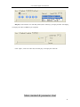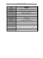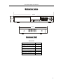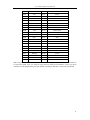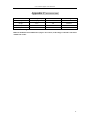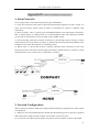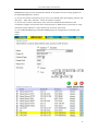
1
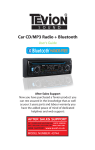
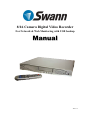
8/16 Camera Digital Video Recorder For Network & Web Monitoring with USB backup M anual Ver 1.0 8/16 Channel Digital Video Recorder Security Notice z Power supply This Digital-Video-Recorder uses DC 12 voltage indoor power supply. The voltage of the power must be verified before using. When the DVR is not in use for a long time, pull out the plug from the socket and disconnect the power. z Security This DVR is for indoor use only; in order to avoid the danger of a short circuit or electric shock, please do not expose the DVR to rain or a moist environment. If any solid or liquid enters the unit’s case, please turn off the power supply immediately, and ask for qualified technician to check the DVR before restart the unit. This DVR is precise instrument; do not attempt to repair any component of the DVR by yourself as this will void your warranty. If your DVR malfunctions in any way, please contact a dealer in your area or Swann Technical Support directly. z Installation Please choose appropriate site to install the DVR, to ensure well adequate ventilation around the DVR to avoid excessive heat. Do not install the DVR near a radiator, ventilating trunk, heat sources, under direct sunshine, dusty location, or anywhere there is a chance of mechanical librations or impact. Features of this DVR z z z z z z z z z z z z z z z z Video input: 8/16channels input; video output: 3 output. Audio input: 4channels input; audio output: 1 output Four optional levels of image quality: very high, high, normal, low. Record and playback frame rate changeable for recording. Compression mode: Modified MJEPG. Compatible with NTSC and PAL format. Support alarm recording and time recording. Multi-function searches: be able to distinguish different alarm records and time records from ordinary records; be able to search by time, by segment or by event. Support various playback modes: pause, several fast forward and backward play modes. Support zoom, auto function, watermark security 8/16 alarm input and 1 relay alarm output. Equipped with remote device, and PTZ control enable. Support loss and motion detection functions. Triplex operation, can play back and search play while it is recording. Support network view. Support USB backup and CD_RW backup. 480 frames (NTSC, PAL is 400) per second for view, 120 frames (NTSC, PAL is 100) per second for recording. 1 8/16 Channel Digital Video Recorder Table of Contents SYSTEM SETUP ..................................................................... 1 1. USING THE SETUP MENU .................................................................................................................1 2. ACCESSING THE MENU ...................................................................................................................1 3. SYSTEM SETUP ...............................................................................................................................2 4. TIME/DATE SET ..............................................................................................................................2 5. HDD FORMAT SET ..........................................................................................................................3 6. FACTORY RESET..............................................................................................................................4 7. CHANGE PASSWORD .......................................................................................................................4 8. FIRMWARE UPDATE ........................................................................................................................5 9. DISPLAY SETUP ...............................................................................................................................6 10. CAMERA NAME.............................................................................................................................6 11. COLOR SETUP ...............................................................................................................................7 12. AUTOSEQ SETUP ...........................................................................................................................8 13. RECORD SETUP .............................................................................................................................8 14. AUDIO CH SETUP ..........................................................................................................................9 15. REC CH SETUP ...........................................................................................................................10 16. NETWORK SETUP ........................................................................................................................10 17. N/W ENABLE SET .......................................................................................................................11 18. MAC SET.....................................................................................................................................12 19. SENSOR SETUP ............................................................................................................................12 20. MOTION DETECTION SETTINGS...................................................................................................13 21. AREA SET....................................................................................................................................14 22. SCHEDULE SET ...........................................................................................................................15 23. BACKUP SET ...............................................................................................................................16 24. STORAGE INFO ............................................................................................................................16 25. PROTOCOL SET ...........................................................................................................................17 BUTTONS ON THE FRONT PANEL ............................. 18 1. 2. 3. 4. 5. RECORDING/PLAYING CONTROL BUTTONS AREA ....................................................................18 FUNCTION CONTROL AREA(16 CH) ..........................................................................................18 FUNCTION CONTROL AREA(8 CH) ............................................................................................20 CHANNEL CHOOSING CONTROL AREA(16CH) ..........................................................................21 CHANNEL CHOOSING CONTROL AREA(8CH) ............................................................................22 SYSTEM CONNECTION ................................................... 23 1.BACK PANEL AND CONNECTION TERMINALS ................................................................................23 2.VIDEO AND AUDIO CONNECTION ..................................................................................................24 3.ALARM CONNECTION ....................................................................................................................25 4.HARD DISK CONNECTION..............................................................................................................26 2 8/16 Channel Digital Video Recorder QUICK USER GUIDELINE .............................................. 27 1.START THE DVR ............................................................................................................................27 2.TURN OFF THE DVR ......................................................................................................................27 3.NORMAL RECORDING ....................................................................................................................27 4.ALARM RECORDING ......................................................................................................................27 5.TIME RECORDING ..........................................................................................................................27 6.PLAYBACK .....................................................................................................................................28 7.SEARCH PLAY ................................................................................................................................28 8. TIME SEARCH ...............................................................................................................................30 9. EVENT SEARCH .............................................................................................................................31 10. START STOP SEARCH...................................................................................................................32 11.USB BACKUP ..............................................................................................................................32 12.CD_RW BACKUP ........................................................................................................................33 13.USB UPDATE ...............................................................................................................................35 14.ZOOM OPERATION .......................................................................................................................35 15.INFORMATION DISPLAY ...............................................................................................................36 16.PTZ OPERATION ..........................................................................................................................37 17.DEFAULT SETTING .......................................................................................................................38 18.REMOTE CONTROL ......................................................................................................................40 19. PC VIEW SOFTWARE OPERATION................................................................................................41 EXTERIOR SIZE .................................................................. 46 INCASE LIST ......................................................................... 46 APPENDIX A: TROUBLE SHOOTING GUIDE ................................... 47 APPENDIX B: PROTOCOL FOR DVR CONTROL .............................. 50 APPENDIX C: RECORD TIME TABLE ........................................... 53 APPENDIX D: INTERNET VIEW/PLAYBACK CONFIGURATIONS .......... 54 3 8/16 Channel Digital Video Recorder System Setup Before using the DVR, you must first set up the setup the system according to your needs and location; otherwise the DVR will run in the default settings which may be unsuitable for you. 1. Using the Setup Menu When in setup mode, pressing the up or down button, will move the cursor will through the various settings, continuous pushing will make the cursor move among the options one by one. The selected option will be highlighted in yellow. While choosing digital fields, e.g. year, month, day, hour, minute, second etc, push the left or right button, to move to the different digits of one field. Continuous pushing will make it move amoung digits one by one, and it can recur. Press the “Add” or “Dec” button to change the value that the cursor is highlighting, then push the “ENTER” button to enter sub menu and push the “Menu” button to return to previous menu. 2. Accessing the Menu If the DVR is in the recording mode, you can not access the menu unless you stop the recording first. Press the “Stop” button and enter the password to stop all functions, then press the “Menu” button. The password can be a combination of 4 digits of “0-9”. The default is “0000”. To enter the menu, you must input the correct password by pushing the digit buttons. If the password you have inputted is incorrect, the system will automatically return to the main screen. If you want to cancel the input of the password, you can push the Menu button to return to the main screen again. While inputting the password, in order to avoid being revealed to bystanders, the password you input is displayed on the screen as “*” signs. To change the password, please refer to the “password change” section. 1 8/16 Channel Digital Video Recorder 3. System Setup When the cursor moves to System Setup, please push the enter button and the System Setup window will appear, which is illustrated as below. MENU LANGUAGE: language set of the DVR, push “Add” or ”Dec” to change language. VIDEO SOURCE: switch the video format to suit the TV standard of your country, NTSC or PAL BUZZER SOUND: buzzer switcher, if set to “OFF”, the buzzer will not work.. If motion detection is enabled, the buzzer will sound when motion is detected. 4. Time/Date Set When the cursor moves to TIME/DATA SET, push the Enter button and the Time/date set window will appear as illustrated as below. 2 8/16 Channel Digital Video Recorder . Please push up, down, left, and right buttons to move the cursor, press ADD and DEC button to modify the value. FORMAT: the date display format, which can be different for USA, EURO and Australian users. DISPLAY: if set to “OFF”, the time will not display no the screen. LOCAL: time display position on the screen. 5. HDD Format Set When the cursor moves to HDD FORMAT SET, please push the Enter button and the HDD Format Setup window will appear, which is illustrated below. If you select “YES” and press the enter button, all video files on the HDD will deleted. If you do not want to delete all recording, please select “NO”. 3 8/16 Channel Digital Video Recorder 6. Factory Reset When the cursor moves to System Setup, push the enter button, and the Factory Setup window will appear. If you select “YES” and push the enter button, all the DVR settings will reset to default, if you do not want to reset to default settings, please select “NO”. 7. Change Password When the cursor moves to Change Password, please push the enter button, and the Password window will appear. Password Level: password type of the DVR, the DVR has various types of password: SETUP: If set to “YES”, you have to input password to enter menu. SYSTEM: If set to “YES”, you have to input password to boot the DVR. RECORD: If set to “YES”, you have to input password to stop manual recording. SCHEDULE: If set to “YES”, you have to input password to cancel schedule recording. 4 8/16 Channel Digital Video Recorder If you select the Password Change and push the Enter button, the Password change window will display as below: Please enter the current password, then input new password and confirm the password. 8. Firmware Update When the cursor moves to Firmware update, please press enter button, and the update window will appear. Update Method: There are two methods to update the DVR firmware, USB (for USB thumb drives) and Network (not support) USB update: create a new folder named “firmware” in the USB thumb drive’s root directory, copy the update file to the folder, plug in the USB thumb drive. Enter the Firmware Update menu, select Update Start and press enter button, the system will start updating. When updating is finished, the window below will be displayed, please manually reboot the DVR. 5 8/16 Channel Digital Video Recorder 9. Display Setup When the cursor moves to Display Setup, please push the Enter button, the Display Setup window will appear. 10. Camera Name When the cursor moves to Camera Name, please push the Enter button, the Camera Name Setup window will appear. 6 8/16 Channel Digital Video Recorder Press the up or down button to select channels, press the Enter button to change the channel name. Each channel’s name is the combination of eight characters. Press left or right button to select each character, press ADD or DEC button to modify each character, and then press enter button to save this name. DISPLAY: if Display is set to “OFF”, the channel’s name will not display on the screen. 11. Color Setup When the cursor moves to Color Set, please push the Enter button, the Color Setup window will appear. CON: picture contrast BRI: picture brightness HUE: picture hue SAT: picture saturation 7 8/16 Channel Digital Video Recorder Press left or right button to select CON/BRI/HUE/SAT, press ADD or DEC to change the value, if setup over, press ADD or DEC to change channel. 12. Autoseq Setup When the cursor moves to Autoseq Set, please press enter button, the Auto Sequence Setup window will appear. Press the up or down button to select channel, press ADD or DEC button to change the auto Sequence time. 13. Record Setup When the cursor moves to Record Setup, then push the Enter button, the Record Setup window will appear, which is illustrated as below. Press up or down button to move the cursor. Then push the “ADD”or “DEC” button to change the value. While the DVR is in recording or playback mode, 8 8/16 Channel Digital Video Recorder you cannot access this menu unless you stop record or play first. OVER WRITE: if set to “YES”, the DVR will automatically overwrite the HDD from the beginning when the HDD is full. If set to “NO”, the DVR will automatically stop recording when the HDD is full. If there are two HDD in the DVR, when the MASTER HDD is full, the video will store to the SLAVE HDD, and when the SLAVE HDD is also full, the DVR will overwrite the MASTER HDD if set this to yes, otherwise it will stop recording. REC SPEED: the recording frame rate of the DVR, factory default setting is 30F/SEC under NTSC (25F/1SEC under PAL). This means the DVR records the events at the speed of 30 shots of frames per second. The higher of the record frame rate, the more natural look will be displayed on the screen when you playback the footage. The lower of the record frame rate, the more you can save the space on the hard disk. The highest frame rate is 120F/SEC(PAL is 100F/SEC) when the resolution is in 320 mode REC QUALITY: There are four different video quality settings: VERY LOW, LOW, NORMAL, HIGH. The higher of the video quality, the clearer images you can get when you playback. The lower of the video quality, the more you can save the space on the hard disk drive. RESOLUTION: the record picture size of the DVR have two modes: 360 and 720, default is 360. In 720 mode, the recorded picture is twice the size of that in 360 mode. In 360 mode the REC speed is 120F/SEC NTSC (PAL is 100F/SEC) and the maximal REC speed in 720 mode is 60F/SEC NSTC (PAL is 50F/SEC). PB SPEED: the frame rate of playback, default is NO USE, which means the same as record. 14. Audio ch Setup When the cursor moves to Audio CH Set, push the Enter button, the Audio CH Setup window will appear, as illustrated below. There are four audio input channels, for each channel you can select anyone of the 16 channels. Although there are four audio input channels, you can only record from one channel’s audio at the same time. To setting the audio correctly, you have to select one channel within these four channels in the Record Setup menu. 9 8/16 Channel Digital Video Recorder 15. REC ch Setup When the cursor moves to REC ch Set, please press enter button, the REC ch setup window will appear. This screen is different for 720 size and 360 size. In 720 size, the window is illustrated as below, press upward and downward buttons to select channel and press ADD or DEC button to change the setting, If the channel is set “OFF”, this channel will not record when in recording mode. If the resolution is set to 360 size, the REC ch Setup window can not be setup. 16. Network Setup When the cursor moves to Network Setup, push the Enter button, and the network setup menu window will appear. Please note if the Netviewer software is connected to the DVR. You cannot access this menu unless you close the Netviewer software. 10 8/16 Channel Digital Video Recorder IP MODE: the DVR has 2 IP mode, STATIC IP and DHCP, if you select STATIC IP, you can set the IP address manually, if you select DHCP mode, the DVR will automatically get the IP address. For STATIC IP, press upward, downward, leftward or rightward button to move the cursor among the digits, you can press ADD and DEC button to modify the digits, also, when selecting a digit, you can press enter button then press left or right button to select each digit, and then press ADD or DEC button to modify this digit, press enter to save you change. NETWORK ENV: the DVR has three types of different network conditions: LOCAL, EXTER_LAN, EXTER_WAN. If in local network, please select LOCAL. If for internet use, please choose EXTER_LAN. If the internet condition is not very good, please select EXTER_WAN. VIDEO PORT: the video transmit port for the computer. Default is 5000. COMMAND PORT: the command transmit port for the computer. Default is 5001. If you change any of the VIDEO PORT and COMMAND PORT or MAC address, you have to restart the DVR before you use the “net viewer” software. Note: if you have change the MAC address, you can not see the “MAC ADDR SET”. 17. N/W Enable Set When the cursor moves to N/W Enable, push the Enter button, and the N/W Enable setup window will appear. 11 8/16 Channel Digital Video Recorder If one channel here set OFF, this channel will not transmit to the network, so if you want to see a channel from network, you must to set this channel ON. 18. Mac Set When the cursor moves to Mac Set then push the Enter button, the Mac Set window will appear. If you have more than one DVR in a local area network, you have to set each DVR to have an exclusive MAC address, but remember that you have only one chance to modify the MAC address, once you have changed the MAC address, this menu will not appear again. If you want to change the MAC address again, please load the factory set, then you can change the MAC address. For MAC address, you’d better set the first two bytes to “00 00”, and change other bytes. 19. Sensor Setup When the cursor moves to Sensor Set, then push the Enter button, the sensor setup window will appear. Press up or down button to move the cursor. Press “ADD” or “DEC“ to change the value. 12 8/16 Channel Digital Video Recorder ALARM ENABLE: alarm trigger switch, can be set to off, low lever or high lever. If users set it to off, the DVR will ignore the alarm input. MOTION ENABLE: Motion alarm switch, can be set to ON or OFF. If set to off, the motion alarm. MOTION LEVEL: motion sensitivity level, if the figure in the picture is small, please set to high or very high, default is normal. BUZZER TIME: buzzer sound time when there is a sensor or motion alarm. SENSE RECTIME: when a motion or sensor alarm is triggered, the recording time of DVR, default is 1 minute. If alarm and motion recording if not enabled, the value will be set to OFF. Note: Users should press Schedule button after setting up the parameters so to activate the settings. 20. Motion Detection settings 1) When surveying nearby objects (2-10 meters) When in daytime, please set motion detection sensitivity to Normal level; when in night, please set to low. 2) When surveying objects in 50-100 meters area The objects 50-100 meters away will be quite small on the screen. When in daytime, please set motion detection sensitivity to high level. 13 8/16 Channel Digital Video Recorder When in night as below, please set to normal level. Note: the above suggestions are a guide only based on testing in a general environment. You will need to select the best parameters according to the actual operation environment you are covering. Try different settings until you get the desired motion detection result. 21. Area Set Move the cursor to Alarm Set, then push the Enter button, and the alarm setup window will appear. Push the up, down, left, right button to move the cursor and press the Enter button to change from detection ON to OFF. Push and hold the Enter button to change all values to the same as the area you have selection. 14 8/16 Channel Digital Video Recorder If the area marker icon is set to yellow, this area is monitored for motion detection, and if the icon is grey, motion sensing is disabled for that area. 22. Schedule Set When the cursor moves to Schedule Set, push the Enter button, and the schedule setup window will appear. You can change a recording schedule during a week by using this setup windows. Please note: Military time must be used. START: start record time STOP: stop record time Note: Manual record mode and schedule record mode (including motion detection record mode, sensor record mode and time schedule record mode) can not be used at the same time. Once the user selects Schedule record mode, manual record mode will disabled; once user select manual record mode, schedule record mode will be disabled. 15 8/16 Channel Digital Video Recorder 23. Backup Set When the cursor moves to Backup Set, push the Enter button, and the backup setup window will appear. There are two types of backup modes, USB and CD_RW(not included in this model). If you select USB backup, plug in the USB device, and push the Enter button, you should see the screen below. There are two types of backup mode: STILL and MOVIE, in STILL mode you can backup pictures and in MOVIE mode you can backup video. Press ADD or DEC to change the backup mode. Please refer to USB Backup for more information. For CD_RW backup, please refer to CD_RW backup. 24. Storage Info When the cursor moves to Backup Set, push the Enter button, and the backup setup window will appear. 16 8/16 Channel Digital Video Recorder 25. Protocol Set You must set the correct protocol so you can control a Pan Tilt camera (Speed Dome) via the DVR. Move the cursor to Protocol Set, then push the Enter button, and the protocol set window will appear. Push the up or down button to move the cursor, and press “ADD” or “DEC“ to change the value. CHANNEL SEL: If you have a speed dome camera, select the channel which the camera is connected to. BAUDRATE: Changeable from 1200bps to 19200bps. The default value is 2400bps. DOME ADDR: The address of the speed dome camera, changeable from 0x00 to 0xff. PROTOCOL: The protocol of speed dome camera: pelco-p, pelco-d, neon, or lilin. DVRPROTOCOL: The protocol used by the computer or keyboard to control the DVR, please refer to appendix A DVRADDRESS: The address of the DVR for DVRPROTOCOL, can be changed from 0x00 to 0xff DVRBAUDRATE: The baud rate of the DVR for DVRPROTOCOL. 17 8/16 Channel Digital Video Recorder Buttons On the Front Panel The front view of the video-recorder is illustrated as below. 1. Recording/Playing Control Buttons Area 1. Record: This is the manual recording button. Push this button to record, Re-push this button or push the stop button to stop recording (enter your password to confirm). Recording and stop will work simultaneously on all 16 channels. This button doesn’t work in schedule mode. 2. Play: Push this button to start playing the video stored in hard disk, Re-push this button or push the stop button to stop playing. Playing and stop will work simultaneously on 16 channels. This button doesn’t work during Time recording and Alarming recording. 3. Rew: Fast rewind button. Push this button to start fast rewind playing. Push the play button again to start playback at normal speed. 4. Forward: Fast forward button. Push this button to start fast forward playing. Push the play button again to start playback at normal speed. The fast forward has five speeds; every time you push the button, the play speed will increase from slow to fast and then back to slow. 5. MODE: Mode change key, press this key to switch to shift mode, re-press to change to normal mode. 2. Function Control Area(16 ch) 18 8/16 Channel Digital Video Recorder 1. Auto/1: Auto key, in shift mode, press this button, The DVR will be in auto dwell state, it dwells according to the time set in auto sequence set menu, you can set the dwell time of each channel. Press this button to quit this mode. If not in shift mode, press this button to see big picture of channel 1. While inputting numbers, this button is used as number key of “1”. 2. Zoom/2: Zoom key, in shift mode, press this button, the DVR will be in zoom mode, please refer to zoom operation in user guideline for details, press zoom button again to cancel zoom operation. If not in shift mode, press this button to see big picture of channel 2. While inputting numbers, this button is used as number key of “2”. 3. PIP/3: USB key, in shift mode, press this button, the DVR will start USB backup, please refer to USB backup operation in user guideline for details. If not in shift mode, press this button to see big picture of channel 3. While inputting numbers, this button is used as number key of “3”. 4. Display /4:Display key, in shift mode, press this button to display current information on the screen, press again this to clear the information display. If not in shift mode, press this button to see big picture of channel 4. While inputting numbers, this button is used as number key of “4”. 5. Freeze/5: Freeze key, in shift mode, press this button, the DVR will be in freeze mode, please refer to freeze operation in user guideline for details, re-press this button to quit freeze mode, If not in shift mode, press this button to see big picture of channel 5. While inputting numbers, this button is used as number key of “5”. 6. Schedule/6: schedule key, in shift mode, press this button to enter schedule state, if the DVR is in schedule state, there will be a “S” symbol on screen, press again this button to quit schedule mode. If not in shift mode, press this button to see big picture of channel 6. While inputting numbers, this button is used as number key of “6”. 7. ADD/7/: Add key, press this button to see big picture of channel 7. When in system setup menu, this is an increase button. While inputting numbers, this button is used as number key of “7”. 8. DEC/8/: Decrease key, press this button to see big picture of channel 8. When in system setup menu, this is a decrease button. While inputting numbers, this button is used as number key of “8”. 9. SR/9: Single frame backward button, in shift mode, while in playback state, long press this button can see single frame backward, press play button to play normally. If not in shift mode, 19 8/16 Channel Digital Video Recorder press this button to see big picture of channel 9.While inputting numbers, this button is used as number key of “9”. 10. SF/0/10: Single frame forward button, in shift mode, while in playback state, long press this button can see single frame forward, press play button to play normally. If not in shift mode, press this button to see big picture of channel 10. While inputting numbers, this button is used as number key of “0”. 11. WM/10+: Watermark button, In shift mode, if the DVR is playing video, you can press this button to see the watermark of the picture, if the video was recorded by this DVR and has not be changed, there will be a watermark symbol in each picture, press watermark key again to clear the display. If not in shift mode, press this button and then press 1 to 6 to see big picture of channel 11 to channel 16. 12. Menu/search: press this key to enter search menu, long press this key to enter menu(need password), if in menu setup, press this key to quit current menu. 3. Function Control Area(8 ch) 1. Auto/1: Auto key, in shift mode, press this button, The DVR will be in auto dwell state, it dwells according to the time set in auto sequence set menu, you can set the dwell time of each channel. Press this button again to quit this mode. If not in shift mode, press this button to see big picture of channel 1. While inputting numbers, this button is used as number key of “1”. 2. Zoom/2: Zoom key, in shift mode, press this button, the DVR will be in zoom mode, please refer to zoom operation in user guideline for details, press zoom button again to cancel zoom operation. If not in shift mode, press this button to see big picture of channel 2. While inputting numbers, this button is used as number key of “2”. 3. USB/3: USB key, in shift mode, press this button, the DVR will start USB backup, please refer to USB backup operation in user guideline for details. If not in shift mode, press this button to see big picture of channel 3. While inputting numbers, this button is used as number key of “3”. 4. Freeze /4:Freeze key, in shift mode, press this button, the DVR will be in freeze mode, please refer to freeze operation in user guideline for details, re-press this button to quit freeze mode. If 20 8/16 Channel Digital Video Recorder not in shift mode, press this button to see big picture of channel 4. While inputting numbers, this button is used as number key of “4”. 5. Stop/5: Stop key, in shift mode, press this button, the DVR will stop record and play. If not in shift mode, press this button to see big picture of channel 5. While inputting numbers, this button is used as number key of “5”. 6. WM/6: Watermark button, In shift mode, if the DVR is playing video, you can press this button to see the watermark of the picture, if the video was recorded by this DVR and has not be changed, there will be a watermark symbol in each picture, press watermark key again to clear the display. If not in shift mode, press this button to see big picture of channel 6. While inputting numbers, this button is used as number key of “6”. 7. ADD/7/: Add key, press this button to see big picture of channel 7. When in system setup menu, this is an increase button. While inputting numbers, this button is used as number key of “7”. 8. DEC/8/: Decrease key, press this button to see big picture of channel 8. When in system setup menu, this is a decrease button. While inputting numbers, this button is used as number key of “8”. 9. Display/9:. Display key, in shift mode, press this button to display current information on the screen, press again this to clear the information display. If not in shift mode, press this button to see big picture of channel 9.While inputting numbers, this button is used as number key of “9”. 10. Schedule/0: Schedule key, in shift mode, press this button to enter schedule state, if the DVR is in schedule state, there will be a “S” symbol on screen, press again this button to quit schedule mode. If not in shift mode, press this button to see big picture of channel 10. While inputting numbers, this button is used as number key of “0”. 11. Menu: Menu key, press this button to enter system setup menu, in menu setup mode, press this button to save settings and quit current menu. 12. Search: Search key, press this button to enter search menu, please refer search play in user guideline for details. 4. Channel Choosing Control Area (16ch) 21 8/16 Channel Digital Video Recorder 1. Big picture/up: Press this button to see full screen, re-press this button to see the next channel. While selecting menu items, press this button to move up the cursor. 2. Four pictures/down: Press this button to see four pictures display, re-press this button will display next four pictures. While selecting menu items, press this button to move down the cursor. 3. Nine pictures/left: Press this button to see nine pictures display, re-press this button to see eight pictures. While selecting menu items, press this button to move the cursor leftward. 4. Sixteen pictures/right: Press this button to see sixteen pictures display, re-press this button to see thirteen pictures. While selecting menu items, press this button to move the cursor rightward. 5. Enter: While selecting menu items, press this button to select the item. While playing video, press this button to pause the play, press play button to continue play. 5. Channel Choosing Control Area (8ch) 1. Big picture add/up: Press this button to see full screen, re-press this button to see the next channel. While selecting menu items, press this button to move up the cursor. 2. Big picture dec/down: Press this button to see full screen, re-press this button to see the preview channel.. While selecting menu items, press this button to move down the cursor. 3. Four pictures/left: Press this button to see four pictures display, re-press this button to see next four pictures. While selecting menu items, press this button to move the cursor leftward. 4. Eight pictures/right: Press this button to see eight pictures display. While selecting menu items, press this button to move the cursor rightward. 5. Enter: While selecting menu items, press this button to select the item. While playing video, press this button to pause the play, press play button to continue play. 22 8/16 Channel Digital Video Recorder System Connection 1. Back Panel and Connection Terminals The power cable and input, output signal terminals are all at the back of the machine, the connections to monitor, camera etc equipments are all carried out through the terminals and sockets on the back panel. The back view of the machine is illustrated as below. Take 16 ch for example, 8 ch is much the same as 16 ch. Each part of the back panel is illustrated as below: 1. video input 1-16 2. main output 3. assistant monitor 4. s video 5. audio input 6. audio output 7. net interface 8. USB port 9. alarm and RS485 port(see below) 10. debug port 11. fan 12. power Alarm and RS485 port define: 1---12: sensor 1---sensor 12 13,20,24,25: GND 14---17: sensor 13---sensor 16 18: RS485A 21: COM 19: RS485B 22: NC 23: NO 23 8/16 Channel Digital Video Recorder 2. Video and Audio Connection The DVR can support up to 16 cameras video input at the same time. There are two steps for camera installation. I. Connect the Video Signal Line to the DVR channel input. II. Connect the power adaptor jack to the camera. The DVR can connect 4 channel’s audio input, but you can only select one for recording. To display the DVR image, the DVR’s video output signal should be displayed to your TV set or monitor. Any TV set that has a “video input” terminal is suitable for displaying the image. The figure above shows the video and audio signal line connection. Note: at one time, you can only connect one audio input, which means, if you connect an audio to cam1, you cannot connect anyone else from cam2 to cam 4. 24 8/16 Channel Digital Video Recorder 3. Alarm Connection The DVR can support 16 alarm input and 3 alarm output. Alarm input: There are two types of alarm input. 1. Voltage output(5V and 0V) A: In case sensor output high voltage (5V) normally and output low voltage when triggered (0V), then users must set DVR as low voltage alarm. B: In case sensor output low voltage (0V) normally and output high voltage when triggered (5V), then users must set DVR as high voltage alarm. Please refer to the picture below, channel 2 to channel 16 are the same as channel 1. 2. Open/Close output A: N.O. Normal open, close when triggered. DVR must set as low voltage alarm. B: N.C. Normal close,open when triggered,DVR must set as high voltage alarm. Please refer to the picture below, channel 2 to channel 16 are the same as channel 1. Alarm output There are three alarm output pin, the status of these pin are illustrated as below After alarm Before alarm N. O. COM N. C. N. O . COM N. C. There is an example for alarm output connection N. O. COM N . C. Alarm 5V 25 8/16 Channel Digital Video Recorder 4. Hard Disk Connection 1. Open the cover of the hard disk enclosure and unlock it using the supplied key. When unlocked the key will be vertical as shown. 3. Slide the top cover of the caddy towards the back (the end with the connector) and remove it. 2. Carefully lift the handle on the front of the caddy and remove it from the housing. 4. Prepare your hard drive by setting the jumper to Master. Check the label of the hard drive for information on how to do this. 5. Place your hard drive in the caddy and then connect the data cable to the socket on your hard drive. 6. Connect the power connector to the power socket on your hard drive. The connector fits with the cut off corners at the top. 7. Slide the top cover of the caddy towards the end with the handle to replace it. 8. Replace the caddy into the housing pushing on both sides to ensure a solid connection, then turn the key to the horizontal position to lock it. Please note: For instructions on how to jumper your hard disk drive (HDD) to “master”, please refer to the information found on the label on top of the hard drive or visit the hard disk drive manufacturers website. Also note that the key must be in the locked position for the hard disk drive to work. If the key is left in the unlocked position the power to the hard drive is switched off. Note: If the DVR comes with a CD-RW, please fellow the below steps. Open the DVR cover, fix the HDD to the DVR HDD shelf of soleplate, then connect the power and digit cable. If you have another HDD, please jump the first one to MASTER and the other to SLAVE, put that HDD on the other HDD shelf, and then connect the power and digit cable. 26 8/16 Channel Digital Video Recorder Quick User Guideline 1. Start the DVR Before starting the DVR, please make sure all the items in the “Security Notice” at the beginning of this manual are fulfilled and that the input and output cables are all correctly connected. Also ensure the DVR’s video input format (NTSC/PAL) and the monitor (NTSC/PAL) are both set to the same video standard. NTSC for USA & Canada, PAL for Australia, UK and most of Europe. Fit the hard disk to the removable caddy and insert the removable caddy into the housing, then lock it up (turn the hard disk lock to the right) and connect the power which will then boot the DVR and it will start to work. 2. Turn off the DVR Only turn off the DVR when the system is inactive. Do not to turn off the DVR while playing or doing the System Setup. Turning off the DVR while recording may cause the recording to corrupt, and can cause the HDD to be unreadable in some cases. Push the Record button to stop recording or push Stop button to stop playing or exit from System Setup menu, then turn off the power. If do not wish use the video recorder for a long time, you should pull out the power line from the electrical outlet and store the unit where it will not be damaged. 3. Normal Recording Connect the power to all related equipment; ensure that there is video input using direct connection to your TV or VCR. Push the Display button to check spare space of the hard disk, if there is not much space, please consider changing your hard disk first or select Overwrite mode. Check recording parameter setup before recording; select video quality, frame rate. Note that you cannot change record setting during the process of recording. Manual recordings are the normal recording condition. Under the manual mode (non-schedule status), pushing the Record button will record all channel’s video. Push the Record button to begin recording, four channels will start simultaneous recording. While in normal recording mode, push the Record or Stop button, and enter the right password, to stop recording. During the process of recording if the hard disk is full and the system is set to automatic overwrite, the recording will not be interrupted but the DVR will automatically begin to overwrite recorded video from the earliest (oldest) recorded area. If the system is set to overwrite disabled, it will stop recording once the HDD is full. 4. Alarm Recording Alarm recording is not started by manually pushing the Record button, it is automatically activated once Schedule mode is enabled. Alarm recording can be activated by alarm input signal or motion, if the connection of alarm input equipment is correct, stable and reliable, and the alarm settings are correct. For recording to be activated by exterior input signal or motion detection the system must be set to 27 8/16 Channel Digital Video Recorder Schedule Mode active and that period is set to “A” in Record Schedule setup. You must also set the menu of Alarm Setup for exterior input alarm, and the alarm enable setting of that channel must be set to “ON”. For Motion Alarm, the motion enable setting of that channel must set “ON”, and set the area for motion detection must be set. If Schedule mode is disabled the system will not start recording on alarm. Setting schedule on or off is achieved through pushing the SCHEDULE button on the front panel or remote, but not through the System Setup menu and window. When the unit is in Schedule Mode active, the character “S” will display on the screen. Alarm video recording can’t be stopped by pushing the RECORD or STOP button while Schedule Mode is active. To ensure that once Schedule Mode is set to on that the schedule cannot be accidentally stopped there is a password protection to stop Schedule Mode. You must press the SCHEDULE button then enter the correct password to turn Schedule Mode off. Check Alarm Recording setup before recording; confirm the video quality and the frame rate, as the record setting can’t be changed during the recording process. As long as the alarm input signal is correctly set the alarm recording will continue during the period of time set up by A/M REC TIME, and when the outside the time period the alarm recording automatically stops. 5. Time Recording Time recording starts and stops recording automatically according to the pre-arranged time period. It is applied to a fixed timetable, for example business hours time recording (or outside business hours time recording) with fixed start/stop time. To start the Time Recording function you must have a record schedule setup beforehand. When this is done, push the SCHEDULE button on the front panel to set schedule mode to on and the schedule symbol “S” will display on the screen. The Time Recording mode will not work unless you activate Schedule Mode. To make Time Recording mode active the system must be set to Schedule Mode active and that period is set to “T” in Record Schedule setup. In Time Record mode, you must push the SCHEDULE button then enter the password to stop time recording. Because Time recording is reliant on the system being set with the correct time, you must adjust the time to your correct local time before using this function. 6. Playback Push the PLAY button and the system will begin to play the images recorded from the start of the most current recording. If the recording is playing, push the PAUSE button to pause playing, push the PLAY button again to resume normal play. To use Fast Forward playing or Fast Backward playing, push the FORWARD or REW button while the recording is playing to see faster playback. Push the PLAY button to return to normal speed playing from the current place. Continuous pushing of the FORWARD button will change the fast-forward between five levels of speed (X2, X4, X8, X16, X32) in sequence. Continuously pushing the REW button will change the fast backward playback between four levels of speed (X2, X4, X8, X16) in sequence. 28 8/16 Channel Digital Video Recorder During playback mode, press the Single Frame Forward button to play a frame at a time, and hold the button in to continually play one frame at time while the button is held. During playback mode, press the Single Frame Rewind button to play back a frame at a time, and hold the button in to continually play one frame at time while the button is held. Push the PLAY button again to resume normal playback speed, or push the STOP button to stop playing. 7. Search Play Push the search button to display the Search play window on the screen. TIME SEARCH: search recording to the time entered. EVENT SEARCH: search recording by event list. START STOP SEARCH: search recording by segment. Press the up or down buttons to move cursor, then press Enter button to enter sub menu you have highlighted. Push the Search button again to quit from search menu. 29 8/16 Channel Digital Video Recorder 8. Time Search Move the cursor to Time Search, then push the Enter button and the Time search window will appear, as illustrated as below. The red block below the number means there is recorded video at that time. Push the left and right buttons to move the cursor along the year, month, day, hour and minutes. Push the ADD and DEC buttons to modify the date and time. Please note: You can only view footage that has been recorded. Therefore you must select time and dates that have a red block below them. 30 8/16 Channel Digital Video Recorder 9. Event Search Move the cursor to Event Search, and then push the Enter button, the event search window will appear, which is illustrated as below. There are four types of event on this list: MOTION, ALARM, SCHEDULE and NETWORK. MOTION means motion triggered alarm recording. ALARM means external sensor triggered alarm recording. SCHEDULE means scheduled time recording. NETWORK means network activated recording. Press the up or down buttons to move the cursor along the event list, push the left or right buttons to see previous or next page, and push the Enter button to play the segment you selected. Push the search button to return to the Search Play menu. If you want to change the between the MASTER HDD and SLAVE HDD, push the mode button, then press Enter button. Push the Menu button to exit. 31 8/16 Channel Digital Video Recorder 10. Start Stop Search Move the cursor to the Start Stop Search, push the Enter button, and the Start stop search window will appear. All recorded segments are displayed here, push the up or down buttons to move the cursor along the segment list, press left or right buttons to see previous or next page, push the Enter button to play the segment you selected. Press search button again to return to the Search Play menu. If you want to change the between the MASTER HDD and SLAVE HDD, push the mode button, then press Enter button. Push the Menu button to exit. 32 8/16 Channel Digital Video Recorder 11. USB Backup Plug in the USB device, go to the menu of Backup set, check whether the USB device was detected, and there is enough free space of the USB device, select the backup mode, then completely exit the menu system. USB backup is available only in playback mode. If you selected “STILL” for the backup mode, press the USB button and an “S” will appear on the screen. When it disappears, the backup of the picture is finished, and you can un-plug the USB device out and see the picture on a computer with the net viewer software. If you select “MOVIE” for the backup mode, press and hold the USB button until the “A” appears on the screen, press the USB button again to select the end of the backup video. This may take a little time, and make sure the USB device has enough free space, if the “A” disappears, the backup is ok, and you can view the video on a computer with net viewer software. NOTE: if you backup still picture, please choose full picture display. We recommend using high quality USB thumb drives like Sandisk or Legend (Australia only) with the DVR. For long duration backups, we recommend saving the footage to VHS tape using a VCR. 12. CD_RW Backup This function is only selectable, if your DVR came with a CDRW. If you enter CD_RW backup menu, you will see the screen below: Start Time Set: you can set the backup start time: START: backup start time. END: backup end time. Backup Start: start backing up with CD_RW. If you select Start Time Set and press enter button, the Backup Start Search window will appear, which is illustrated as below: The operation is the same with time search, please select the start time you want to backup. 33 8/16 Channel Digital Video Recorder If you have selected the start backup time, then you have to change the backup size, here you can change the backup size you want from 1M to 650M. After these steps, you can insert your blank CD into the CDROM and select Backup Start, you can see the screen below: If backup finish, you can use the net viewer soft’s DriveScan function to see the video on CD. If the cd has been writed, press usb button to format the cd. 34 8/16 Channel Digital Video Recorder 13. USB Update Using your PC, create a folder called “firmware” in the root directory of your USB thumb drive, copy the update files to the folder. Plug the USB device into the DVR, go to the menu of Backup set, check that whether the USB device was detected, go to the Firmware Update menu and select USB method, move to Update Start and press Enter button and the update will start. If you see screen below, update was successful. Then reboot the DVR. NOTE: do not shut down the DVR when the DVR is updating, this may cause fatal problem. 14. Zoom Operation In shift mode, press zoom button, the DVR will be in zoom mode, which is illustrated as below. Press upward, downward, leftward or rightward to move the zoom area, then press enter button to zoom, press zoom button again to cancel zoom operation. 35 8/16 Channel Digital Video Recorder 15. Information Display In shift mode, press display button, the main information of the DVR will display on screen. HDD SIZE: the size of the hard disk HDD USED: the used space of the hard disk. HDD READ: current HDD address for playback OVERWRITE: overwrite time of the HDD NETWORK IP: IP address of the DVR. REC LIST: number of record list EVENT LIST: number of event list REC OVER: record list overwrite or not 36 8/16 Channel Digital Video Recorder EVENT OVER: event list overwrite or not. S/W VER: software version 16. PTZ Operation This DVR can control all speed domes which are connected to the DVR. To control the speed dome, make sure all the lines are correctly connected, first you must set the right protocol, baud rate, and speed dome’s address for each speed dome, please refer to protocol set. For example, you connect the first speed dome to channel one, you should make sure that the baud rate, the protocol, and speed dome’s address is the same as the speed dome you connect to the channel. PTZ can only be operated by remote device, press the PTZ button on the remote device, “PTZ” will be display on the screen, then select 1 to 16 to choose PTZ channel, the channel number will be displayed after “PTZ”, please refer to the picture below: You can press up, down, left, or right buttons to move the speed dome, and press the Enter button to stop. If you press the Iris button, the character “Iris” will appear on the screen, please refer to the picture below, then you can press the “ADD” and “DEC” button to change the iris, the same to control the focus, zoom, and speed, also press enter button to stop. 37 8/16 Channel Digital Video Recorder Press the PTZ button one more time to exit from PTZ control. 17. Default Setting Default setting for each item is shown in the below chart. “Defaults” is the initial setup by the manufacturer. User can change the setup according to the actual environment and demands. If there is any confusion or unexpected effect, choose “Defaults” and readjust. You can choose “FACTORY RESET” in “SYSTEM SET” menu, and reset all settings to default setting. item General setting S Y S T E M Recording Para S E T U Net Work Setting Setup items Default setup Selectable setup Year/Month/Day/ Hour/Minute 2005/01//01 12/00/00 2000~2099/Common sense rules Auto Time 1 second 0~99second Buzzer Sound ON ON/OFF Password 0000 N/A Play Repeat YES YES/NO Video Input NTSC format NTSC/PAL Quality Normal Very high/High/Normal/Low Overwrite Enable YES YES/NO Rec Speed 60f/s(NTSC) 50f/s(PAL) 120f/s~1f/2s(NTSC) 100f/s~1f/2s(PAL) Resolution 360 360/720 PB Speed NO use 120f/s~no use(NTSC) 100f/s~no use(PAL) Audio Enable CAM 1 CAM1~CAM16/OFF A/M REC Time 1 Minute 1~99minute Sub Net 255.255.255.0 N/A Gate Way 192.168.1.1 N/A 38 8/16 Channel Digital Video Recorder P Alarm setting Protocol Setting IP Address 192.168.1.111 N/A Net Work Speed Fast Fast/Normal N/W Enable ON ON/OFF Mac Address 0a0b0c0d0e0f N/A Alarm Enable OFF ON/OFF Motion Enable OFF ON/OFF Motion Level Normal Very low/Low/ Normal/High/Very high Buzzer Sound No Use 0~99 second Schedule setting OFF OFF/ON Baud Rate 2400 2400/4800/9600/19200/38400 Protocol PELCOP PELCOP/PELCOPD/ LILIN/ NENO Address 01-16 0~0xff 39 8/16 Channel Digital Video Recorder 18. Remote Control All the function of the DVR can be operated by the remote device. 40 8/16 Channel Digital Video Recorder 19. PC View Software Operation Use the PC View software, you can view the DVR through Internet, also, you can view and backup the video information on the HDD through a computer. Open the software, you will see the window below: Please click “Setting” button, you will see the window below: Enter the IP address and click “OK” button. 41 8/16 Channel Digital Video Recorder Click connect button, enter password, the password is the same as the DVR’ password. then click the OK button, if connect to the DVR, you can see the picture below. Click the “Confirm” button. When users survey by Internet, they should firstly open ports 5000-5002 (default and can be changed on the DVR) on the router side. Please learn more about how to do from the manual of router. 1. Play: if you select this, you will start to play the video on the DVR. 2. Stop: if you select this, you can stop the play. 3. AVI: if you select this, you can save the picture to AVI format on you computer. 4. LOCAL: you can save the video in you computer, and open with this software. 5. Live: you can select this button to see live picture, just click the play button. 6. Playback: you can view the playback video in the DVR 42 8/16 Channel Digital Video Recorder 7. ScanDisk:.if you select this, you can view the video on the HDD or CD which recorded in the DVR and then connect to the computer. 8. File Play: you can play the video file on the computer. AVI Save: when play video, click “AVI” button, the video will save as AVI format on the computer, you can play the file with any media player supports. Local: when video is playing, click “Local” button, the video will save to the computer, you can play the file with this software, please refer to File Play. Live Operation: if the software is in live mode (click Live Play), then click “Play”, it will connect to the DVR, and the live pictures will be transmitted to display on the window. Click “Stop”, it will stop transmitting pictures. Net Search operation: if the software is in net search mode (click PlayBack), net search window will display. First, you should select the HDD of the DVR. Click the “Get Event List” button, then click “Select Event List”, if the DVR has event list, you can see the window below: Double click the event list, you can see the playback video. The record list operation is the same as event list operation. Drive Scan: Connect the HDD that used in the DVR to a PC and then select Drive Scan, Drive Scan window will display, click and select one HDD, then you can play all the video on the HDD. 43 8/16 Channel Digital Video Recorder File play: if the software is in File Play mode (click” File Play”), file play window will display, it can play the video on HDD of you computer. Click “Open”, select one video file, the click play, it will play the video file Main standard & parameter chart 44 8/16 Channel Digital Video Recorder Item Specification Video signal NTSC/PAL Video input Composite:1.0V p-p/75Ω,BNC × 8/16 Video output Composite:1.0V p-p/75Ω,BNC×2 S video Audio input -8Db 22KΩ, RCA connector × 4 Audio output -8Db 3KΩ, RCA connector × 1 Alarm input 16 Alarm output 1 Compression standard Modified MJPEG Record time 18-1680 hours/40G Electron clock Year/Month/Day;Hour/Minute/Second Secrete function Password protection Power source DC12V Power 40W Environment temperature Work Temperature:41ºF~122ºF / 5℃~+50℃;humidity:< 90% Store Temperature:-4ºF~158ºF / -20℃~+70℃;humidity:< 95% Exterior size 3” x 17” x 16” / 67 x 430 x 400mm (H x W x D) Weight 11 lb / 5 Kg 45 8/16 Channel Digital Video Recorder Exterior size 43 0mm 55mm 70mm POWER REC PLAY REW FORWARD MOD E 400mm Incase list Incase list Name Quantity Digital Video Recorder 1 Remote Control 1 BNC Adaptors in bag 1 Power Supply 1 Netviewer software CD 1 User Manual 1 46 8/16 Channel Digital Video Recorder Appendix A: Trouble shooting guide Q. What kind of camera should I buy for this DVR? A. Any BNC or RCA interface indoor/outdoor/infrared camera will work with the DVR. It doesn’t matter whether it’s a color or black/white camera. However, web cameras that require a USB interface are not compatible with the DVR. Q. What kind of alarm device should I buy for DVR? A. Most sound alarms are compatible with our DVR. Q. I can’t turn on DVR. A. Make sure that the power cord is plugged in correctly and the power light on DVR front panel is on. Q. I see nothing but a blue screen after I turn on DVR. A. Check the camera input and video output connection on DVR back panel. If you can’t find problem with these connections, check whether the camera power cable is firmly connected. Make sure the system format for NTSC and PAL is right. Q. Can I prevent other people from stopping the recording while I am gone? A. If the DVR is in schedule or recording mode, set password “on” in menu setup, no one can change the set unless he has the right password. Q. How can I erase all data on the hard disk drive? A. Select “HDD Format Set” option in the menu. Q. I forgot my password. What should I do? A. Press the “mode” button 12 times on the front panel and it will reset the DVR's password to the factory default password of (0000). Q. Can my desktop PC read the video data on hard disk drive in DVR? A. Yes, you can use our software to read all video data on hard disk. Q. What happens if I install my PC hard disk drive into the DVR? A. You can use a PC hard disk drive in the DVR. However, once it runs in DVR, it will delete any PC operation system and files on the hard disk drive. Q. What kind of hard disk drive should I purchase to make the DVR run? A. Any PC compatible IDE, ATA hard disk drive will work. Q. Does this DVR kit come with sensors, cameras, or hard disk drive? A. No. You have to buy each accessory separately. 47 8/16 Channel Digital Video Recorder Q. What is the capacity to record? A. Up to a year with two 120 GB HDD at the lowest quality setting when set at 1 frame per second. Q. Does this DVR come with a remote control either hardwire or wireless? A. Yes, there is a remote control come with the DVR. Q. Why cannot I access Time/Date Set, HDD Format Set, Record Set menu? A. Please stop record or play before you access these menu. Q. Why cannot I access Network Set menu? A. Please stop the connection of the PC View soft from Internet before you access Network Set menu. Q. I press record button, but the DVR does not start recording, why? A. Press display button to see if there is a hard disk detected, also if the DVR is in schedule mode (there is a “S” on the screen in yellow), you cannot start recording by press record button, you have to press schedule button again to cancel schedule mode. Q. I press record button while recording, but the DVR does not stop recording, why? A. If the DVR is recording in schedule mode (there is a “S” on screen), you cannot stop recording unless you quit schedule mode first. Press schedule button to cancel schedule mode. Q. There is a movement, but the DVR does not start recording. A. Make sure the motion enable of that channel is on, the area set is ok, the A/M rec time is not set to off, and the DVR is in schedule mode. Otherwise set the motion level to HIGH or VERY HIGH. Q. When the network connection between DVR and client computer is cut off, why the DVR halts and clock stops? A: In case network is cut off abnormally, DVR machine will halts for 20 seconds without response to any operation of pressing front panel buttons. 20 seconds later, it will restore normal state, but the icon that shows network status won't disppear in 10 minutes and in this period client computer cannot connect to the DVR or enter network menu. Q. I press the menu button, but it do not display the password menu to enter menu, why? A. For 16 ch user, to enter menu, you have to long press the “Menu/search” button, if you just press this button, you will see the search menu. Q. I long press the “Menu/search” button, but it do not display password menu, and directly enter the menu, why do not I need a password? A. If the password level setup in Password Setup is “NO USE”, you do not need a password to enter the menu, if you want to need a password when enter menu setup, just change the password level to “SETUP”. 48 8/16 Channel Digital Video Recorder Q. How much HDD size dose this DVR support? A. Any type size of the HDD is OK to the DVR, but if the size is much more then 300G, it may display only 300G on the DVR, and it does not effect the real size use on the DVR. 49 8/16 Channel Digital Video Recorder Appendix B: protocol for dvr control Serial port setting: BAUD, n, 8, 1 (BAUD RATE = 1200,2400,4800,9600,19200) PTC1: (three byte) Command (CHAR) Hexadecimal Number Function Description /RE 0x2F 0x52 0x45 Record /DP 0x2F 0x44 0x50 Display /SC 0x2F 0x53 0x43 Schedule /US 0x2F 0x55 0x53 USB /AU 0x2F 0x41 0x55 Auto /ZM 0x2F 0x5a 0x4d ZOOM /FR 0x2F 0x46 0x52 Freeze /CM 0x2F 0x43 0x4d CH Minus /CP 0x2F 0x43 0x50 CH Plus /AD 0x2F 0x41 0x44 Add /DE 0x2F 0x44 0x45 Dec /MN 0x2F 0x4d 0x4e Menu /WM 0x2F 0x57 0x4d Water mark /PL 0x2F 0x50 0x4c Play /PA 0x2F 0x50 0x41 Pause /ST 0x2F 0x53 0x54 Stop /FW 0x2F 0x46 0x57 Forward /RW 0x2F 0x52 0x57 Rewind /RR 0x2F 0x52 0x52 Frame rewind /FF 0x2F 0x46 0x46 Frame forward /PT 0x2F 0x50 0x54 PTZ /ZO 0x2F 0x5a 0x4f Zoom /FO 0x2F 0x46 0x4f Focus /IR 0x2F 0x49 0x52 Iris /SP 0x2F 0x53 0x50 Speed /UP 0x2F 0x55 0x50 Full/up /DW 0x2F 0x44 0x57 Quad/down /LE 0x2F 0x4c 0x45 Nine/left /RT 0x2F 0x52 0x54 Hex/right /EN 0x2F 0x45 0x4e Enter /01 0x2F 0x49 0x52 Ch1 /02 0x2F 0x30 0x32 Ch2 … … … /0F 0x2F 0x30 0x3F Ch15 /0G 0x2F 0x30 0x40 Ch16 50 8/16 Channel Digital Video Recorder PTC2: (seven byte) Transmitting S.N Transmitting worth Instructions Byte1 0x03 Fixed byte Byte2 0xaa DVR identifier word Byte3 0x01 Fixed byte Byte4 Device id DVR device address Byte5~7 Refer to PTC 1 Same command as PTC 1 PTC3: (seven byte) Byte1 Byte2 Byte3 Byt4 0xFF Addr Var1 Var2 Byte5 Byte6 Byte7 Check sum Var1 Var2 Function PELCO-D 0x00 0x08 Full/up Up 0x00 0x10 Quad/down Down 0x00 0x04 Nine/left Left 0x00 0x02 Hex/right Right 0x04 0x00 Enter Iris close 0x00 0x40 Record Zoom wide 0x00 0x20 Play zoom tele 0x02 0x00 Search Iris open 0x00 0x80 Add Focus far 0x01 0x00 Dec Focus near Byte 5 and byte 6 are ransom value from 0x00 to 0xff. Byte 7 = mod [(byte2 + byte3 + byte4 + byte5 + byte6)/100] Note: This protocol is the same as PELCO-D, which is used to control speed dome. So, if you use PELCO-D to control speed dome by a keyboard, you can also use the keyboard to control the DVR through this protocol, we can use different address to distinguish the DVR and the speed dome. PTC4: (eight byte) Byte1 Byte2 Byte3 Byte4 Byte5 Byte6 Byte7 Byte8 0xa0 Addr 0x00 0x07 0x00 Var 0xAF Checksum Byte8 = byte1 xor byte2 xor byte3 xor byte4 xor byte5 xor byte6 xor byte7 51 8/16 Channel Digital Video Recorder Var Function Var Function 0x01 Ch1 0x21 Zoom 0x02 Ch2 0x22 Freeze 0x03 Ch3 0x24 Ch Minus 0x04 Ch4 0x25 Ch plus 0x05 Ch5 0x26 Add 0x06 Ch6 0x27 Dec 0x07 Ch7 0x28 Menu 0x08 Ch8 0x33 Water mark 0x09 Ch9 0x35 Play 0x0A Ch10 0x36 Pause 0x0b Ch11 0x37 Stop 0x0c Ch12 0x38 Forward 0x0d Ch13 0x39 Rewind 0x0e Ch14 0x40 Frame forward 0x0f Ch15 0x41 Frame rewind 0x10 Ch16 0x42 PTZ 0x16 Record 0x43 Zoom 0x17 Display 0x44 Focus 0x18 Schedule 0x45 Iris 0x19 USB 0x46 Speed 0x20 Auto Note: This protocol is the same as PELCO-P’s call function; you can use PELCO-P’s call function to control the DVR. First, you must set right protocol, baud rate and address, second, you press call button on the keypad, then press the number according to Var above, last press enter button. 52 8/16 Channel Digital Video Recorder Appendix C: Record Time Table Rec rate field/sec Picture quality Resolution Recording time 60 fps Very high 720 22.5 hours 60 fps Low 720 60 hours 120 fps Normal 360 22.5 hours 1 fps Normal 720 2160 hours Note: The above figures are from our test with a 120GB hard disk. Just for users’ reference. Different definition and stabilization (objects’ movement) of the images will make some kind of different results. 53 8/16 Channel Digital Video Recorder Appendix D: Internet View/Playback Configurations 1. About Networks Users will generally use the following network types and hardware: 1): Local Area Network (LAN): This an internal network usually operated via a hub, a switch, or a router and will usually operate within an office or household via wireless or Ethernet cable connections. 2): DSL (or ADSL): This is a specific type of broadband Internet access obtained by connecting a DSL or ADSL modem (or modem/router) to a normal telephone cable, and setting up an Internet account with an Internet Service Provider (ISP) such as AT&T or AOL. 3): Port Forwarding: This allows external connections to pass through security settings on routers and firewall devices. Ports need to be allows in, and then directed to the specific IP address of the computer or device that the connection is intending to reach. 4): Router: This is a device that connects 2 separate networks (most commonly a LAN to the Internet) and comes with built in security options and allows multiple devices to connect to a LAN and gain Internet access (if the router is connected to a modem). 2. Network Configurations After connecting to Internet, DVR users should make the following configurations to make remote view/playback. 1): When in LAN, network administrators should open the following ports for specifics computers: 5000- 5002. Please make sure that the other services don't use the same ports. 2): In case users use ADSL network and the surveillance system computer connect to the ADSL 54 8/16 Channel Digital Video Recorder MODEM, then the ports have all opened by default. If not, please close fire wall by guidance of the ADSL MODEM user's manual. 3): In case you connect to Internet by proxy server, users should utilize port mapping software and open ports 5000, 5001, and 5002 for the surveillance computer. 4): In case users connect to Internet by router, then users should add the IP address of the surveillance computer and open the above mentioned ports in DMZ setup or Virtual Server setup (the names maybe different in various other kinds of routers) of the router. 5): For CABLE MODEM type and ADSL MODEM type, the configurations are similar to the images below: 55 8/16 Channel Digital Video Recorder As ADSL and CABLE MODEM network users usually use dynamic IP address, so once the MODEM restarts, the IP addresses will change. For this situation, users should apply for DNS services. To use the Swann DVRs with remote viewing capabilities you may have to “open“ ports on your Windows® Firewall, your Software Firewall or on the Broadband Router/Modem that you use to connect to the Internet. Please consult the documentation or help files on the relevant software or system for instructions on how to do this. To successfully access your cameras from the Internet you will need to have allowed access to and from the following ports from an outside connection. This process is also called “Port Forwarding” or creating a “Virtual Server” connection. For more information on Port Forwarding, please visit www.portforward.com Once you have correctly forwarded the ports, please check to see what your external IP address is (this cannot start with 192.168.x.x). You can check this by going to http://www.whatismyip.com (note: you must do this on the server machine to find the correct external IP of the router.) You may also have to place the IP address of the Swann DVR in the “DMZ” of your Firewall to enable the remote viewing interface. Information on how to do this should be detailed in the documentation covering operation of your Firewall. As ADSL and CABLE MODEM network users usually use a dynamic IP address, once the MODEM restarts, the IP addresses can change. Users can opt for a static IP address which does not change by contacting their ISP. Otherwise users can apply for a DNS service through www.no-ip.com or www.dyndns.com 56 8/16 Channel Digital Video Recorder Swann Technical Support All Countries E-mail: [email protected] Telephone Helpdesk UNITED STATES toll free 877-274-3695 (Sun-Thurs, 2pm-10.30pm PST) USA Exchange & Returns 562-777-2551 (Mon-Fri, 9am-4pm PST) AUSTRALIA toll free 1300 13 8324 (Mon-Fri, 9am-5.30pm Aus EST) International +61 3 8412 4610 (Mon-Fri, 9am-5.30pm Aus EST) See http://www.worldtimeserver.com for information on different time zones and the time in Melbourne Australia compared to your local time. WARRANTY INFORMATION Swann Communications warrants this product against defects in workmanship and material for a period of one (1) year from it’s original purchase date. You must present your receipt as proof of date of purchase for warranty validation. Any unit which proves defective during the stated period will be repaired without charge for parts or labour, or replaced at the sole discretion of Swann. The repair or replacement will be warranted for either ninety days or the remainder of the original one year warranty period, whichever is longer. The end user is responsible for all freight charges incurred to send the product to Swann’s repair centres. The end user is responsible for all shipping costs incurred when shipping from and to any country other than the country of origin. The warranty does not cover any incidental, accidental or consequential damages arising from the use of, or the inability to use this product. Any costs associated with the fitting or removal of this product by a tradesman or other person, or any other costs associated with its use are the responsibility of the end user. This warranty applies to the original purchaser of the product only, and is not transferrable to any third party. Unauthorised end user or third part modifications to any component or evidence of misuse or abuse of the device will render all warranties void. FCC Notice We, Swann Communications of 10612 Shoemaker Avenue, Bldg B, Santa Fe Springs, CA 90670 USA, declare under our sole responsibility that the product: To which this declaration relates: Complies with Part 15 of the FCC Rules. Operation is subject to the following two conditions: (1) this device may not cause harmful interference, and (2) this device must accept any interference received, including interference that may cause undesired operation. 57