1
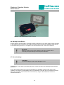
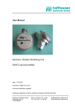
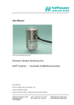
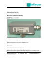
holthausen
elektronik GmbH
Instructions For Use
Electronic Vibration Monitor
ESW®-Mini-C (hol551)
The ESW Mini-C with a base plate
Read the instructions for use prior to using the device!
Date: 21.02.2011
Technical specifications subject to change without notice!
holthausen elektronik GmbH is certified in accordance with DIN EN ISO 9001.
®
ESW is a registered trademark of holthausen elektronik GmbH, Wevelinghoven 38, 41334 Nettetal, Germany
holthausen elektronik GmbH
Wevelinghoven 38
41334 Nettetal, Germany
Tel.: +49 (0) 21 53 - 40 08
Fax: +49 (0) 21 53 - 89 99 4
[email protected]
www.holthausen-elektronik.de
holthausen
Electronic Vibration Monitor
ESW®-Mini-C
elektronik GmbH
Table of Contents:
1 General Basic Safety Instructions .................................................................................3
1.1 Symbols Used in This Document ...................................................................4
2. Intended Use ................................................................................................................5
2.1. The Problem ...................................................................................................5
2.2. Application Area .............................................................................................5
2.3. Foreseeable Misuse .......................................................................................5
2.4. Special Features ............................................................................................5
3 Description of the Device ..............................................................................................6
3.1 Display and Operating Elements....................................................................6
4 Steps Involved for Use of the Device ............................................................................7
4.1 Identifying the Device .....................................................................................7
4.2 Packing, Dispatch and Storage ......................................................................7
4.3 Installing the Device .......................................................................................8
4.4 Connecting the Cable .....................................................................................9
4.5 Opening and Closing the Measurement Device ............................................9
4.6 Starting Up the Device .................................................................................10
4.7 Ground settings ............................................................................................10
4.8 Setting the Limit Level ..................................................................................11
4.9 Setting the measuring range ........................................................................11
4.10 Triggering the Self-Test Function .................................................................12
4.11 Troubleshooting in the Case of Faults .........................................................12
4.12 Normal Use of the Device ............................................................................13
4.13 Removal of the Device .................................................................................13
5. Method of Operation...................................................................................................14
6. Technical Data ...........................................................................................................16
6.1 Dimensions ...................................................................................................16
6.2 Drilling Template ..........................................................................................17
Specific Technical Data ................................................................................Appendix
Declaration of Conformity ............................................................................................18
2
holthausen
Electronic Vibration Monitor
ESW®-Mini-C
elektronik GmbH
Important Information
Prior to using the device, please read through this entire manual and follow the instructions contained
in it. The manufacturer accepts no liability for damage resulting from failure to observe or comply with
these instructions.
Tampering with the device or modifications to the device other than those described in this manual
will invalidate the warranty and the manufacturer's liability in respect of the device.
The device is exclusively designed for the purpose described below.
In particular, it is not intended for direct or indirect protection of persons.
holthausen elektronik GmbH provides no warranty of the device's suitability for other purposes.
If you have any questions, please contact us by telephone or in writing and we will be pleased to
assist you.
holthausen elektronik GmbH
Wevelinghoven 38
41334 Nettetal
Germany
Tel.: +49 (0) 21 53 - 40 08
Fax: +49 (0) 21 53 - 8 99 94
e-mail: [email protected]
1. General Basic Safety Instructions
Do not use this device as the sole monitoring device in situations where failure of the device can result
in damage to goods or personal injury.
The device complies with the requirements of Performance Level C as
specified in EN13849, and may not be used in locations or environments
requiring a higher performance level.
To achieve the desired results, make sure that the device and its technical data are suitable for use
with the device/equipment and parameters which you wish to monitor.
The location where the sensor is installed and the method used for installing the sensor have a
decisive impact on the quality of the sensor signal. The sensor may only be installed by appropriately
qualified and instructed staff.
Electrical connections must be made by appropriately skilled staff. Connection errors can lead to
malfunctioning or failure of, or irreparable damage to, the sensor and the electronics.
The connecting cable is resistant to many, but not all, chemicals. A defective cable can allow
chemicals to enter the housing and irreparably damage the electronics, in which case the device
would no longer work.
The conditions at the intended place of use must therefore be determined, and a check made as to
whether the cladding material can withstand these conditions. We will be pleased to provide you with
an overview of the chemical resistance of the cladding material.
3
holthausen
Electronic Vibration Monitor
ESW®-Mini-C
elektronik GmbH
1.1 Symbols Used in This Document
Safety Instructions
Safety instructions in this manual are identified by symbols. The
safety instructions are prefixed by attention-getting words which
indicate the level of danger involved.
Observe the safety instructions in all cases and proceed carefully in
order to avoid accidents, personal injury and damage to equipment
and property.
DANGER!
… indicates a definite hazardous situation which will result in death
or serious injuries if it is not avoided.
WARNING!
… indicates a possibly hazardous situation which can result in death
or serious injuries if it is not avoided.
CAUTION!
… indicates a possibly hazardous situation which can result in minor
or light injuries if it is not avoided.
CAUTION!
… indicates a possibly hazardous situation which can result in
damage to equipment or property if it is not avoided.
Tips and Recommendations
NOTE!
… draws your attention to useful tips, recommendations and
information for efficient and fault-free operation.
4
holthausen
Electronic Vibration Monitor
ESW®-Mini-C
elektronik GmbH
2. Intended Use
2.1. The Problem
Vibrations develop in many technical areas. Often they can be ignored or are even necessary, but
sometimes they are also undesirable or dangerous. Dangerous vibration states can also develop from
initially unnoticeable vibrations or completely unexpectedly.
The causes often lie in mechanical defects or unbalances or in improper use of the machine in
question. The consequences can include a deterioration of product quality, production losses and
safety hazards, and as a minimum increased wear.
Increased automation and, for example, high noise levels often hinder acoustic or visual monitoring.
Early detection, material treatment and protection and damage limitation offer a significant potential for
cost reductions.
2.2. Application Area
The device is used to protect machines, mechanical equipment and devices and last but not least the
operating staff against the impacts of excessively high vibration stress. It permanently monitors the
level of the vibration and provides a warning if the limit level is exceeded. The current level of the
vibration parameter can also be measured at any time via the analog output.
2.3. Foreseeable Misuse
WARNING!
• Never change the limit level to reduce assumed false alarms.
Clarify the cause of the alarms.
• Manipulation of the switch contacts of the alarm output or dismantling of
the device disable the monitoring function.
• Every modification or change can endanger safety.
2.4. Special Features
The device does not require special maintenance!
If you send the device to the manufacturer for inspection and checking, please enclose a detailed
description of the fault and provide the name of a contact person whom we can contact if we have
questions.
5
holthausen
Electronic Vibration Monitor
ESW®-Mini-C
elektronik GmbH
3. Description of the Device
3.1 Display and Operating Elements
The display and operating elements are accessed by opening the cover.
LED1
LED3
LED2
LED4
45
3
2
10
ST1
6
7
8
9
ON
12 34 5 6 7
Switch
Fig. 1: Display and operating elements
Display elements
LED1: The green Supply Voltage LED lights up as soon as the device is connected to the power
supply.
LED2: The green Self-Test LED lights up when the device is operating properly.
It stays off when a self-test is running.
LED3: The yellow Limit Level LED lights up if the currently measured level exceeds the set limit
level.
LED4: The red Alarm LED lights up when the alarm relay is in the "Alarm" position".
Operating elements
ST1:
The limit level switch is used to set the alarm threshold.
DIP-Switch:
S1
Connection shield-case
no Connection shield-case
ON
OFF
S2
Connection shield-internal ground
no Connection shield-internal ground
ON
OFF
S3
Selftest active
Selftest not active
ON
OFF
S4
no function
S5
no function
S6, S7 measuring range
15 mm/s
30 mm/s
45 mm/s
60 mm/s
S6
S7
OFF
ON
OFF
ON
OFF
OFF
ON
ON
6
holthausen
Electronic Vibration Monitor
ESW®-Mini-C
elektronik GmbH
4. Steps Involved for Use of the Device
4.1 Identifying the Device
WARNING!
Different device versions have different technical data.
The wrong device version can malfunction or fail during use.
Since the technical data are not directly visible on the device, you need to refer to the type label to
ensure that you have the right device for the task at hand.
First you need to determine what device version should be used.
You should then check the type label attached to the device.
In addition to the name of the manufacturer and the serial number, the type label also indicates the
device version.
If you are in any doubt, please contact the manufacturer to be on the safe side.
Meas. direction
Type Label
The type label is attached to the device and
includes the following information:
®
TYPE
: ESW -Mini-C
S/N
: xxyy - 123
holthausen
holthausen
elektronik GmbH
wevelinghoven 38
D-41334 nettetal
www.esw.eu
•
Type
•
Ser. No. xxyy - seq. no. (xx=week, yy=year)
•
Manufacturer
Fig. 2: Type label
4.2 Packing, Dispatch and Storage
CAUTION!
The device can become damaged if dropped onto a hard surface. The cable
can become damaged if it is bent or crushed.
The device must be sealed during transport and storage to protect it against dirt and moisture.
The connecting cable must be coiled with a minimum radius of 100mm and protected against
becoming kinked or crushed.
The bare ends of the conductors must be protected against unintentional contact with unknown
voltage levels.
During transport, the device must be suitably packed to protect it if it is dropped.
7
holthausen
Electronic Vibration Monitor
ESW®-Mini-C
elektronik GmbH
4.3 Installing the Device
Direction of vibration measurement
1
20
1 – Mounting surface
2 – Secure the M8
threaded pin with
Loctite.
A
2
0,03 A
Fig. 3: Installation drawing
In the version with a standard housing, the device is installed on the machine to be monitored using
two M4 threaded bolts. A drilling template is provided in Section 6.2. A sufficiently large, flat mounting
surface must be available around the mounting position for the device, perpendicular to the mounting
holes and the direction of vibration.
With the housing version with a base plate, the device is installed on the machine to be monitored
using a central M8 threaded pin. The maximum torque of 30 Nm may not be exceeded, and the force
may only be applied via the hexagonal element.
1. The measurement axis of the device must be aligned to the direction of vibration
(see the drawing of the housing).
2. The instructions on the device must be complied with in all cases.
3. The mounting surface must be flat, clean and free of paint and rust.
4. The threaded hole(s) must be perpendicular to the mounting surface and free of swarf and other
foreign bodies. The threaded hole(s) may also not contain any paint, rust, lubricant or insulation
material. This also applies to the threaded hole in the device and to the threaded pin.
5. The threaded pin and the mounting bolts must be secured using a suitable liquid fixing agent to
prevent unintentional loosening.
6. The device must be lie solidly on the mounting surface.
CAUTION!
When the device has been installed, the connecting cable is laid. Care must
be taken that the cable is on the one hand fitted sufficiently flexibly, to ensure
that it does not become torn off during excessive vibration. On the other hand
it must be laid sufficiently firmly to ensure that it can not itself generate noises
due to impacts, that it is protected against damage during normal operation,
and that it does not create a risk of accidents due to tripping or stumbling over
it. The bend radius of the connecting cable may in no case be less than 70
mm.
8
holthausen
Electronic Vibration Monitor
ESW®-Mini-C
elektronik GmbH
4.4 Connecting the Cable
Once the cable has been properly laid, the individual wires must be connected in accordance with the
wiring diagram (see the data sheet).
CAUTION!
Check the supply voltage and switch it off when fitting and connecting the
device.
4.5 Opening and Closing the Measurement Device
Figure 4: The device viewed from above
• To open the measurement device, the user requires a Size 2 Phillips screwdriver or a flathead screwdriver with a head width of approx. 6 mm.
• After adjusting the unit the position of the DIP-Switch has to be checked.
• Prior to fitting the cover the seal must be inspected. If it is brittle, deformed or damaged the
device can no longer fulfil the requirements of the specified IP protection class.
• It must be ensured that the threads and the interior are free from dirt and oil. The outside and
inside of the device may only be cleaned using a clean, dry cloth.
9
holthausen
Electronic Vibration Monitor
ESW®-Mini-C
elektronik GmbH
Figure 5: The device with the cover removed
4.6 Starting Up the Device
First the settings must be made in accordance with the instructions. The power supply is then switched
on and a start-up test is executed. The LEDs, the analog output and the relay switching states should
be monitored during the test. On completion of the test the device the cover is then replaced.
CAUTION!
Switching actions on the relay contacts in the start-up phase can be
incorrectly interpreted during the subsequent evaluation.
4.7 Ground settings
CAUTION!
Excessice leakage current could damage the unit.
If interference occurs and the grounding may be the cause in question, the following steps should be
performed.
First of all separate masses and control level between the individual masses under various load
conditions. If necessary, experimentally test the unit isolated. Locate the case of excessive levels and
elimninate, if possible. Test several mass connections by using the DIP switches S1 and S2 to
minimize interference.
10
holthausen
Electronic Vibration Monitor
ESW®-Mini-C
elektronik GmbH
Finally switch S1 and S2 into the desired position and close the device.
Check secure attachment of device and cable.
S1
Connection shield - case
no Connection shield - case
ON
OFF
S2
Connection shield - internal ground
no Connection shield - internal ground
ON
OFF
4.8 Setting the Limit Level
WARNING!
The correct limit level depends on the measurement task and may not be
changed without careful consideration of the impacts.
If a large number of alarms are generated, the reason for these should first be
established rather than simply changing the limit level.
• To change the limit level, the device must first be opened.
• The desired limit level is then set using the limit level step switch. The step switch is marked with
the numbers 0 to 9. Switch position 1 corresponds to a limit level of 10%, position 6 corresponds to a
limit level of 60%, and position 0 corresponds to a limit level of 100% of the measurement range.
The switch does not have an end stop and can be rotated through 360° without a risk of damage.
• Having set the limit level, the device is then closed again.
LED1
LED3
LED2
ST1
LED4
45
3
2
10
6
7
8
9
ST1
1 ≙ 10%
2 ≙ 20%
.
.
ON
9 ≙ 90%
12 34 5 6 7
0 ≙ 100%
Switch
Figure. 6: Interior view
4.9 Setting the measuring range
The device has the possibility to adjust the measuring range.
WARNING!
Setting the measuring range can not be changed carelessly.
When alarms pile first looking for the reason and suppress them.
11
holthausen
Electronic Vibration Monitor
ESW®-Mini-C
elektronik GmbH
• To adjust the measuring range first open the unit.
• The measuring range is adjusted as specified with the DIP-Switch S6 and S7.
• Then the device will be closed.
measuring range
switch position
S6
S7
15mm/s
OFF
OFF
30mm/s
ON
OFF
45mm/s
OFF
ON
60mm/s
ON
ON
4.10 Triggering the Self-Test Function
A) Triggering the start-up test
Switch the device off and then on again.
The device carries out a start-up test and then operates normally.
The scope of the test is defined in the factory.
B) Automatic self-test
open device
if S3 = OFF => DIP-switch S3 switch ON and OFF
if S3 = ON => DIP-switch S3 switch OFF and ON
close device
The device carries out a self-test and then operates normally.
The scope of the test is defined in the factory.
C) Self-test trigger with ext. switch
trigger ext. switch for self-test (control wire to +24V)
The device carries out a self-test and then operates normally.
The scope of the test is defined in the factory.
D) Automatic selft-test switch on and off
open device
S3 is ON: automatic self-test is active
S3 is OFF: automatic self-test is not active
close device
The unit performs a self-test, apply the settings and then operates normally.
The scope of the test is defined in the factory.
4.11 Troubleshooting in the Case of Faults
If the device reacts other than expected right from the start, first check the device version and the
associated factory settings.
If the device suddenly indicates disproportionately high or low values, the operating conditions of the
machine, the machine itself and the mounting of the device should be checked. Loose components,
rattling, background noises etc. can result in incorrect indications.
12
holthausen
Electronic Vibration Monitor
ESW®-Mini-C
elektronik GmbH
Fault:
The alarm relay permanently indicates an alarm, the analog
output current is 0 mA
Visible reaction:
All LEDs remain unlit
Possible reasons:
No power supply
Cable connected incorrectly
Fault:
The alarm relay permanently indicates an alarm, the analog
output current is 22 mA
Visible reaction:
The Test OK LED remains unlit
The limit level LED is lit
The alarm contact LED is lit
Possible reasons:
Incorrect supply voltage
Analog output open or incorrectly connected
Fault:
The analog output current does not match the expected
current level.
The alarm relay activates too soon or too late
Visible reaction:
None, everything appears normal
Possible reasons:
Device mounted incorrectly, is loose, rattles
Interfering noise source
Wrong limit level set
Make sure that the device is mounted securely
Set the correct limit level
Possible remedy:
Fault:
Analog output current 0 mA or > 22 mA
Visible reaction:
None, everything appears normal
Possible reasons:
Incorrect wiring connections
Incorrect load impedance
Possible remedy:
Measure directly on the device
Check the wiring
4.12 Normal Use of the Device
During normal use the level of the analog output can be monitored to determine whether and to what
extent the level of vibration changes depending on the use of the machine.
If the indicated vibration level changes abruptly, the reason for this should be determined.
NOTE!
To ensure the functional reliability the self-test function should be constantly
usedt. The frequency depends on the use of the unit and the operational
circumstances e.g. every 100 operating hours or mounthly.
Correct seating and proper condition of the device should be checked on a regular basis.
13
holthausen
Electronic Vibration Monitor
ESW®-Mini-C
elektronik GmbH
4.13 Removal of the Device
CAUTION!
To avoid short-circuits and false alarms, make sure that the power supply and
the signal evaluation are switched off and/or disconnected.
To electrically disconnect the device from the machine and physically remove it from the machine, the
power must first be disconnected from all connections to prevent short-circuits. The downstream
evaluation is then to be prepared for the disconnection, to avoid false alarms. The cable connections
can then be disconnected from the device.
The cable glands and clamps are then dismantled and the cable removed up to the device. The device
can now be unscrewed and removed together with the cable.
All loose and sharp-edged parts are then re-secured or removed.
The mounting holes for the device must be protected using suitable sealing plugs.
The removal of the device must be indicated on the machine.
5. Method of Operation
S6
Bandpass
Limit value
setting
LEDs
- Power Supply
- Test ok
- Limit level
- Alarm-Co ntact
Integrator
Comperator
S7
Measuring
ra nge switch
Mean value
Alarm-Rela y
1A, 30V
ok-Relay
1A, 30V
S3
Self-Test
ext. Self-Test
Powersup ply
Circuitground
S2
20mA
GND
Analo gground
Closer
Switchingtime
Contr oller
Ana logoutput
4 to 20mA
S1
= Supplyground
Shi eld
Sensor
for mech. Vibration
Casegrou nd
= Machineground
Figure 7: Functional diagram
14
Opener
Centercontact
holthausen
Electronic Vibration Monitor
ESW®-Mini-C
elektronik GmbH
Sensor
The task of the sensor is to register mechanical vibrations at the location where the device is installed
and to convert these vibrations into electrical signals. It only registers vibration components in its
primary vibration direction. The primary vibration direction is indicated on the outside of the housing.
Bandpass filter
The bandpass filter filters the relevant signal components from the registered composite signal and
suppresses interference signals.
Integrator
The integrator converts the sensor signal into a vibration speed signal, since the speed of vibration is
proportional to the energy of the vibrations.
Measuring range
The measuring range determines the sensitivity of the device. Depending on the version he is fixed or
can be adjusted with the switch S6 and S7 inside the case.
LEDs
The LED indicators provide information on the current device status.
The green "Power Supply" LED lights up when power is applied to the device.
During the start-up test when the device is switched on, and during subsequent tests, the green "Test
OK" LED initially blinks and then lights up permanently if no faults are found during the tests. If a fault
is detected during the test, the LED does not light up.
The yellow "Limit Level" LED lights up as soon as the measured value exceeds the limit value.
The red "Alarm Contact" LED lights up as soon as and as long as the alarm relay has activated, and
at the same time the "Test OK" LED goes out.
Limit level setting
The task of the device is to monitor the measured level and to permanently compare it with a set limit
level, to enable activation of the alarm relay if the limit level is exceeded.
The limit level can be set using a step switch in the device.
The limit level can be set in 10% steps in a range from 10% to 100% of the measurement range.
Signal processing
In the signal processing module the measured signal is first rectified and averaged.
This average or mean value is on the one hand output again as an analog value, and is also
compared with the limit level. If the measured value exceeds the limit level, an alarm is output
following the activation delay. If the measured value subsequently falls below the limit level again, the
alarm is cancelled following the fall delay. The alarm output controls the alarm relay.
Self-test function
To ensure operational reliability, various function tests are executed.
Each time the device is switched on a start-up test is first executed.
Additional functional tests which run in the background are also executed at regular intervals.
Analog output
The analog output provides a constant current corresponding to the mean level of the measurement
signal. The analog output is extremely immune to interference and can be transmitted over long
distances (several 100 m) using a twisted wire pair.
The load impedance can be between 0 and 500 Ohm.
15
holthausen
Electronic Vibration Monitor
ESW®-Mini-C
elektronik GmbH
Switching output
The device has an alarm relay and an OK relay. The contacts are wired in series.
During normal operation the alarm relay is closed; it drops out in the case of an alarm when the limit
value is exceeded or a fault is detected.
On request, a test function can be incorporated in the factory with which the relay switches twice to
check the functionality of the relay.
The OK relay is closed during normal operation, and drops out when faults are detected. On request, a
test function can be incorporated in the factory with which the relay switches once to check the
functionality of the relay.
6. Technical Data
6.1 Dimensions
34
98
64
“1”
4
20
“2”
1: Direction of vibration measurement
2: max. 11 mm usable thread depth (M10)
M8
SW19
The device is fixed in place using an M8
threaded pin (qty. 1).
Figure. 9: Dimensions
16
holthausen
Electronic Vibration Monitor
ESW®-Mini-C
elektronik GmbH
6.2 Drilling Template
86
36
The device is fixed in place
using M4 threaded bolts (qty. 2)
Fig 10: Standard housing
The device is fixed in place
using an M8 thread pin (qty. 1)
Fig. 11: Housing with a base plate and fixing bolts
17
holthausen
Electronic Vibration Monitor
ESW®-Mini-C
elektronik GmbH
EC Declaration of Conformity
within the context of EC Directive 2004/108/EC
and the Machinery Directive 2006/42/EC
We herewith declare that the design and construction of the:
vibration monitor for monitoring vibrations
ESW®-Mini-C
complies with the following standards:
EN 61000 - 6 - 4
Emission standard for industrial environments
EN 61000 - 6 - 2
Immunity for industrial environments
EN 61010 - 1
Safety requirements for electrical equipment for
measurement, control, and laboratory use
EN 13849 - 2
Safety of Machinery
Manufacturer
holthausen elektronik GmbH
Registered office
Wevelinghoven 38
41334 Nettetal
Germany
Managing Director
Michael Holthausen
Town
Date
Nettetal
27.11.2010
Signature
_______________________
18