1
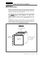
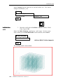
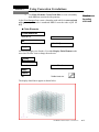
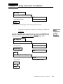
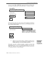
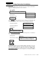
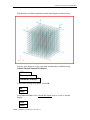
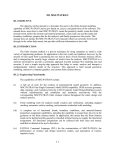
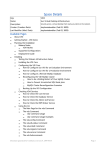
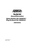
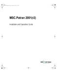
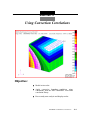
Exercise 11
Using Convection Correlations
Objective:
■
Model an iron cube.
■
Apply convective boundary conditions using
correlations from the MSC/THERMAL convection
correlation library.
■
Run a steady state analysis and display results.
PATRAN 312 Exercises -Version 7.5
11-1
11-2
PATRAN 312 Exercises -Version 7.5
Exercise 11
Using Convection Correlations
Model Description:
In this exercise you will determine the steady state temperature distribution
in an iron cube (MID 18). The temperature distribution will be driven by a
heat flux on one vertical face, natural convection on another vertical face,
and forced convection on the top horizontal face.
CONV definitions link convection Template ID’s (TID’s) which are applied
in the Loads/BC’s form to convection configurations and associated Material
Property ID’s (MPID’s). CONV definitions are edited into a
template.dat.apnd file which you create in the same directory as your
database. MPID’s for air will be placed in a mat.dat.apnd which you also
create.
MSC/PATRAN contains an extensive library of convection coefficient
configurations. The configurations are described in Chapter 9, Volume 1 of
the MSC/THERMAL Application Module User Manual. This volume can
be accessed through the on-line Help/Document Library...
Figure 1
Forced Convection
T = 300oK
V = 10 m/s
Heat flux
1000 W/m2
Iron Cube
(MID =18)
Natural convection
Tamb = 300oK
g = 9.81 m/s2
PATRAN 312 Exercises - Version 7.5
11-3
Exercise Overview:
11-4
■
Create a new database named exercise_11.db. Set Tolerance to
Default, and the Analysis Code to MSC/THERMAL.
■
Create a 1m x 1m x 1m solid.
■
Mesh the solid with an IsoMesh of Hex8 elements, Global
Edge Length of 0.100.
■
Use Finite Elements/Create/Node/Edit to create a boundary
node not associated with geometry.
■
Apply element properties to the Hex8 elements defining them
as Thermal 3D Solid and having a Material Name (MID) of
18.
■
Create a spatial field which will provide distance-from-theleading-edge data to the convection coefficient calculation.
■
Define a fixed temperature and heat flux boundary condition in
Loads/BCs.
■
Define two convection boundary conditions assigning each a
different Convection Template ID and supplying the distance
from the leading edge in the Convection Coefficient data box.
■
Open a new window (shell) and in the directory which contains
the database edit a file named template.dat.apnd creating the
CONV definitions.
■
In your xterm window (shell) and in the directory which
contains the database, copy an existing file, <P3_HOME>/
p3thermal_files/examples/qtran/prob4/mat.dat.apnd,
containing air MPID data to your directory.
■
Prepare and submit the model for analysis specifying that it is
a steady state, that all calculations and output should be oK, and
that all eight columns of nodal results are included in the nodal
results file.
■
Read and plot the results.
■
Quit MSC/PATRAN.
PATRAN 312 Exercises -Version 7.5
Using Convection Correlations
Exercise 11
Exercise Procedure:
1.
Open a new database named exercise_11.db.
Within your window environment change directories to a convenient
working directory. Run MSC/PATRAN by typing p3 in your xterm window.
Open a new
database
Next, select File from the Menu Bar and select New… from the drop-down
menu. Assign the name exercise_11.db to the new database by clicking in
the New Database Name box and entering exercise_11
Select OK to create the new database
File
New
New Database Name
exercise_11
OK
MSC/PATRAN will open a Viewport and change various Main Form
selections from a ghosted appearance to a bold format. When the New Model
Preferences form appears on your screen, set the Tolerance to Default, and
the Analysis Code to MSC/THERMAL. Select OK to close the New Model
Preferences form.
Tolerance
◆ Default
Analysis Code
MSC/THERMAL
OK
2.
Create a 1m x 1m x 1m solid.
Select the Geometry Applications radio button. Create a solid using the
following Action, Object, and Method.
Create solid
geometry
◆ Geometry
Create/Solid/XYZ
Vector Coordinate List
<1 1 1 >
Apply
PATRAN 312 Exercises - Version 7.5
11-5
IsoMesh the solid
Select Viewing from the Menu Bar or use the ToolBar Iso 1 View icon to
change to an isometric_view.
Viewing
Named View Options...
Select Named View
isometric_view
Close
or,
IsoMesh the
solid
3.
Mesh the solid with an IsoMesh of Hex8 elements, Global
Edge Length of 0.1.
Select the Finite Elements Applications radio button. Set the Action,
Object, and Type to Create/Mesh/Solid. For the solid list, select Solid 1.
◆ Finite Elements
Create/Mesh/Solid
Solid List
Apply
The resulting model is shown below.
11-6
PATRAN 312 Exercises -Version 7.5
<click on Solid 1 in the viewport>
Using Convection Correlations
Exercise 11
4.
Use Finite Elements Create/Node/Edit to create a boundary
node 9999 not associated with geometry.
In the Finite Elements form create a boundary node which is not associated
with geometry. The node is numbered 9999. Locate the node at [1.3 1.3
0.5].
Create a
boundary
sink node
◆ Finite Elements
Create/Node/Edit
Node ID List
9999
Associate with Geometry
Node Location List
[1.3 1.3 0.5]
Apply
Increase the display size of nodes. Use either Display Finite Element or the
associated ToolBar icon to change the node size.
Display
Finite Element
Node Size
6 <use slider bar>
Apply
Cancel
or,
ToolBar Node size
The display should now appear as shown below.
PATRAN 312 Exercises - Version 7.5
11-7
Apply element properties
5.
Apply
element
properties
Apply element properties to the Hex8’s defining them as
Thermal 3D Solid and having a material name (MID) of 18.
Select the Properties Applications radio button. Set the Action, Dimension,
and Type to Create/3D/Thermal 3D Solid. Enter Property Set Name
Prop1. Select the Input Properties... box. Click in the Material Name box
and enter 18. Select OK to close the form.Click in the Select Members box
and select Solid 1 in the viewport. Select Add then Apply in the Element
Properties form to complete the element property definition.
◆ Properties
Create/3D/Thermal 3D Solid
Property Set Name
Prop1
Input Properties...
Material Name
18
Ok
Select Members
<select Solid 1 in the viewport>
Add
Apply
6.
Create a spatial field which will provide distance-from-theleading-edge data to the convection coefficient calculation.
In the forced convection boundary conditions the heat transfer coefficient
varies as the thermal boundary layer develops from a leading edge. One
input to the convective correlation is the distance from the leading edge of
the surface. MSC/THERMAL provides for spatial fields to define the
element distance from the leading edge. You will create a spatially varying
field that will define the required distance.
Click on the Fields toggle. Set the Action, Object, and Method to Create/
Spatial/PCL Function. Enter, X_dist, in the Field Name box. Next, click
in the Scalar Function text box and select ’X from Independent Variable list
box. Since the global coordinate system’s origin is located at a lower left
corner of the Solid the simple function, f(x)=x, represents the horizontal
distance from the leading edge of the top surface where the forced
convection heat transfer will occur. Click on Apply to create the field.
The natural convection coefficient calculation uses the characteristic length
L of the vertical side. This will be input in the template.dat.apnd file GP
list which will be described later in the exercise.
11-8
PATRAN 312 Exercises -Version 7.5
Using Convection Correlations
Exercise 11
◆ Fields
Create/Spatial/PCL Function
Field Name
X_dist
Independent Variable
’X
Apply
The field name should appear in the Existing Fields list box.
7.
Create fixed temperature and heat flux boundary condition in
Loads/BC’s.
Select the Load/BCs Applications radio button. Create a fixed 300oK nodal
boundary temperature named Tamb. In the Input Data form define the fixed
temperature. In the Select Application Region form pick Node 9999.
Apply
temperature
and flux
boundary
conditions
◆ Load/BCs
Create/Temperature/Nodal
Option:
Fixed
New Set Name
Tamb
Input Data...
Fixed Temperature
300.0
OK
Select Application Region...
Geometry Filter
◆ FEM
Select Nodes
<select Node 9999>
Add
OK
Apply
PATRAN 312 Exercises - Version 7.5
11-9
Create two convection Template ID’s
Create a set name Flux of 1000 W/m2. Apply the boundary condition to the
left facing (-X normal) surface of the solid, Solid 1.1, as shown in Figure1.
◆ Load/BCs
Create/Heating/Element Uniform
Option:
Fluxes
New Set Name
Flux
Target Element Type
3D
Input Data...
Heat Flux
1000
OK
When selecting a surface, the surface chosen will be highlighted. Hold down
the <Shift> key and use the right mouse button to cycle through surfaces that
may overlap or share an edge.
Select Application Region...
Geometry Filter
◆Geometry
Select Solid Faces
<select (-X normal) face of Solid 1,
(Solid 1.1), use shift-right mouse
button to cycle pick, if necessary>
Add
OK
Apply
8.
Define two convection boundary conditions assigning each a
different Template ID and supplying the distance from the
leading edge in the Convection Coefficient data box.
Create the convection coefficient boundary conditions with the Use
Correlations option, New Set Name forced_convection, with a fluid node
9999, and a Template ID of 93. Apply the boundary condition to the top face
(+Y normal) of Solid 1 as shown in Figure1.
11-10
PATRAN 312 Exercises -Version 7.5
Create two
convection
Template ID’s
Exercise 11
Using Convection Correlations
Spatial field X_dist will be used in the Convection Coefficient data field to
supply the leading edge distance to the correlation.
◆ Load/BCs
Create/Convection/Element Uniform
Option:
Use Correlations
New Set Name
forced_convection
Target Element Type
3D
Input Data...
In the Input Data form provide the Convection Template ID, fluid node, and
Geometric Properties 2 and 3 via the Convection Coefficient data box.
Convection Coefficient
<select X_dist from the
Spatial Fields list box>
Convection Template ID
93
Fluid Node ID
9999
OK
Select Application Region...
In the Select Applications Region form select the top face (+Y normal) of
Solid 1.
Geometry Filter
◆Geometry
Select Surfaces or Edges
<select the top face (+Y normal) of Solid
1, (Solid 1.4), as shown in Figure 1>
Add
OK
Apply
Repeat these steps for a New Set Name natural_convection. Click in the
Convection Coefficient data box. Leave the Convection Coefficient blank.
Use a Convection Template ID of 913, and a Fluid Node of 9999. In the
Select Applications Region form select the right face (+X normal) of Solid 1,
(Solid 1.2).
PATRAN 312 Exercises - Version 7.5
11-11
Create two convection Template ID’s
With boundary conditions applied the model should appear as shown below
You may also choose to review your loads and boundary conditions using
Utilities/Thermal/Thermal BCs Display.
Utilities
Thermal
Thermal BC Display...
A disclaimer message may appear, select OK..
OK
Apply
Use Clear and Close in the Thermal BC Display form to revert to normal
display.
Clear
Close
11-12
PATRAN 312 Exercises -Version 7.5
Using Convection Correlations
Exercise 11
9.
Open a new window (shell) and in the directory which contains
the database edit a file named template.dat.apnd creating the
CONV definitions.
Open a unix xterm window and change directories (cd) to the directory
which contains your database.
In unix create
template.dat.
apnd file
If a template.dat.apnd already exists in this directory rename it to associate
it with that previous analysis. For instance, in Exercise 10 you created a
template.dat.apnd file. Use the following unix command to move it to a
new name associated with that analysis:
> mv template.dat.apnd 10_template.dat.apnd
Using the system editor, create and edit the file template.dat.apnd in the
directory which contains your database and where MSC/PATRAN is
running.
Following is a detailed description of what you will be entering into the file.
The actual entries are fairly brief and listed following the detailed
description of the complete syntax.
Create two convection templates, one for the forced_convection and the
other for the natural_convection boundary condition. The format for the
CONV functions are as follows:
CONV TID# config# number_of_GP_values number_of_MPID_values
gp#2
gp#3
… gp#n
mpid#1
mpid#2
… mpid#n
Where, TID:
The template ID number (pointer) you entered in the Load/BCs form.
config#:
Convection type configuration number.
Identifies the type of convection class (e.g. 1=forced convection, smooth
Isothermal tubes, 3=flat plate, forced convection, etc.).
number_of_GP_values:
Number of general properties needed for a specific convection
configuration.
Example: For config=3 (forced convection over a horizontal surface)
GP(1) = element surface area (automatically supplied by MSC/PATRAN)
GP(2) = shortest distance form plate’s leading edge to element.
GP(3) = longest distance from plate’s leading edge to element.
GP(4) = free stream velocity
PATRAN 312 Exercises - Version 7.5
11-13
In unix copy a mat.dat.apnd file
number_of_MPID_values:
Number of Material Property ID numbers used to point to material
properties.
Example: For config = 3 (mpid#’s point to)
MPID(1) = fluid density, ρ
MPID(2) = fluid dynamic viscosity, µ
MPID(3) = fluid specific heat, Cp
MPID(4) = fluid thermal conductivity, κ
Note: CONV is a keyword and must be typed in uppercase.
Use the following table to help you define the convection templates for the
forced and natural convection boundary conditions. You should also review
the definition of the convection configuration 3 and 13 in the
MSC⁄THERMAL USERS MANUAL, Volume 1, Chapter 9.
Conv
Type
TID#
config#
#GP
#MPID
Forced
93
3
1
4
550100, 550101, 550103, 550105
Natural
913
13
4
5
550100, 550101, 550106, 550103, 550105
MPID’s (order is important)
Shown below is the final form of the template.dat.apnd file created for this
exercise. Note that any comment lines must be started with an * in column
1 and make sure that there are no blank lines especially at the end of the file.
Start typing from the first column and do no enter any blank lines.
*==================================
CONV 93 3 1 4
10.0
550100 550101 550103 550105
CONV 913 13 4 5
1.0 1.0 0.0 9.8
550100 550101 550106 550103 550105
*==================================
In unix copy a
mat.dat.apnd
file
10. In your xterm window (shell) and in the directory which
contains the database, copy an existing file, <path>/
p3thermal_files/examples/qtran/prob4/mat.dat.apnd,
containing air MPID data to your directory.
Copy a mat.dat.apnd file into the same directory in which you’ve created
the template.dat.apnd file. The commands are as follows:
> which p3
11-14
PATRAN 312 Exercises -Version 7.5
Using Convection Correlations
Exercise 11
(response) > <path>/bin/p3
> cp <path>/p3thermal_files/examples/qtran/prob4/mat.dat.apnd .
A mat.dat.apnd should now reside in your database subdirectory. This file
contains more material properties than required. This will not adversely
affect the analysis. Feel free to review the format and syntax of the
mat.dat.apnd file. You can use this file as a boiler plate for creating your own
material properties file data.
The template.dat.apnd and mat.dat.apnd files are the only two files that
may need to be created outside of the MSC/PATRAN in order to complete
an analysis. As MSC/PATRAN evolves the creation of this files will be
absorbed within the MSC/PATRAN interface.
11. Prepare and submit the model for analysis.
Select the Analysis Applications radio button to prepare the analysis. Select
the parameter forms reviewing and changing the settings as shown below.
The analysis is submitted by selecting Apply in the Analysis form.
Prepare and
run analysis
◆ Analysis
Analyze/Full Model/Full Run
Translation Parameters...
OK
Solution Parameters...
Run Control Parameters...
Initial Temperature Scale
◆ Kelvin
Initial Temperature =
300.0
OK
OK
Output Requests...
Units Scale for Output Temperatures
◆ Kelvin
Nodal Results File Format...
Select Thermal Entries to Output
<select all 8 items listed>
OK
Diagnostic Output
◆ Convection Resistors
OK
PATRAN 312 Exercises - Version 7.5
11-15
Read and plot results
OK
Apply
Read and plot
results
12. Read and plot the results.
From within MCS/PATRAN the only indication that the analysis has
successfully finished is the existence of an nr0.nrf.01 results file in a
subdirectory one level below your working directory.
P3 was initiated from a working directory which contained the
exercise_11.db database. Applying the analysis created a new subdirectory
with the same name as the Job Name, exercise_11/. By using Read Result
in the Analysis form and Select Results File... you can filter down to the Job
Name subdirectory and check for the existence of a results file.
◆ Analysis
Read Results/Result Entities
Select Results File...
Directories
<path>/exercise_11
Filter
Available Files
nr0.nrf.01
OK
Select Rslt Template File...
Files
pthermal_nod_T.res_tmpl
OK
Apply
There may be a warning message regarding Qmacro, select OK.
OK
Reduce the node size using Node Size icon.
11-16
PATRAN 312 Exercises -Version 7.5
Exercise 11
Using Convection Correlations
After results are read in plot the results. To plot the results use the Results
Application radio button. Select you results file.
◆ Results
Create/Quick Plot
Select Result Cases
TIME: 0.0000000000D+00 S...
Select Fringe Result
Temperature,
Select the Fringe Attributes icon.
Display:
Element Edges
Label Style...
Label Format:
Fixed
Significant figures
4 <use slider bar>
OK
Apply
The model should now appear as shown on the front panel of this exercise.
Feel free to plot the value of the heat transfer coefficient (and other
quantities) using Select Fringe Result.
To plot the heat transfer coefficient data:
◆ Results
Form Type:
Basic
Select Result Case
2.1-Time: 0.0000000000D
Select Fringe Results
6.1-Average Convection Coefficient
Apply
The nodal averaged h’s are displayed in the viewport.
To view detailed convection resistor data look in qout.dat.01 file in the Job
Name subdirectory. Search for string “CONVECTIVE RESISTOR DATA.”
PATRAN 312 Exercises - Version 7.5
11-17
Quit MSC/Patran
13. Quit MSC/PATRAN
Quit MSC/
Patran
To stop MSC/PATRAN select File on the Menu Bar and select Quit from
the drop-down menu.
11-18
PATRAN 312 Exercises -Version 7.5