1
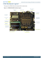
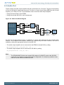
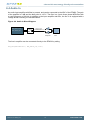
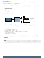
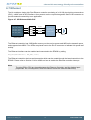
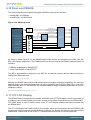
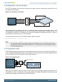
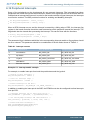
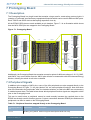
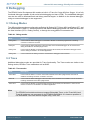
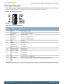
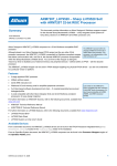
...the world's most energy friendly microcontrollers
USER MANUAL
Development Kit EFM32G-DK3550
The EFM32 Gecko Development Kit is a feature rich development platform for
evaluation,prototyping and application development for the EFM32 Gecko MCU
family with the ARM Cortex-M4 CPU core.
Main features:
• Advanced Energy Monitoring provides real-time information about the energy
consumption of an application or prototype design.
• Integrated emulator providing full debug and trace capability
• Exchangeable prototyping board for custom application circuit development
...the world's most energy friendly microcontrollers
1 Introduction
1.1 Description
The EFM32G-DK3550 is a highly flexible development platform demonstrating some of the EFM32
Gecko microcontroller's many capabilities. The rich feature set makes the kit an excellent platform for
evaluating the microcontroller as well as a good starting point for application development.
The EFM32G-DK3550 kit consists of three separate boards:
• 1 x BRD3201A EFM32 Development Kit Motherboard
• 1 x BRD3302A EFM32 G890 MCU plugin board
• 1 x BRD3500B EXP32 prototyping board
The EFM32 G890 MCU is mounted on the plugin board, which plugs into the Motherboard. All the EFM32
GPIO pins are available through pin headers on the prototyping board.
Additional kit contents:
• IAR Embedded Workbench ARM Kickstart version CD/DVD
• Atollic TrueSTUDIO for ARM evaluation CD
• USB cables
1.2 Features
•
•
•
•
•
•
•
•
•
•
•
•
•
•
•
•
•
•
•
Advanced Energy Monitoring system for precise current tracking.
Special hardware configuration for isolation of the MCU power domain.
Replaceable prototyping board for quick custom application development.
Full feature USB debugger / emulator with trace support and debug out functionality.
3.5-inch TFT-LCD 320x240 pixel RGB color display with resistive touch film.
Smart Board Controller handles configuration and signal routing.
Single ended and differential ADC inputs.
Line-in stereo audio input amplifier.
Line-out stereo audio output amplifier.
1 x RS232 Serial Port (DSUB-9).
10/100 Mbps Ethernet MAC+PHY with SPI interface
MicroSD card reader (SPI mode).
2Meg x 16 (4MB) PSRAM with 70ns access time.
8Meg x 16 (16MB) NOR Flash with 90ns access time.
2Kb I2C EEPROM.
Temperature sensor with I2C interface.
5 way joystick.
4 User buttons, 4-bit DIP switch and 16 user LEDs.
4x40 Segment LCD
2013-10-10 - t0023_0.31
2
www.silabs.com
...the world's most energy friendly microcontrollers
2 Kit Block Diagram
An overview of the EFM32 Gecko Development Kit is shown in Figure 2.1
Figure 2.1. EFM32G-DK3550 Block Diagram
2013-10-10 - t0023_0.31
3
www.silabs.com
...the world's most energy friendly microcontrollers
3 Kit Hardware Layout
The layout of the EFM32 Gecko Development Kit is shown below.
Figure 3.1. EFM32G-DK3550 hardware layout
MCU Plugin
Board
RS232 UART &
LEUART
Power & USB
10/ 100Mbps
Ethernet
J- Link Debug
Connector
Single Ended &
Differential
Analog Inputs
4x 40 Segm ent
LCD
16 MB NOR- Flash
4MB PSRAM
Analog Audio
Input/ Output
MicroSD
Card Slot
320x 240 LCD
TFT Display w/
resistive touch
Power Button
Buttons & Joystick
User LEDs
2013-10-10 - t0023_0.31
4
www.silabs.com
...the world's most energy friendly microcontrollers
4 Using the EFM32G-DK3550
The EFM32 Gecko Development Kit is intended to be a complete platform for developing applications
for the EFM32 microcontroller. The embedded debugger allows applications to be downloaded and
debugged directly. A set of useful peripherals is provided, and custom hardware can be developed on
the prototyping area, where all the microcontroller's IO pins are made available.
By default the peripherals on the board are not connected to the MCU. Interfacing the peripherals is
done entirely without using jumpers, but instead through the kit's board controller. Two main approaches
exist to configuring the board for an application: from within the application itself using the Board Support
Packge, or by using the kit's user interface.
4.1 Board Support Package
The kit Board Support Package, or BSP, is provided to allow an application to control various aspects
of the EFM32G-DK3550 kit. Peripherals can be connected or disconnected with simple calls to the API.
The user buttons and LEDs are also accessed through the BSP.
The easiest way to obtain the latest version of the BSP is through Simplicity Studio. It can also be
downloaded at: http://www.energymicro.com/downloads/software.
The BSP can be configured to use two different methods of communication toward the board controller:
SPI mode or EBI mode. In SPI mode the EFM32 communicates with the board controller using a simple
4-wire SPI bus, and in EBI mode the board controller becomes a memory-mapped peripheral in the
EFM32's address space using the EFM32's External Bus Interface module.
SPI mode uses fewer pins to communicate with the board controller, but the external memory devices
and TFT-display are not available in this mode. Use this mode when the IO taken up by the EBI are
needed for other purposes. To enable the board controller in SPI-mode use the BSP function from within
the application code:
BSP_Init ( BSP_INIT_DK_SPI )
EBI mode is the preferred mode of interfacing to the board controller. This gives access to all the board
functions as well as the external memory devices (PSRAM and Flash) and the TFT-LCD display. To
enable the board controller in EBI-mode use the BSP function from within the application code:
BSP_Init ( BSP_INIT_DK_EBI )
In order to configure the BSP, some dedicated GPIO pins are used. These pins are listed in Table 4.1,
and are normally controlled by the BSP. No manual configuration of these pins are necessary.
Table 4.1. GPIO's used for BSP functions
MCU Pin
Description
PB15
Board controller configuration line 1.
PD13
Board controller configuration line 2.
PE2
Interrupt request from board controller.
Once the BSP has been configured, the different peripherals and kit functions can be accessed through
the BSP API. Please refer to Chapter 6 for detailed information about the different kit peripherals and
how to access them with the BSP. It can also be useful to take a look at some of the software examples
found in Simplicity Studio.
Note
Full documentation and source code for the BSP can be found in Simplicity Studio.
2013-10-10 - t0023_0.31
5
www.silabs.com
...the world's most energy friendly microcontrollers
4.2 User Interface
In addition to using the API provided by the BSP, the kit can also be configured through the graphical
user interface consisting of the TFT-LCD display together with the buttons PB1 to PB4 and the 5-way
joystick located below. The board controller provides a simple menu system, allowing most aspects of
the kit to be configured directly.
The user is encouraged to explore the menu system and the different functions provided. Some useful
functions that can be performed using the menu system are:
•
•
•
•
•
•
•
Enabling or disabling access for individual peripherals.
Displaying information about the different boards on the kit.
Getting and displaying information about the EFM32 MCU part mounted on the MCU board
Displaying real-time current consumption of the EFM32 MCU.
Uploading and running example applications stored in the kit.
Adjusting the MCU voltage (VMCU).
Selecting the debugging mode (IN/OUT/MCU/OFF)
Since the TFT display and keys are shared between the board controller and the EFM32, a separate
button labeled "AEM" is present to switch control of the buttons and display. By default, when the kit
has been started up, control is given to the board controller, and pressing the buttons interracts with
the graphical user interface. Pressing the "AEM" button once switches control over to the EFM32, and
pressing it again switches control back. The current state is shown in the top right corner of the display:
"KEYS:AEM" means that the board controller has control, and "KEYS:EFM" indicates that the EFM32
has control.
4.3 Simplicity Studio
The first step in getting started with the EFM32 Gecko Development Kit is to download Simplicity Studio
from: http://www.energymicro.com/simplicity
The Simplicity Studio software package contains tools, software examples and documentation relevant
to developing applications with the development kit. Some important tools included in Simplicity Studio
are:
• energyAware Commander
• energyAware Profiler
The energyAware Commander is a tool for updating the kit's firmware, programming the MCU and
launching demos.
The energyAware Profiler is the PC-side interface to the Advanced Energy Monitor. It provides the
possibility to do energy-debugging and profiling of application code.
2013-10-10 - t0023_0.31
6
www.silabs.com
...the world's most energy friendly microcontrollers
5 Power and Reset
5.1 USB Power
The EFM32G-DK3550 can get its power from the standard USB 2.0 Type B port located on the
motherboard. The USB hub the kit is connected to needs to be able to deliver 500 mA (5 unit loads).
5.2 External Power Supply
By using the DC jack plug located on the motherboard, the EFM32G-DK3550 can be powered by an
external power supply. The voltage must be 5 V and the supply must be able to deliver 500 mA. This is
mainly intended as a supplement to the USB power, for example when a custom circuit on the prototyping
board needs more power.
The power jack dimensions should be a standard 5.5 mm outer diameter and 2.1 mm inner diameter.
The tip is 5V and the sleeve is GND.
5.3 ON/OFF Button
A power button is situated on the lower right corner of the motherboard. Press once to turn on the kit,
and press once again to turn off.
5.4 MCU Reset
The primary user reset for the MCU is the reset button on the MCU board. This will only reset the MCU.
The MCU can also be reset by an emulator, either by the on-board debugger, or an externally connected
emulator.
5.5 Board Controller Reset
The board controller can be reset by pushing the reset button on the main board.
2013-10-10 - t0023_0.31
7
www.silabs.com
...the world's most energy friendly microcontrollers
6 Peripherals
The peripherals on the EFM32 Gecko Development Kit are all isolated from the EFM32's IO pins by
default. Peripherals are isolated to prevent excess current leakage into unused peripherals. The different
peripherals can be connected using simple functions in the kit's board control software package.
This chapter describes the different peripherals that can be connected to the EFM32, together with the
BSP functions required to do this. Before any of the described functions can be called, the board must
first be configured in either EBI or SPI mode, as described above.
6.1 Single-ended Analog Input
A BNC connector is available for directly connecting an analog signal to the ADC of the EFM32. The
input can also be used for digital I/O. If required, 50 ohm termination can be added by soldering in a
jumper, ST2.
Figure 6.1. ANALOG SE
PD2 (ADC0_CH2)
ST2
EFM32 MCU
50R
BNC
The single-ended analog input can be connected by calling:
BSP_PeripheralAccess ( BSP_ANALOG_SE, true )
Note
The pin PD2 is shared between the Analog SE, and the Ethernet Controller peripherals. As
a consequence, these kit features cannot be used simultaneously.
6.2 Differential Analog Input
The ANALOG DIFF input consists of a BNC connector and a differential operational amplifier with ground
as reference. The op-amp output common mode voltage is 1.65V, and also implements a low-pass
active filter with a cut-off frequency of 4MHz.
Figure 6.2. ANALOG Diff
PD0 (ADC0_CH0)
PD1 (ADC0_CH1)
EFM32 MCU
ANALOG_DIFF_N
ANALOG_DIFF_P
ST1
SE to DIFF
Am plifier
50R
BNC
This peripheral can be connected by calling:
BSP_PeripheralAccess ( BSP_ANALOG_DIFF, true )
Note
The pins PD0 and PD1 are shared between the Analog Diff peripheral and the Ethernet
Controller. As a consequence, these kit features cannot be used simultaneously.
2013-10-10 - t0023_0.31
8
www.silabs.com
...the world's most energy friendly microcontrollers
6.3 Audio Out
The kit contains an audio output amplifier with filter connected to a 3.5 mm jack. The gain of the amplifier
is fixed to 6 dB and is referenced to ground. The filter is a 3-pole linear phase MFB filter with a cutoff
frequency (at -3 dB) of 27 kHz. Two possibilities exist to drive the audio output amplifier:
• Using the internal DAC of the EFM32
• Using the external I2S DAC on the motherboard
Figure 6.3. Audio Out Block Diagram
PD0 (US1_TX#1)
PD2 (US1_CLK#1)
PD3 (US1_CS#1)
PB11 (DAC0_OUT0)
PB12 (DAC0_OUT1)
I2S_DATA
I2S_SCLK
I2S DAC
I2S_WS
AUDIO_OUT_RIGHT
AUDIO_OUT_LEFT
Line out
am plifier
EFM32 MCU
AUDIO OUT
Jack
As shown in the block diagram above, a multiplexer is used to select between the two possible audio
sources. The multiplexer and isolation switches are controlled by the board controller, and can be
enabled by calling the appropriate function in the BSP API:
• The audio output amplifier can be connected to the EFM32's internal DAC by calling
BSP_PeripheralAccess ( BSP_AUDIO_OUT, true )
• The audio output amplifier can be connected to I2S DAC by calling
BSP_PeripheralAccess ( BSP_I2S, true )
Note
The EFM32G890F128 does not support I2S mode on it's USARTs, and so the I2S DAC
peripheral is not natively supported on this kit configuration. It is however possible to write
code to use the GPIO's to control the DAC.
2013-10-10 - t0023_0.31
9
www.silabs.com
...the world's most energy friendly microcontrollers
6.4 Audio In
An audio input amplifier with filter is present, and can be connected to the ADC of the EFM32. The gain
of the amplifier is 0 dB and the bias point is 1.65 V. The filter is a 3-pole linear phase MFB filter with
a cutoff frequency of 20 kHz. In addition to the input amplifier and filter, the line in is equipped with a
voltage divider resulting in 6 dB attenuation.
Figure 6.4. Audio In Block Diagram
PD6 (ADC0_CH6)
PD7 (ADC0_CH7)
AUDIO_IN_RIGHT
AUDIO_IN_LEFT
EFM32 MCU
Line In
Am plifier
AUDIO IN
Jack
The line in amplifier can be connected directly to the EFM32 by calling
BSP_PeripheralAccess ( BSP_AUDIO_IN, true )
2013-10-10 - t0023_0.31
10
www.silabs.com
...the world's most energy friendly microcontrollers
6.5 User Interface Peripherals
A set of buttons and LEDs are provided as a simple way of interfacing to applications. These peripherals
include:
•
•
•
•
A 4-way DIP Switch
4 Push-Buttons
A 5-way Joystick
16 User LEDs
Figure 6.5. User interface
DIP- switch
EFM32 MCU
EBI/ SPI
Push- buttons
Board Controller
Joystick
User LEDs
The buttons and LEDs are not directly connected to the MCU, instead the board controller is used to
read button states and set the LED outputs. This can be done with a set of BSP API functions
•
•
•
•
•
•
•
uint16_t BSP_PushButtonsGet ( void )
uint16_t BSP_JoystickGet ( void )
uint32_t BSP_DipSwitchGet ( void )
void BSP_LedsSet ( uint32_t leds )
BSP_LedSet ( int ledNo ) / void BSP_LedClear ( int ledNo )
uint32_t BSP_LedsGet ( void )
int BSP_LedGet ( int ledNo )
The various buttons on the kit can also be configured to generate an interrupt to the EFM32 when
their state changes. Please refer to Section 6.14 for information on how to enable interrupts for these
peripherals.
Note
The push-buttons are also used to control the Advanced Energy Monitor (AEM) application.
A separate button, labeled "AEM" is used to switch the role of the push-buttons.
2013-10-10 - t0023_0.31
11
www.silabs.com
...the world's most energy friendly microcontrollers
6.6 RS232
An RS232 level converter together with a DSUB-9 connector is provided for serial communication
between the EFM32 and an external device. The pinout is such that the kit is the DCE (Data Circuitterminating Equipment). Hardware flow-control signals are not used.
Figure 6.6. RS232
PC6 (LEUART 1_TX#0)
PC7 (LEUART 1_RX#0)
TXD (pin2)
PE0 (U0_TX#0)
RXD (pin 3)
PE1 (U0_RX#0)
EFM 32 MCU
RS 232 Level
Converter
DSUB -9
The RS232 peripheral can be connected either to a standard UART peripheral, or to the Low Energy
UART (LEUART) of the EFM32.
• The audio output amplifier can be connected to the EFM32's UART peripheral by calling
BSP_PeripheralAccess ( BSP_RS232_UART, true )
• The audio output amplifier can be connected to the EFM32's LEUART peripheral by calling
BSP_PeripheralAccess ( BSP_RS232_LEUART, true )
The RS232 transceiver can also be shut down to prevent excess current leakage when the UART or
LEUART is not in use, without disconnecting the switches. This can be done with:
BSP_PeripheralAccess ( BSP_RS232_SHUTDOWN, true )
2013-10-10 - t0023_0.31
12
www.silabs.com
...the world's most energy friendly microcontrollers
6.7 Ethernet
The kit contains a single-chip Fast Ethernet controller consisting of a 10/100 physical layer transceiver
(PHY), a MAC and an SPI interface. Also present are the required magnetics and RJ-45 connector to
provide network connectivity to an application.
Figure 6.7. SPI Ethernet MAC+PHY
PD3 (US1_CS#1)
PD2 (US1_CLK#1)
PD0 (US1_TX#1)
PD1 (US1_RX#1)
ETH_#CS
ETH_SCLK
SPI Ethernet
MAC + PHY
(KSZ8851SNL)
ETH_MOSI
ETH_MISO
RJ- 45
EFM32 MCU
The Ethernet controller has 12KB buffer memory on the receive queue and 6KB on the transmit queue,
and supports Auto-MDIX. Two LEDs are placed next to the RJ-45 connector to indicate link speed and
activity.
The Ethernet interface can be enabled and connected to the EFM32 by calling
BSP_PeripheralAccess ( BSP_ETH, true )
The Ethernet controller also has an interrupt pin which can be routed through the board controller to the
EFM32. Please refer to Section 6.14 for details on how to enable the Ethernet controller interrupt.
Note
The pins PD0 to PD3 are shared between the Ethernet Controller, and the Analog Input
peripherals. As a consequence, these kit features cannot be used simultaneously.
2013-10-10 - t0023_0.31
13
www.silabs.com
...the world's most energy friendly microcontrollers
6.8 I²C EEPROM and Temperature Sensor
Two devices are attached to an I²C bus which can be connected to the EFM32. These devices are:
• Temperature Sensor
• 2Kb EEPROM
Both devices support a maximum I²C bus speed of 400 kHz.
Figure 6.8. I2C Bus
3V3
4K7
I2C_BUS_SDA
PD14 (I2C0_SDA#3)
I2C_BUS_SCL
PD15 (I2C0_SCL#3)
EFM32 MCU
EEPROM
(24AA024)
TEMP
(STDS75)
The EEPROM device consists of 256 bytes (256 x 8) and has a lifetime of 1,000,000 erase/write cycles.
The EEPROM's I²C address is 0xA0.
The temperature sensor can measure temperatures from -55 to +125°C, with selectable resolution
between 9 and 12 bits. The temperature sensor's I²C address is 0x90.
The I²C bus can be connected to the EFM32 with the BSP function:
BSP_PeripheralAccess ( BSP_I2C, true )
6.9 microSD
A microSD card can be connected to the EFM32 through the serial peripheral bus. The card slot
is situated under the LCD display. This allows for applications with large storage and/or file system
requirements.
Figure 6.9. microSD
PE4 (US0_CS#1)
PE5 (US0_CLK#1)
PE6 (US0_RX#1)
PE7 (US0_TX#1)
SPI_BUS_#CS
SPI_BUS_SCLK
SPI_BUS_MISO
SPI_BUS_MOSI
EFM32 MCU
The microSD card slot can be connected to the EFM32 with the BSP function:
BSP_PeripheralAccess ( BSP_MICROSD, true )
2013-10-10 - t0023_0.31
14
www.silabs.com
...the world's most energy friendly microcontrollers
6.10 Flash and PSRAM
Two memory devices are available through the EFM32's external bus interface:
• A 4MB (2M x 16) PSRAM
• A 16MB (8M x 16) NOR Flash
Figure 6.10. EBI peripherals
BC_ADDR[22..16]
PB[6..0]
(EBI_A[22..16])
BC_AD[15..0]
Ex tended
Address Range
PE[15..8], PA15, PA[6..0]
(EBI_AD[15..0])
Address
Latch
BC_ADDR[15..0]
2M x 16
PSRAM
FLASH
BC_ALE
PC11 (EBI_ALE)
PF9 (EBI_REn)
BC_#RE
PF8 (EBI_WEn)
BC_#WE
PF[7..6] (EBI_BL[1..0])
BC_#BL[1..0]
BC_#CS2
PD11 (EBI_CS2)
BC_#CS3
PD12 (EBI_CS3)
EBI Connect
EFM32 MCU
As shown in figure Figure 6.10, the PSRAM and FLASH devices are selected by the EBI_CS2 and
EBI_CS3 signals, respectively. The PSRAM and Flash devices map to the EFM32's address space as
following:
• PSRAM: 0x88000000 to 0x883FFFFF
• Flash: 0x8C000000 to 0x8CFFFFFF
The EBI is automatically configured by the BSP for all external memory devices when the board is
configured in EBI mode with:
BSP_Init (BSP_INIT_DK_EBI)
Although the EFM32 Gecko MCU's EBI module does not support extended addressing, the extended
address range of the connected memories can still be utilized by using GPIO's (PB[6..0]) to control the
higher address bits. For the DK3550, the extended address range is disabled by default, but can be
enabled by calling:
BSP_EbiExtendedAddressRange ( True )
6.11 TFT-LCD Display
The EFM32 Gecko Development Kit contains a 320x240 pixel TFT-LCD display, which is used both as
a graphical user interface toward the kit itself, as well as a possible output device for the EFM32 MCU.
The "AEM" button is used to switch control of the TFT-LCD display between the board controller and
the EFM32 MCU.
The TFT-LCD display has a built-in SSD2119 controller, which can be interfaced with the EFM32's EBI
module as a memory mapped peripheral.When configured, the display is mapped to the base address
0x84000000. Please refer to one of the TFT software examples on how to use this peripheral.
2013-10-10 - t0023_0.31
15
www.silabs.com
...the world's most energy friendly microcontrollers
6.12 Resistive Touch Screen
The TFT-LCD display is covered by a resistive touch panel, which is connected to some ADC pins of
the EFM32 microcontroller.
Figure 6.11. Resistive Touch Film
PD3 (ADC0_CH3)
PD4 (ADC0_CH4)
TOUCH0
TOUCH_Y1
TOUCH1
TOUCH_X1
TOUCH2
TOUCH_X2
TOUCH3
TOUCH_Y2
PD5 (ADC0_CH5)
PD1 (ADC0_CH1)
EFM32 MCU
Figure shows how the resistive touch film is connected. When touched, the X-position can be read
out by applying a voltage between the X1 and X2 electrodes and measuring the voltage on the Y1 or
Y2 electrodes. Likewise, the Y-position can be read out by applying a voltage accross the Y1 and Y2
electrodes and measuring the X1 or X2 electrodes.
The resistive touch screen can be accessed with the BSP command:
BSP_PeripheralAccess ( BSP_TOUCH, true )
Note
The pins PD1 and PD3 are shared between the Resistive Touch, the Ethernet Controller,
the I2S DAC and the Analog Diff peripherals. As a consequence, these peripherals cannot
be used simultaneously.
6.13 Segment LCD
The EFM32G890 plug-in board contains a 160 Segment LCD that can be driven directly by the EFM32. In
order to support both EBI peripherals and the Segment LCD, analog muxes are used to switch between
the two functions. Pin PC12 is used to controll these switches.
Figure 6.12. Segment LCD
EBI/ Protoboard
LCD_SEG[39..0]
LCD_COM[3..0]
PA13 (LCD_BCAP_N)
PA12 (LCD_BCAP_P)
PA14 (LCD_BEXT)
LCD_SELECT
PC12
EFM32 MCU
4x 40 Segm ent LCD
When the LCD_SELECT signal is enabled, a 22nF capacitor is connected between LCD_BCAP_N and
LCD_BCAP_P, and a 1uF capacitor is connected between LCD_BEXT and GND. This allows the use
of the internal voltage booster to power the LCD if desired.
2013-10-10 - t0023_0.31
16
www.silabs.com
...the world's most energy friendly microcontrollers
6.14 Peripheral Interrupts
Some of the peripherals on the development kit can generate interrupts. The interrupts from these
peripherals are routed through the board controller, which in turn signals pin PE2 on the EFM32 MCU to
indicate that an interrupt has occurred. In order for the board controller to signal interrupts, the interrupts
must first be enabled. The BSP provides functions for enabling and disabling interrupts:
• int BSP_InterruptEnable ( uint16_t flags )
• int BSP_InterruptDisable ( uint16_t flags )
When a GPIO interrupt occurs, and the interrupt is caused by a falling edge of PE2, the interrupt flag
register in the board controller should be read to determine which peripheral caused the interrupt. The
flag should also be cleared after processing the interrupt. This can be done with the functions:
• uint16_t BSP_InterruptFlagsGet ( void )
• int BSP_InterruptFlagsClear ( uint16_t flags )
The parameter flags is indicates which bits in the corresponding interrupt enable or flag registers should
be set or cleared. This parameter should be a combination of the bit masks shown in Table 6.1.
Table 6.1. Interrupt sources
Number
Interrupt Source
Interrupt Enable Mask
Interrupt Flag Mask
0
Push Buttons
BC_INTEN_PB
BC_INTFLAG_PB
1
Dip Switch
BC_INTEN_DIP
BC_INTFLAG_DIP
2
Joystick
BC_INTEN_JOYSTICK
BC_INTFLAG_JOYSTICK
3
AEM Button
BC_INTEN_AEM
BC_INTFLAG_AEM
4
Ethernet Controller
BC_INTEN_ETH
BC_INTFLAG_ETH
Example 6.1. Interrupt enable example
For example, to enable interrupts from both the push buttons and the joystick:
/* Disable all BSP interrupts */
BSP_InterruptDisable ( 0xffff );
/* Clear all interrupt flags */
BSP_InterruptClear ( 0xffff );
/* Enable interrupts in the BSP */
BSP_InterruptEnable ( BC_INTEN_PB | BC_INTEN_JOYSTICK );
In addition to enabling the interrupts in the BSP, the EFM32 must also be configured to allow interrupts
from pin PE2:
/* Configure interrupt pin as input with pull-up */
GPIO_PinModeSet ( gpioPortE, 2, gpioModeInputPull, 1 );
/* Set falling edge interrupt and clear/enable it */
GPIO_IntConfig ( gpioPortE, 2, false, true, true );
/* Enable even GPIO interrupts */
NVIC_ClearPendingIRQ(GPIO_EVEN_IRQn);
NVIC_EnableIRQ(GPIO_EVEN_IRQn);
2013-10-10 - t0023_0.31
17
www.silabs.com
...the world's most energy friendly microcontrollers
7 Prototyping Board
7.1 Description
The Prototyping Board is a plugin board that contains a large area for constructing custom circuits. It
contains a "veroboard" area and many unpopulated footprints which can be used for different SMT parts.
Each TSSOP and SSOP site has decoupling capacitors close by.
All the EFM32 GPIO pins are made available on pin headers. Figure 7.1 is an illustration which shows
how the MCU GPIO pins are mapped to the Prototyping Board.
Figure 7.1. Prototyping Board
PORT A
PORT F
GND
PF0
PF2
PF4
GND
VMCU
GND
VMCU
AOR
AIR
AOL
AIL
P5
3V3
GND
RX
VMCU
PF9
GND
3V3
GND
VMCU
P3
P9
GND
PF8
VMCU
PF1
PF3
PF5
P8
3.3V
P11
VMCU
PA1
PA3
PA5
PA7
PORT D
PA9
VMCU
PA11 GND
PD0
PD1
PA13
PD2
PD3
PA15
PD4
PD5
3V3
PD6
PD7
PORT B
PD8
PD9
PD11
GND
VMCU PD10
PD12
PD13
PB0
PB1
PD14
PD15
PB2
PB3
GND
3V3
PB4
PB5
PB6
PB9
PORT E
PB10
PB11
GND
VMCU
PB12
PE0
PE1
PB15
PE2
PE3
GND
3V3
PE4
PE5
PE6
PE7
PORT C
PE8
PE9
GND
VMCU PE10
PE11
PC0
PC1
PE12
PE13
PC2
PC3
PE14
PE15
PC4
PC5
GND
3V3
PC6
PC7
PC8
PC9
PC10
PC11
PC12
PC13
PC14
PC15
GND
3V3
P2
GND
PA0
PA2
PA4
PA6
PA8
PA10
PA12
PA14
GND
TX
P12
P6
SCLK
MOSI
SDA
GND
LEDs
GND
3V3
GND
VMCU
3V3
P10
P4
GND
CS
MISO
SCL
5V
I2S_DATA
I2S_SCLK
GND
I2S_WS
3V3
Additionally, the Prototyping Board also contains connection points for different voltages: 3.3V, 5V, GND,
and VMCU. Any current drawn from the VMCU pins will also be measurable with the Advanced Energy
Monitor, allowing the whole circuit to be evaluated.
7.2 Peripheral Signals
In addition to the mapping of MCU pins, some of the kit's peripherals are also mapped directly to the
Prototyping Board. In Figure 7.1 the pins labeled "Xn" are extra peripheral functions. Note that these
pins are connected to the peripherals "after" the isolation switches, so calls to the BSP are not necesarry
to enable/connect them. The table below shows which peripheral function signals are mapped to which
pins on the Prototyping board
This can be useful when a peripheral cannot be used normally because the required pins on the
EFM32 are already used for another purpose. Custom connections between EFM32 pins and some kit
peripherals can then be made on the Prototyping Board.
Table 7.1. Peripheral functions mapped directly to the Prototyping Board
Prototyping Board
pin
Signal Name
P11.7
AUDIO_OUT_RIGHT Audio out right channel (before audio out mux)
2013-10-10 - t0023_0.31
Description
18
www.silabs.com
...the world's most energy friendly microcontrollers
Prototyping Board
pin
Signal Name
Description
P11.8
AUDIO_OUT_LEFT
Audio out left channel (before audio out mux)
P11.9
AUDIO_IN_RIGHT
Audio in right channel
P11.10
AUDIO_IN_LEFT
Audio in left channel
P12.3
IF_RS232_RX
RS232 receive signal
P12.6
IF_RS232_TX
RS232 transmit signal
P12.11
SPI_BUS_SCLK
MicroSD serial clock
P12.12
SPI_BUS_#CS
MicroSD chip select
P12.13
SPI_BUS_MOSI
MicroSD data in
P12.14
SPI_BUS_MISO
MicroSD data out
P12.15
I2C_BUS_SDA
I²C EEPROM and Temperature sensor serial data
P12.16
I2C_BUS_SCL
I²C EEPROM and Temperature sensor serial clock
P10.15
I2S_DATA
I2S DAC serial data
P10.16
I2S_WS
I2S DAC word select
P10.17
I2S_SCLK
I2S DAC serial clock
2013-10-10 - t0023_0.31
19
www.silabs.com
...the world's most energy friendly microcontrollers
8 Advanced Energy Monitor
8.1 Usage
The AEM (Advanced Energy Monitor) data is collected by the board controller and can be displayed
by the energyAware Profiler, available through Simplicity Studio. By using the energyAware Profiler,
current consumption and voltage can be measured and linked to the actual code running on the EFM32
in real time.
The current consumption data can also be viewed directly on the TFT-LCD display of the kit, by selecting
the "AEM" menu function. The scale is logarithmic, and the time scale of the graph can be adjusted
(AEM > CFG > Graph x scale).
8.2 AEM theory of operation
In order to be able to measure currents ranging from 100 nA to 50 mA (114 dB dynamic range), two
current sense amplifiers are utilized. The amplifiers measure voltage drop over a small series resistor
and translates this into a current. Each amplifier is adjusted for current measurement in a specific range.
The ranges for the amplifiers overlap and a change between the two occurs when the current is 200 uA.
To reduce noise, averaging of the samples is performed before the current measurement is presented
in the AEM GUI.
During start-up of the kit, and when VMCU is changed, an automatic calibration of the AEM is performed.
This calibration compensates for the offset error in the sense amplifiers.
8.3 AEM accuracy and performance
The Advanced Energy Monitor is capable of measuring currents in the range of 100 nA to 50 mA. For
currents above 200 uA, the AEM is accurate within 100 uA. When measuring currents below 200 uA,
the accuracy increases to 1 uA. Even though the absolute accuracy is 1 uA in the sub 200 uA range,
the AEM is able to detect changes in the current consumption as small as 100 nA The measurement
bandwidth of the AEM is 60 Hz when measuring currents below 200 uA and 120 Hz when measuring
currents above 200 uA. The table below summarizes the accuracy of the two current sense amplifiers
in different ranges.
Table 8.1. AEM accuracy
Current range
Low gain amplifier accuracy
High gain amplifier accuracy
50 mA
0.1 mA
-
1 mA
0.1 mA
-
200 uA
0.01 mA
1 uA
10 uA
-
0.1 uA
1 uA
-
0.1 uA
Note
In order for the AEM to work correctly, VMCU should be 3.0V or higher.
2013-10-10 - t0023_0.31
20
www.silabs.com
...the world's most energy friendly microcontrollers
9 Debugging
The EFM32 Gecko Development Kit contains a built-in J-Trace for Cortex-M3 from Segger. It is a fully
functional debugger capable of both serial wire debugging and trace (ETM). The embedded debugger
can also be used to download flash and debug external targets. In addition to the internal debugger,
using an external debugger is also supported.
9.1 Debug Modes
The different debug modes are referred to as Debug IN, Debug OUT, Debug MCU and Debug OFF, and
are summarized in Table 9.1. Switching between the different debugging modes can either be done with
the User Interface (CFG > Debug Control), or through the energyAware Commander tool.
Table 9.1. Debug modes
Mode
Description
Debug MCU
In this mode the built-in debugger is connected to EFM32 on the MCU plugin board. The debug
connector on the kit is not used.
Debug IN
In this mode the built-in debugger is disconnected, and an external debugger can be connected to
debug the EFM32 on the MCU plugin board.
Debug OUT
In this mode the EFM32 on the MCU plugin board is disconnected, and the built-in debugger can be
used to debug an EFM32 in an external application.
Debug OFF
In this mode both the debug connector and the built-in debugger is disconnected.
9.2 Trace
Additional debugging modes are provided for Trace functionality. The Trace modes are similar to the
Debug modes, but have Trace enabled as well as SWD.
Table 9.2. Trace modes
Mode
Description
Trace MCU
In this mode the built-in J-Trace is connected to EFM32 on the MCU plugin board, and Trace is
enabled. The debug connector on the kit is not used.
Trace IN
In this mode the built-in debugger is disconnected, and an external Trace emulator can be connected
to debug the EFM32 on the MCU plugin board.
Trace OUT
In this mode the EFM32 on the MCU plugin board is disconnected, and the built-in J-Trace can be
used to run Trace on an EFM32 in an external application.
Note
The EFM32G series devices does not support Embedded Trace, so the Trace MCU and
Trace IN modes are not supported for the EFM32G-DK3550 kit. It is however possible to
use Embedded Trace with external targets using Trace OUT
2013-10-10 - t0023_0.31
21
www.silabs.com
...the world's most energy friendly microcontrollers
9.3 Debug Connectors
9.3.1 J-Link Debug Connector
This connector is situated on the top left side of the kit, and is used for Debug IN and Debug OUT. The
pinout is described in Table 9.3
Figure 9.1. Debug Connector
Table 9.3. Debug connector pinout
Pin
number
Function
Note
1
VTARGET
Target voltage on the debugged application.
2
NC
Not Connected
3
#TRST
JTAG test reset
5
TDI
JTAG data in
7
TMS/SWDIO
JTAG TMS or Serial Wire data I/O
9
TCK/SWCLK
JTAG TCK or Serial Wire clock
11
RTCK
JTAG RTCK
13
TDO/SWO
JTAG TDO or Serial Wire Output
15
#RESET
Target MCU reset
17
PD
This pin has a 100k pulldown.
18
Cable detect
This signal must be pulled to ground by the external debugger or application for cable
insertion detection.
19
PD
This pin has a 100k pulldown.
4, 6, 8,
10, 12,
14, 16,
20
GND
2013-10-10 - t0023_0.31
22
www.silabs.com
...the world's most energy friendly microcontrollers
9.3.2 Trace Connector
The Trace Connector is situated on the left side of the kit, below the Debug Connector. It is used for the
"Trace IN" and "Trace OUT" debug modes. The pinout is described in Table 9.4
Figure 9.2. Debug Connector
Table 9.4. Trace header pinout
Pin
number
Function
Note
1
VTref
Target reference voltage.
2
TMS/SWDIO
Serial Wire Data Input/Output
3
#TRST
JTAG test reset
4
TCK/SWCLK
JTAG TCK / Serial Wire Clock
6
TDO/SWO
JTAG TDO / Serial Wire Output
8
TDI
JTAG TDI
10
#RESET
Target MCU reset
12
TRACECLK
Trace Clock
14
TRACE-DATA[0]
Trace Data pin 0.
16
TRACE-DATA[1]
Trace Data pin 1.
18
TRACE-DATA[2]
Trace Data pin 2.
20
TRACE-DATA[3]
Trace Data pin 3.
7, 9
NC
Not Connected
11, 13
PD
These pins have a 100k pull-down.
19
Cable Detect
This signal must be pulled low externally for the kit to detect cable insertion.
3, 5, 15,
17, 19
GND
2013-10-10 - t0023_0.31
23
www.silabs.com
...the world's most energy friendly microcontrollers
10 Integrated Development Environments
The Energy Micro software packages contains various examples in source form to use with the Starter
Kit. The following IDEs are supported.
10.1 IAR Embedded Workbench for ARM
An evaluation version of IAR Embedded Workbench for ARM is included on a CD in the EFM32GDK3550 package. Check the quick start guide for where to find updates, and IAR's own documentation
on how to use it. You will find the IAR project file in the
iar
subfolder of each project
10.2 Atollic TrueSTUDIO for ARM
An evaluation version of Atollic TrueSTUDIO for ARM is also included on a CD in the EFM32G-DK3550
kit.
10.3 Rowley Associates - CrossWorks for ARM
See the quick start guide for download details for CrossWorks for ARM. You will find CrossWorks project
files in the
rowley
subfolder of each project.
10.4 CodeSourcery - Sourcery G++
See the quick start guide for download details for Sourcery G++. The
codesourcery
subfolder contains Makefiles for use with the Sourcery G++ development environment.
10.5 Keil - MDK-ARM
See the quick start guide for download details for evaluation versions of Keil MDK-ARM. The
arm
subfolder in each project contains project files for MDK-ARM. Please see the MDK-ARM documentation
for usage details.
2013-10-10 - t0023_0.31
24
www.silabs.com
...the world's most energy friendly microcontrollers
11 Schematics, Assembly Drawings and BOM
The schematics, assembly drawings and bill of materials for the three different boards included
in the EFM32 Gecko Development Kit are available through Simplicity Studio when the correct kit
documentation package has been installed.
2013-10-10 - t0023_0.31
25
www.silabs.com
...the world's most energy friendly microcontrollers
12 Kit Revision History and Errata
12.1 Kit Revision History
The kit revision can be found printed on the box label of the kit, as outlined in the figure below.
Figure 12.1. Revision info
Table 12.1. Change log
Kit Revision
Released
Description
A04
20.12.2012
Added Atollic TrueSTUDIO for ARM Evaluation CD to Kit BOM.
A03
24.09.2012
Updated DK motherboard revision due to new TFT-LCD P/N.
A02
07.05.2012
Changed quick start guide to "Get Started" card.
A01
13.02.2012
Updated MCU plugin board revision and USB cable part number.
A00
04.10.2011
Initial kit version
12.2 Kit Errata
Table 12.2. Errata
Kit
Revision
Problem
Description
All
Trace does not
work with current kit
firmware (0v9p10).
Due to problems with the current kit firmware, embedded trace of external
devices does not work. This issue will be resolved in a future firmware
update.
All
Ethernet Interrupt is
Due to issues with the current kit firmware (0v9p10), interrupts from the
not currently working. ethernet controller are not currently working. This will be fixed in a future
firmware update.
2013-10-10 - t0023_0.31
26
www.silabs.com
...the world's most energy friendly microcontrollers
13 Document Revision History
Table 13.1. Revision History
Revision
Number
Effective Date
Change Description
0.31
10.10.2013
Updated document template and legal/contact information.
0.30
07.01.2013
•
•
•
•
0.21
16.03.2012
Minor update. Fixed some typo's and added segment LCD figure.
0.20
30.01.2012
Updated peripheral and protoboard section. Added section on segment
LCD.
0.10
04.10.2011
First revision with revision history.
2013-10-10 - t0023_0.31
Added information on peripheral interrupts.
Updated names of BSP function calls.
Added pinout diagrams of debug connectors.
Updated kit revision history and errata section.
27
www.silabs.com
...the world's most energy friendly microcontrollers
A Disclaimer and Trademarks
A.1 Disclaimer
Silicon Laboratories intends to provide customers with the latest, accurate, and in-depth documentation
of all peripherals and modules available for system and software implementers using or intending to use
the Silicon Laboratories products. Characterization data, available modules and peripherals, memory
sizes and memory addresses refer to each specific device, and "Typical" parameters provided can and
do vary in different applications. Application examples described herein are for illustrative purposes
only. Silicon Laboratories reserves the right to make changes without further notice and limitation to
product information, specifications, and descriptions herein, and does not give warranties as to the
accuracy or completeness of the included information. Silicon Laboratories shall have no liability for
the consequences of use of the information supplied herein. This document does not imply or express
copyright licenses granted hereunder to design or fabricate any integrated circuits. The products must
not be used within any Life Support System without the specific written consent of Silicon Laboratories.
A "Life Support System" is any product or system intended to support or sustain life and/or health, which,
if it fails, can be reasonably expected to result in significant personal injury or death. Silicon Laboratories
products are generally not intended for military applications. Silicon Laboratories products shall under no
circumstances be used in weapons of mass destruction including (but not limited to) nuclear, biological
or chemical weapons, or missiles capable of delivering such weapons.
A.2 Trademark Information
Silicon Laboratories Inc., Silicon Laboratories, Silicon Labs, SiLabs and the Silicon Labs logo, CMEMS®,
EFM, EFM32, EFR, Energy Micro, Energy Micro logo and combinations thereof, "the world’s most
energy friendly microcontrollers", Ember®, EZLink®, EZMac®, EZRadio®, EZRadioPRO®, DSPLL®,
ISOmodem®, Precision32®, ProSLIC®, SiPHY®, USBXpress® and others are trademarks or registered
trademarks of Silicon Laboratories Inc. ARM, CORTEX, Cortex-M3 and THUMB are trademarks or
registered trademarks of ARM Holdings. Keil is a registered trademark of ARM Limited. All other products
or brand names mentioned herein are trademarks of their respective holders.
2013-10-10 - t0023_0.31
28
www.silabs.com
...the world's most energy friendly microcontrollers
B Contact Information
Silicon Laboratories Inc.
400 West Cesar Chavez
Austin, TX 78701
Please visit the Silicon Labs Technical Support web page:
http://www.silabs.com/support/pages/contacttechnicalsupport.aspx
and register to submit a technical support request.
2013-10-10 - t0023_0.31
29
www.silabs.com
...the world's most energy friendly microcontrollers
Table of Contents
1. Introduction .............................................................................................................................................. 2
1.1. Description .................................................................................................................................... 2
1.2. Features ....................................................................................................................................... 2
2. Kit Block Diagram ..................................................................................................................................... 3
3. Kit Hardware Layout .................................................................................................................................. 4
4. Using the EFM32G-DK3550 ........................................................................................................................ 5
4.1. Board Support Package ................................................................................................................... 5
4.2. User Interface ................................................................................................................................ 6
4.3. Simplicity Studio ............................................................................................................................. 6
5. Power and Reset ...................................................................................................................................... 7
5.1. USB Power ................................................................................................................................... 7
5.2. External Power Supply .................................................................................................................... 7
5.3. ON/OFF Button .............................................................................................................................. 7
5.4. MCU Reset ................................................................................................................................... 7
5.5. Board Controller Reset .................................................................................................................... 7
6. Peripherals ............................................................................................................................................... 8
6.1. Single-ended Analog Input ................................................................................................................ 8
6.2. Differential Analog Input ................................................................................................................... 8
6.3. Audio Out ...................................................................................................................................... 9
6.4. Audio In ...................................................................................................................................... 10
6.5. User Interface Peripherals .............................................................................................................. 11
6.6. RS232 ........................................................................................................................................ 12
6.7. Ethernet ...................................................................................................................................... 13
6.8. I²C EEPROM and Temperature Sensor ............................................................................................. 14
6.9. microSD ...................................................................................................................................... 14
6.10. Flash and PSRAM ....................................................................................................................... 15
6.11. TFT-LCD Display ......................................................................................................................... 15
6.12. Resistive Touch Screen ................................................................................................................ 16
6.13. Segment LCD ............................................................................................................................. 16
6.14. Peripheral Interrupts ..................................................................................................................... 17
7. Prototyping Board .................................................................................................................................... 18
7.1. Description ................................................................................................................................... 18
7.2. Peripheral Signals ......................................................................................................................... 18
8. Advanced Energy Monitor ......................................................................................................................... 20
8.1. Usage ......................................................................................................................................... 20
8.2. AEM theory of operation ................................................................................................................. 20
8.3. AEM accuracy and performance ...................................................................................................... 20
9. Debugging .............................................................................................................................................. 21
9.1. Debug Modes ............................................................................................................................... 21
9.2. Trace .......................................................................................................................................... 21
9.3. Debug Connectors ........................................................................................................................ 22
10. Integrated Development Environments ....................................................................................................... 24
10.1. IAR Embedded Workbench for ARM ............................................................................................... 24
10.2. Atollic TrueSTUDIO for ARM ......................................................................................................... 24
10.3. Rowley Associates - CrossWorks for ARM ....................................................................................... 24
10.4. CodeSourcery - Sourcery G++ ....................................................................................................... 24
10.5. Keil - MDK-ARM ......................................................................................................................... 24
11. Schematics, Assembly Drawings and BOM ................................................................................................. 25
12. Kit Revision History and Errata ................................................................................................................. 26
12.1. Kit Revision History ..................................................................................................................... 26
12.2. Kit Errata ................................................................................................................................... 26
13. Document Revision History ...................................................................................................................... 27
A. Disclaimer and Trademarks ....................................................................................................................... 28
A.1. Disclaimer ................................................................................................................................... 28
A.2. Trademark Information ................................................................................................................... 28
B. Contact Information ................................................................................................................................. 29
B.1. ................................................................................................................................................. 29
2013-10-10 - t0023_0.31
30
www.silabs.com
...the world's most energy friendly microcontrollers
List of Figures
2.1. EFM32G-DK3550 Block Diagram ............................................................................................................... 3
3.1. EFM32G-DK3550 hardware layout ............................................................................................................. 4
6.1. ANALOG SE .......................................................................................................................................... 8
6.2. ANALOG Diff ......................................................................................................................................... 8
6.3. Audio Out Block Diagram ......................................................................................................................... 9
6.4. Audio In Block Diagram ......................................................................................................................... 10
6.5. User interface ....................................................................................................................................... 11
6.6. RS232 ................................................................................................................................................ 12
6.7. SPI Ethernet MAC+PHY ......................................................................................................................... 13
6.8. I2C Bus ............................................................................................................................................... 14
6.9. microSD .............................................................................................................................................. 14
6.10. EBI peripherals ................................................................................................................................... 15
6.11. Resistive Touch Film ............................................................................................................................ 16
6.12. Segment LCD ..................................................................................................................................... 16
7.1. Prototyping Board ................................................................................................................................. 18
9.1. Debug Connector .................................................................................................................................. 22
9.2. Debug Connector .................................................................................................................................. 23
12.1. Revision info ...................................................................................................................................... 26
2013-10-10 - t0023_0.31
31
www.silabs.com
...the world's most energy friendly microcontrollers
List of Tables
4.1. GPIO's used for BSP functions ................................................................................................................. 5
6.1. Interrupt sources ................................................................................................................................... 17
7.1. Peripheral functions mapped directly to the Prototyping Board ....................................................................... 18
8.1. AEM accuracy ...................................................................................................................................... 20
9.1. Debug modes ....................................................................................................................................... 21
9.2. Trace modes ........................................................................................................................................ 21
9.3. Debug connector pinout ......................................................................................................................... 22
9.4. Trace header pinout .............................................................................................................................. 23
12.1. Change log ........................................................................................................................................ 26
12.2. Errata ................................................................................................................................................ 26
13.1. Revision History .................................................................................................................................. 27
2013-10-10 - t0023_0.31
32
www.silabs.com
...the world's most energy friendly microcontrollers
List of Examples
6.1. Interrupt enable example ........................................................................................................................ 17
2013-10-10 - t0023_0.31
33
www.silabs.com