1
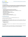
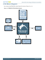
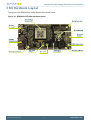
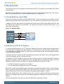
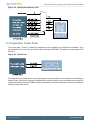
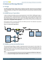
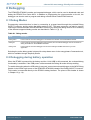
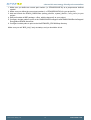
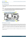
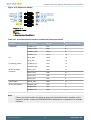
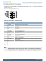
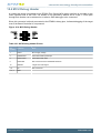
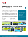
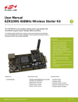
...the world's most energy friendly microcontrollers
USER MANUAL
Starter Kit EFM32ZG-STK3200
The EFM32 Zero Gecko Starter Kit is a feature rich platform for evaluation,
prototyping and application development for the EFM32 Zero Gecko MCU family
with the ARM Cortex-M0+ CPU core.
Main features:
• Silicon Labs EFM32 Zero Gecko Microcontroller with 32 KB Flash and 4KB RAM EFM32ZG222F32.
• Advanced Energy Monitoring provides real-time information about the energy
consumption of an application or prototype design.
• On-board debugger with the possiblity to debug external targets.
• 128x128 pixel Memory-TFT LCD
• Expansion Header and Breakout Pads for easy prototyping of custom hardware.
...the world's most energy friendly microcontrollers
1 Introduction
1.1 Description
The EFM32ZG-STK3200 is an excellent starting point to get familiar with the EFM32 Zero Gecko
microcontrollers. The kit contains a few buttons and LEDs, some capactive touch pads and a very low
power Memory LCD-TFT display. In addition to demonstrating the EFM32 Zero Gecko's capabilities, the
kit can also serve as a good starting point for application development.
1.2 Features
•
•
•
•
•
•
•
•
•
•
EFM32ZG222F32 MCU with 32 KB Flash and 4 KB RAM.
Advanced Energy Monitoring system for precise current tracking.
Integrated SEGGER J-Link USB debugger/emulator with debug out functionality.
20 pin expansion header.
Breakout pads for easy access to I/O pins.
Power sources include USB and CR2032 battery.
2 user buttons, 2 user LEDs
2 capacitve touch pads
Ultra low power 128x128 pixel Memory-LCD
Crystals for LFXO and HFXO: 32.768kHz and 24.000MHz.
1.3 Getting Started
The first step to get started with your new EFM32ZG-STK3200 is to go to
[http://www.energymicro.com/simplicity]
The Simplicity Studio software package contains all the tools, drivers, software examples and
documentation needed to use the EFM32 Zero Gecko Starter Kit. Some important tools for use with the
EFM32ZG-STK3200 are:
• energyAware Commander
• energyAware Profiler
The energyAware Commander is a tool for updating the kit's firmware, programming the MCU and
launching demos.
The energyAware Profiler is the PC-side interface to the Advanced Energy Monitor. It provides the
possibility to do real-time voltage and current monitoring of a running user application.
2013-10-08 - t0032_1.00
2
www.silabs.com
...the world's most energy friendly microcontrollers
2 Kit Block Diagram
An overview of the EFM32 Zero Gecko Starter Kit is shown in Figure 2.1 (p. 3)
Figure 2.1. EFM32ZG-STK3200 Block Diagram
2013-10-08 - t0032_1.00
3
www.silabs.com
...the world's most energy friendly microcontrollers
3 Kit Hardware Layout
The layout of the EFM32 Zero Gecko Starter Kit is shown below.
Figure 3.1. EFM32ZG-STK3200 hardware layout
2013-10-08 - t0032_1.00
4
www.silabs.com
...the world's most energy friendly microcontrollers
4 Power Supply and Reset
4.1 MCU Power Selection
The EFM32 Zero Gecko MCU on the EFM32ZG-STK3200 is designed to be powered by different
sources:
• Through the on-board debugger.
• By a 3V Battery.
• An externally applied power source.
Selecting the power source is done with the slide switch in the lower left corner of the board. Figure 4.1 (p.
5) shows how the different power sources can be selected with the slide switch.
Figure 4.1. EFM32ZG-STK3200 Power Switch
With the switch in the DBG position, an on-board low noise LDO with a fixed output voltage of 3.3V
is used to power the MCU. This LDO sources power from the J-Link USB connector. The Advanced
Energy Monitor is now also connected in series, allowing accurate high speed current measurements
and energy debugging/profiling.
With the switch in the BAT position, a 20mm coin cell battery in the CR2032 socket can be used to
power the device.
Finally, an external power supply can also be connected to the VMCU and GND pins either on the
Expansion Header, or the breakout pads. For this to work the switch must be in the BAT position, and
there should be no battery in the battery holder. See Chapter 10 (p. 14) to find the VMCU and GND
pin locations.
Note
The Advanced Energy Monitor can only measure the current consumption of the EFM32
when the power selection switch is in the DBG position.
4.2 Board Controller Power
The Board Controller is responsible for important features such as the debugger and the Advanced
Energy Monitor, and is powered exclusively through the USB port in the top left corner of the board.
This part of the kit resides on a separate power domain, so a different power source can be selected for
the MCU while retaining debugging functionality. This power domain is also isolated to prevent current
leakage from the MCU power domain when power to the Board Controller is removed.
2013-10-08 - t0032_1.00
5
www.silabs.com
...the world's most energy friendly microcontrollers
4.3 MCU Reset
The EFM32 MCU can be reset by a few different sources:
• The RESET button.
• Through the debugger, either on-board or external.
4.4 Board Controller Reset
The Board Controller can be reset by removing and re-inserting the J-Link USB cable. Removing the
Board Controller USB cable will not reset the EFM32, but whenever the Board Controller is powered up
again, it will issue a RESET to the EFM32 through the on-board debugger.
2013-10-08 - t0032_1.00
6
www.silabs.com
...the world's most energy friendly microcontrollers
5 Peripherals
The starter kit has a set of peripherals that showcase some of the features of the EFM32 Zero Gecko
microcontroller.
Be aware that most EFM32 I/O routed to peripherals are also routed to the breakout pads. This must be
taken into consideration when using the breakout pads for your application.
5.1 Push Buttons and LEDs
The kit has two user push buttons marked PB0 and PB1. They are connected to the EFM32, and are
debounced by RC filters with a time constant of 1ms. The buttons are connected to pins PC8 and PC9.
In addition to the two push buttons, the kit also features two yellow LEDs marked LED0 and LED1, that
are controlled by GPIO pins on the EFM32. The LEDs are connected to pins PC10 and PC11 in an
active-high configuration.
Figure 5.1. Buttons/LEDs
5.2 Memory LCD-TFT Display
A 1.28-inch SHARP Memory LCD-TFT has been added to the board to enable interactive applications
to be developed. The display has a high resolution of 128 by 128 pixels, and consumes very little power.
It is a reflective monochrome display, so each pixel can only be light or dark, and no backlight is needed
in normal daylight conditions.
The display interface consists of an SPI-compatible serial interface and some extra control signals. Data
is sent to the display one line (128 bits) at a time.
The Memory LCD-TFT display is shared with the kit Board Controller, allowing the Board Controller
application to display usefull information when the user application is not using the display. The user
application always controls ownership of the display with EFM_DISP_SELECT (PA8):
• 0: The Board Controller has control of the display
• 1: The user application (EFM32) has control of the display
EFM_DISP_PWR (PA10) enables power to the display, and must be set high in order to use the display.
Data is clocked in on EFM_DISP_MOSI (PD7) when EFM_DISP_CS (PE11) is high, and the clock is
sent on EFM_DISP_SCLK (PC15). The maximum supported clock speed is 1.1 MHz.
EFM_DISP_COM (PE10) is the "COM Inversion" line. It must be pulsed periodically to prevent static
build-up in the display itself. Please refer to the display application information for details on driving the
display:
http://www.sharpmemorylcd.com/resources/LS013B7DH03_Application_Info.pdf
2013-10-08 - t0032_1.00
7
www.silabs.com
...the world's most energy friendly microcontrollers
Figure 5.2. 128x128 pixel Memory LCD
5.3 Capacitive Touch Pads
Two touch pads T1 and T2 utilizing the capacitive touch capability of the EFM32 are available. They
are located on the lower right side of the board, beneath the EFM32. The pads are connected to PC3
and PC4.
Figure 5.3. Touch Pads
The capacitive touch pads work by sensing changes in the capacitance of the pads when touched by a
human finger. Sensing the changes in capacitance is done by setting up the touch pad as part of an RC
relaxation oscillator using the EFM32's analog comparator, and then counting the number of oscillations
during a fixed period of time.
2013-10-08 - t0032_1.00
8
www.silabs.com
...the world's most energy friendly microcontrollers
6 Advanced Energy Monitor
6.1 Usage
The AEM (Advanced Energy Monitor) data is collected by the board controller and can be displayed
by the energyAware Profiler, available through Simplicity Studio. By using the energyAware Profiler,
current consumption and voltage can be measured and linked to the actual code running on the EFM32
in realtime.
6.2 AEM theory of operation
In order to be able to accurately measure current ranging from 0.1uA to 50mA (114dB dynamic range), a
current sense amplifier is utilized together with a dual gain stage. The current sense amplifier measures
the voltage drop over a small series resistor, and the gain stage further amplifies this voltage with two
different gain settings to obtain two current ranges. The transition between these two ranges occurs
around 250uA. Digital filtering and averaging is done within the Board Controller before the samples are
exported to the energyAware Profiler application.
During startup of the kit, an automatic calibration of the AEM is performed. This calibration compensates
for the offset error in the sense amplifiers.
Figure 6.1. Advanced Energy Monitor
6.3 AEM accuracy and performance
The Advanced Energy Monitor is capable of measuring currents in the range of 0.1uA to 50mA. For
currents above 250uA, the AEM is accurate within 0.1mA. When measuring currents below 250uA, the
accuracy increases to 1uA. Even though the absolute accuracy is 1uA in the sub 250uA range, the
AEM is able to detect changes in the current consumption as small as 100nA. The AEM produces 6250
current samples per second.
Note
The current measurement will only be correct when powering the EFM32 from USB power
through the debugger (power select switch set to "DBG").
2013-10-08 - t0032_1.00
9
www.silabs.com
...the world's most energy friendly microcontrollers
7 Board Controller
The kit contains a board controller that is responsible for performing various board-level tasks, such
as handling the debugger and the Advanced Energy Monitor. An interface is provided between the
EFM32 and the board controller in the form of a UART connection. The connection is enabled by setting
the EFM_BC_EN (PD7) line high, and using the lines EFM_BC_TX (PD4) and EFM_BC_RX (PD5) for
communicating.
Specific library functions have been provided in the kit Board Support Package that support various
requests to be made to the board controller, such as quering AEM voltage or current. To use these
functions, the Board Support Package must be installed. See the Chapter 9 (p. 12) to find out more.
Note
The board controller is only available when USB power is connected.
2013-10-08 - t0032_1.00
10
www.silabs.com
...the world's most energy friendly microcontrollers
8 Debugging
The EFM32ZG-STK3200 contains an integrated debugger, which can be used to download code and
debug the EFM32 Zero Gecko MCU. In addition to programming the microcontroller on the kit, the
debugger can also be used to program and debug external Silicon Labs EFM32 devices.
8.1 Debug Modes
Programming external devices is done by connecting to a target board through the provided Debug
IN/OUT Connector, and by setting the debug mode to OUT. The same connector can also be used to
connect an external emulator to the EFM32 MCU on the kit, by setting the debug mode to IN. A summary
of the different supported debug modes are described in Table 8.1 (p. 11) .
Table 8.1. Debug modes
Mode
Description
Debug MCU
In this mode the on-board debugger is connected to the EFM32 on the EFM32ZG-STK3200.
Debug IN
In this mode the on-board debugger is disconnected, and an external debugger can be connected to
debug the EFM32 on the EFM32ZG-STK3200.
Debug OUT
In this mode the on-board debugger can be used to debug an EFM32 mounted in your own
application.
Selecting the active debug mode is done with a drop-down menu in the energyAware Commander tool,
which is available through Simplicity Studio.
8.2 Debugging during battery operation
When the EFM32 is powered by the battery and the J-Link USB is still connected, the on-board debug
functionality is available. If the USB power is disconnected the Debug IN mode will stop working.
To enable debugging when the USB cable is removed, connect an external debugger to the MCU Debug
Header in the bottom right corner of the EFM32ZG-STK3200 instead of the Debug IN/OUT Connector.
This header is connected directly to the EFM32's debug interface. The pinout of this header is shown
in Chapter 10 (p. 14) .
2013-10-08 - t0032_1.00
11
www.silabs.com
...the world's most energy friendly microcontrollers
9 Board Support Package
The Board Support Package (BSP) is a set of C source and header files that enables easy access to,
and control over some board specific features.
Compared to the Silicon Labs EFM32 development kit, the functionality is limited. Unless you need/want
some of the functions contained in the BSP, there is really no need to include or use it. The EFM32 in
the Starter Kit is fully usable without BSP support, and you can use all peripherals in the emlib without
the BSP.
The BSP uses EFM32 peripheral UART0, Location 1 (TX pin PD4, RX pin PD5) on baudrate 115200-8N-1 to communicate with the board controller.
Note
The BSP is only functional when the Starter Kit is USB-powered, using these function calls
with USB disconnected will give unpredictable results.
9.1 Installation location
When installing Simplicity Studio, the BSP will be installed in the user directory, typically in a location
such as
Win7: C:\Users\[username]\AppData\Roaming\energymicro\kits\EFM32ZG_STK3200\
or something similar (depending on your OS/Windows version). All files in the board support package
are prefixed by stk.
9.2 Application Programming Interface
To use the BSP, include the Starter Kit header file, like this:
#include "bsp.h"
All functions in the BSP are prefixed with BSP_. The main initialization routine is defined as
void BSP_Init ( BSP_INIT_STK_BCUART )
and must be called before any access to the STK-functions. This function call will setup the UART
communication channel with a 115200 baud rate. This baud rate depends on the current core clock, so
correct clock configuration should be set before calling this function.
float BSP_CurrentGet ( void )
Returns instant current usage in milliamperes.
float BSP_VoltageGet ( void )
Returns instant voltage (VMCU) reading in volts.
9.3 Example Applications
Under the kits/EFM32ZG_STK3200/examples folder in your installation directory, you will find an
example program using the BSP, with corresponding project/Makefiles for the supported IDEs.
The examples folder also contains examples showing how to use the different peripherals on the
EFM32ZG-STK3200.
9.4 How to include in your own applications
The easiest way to include the BSP in your application is to base your work on the example application
that uses the BSP. The following items are recommended for correct configuration:
2013-10-08 - t0032_1.00
12
www.silabs.com
...the world's most energy friendly microcontrollers
1. Make sure you define the correct part number (i.e. EFM32ZG222F32) as a preprocessor defined
symbol
2. Make sure you define the correct part number (i.e. EFM32ZG222F32) for your project file
3. Add and include the EFM32_CMSIS-files (startup_efm32.s, system_efm32.c, core_cm3.c) to your
project
4. Add and include all BSP package .c-files, with the bsp-prefix to your project
5. Configure include paths to point at the CMSIS/CM3/CoreSupport and CMSIS/CM3/DeviceSupport/
EnergyMicro/EFM32 directories
6. Configure include paths to point to the kits/EFM32ZG_STK3200/bsp directory
Make sure you call "BSP_Init()" early at startup, and you should be all set.
2013-10-08 - t0032_1.00
13
www.silabs.com
...the world's most energy friendly microcontrollers
10 Connectors
10.1 Breakout pads
Many of the EFM32's pins are routed out to "breakout pads" at the top and bottom edges of the kit. A
2.54mm pitch pin header can be soldered in for easy access to these pins. Most I/O pins are available
on these pads.
Note
Some of the breakout pads are shared by on-board EFM peripherals. The schematic must
be consulted to make sure that it is okay to use a shared pin in your application.
Figure 10.1. Breakout pads and Expansion Header
10.2 Expansion header
On the right hand side of the board a right angle 20-pin expansion header is provided to allow connection
of peripherals or plug-in boards. The connecter contains a number of I/O pins that can be used with most
of the EFM32 Zero Gecko's features. Additionally, the VMCU, 3V3 and 5V power rails are also exported.
Figure 10.1 (p. 14) shows the pin assignment of the expansion header. Although the actual pin
mapping varies, the Expansion Headers are to a large extent functionally compatible across all Starter
Kits.
Some of the chip peripheral functions that are available on the Expansion Header are listed in table
Table 10.1 (p. 15) .
2013-10-08 - t0032_1.00
14
www.silabs.com
...the world's most energy friendly microcontrollers
Figure 10.2. Expansion Header
Table 10.1. Some peripheral functions available on Expansion Header
Peripheral
Peripheral pin
MCU Pin
EXP Header pin number
USART/SPI
USART1_TX
PD7
4
USART1_RX
PD6
6
USART1_CLK
PC15
8
USART1_CS
PC14
10
I2C0_SDA
PE12
16
I2C0_SCL
PE13
15
LEUART0_TX
PD4
12
LEUART0_RX
PD5
14
ADC0_CH4
PD4
12
ADC0_CH5
PD5
14
ADC0_CH6
PD6
6
ADC0_CH7
PD7
4
Current DAC
IDAC0_OUT
PB11
11
Analog Comparator
ACMP0_CH0
PC0
3
ACMP0_CH1
PC1
5
ACMP0_CH2
PC2
7
I²C
Low Energy UART
Analog to Digital
Converter
Note
Please note that this table only sums up some of the alternate functions available on the
expansion header. Consult the EFM32ZG222F32 datasheet for a complete list of alternate
functions.
2013-10-08 - t0032_1.00
15
www.silabs.com
...the world's most energy friendly microcontrollers
10.3 Debug IN/OUT Connector
This connector is used for Debug In and Debug Out (see Section 8.1 (p. 11) ). The pinout is described
in Table 10.2 (p. 16) .
Figure 10.3. Debug IN/OUT Connector
Table 10.2. Debug IN/OUT Connector Pinout
Pin
number
Function
Note
1
VTARGET
Target voltage on the debugged application.
2
NC
Not Connected
3
#TRST
JTAG tap reset
5
TDI
JTAG data in
7
TMS/SWDIO
JTAG TMS or Serial Wire data I/O
9
TCK/SWCLK
JTAG TCK or Serial Wire clock
11
RTCK
JTAG RTCK
13
TDO/SWO
JTAG TDO or Serial Wire Output
15
#RESET
Target MCU reset
17
PD
This pin has a 100k pulldown.
18
Cable detect
This signal must be pulled to ground by the external debugger or application for cable
insertion detection.
19
PD
This pin has a 100k pulldown.
4, 6, 8,
10, 12,
14, 16,
20
GND
Note
Although the Debug IN/OUT Connector can support JTAG debugging of external targets,
the EFM32-series of devices do not support JTAG. Any external debugger used with the
Debug IN/OUT Connector in "Debug IN" mode must therefore use Serial Wire Debug.
2013-10-08 - t0032_1.00
16
www.silabs.com
...the world's most energy friendly microcontrollers
10.4 MCU Debug Header
A header with direct connections to the EFM32 Zero Gecko MCU debug interface is provided on the
lower rightmost side of the PCB. The header is not mounted by default, but a 10-pin, 1.27mm pitch
through-hole header can be soldered on to allow a SWD debugger to be connected.
Since this connector is directly connected to the EFM32's debug pins, it allows debugging of the target
even if the Board Controller is not powered.
Figure 10.4. MCU Debug Header
Table 10.3. MCU Debug Header Pinout
Pin
number
Function
Note
1
VMCU
MCU supply voltage
2
SWDIO/TMS
Serial Wire Data Input/Output
4
SWCLK/TCK
Serial Wire Clock input
6
SWO/TDO
Not Connected on the EFM32ZG-STK3200
10
nRESET
Target CPU reset signal
7, 8
NC
Not Connected
3, 5, 9
GND
2013-10-08 - t0032_1.00
17
www.silabs.com
...the world's most energy friendly microcontrollers
11 Integrated Development Environments
The Energy Micro software packages contain various examples in source form to use with the Starter
Kit. The following IDEs are supported.
11.1 IAR Embedded Workbench for ARM
An evaluation version of IAR Embedded Workbench for ARM is included on a CD in the EFM32ZGSTK3200 package. Check the quick start guide for where to find updates, and IAR's own documentation
on how to use it. You will find the IAR project file in the
iar
subfolder of each project
11.2 Atollic TrueSTUDIO for ARM
See the quick start guide for download details for Atollic TrueSTUDIO for ARM. You will find TrueStudio
project files in the
atollic
subfolder of each project.
11.3 Rowley Associates - CrossWorks for ARM
See the quick start guide for download details for CrossWorks for ARM. You will find CrossWorks project
files in the
rowley
subfolder of each project.
11.4 CodeSourcery - Sourcery G++
See the quick start guide for download details for Sourcery G++. The
codesourcery
subfolder contains Makefiles for use with the Sourcery G++ development environment.
11.5 Keil - MDK-ARM
See the quick start guide for download details for evaluation versions of Keil MDK-ARM. The
arm
subfolder in each project contains project files for MDK-ARM. Please see the MDK-ARM documentation
for usage details.
2013-10-08 - t0032_1.00
18
www.silabs.com
...the world's most energy friendly microcontrollers
12 energyAware Commander and Upgrades
The energyAware Commander is a program that comes with Simplicity Studio. It can perform various
kit and EFM32 specific tasks.
12.1 eA Commander Operation
This utility gives the ability to program the EFM32, upgrade the kit, lock and unlock devices and more.
Some of the features will only work with Energy Micro kits, while other will work with a generic J-Link
debugger connected. Press the "F1" button, or select the "Help->Help" menu item for a full description.
Figure 12.1. energyAware Commander
12.2 Firmware Upgrades
Upgrading the kit firmware is done through Simplicity Studio. The Studio will automatically check for
new updates on startup.
You can also use the energyAware Commander for manual upgrades. Select the "Kit" icon, use the
"Browse" button to select the correct file ending in ".emz", and press the "Install package button".
2013-10-08 - t0032_1.00
19
www.silabs.com
...the world's most energy friendly microcontrollers
13 Schematics, Assembly Drawings and BOM
The schematics, assembly drawings and bill of materials (BOM) for the EFM32 Zero Gecko Starter Kit
board are available through Simplicity Studio when the kit documentation package has been installed.
2013-10-08 - t0032_1.00
20
www.silabs.com
...the world's most energy friendly microcontrollers
14 Kit Revision History and Errata
14.1 Revision History
The kit revision can be found printed on the box label of the kit, as outlined in the figure below.
Figure 14.1. Revision info
Table 14.1. Kit Revision History
Kit Revision
Released
Description
A00
20.09.2013
Initial Kit Revision.
14.2 Errata
Table 14.2. Kit Errata
Kit Revision
2013-10-08 - t0032_1.00
Problem
Description
21
www.silabs.com
...the world's most energy friendly microcontrollers
15 Document Revision History
Table 15.1. Document Revision History
Revision
Number
Effective Date
Change Description
1.00
08.10.2013
Initial document version.
2013-10-08 - t0032_1.00
22
www.silabs.com
...the world's most energy friendly microcontrollers
A Disclaimer and Trademarks
A.1 Disclaimer
Silicon Laboratories intends to provide customers with the latest, accurate, and in-depth documentation
of all peripherals and modules available for system and software implementers using or intending to use
the Silicon Laboratories products. Characterization data, available modules and peripherals, memory
sizes and memory addresses refer to each specific device, and "Typical" parameters provided can and
do vary in different applications. Application examples described herein are for illustrative purposes
only. Silicon Laboratories reserves the right to make changes without further notice and limitation to
product information, specifications, and descriptions herein, and does not give warranties as to the
accuracy or completeness of the included information. Silicon Laboratories shall have no liability for
the consequences of use of the information supplied herein. This document does not imply or express
copyright licenses granted hereunder to design or fabricate any integrated circuits. The products must
not be used within any Life Support System without the specific written consent of Silicon Laboratories.
A "Life Support System" is any product or system intended to support or sustain life and/or health, which,
if it fails, can be reasonably expected to result in significant personal injury or death. Silicon Laboratories
products are generally not intended for military applications. Silicon Laboratories products shall under no
circumstances be used in weapons of mass destruction including (but not limited to) nuclear, biological
or chemical weapons, or missiles capable of delivering such weapons.
A.2 Trademark Information
Silicon Laboratories Inc., Silicon Laboratories, the Silicon Labs logo, Energy Micro, EFM, EFM32, EFR,
logo and combinations thereof, and others are the registered trademarks or trademarks of Silicon
Laboratories Inc. ARM, CORTEX, Cortex-M3 and THUMB are trademarks or registered trademarks
of ARM Holdings. Keil is a registered trademark of ARM Limited. All other products or brand names
mentioned herein are trademarks of their respective holders.
2013-10-08 - t0032_1.00
23
www.silabs.com
...the world's most energy friendly microcontrollers
B Contact Information
Silicon Laboratories Inc.
400 West Cesar Chavez
Austin, TX 78701
Please visit the Silicon Labs Technical Support web page:
http://www.silabs.com/support/pages/contacttechnicalsupport.aspx
and register to submit a technical support request.
2013-10-08 - t0032_1.00
24
www.silabs.com
...the world's most energy friendly microcontrollers
Table of Contents
1. Introduction .............................................................................................................................................. 2
1.1. Description .................................................................................................................................... 2
1.2. Features ....................................................................................................................................... 2
1.3. Getting Started ............................................................................................................................... 2
2. Kit Block Diagram ..................................................................................................................................... 3
3. Kit Hardware Layout .................................................................................................................................. 4
4. Power Supply and Reset ............................................................................................................................ 5
4.1. MCU Power Selection ..................................................................................................................... 5
4.2. Board Controller Power .................................................................................................................... 5
4.3. MCU Reset ................................................................................................................................... 6
4.4. Board Controller Reset .................................................................................................................... 6
5. Peripherals ............................................................................................................................................... 7
5.1. Push Buttons and LEDs ................................................................................................................... 7
5.2. Memory LCD-TFT Display ................................................................................................................ 7
5.3. Capacitive Touch Pads .................................................................................................................... 8
6. Advanced Energy Monitor ........................................................................................................................... 9
6.1. Usage ........................................................................................................................................... 9
6.2. AEM theory of operation .................................................................................................................. 9
6.3. AEM accuracy and performance ........................................................................................................ 9
7. Board Controller ...................................................................................................................................... 10
8. Debugging .............................................................................................................................................. 11
8.1. Debug Modes ............................................................................................................................... 11
8.2. Debugging during battery operation .................................................................................................. 11
9. Board Support Package ............................................................................................................................ 12
9.1. Installation location ........................................................................................................................ 12
9.2. Application Programming Interface ................................................................................................... 12
9.3. Example Applications ..................................................................................................................... 12
9.4. How to include in your own applications ............................................................................................ 12
10. Connectors ........................................................................................................................................... 14
10.1. Breakout pads ............................................................................................................................ 14
10.2. Expansion header ........................................................................................................................ 14
10.3. Debug IN/OUT Connector ............................................................................................................. 16
10.4. MCU Debug Header .................................................................................................................... 17
11. Integrated Development Environments ....................................................................................................... 18
11.1. IAR Embedded Workbench for ARM ............................................................................................... 18
11.2. Atollic TrueSTUDIO for ARM ......................................................................................................... 18
11.3. Rowley Associates - CrossWorks for ARM ....................................................................................... 18
11.4. CodeSourcery - Sourcery G++ ....................................................................................................... 18
11.5. Keil - MDK-ARM ......................................................................................................................... 18
12. energyAware Commander and Upgrades ................................................................................................... 19
12.1. eA Commander Operation ............................................................................................................. 19
12.2. Firmware Upgrades ..................................................................................................................... 19
13. Schematics, Assembly Drawings and BOM ................................................................................................. 20
14. Kit Revision History and Errata ................................................................................................................. 21
14.1. Revision History .......................................................................................................................... 21
14.2. Errata ........................................................................................................................................ 21
15. Document Revision History ...................................................................................................................... 22
A. Disclaimer and Trademarks ....................................................................................................................... 23
A.1. Disclaimer ................................................................................................................................... 23
A.2. Trademark Information ................................................................................................................... 23
B. Contact Information ................................................................................................................................. 24
B.1. ................................................................................................................................................. 24
2013-10-08 - t0032_1.00
25
www.silabs.com
...the world's most energy friendly microcontrollers
List of Figures
2.1. EFM32ZG-STK3200 Block Diagram ........................................................................................................... 3
3.1. EFM32ZG-STK3200 hardware layout .......................................................................................................... 4
4.1. EFM32ZG-STK3200 Power Switch ............................................................................................................. 5
5.1. Buttons/LEDs ......................................................................................................................................... 7
5.2. 128x128 pixel Memory LCD ...................................................................................................................... 8
5.3. Touch Pads ........................................................................................................................................... 8
6.1. Advanced Energy Monitor ........................................................................................................................ 9
10.1. Breakout pads and Expansion Header ..................................................................................................... 14
10.2. Expansion Header ............................................................................................................................... 15
10.3. Debug IN/OUT Connector ..................................................................................................................... 16
10.4. MCU Debug Header ............................................................................................................................ 17
12.1. energyAware Commander ..................................................................................................................... 19
14.1. Revision info ...................................................................................................................................... 21
2013-10-08 - t0032_1.00
26
www.silabs.com
...the world's most energy friendly microcontrollers
List of Tables
8.1. Debug modes .......................................................................................................................................
10.1. Some peripheral functions available on Expansion Header ..........................................................................
10.2. Debug IN/OUT Connector Pinout ............................................................................................................
10.3. MCU Debug Header Pinout ...................................................................................................................
14.1. Kit Revision History .............................................................................................................................
14.2. Kit Errata ...........................................................................................................................................
15.1. Document Revision History ...................................................................................................................
2013-10-08 - t0032_1.00
27
11
15
16
17
21
21
22
www.silabs.com