1
U-Camera User Manual -
Table of Contents
1 General System Introduction.............................................................................................4
1.1 U-Camera Elements...................................................................................................4
1.2 Concept of system operation......................................................................................5
2 U-Camera Board................................................................................................................6
3 U-Camera Gimbal..............................................................................................................7
3.1 Mechanical Mounting..................................................................................................7
3.1.1 Vehicle considerations.........................................................................................7
3.1.2 Mounting positions..............................................................................................7
3.1.3 Vibration isolation................................................................................................8
3.1.3.1 Combustion engine vehicles / helicopters...................................................8
3.1.3.2 Electrical multicopters..................................................................................8
3.1.3.3 Electrical fixed wing vehicles.......................................................................8
3.2 Video Transmitter........................................................................................................8
4 U-Camera Operation..........................................................................................................9
4.1 Powering U-Camera...................................................................................................9
4.2 Pointing modes...........................................................................................................9
4.3 GPS Configuration......................................................................................................9
4.4 Vehicle Angles..........................................................................................................10
4.5 Maximum Ratings.....................................................................................................10
5 Communication Protocol..................................................................................................11
5.1 Protocol general description.....................................................................................11
5.2 Packet structure........................................................................................................11
5.3 Checksum Calculation..............................................................................................12
5.4 Data formats and structure.......................................................................................13
5.5 Protocol Structure.....................................................................................................13
5.5.1 Non Volatile Memory Category (Cat: 0x04)......................................................13
5.5.1.1 Save configuration to NV memory (Cat: 0x04, ID: 0x01)...........................13
5.5.2 Device Information Category (Cat: 0x08)..........................................................14
5.5.2.1 Report Gimbal Version (Cat: 0x08, ID: 0x01)............................................14
5.5.2.2 Request Gimbal Version (Cat: 0x08, ID: 0x02)..........................................14
5.5.3 Gimbal Category (Cat: 0x09)............................................................................14
5.5.3.1 Set Mode Packet (Cat: 0x09, ID: 0x01).....................................................14
5.5.3.2 Report Mode Packet (Cat: 0x09, ID: 0x02)................................................15
5.5.3.3 Set gimbal Rates (Cat: 0x09, ID: 0x03).....................................................15
5.5.3.4 Report gimbal Rates (Cat: 0x09, ID: 0x04)................................................15
5.5.3.5 Set gimbal Angles (Cat: 0x09, ID: 0x05)....................................................15
5.5.3.6 Report gimbal Angles (Cat: 0x09, ID: 0x06)..............................................16
5.5.4 Camera Category (Cat: 0x0A)...........................................................................16
5.5.4.1 Set Camera Zoom Packet (Cat: 0x0A, ID: 0x01).......................................16
5.5.4.2 Report Camera Zoom Packet (Cat: 0x0A, ID: 0x02).................................16
5.5.5 External Feed Category (Cat: 0x0B).................................................................16
5.5.5.1 Send GPS Velocities (Cat: 0x0B, ID: 0x01)...............................................17
5.5.5.2 Send GPS Position and Velocities (Cat: 0x0B, ID: 0x02)..........................17
5.5.5.3 System Position Report (Cat: 0x0B, ID: 0x03)..........................................17
5.5.5.4 Configure GPS Feed (Cat: 0x0B, ID: 0x04)...............................................17
5.5.5.5 Send Vehicle Angles (Cat: 0x0B, ID: 0x05)...............................................18
5.6 Periodic Reports Packets.........................................................................................18
2
U-Camera User Manual 5.7 Protocol Summary....................................................................................................19
6 U-Camera electrical connections.....................................................................................20
6.1 U-Camera main connectors pinout...........................................................................20
6.2 U-Camera Main Harness schematic........................................................................21
Appendix A Mechanical Drawings........................................................................................23
Appendix B Changelog........................................................................................................26
3
U-Camera User Manual - General System Introduction
1 General System Introduction
U-Camera is the Gimbal solution provided by Airelectronics, a state of the art, small formfactor Gimbal designed for small and medium sized UAVs. U-Camera can be mounted on
fixed wing vehicles or rotary wing platforms such as multicopters or helicopters.
The system uses encoders, magnetometers and GPS information to calculate the pointing
with high precision. Four different operation modes are available. Mounted camera
provides a 10X optical zoom and an horizontal resolution of 530 TV Lines.
Based on the same FPGA technology as U-Pilot flight control system, U-Camera is capable
of precise pointing even when mounted on vehicles with high dynamics. As its twin system
U-Pilot, U-Camera is built using a two parallel microprocessor approach:
•
One microprocessor takes care of the state estimation, pointing and control of the
gimbal, using hardware acceleration to calculate high speed algorithms.
•
Another processor handles secondary tasks as managing the camera modules or
the communication with the UAV platform.
Due to the fact that those two processors are working in parallel and there is dedicated
electronics taking care of all the serial ports, sensors, inputs and outputs, the system is
capable of recalculating the gimbal position and control faster than any other system,
providing an excellent video stabilization and pointing.
Using a standard RS-232 communication interface, U-Camera can be easily integrated with
a wide range of systems available on the market.
1.1 U-Camera Elements
A U-Camera system is composed by the following elements:
•
U-Camera Board: is the electronic board that computes the gimbal position and
points and stabilizes it.
•
U-Camera Gimbal: the proper gimbal, contains the video module, motors and
sensors.
•
U-Camera Harness: connects U-Camera Board and U-Camera Gimbal and provides
the required connections such as power supply, command interface or video output.
Optionally, U-Camera system can include the following extra elements:
•
GPS Antenna: if the embedded GPS chip is to be used, an external GPS antenna
must be connected. Otherwise, GPS velocities can be externally provided.
•
Video transmitter: in order to send the video feed from the vehicle to the ground
station, a video transmitter and receiver is required.
4
U-Camera User Manual - General System Introduction
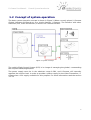
1.2 Concept of system operation
The basic system operation concept is shown in Figure 1. When correctly placed, U-Camera
Gimbal, Harness and Board act as a single element, U-Camera. The interface with other
elements (FCS, Video transmitter) is done via U-Camera Harness.
Figure 1: System concept
The vehicle Flight Control System (FCS) is in charge of managing the gimbal, commanding
the required mode/angles/rates.
The power supply must be in the absolute range 9-28V, and U-Camera will internally
regulate the tension level. In order to provide a power supply for the Video Transmitter, UCamera has a 12V supply available for this purpose. For more information read the section
3.1.3.3
5
U-Camera User Manual - U-Camera Board
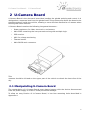
2 U-Camera Board
U-Camera Board is the electronic board that handles the gimbal pointing and control. It is
designed as a separate item from the gimbal itself. This architecture allows the board to be
placed anywhere inside the vehicle, allowing a more efficient distribution of masses when
working with small vehicles.
U-Camera Board contains the following integrated elements.:
•
Power regulators for video, electronics, and motors.
•
Main FPGA containing the two processors along with multiple logic.
•
GPS receiver
•
ADC for voltage monitoring
•
Thermal sensor
•
Main DB-26 main connector
Figure 2: Mainboard schematic
This board must be placed on the vehicle. If the on-board GPS is to be used, receiver
antenna should be located on the upper part of the vehicle to obtain the best view of the
sky.
2.1 Manipulating U-Camera Board
The manipulation of U-Camera Board must always happen with the device disconnected
from the power supply in order to avoid permanent damage.
To allow an easy fixation of U-Camera Board, it has four mounting holes described in
Appendix A.
6
U-Camera User Manual - U-Camera Gimbal
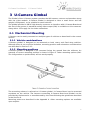
3 U-Camera Gimbal
The Gimbal of the U-Camera system contains the IMU sensors, motors and encoders along
with the video module. U-Camera Gimbal is designed to have a small factor and low
weight (<500grams), so its suitable for small vehicles.
The gimbal provides a DB-26 high density connector to interface with U-Camera Board and
the rest of the system. A standard analog video output (PAL) is available on this connector
along with a 12V supply for the video transmitter.
3.1 Mechanical Mounting
U-Camera can be easily mounted on multiple types of vehicles as described in the current
section.
3.1.1 Vehicle considerations
U-Camera gimbal is designed to be mounted on both rotary and fixed wing vehicles.
Although there is not a vehicle limitation, mounting position and orientation considerations
are described in Section 3.1.2.
3.1.2 Mounting positions
U-Camera gimbal is designed to be mounted facing the ground from the airframe. An
example of correct mounting position is shown in Figure 3. Other mounting options (RollTilt configuration or upside down) will not work properly.
The mounting scheme is referred to U-Camera gimbal, U-Camera Board can be mounted
anywhere on the vehicle. The harness connecting U-Camera Board and Gimbal can be
provided by Airelectronics or manufactured by the client following the guidelines described
in the Section 6.
Mounting points are described in the Appendix A. Other mounting options are available
upon request.
7
U-Camera User Manual - U-Camera Gimbal
3.1.3 Vibration isolation
In order to obtain a satisfactory video experience, it is recommended to isolate the gimbal
from the vibrations that may be present in the vehicle. This is specially important in
vehicles powered by internal combustion engines or helicopters. Regarding vibration
isolation, we can consider 3 types of vehicles:
•
Combustion engine vehicles and all kind of helicopters
•
Electrical multi-copters.
•
Electrical fixed-wing vehicles.
3.1.3.1 Combustion engine vehicles / helicopters
If U-Camera is to be mounted on this type of vehicles, the use of silent blocks is
mandatory. If the Gimbal is not isolated from the vibrations from the vehicle, the images
provided by U-Camera may not be satisfactory and the gimbal may suffer permanent
damage.
3.1.3.2 Electrical multicopters
When mounted on electrical vehicles, specially on multicopters, the use of silent blocks is
highly recommended to obtain high quality images, although damaging the gimbal is less
likely.
3.1.3.3 Electrical fixed wing vehicles
U-Camera can be mounted on electrical fixed vehicles without vibration isolation, although
the use of silent blocks may improve quality of the images.
3.2 Video Transmitter
U-Camera Gimbal connector provide a power supply at 12V (1A max) for a video
transmitter supply. The pins providing the 12V and ground are described in the main
connection Section 6. Using this power supply the transmitter can be connected directly to
the gimbal without external regulators, while maintaining the transmitter isolated from the
rest of the system.
8
U-Camera User Manual - U-Camera Operation
4 U-Camera Operation
4.1 Powering U-Camera
Before powering U-Camera, all the harness and wiring must be connected. U-Camera
system is not ready for hot-plugging, and powerup without all the harness connected may
damage the electronics.
U-Camera accepts input voltages from 9 to 28V. IMPORTANT: if the power supply is above
17V, active cooling of U-Camera Board is highly recommended to avoid permanent
damage.
Upon power-up, the camera will point momentarily to Pan 0º and Tilt 0º and then will start
to stabilize in Angles Mode (Defined in Section 4.2).
4.2 Pointing modes
U-Camera accepts different modes in order to satisfy various pointing operations:
•
Angles Mode: Angles Mode will point the gimbal to the angles provided by Set
Gimbal Angles Packet (Section 5.5.5). Note that the Gimbal will try to stabilize the
camera while maintaining the Pan-Tilt angles. This will stabilize the image less
accurately that the Rates Mode.
•
Rates Mode: Rates Mode will completely stabilize the camera. The Gimbal will
keep the camera pointing to a fixed direction in the space. The stabilization point
can be modified using the Set Gimbal Rates Packet (Section 5.5.5.3).
•
STOW: The mode will protect the camera lens pointing it to the angle tilt = +90 °
and pan = 0°.
•
Pilot: The pilot mode will point the gimbal to tilt = 0° and pan = 0° to provide the
front view from the vehicle. This mode has a soft stabilization.
4.3 GPS Configuration
U-Camera can work with and without GPS input. However, it is recommended to work with
GPS input to provide the maximum pointing accuracy.
The GPS source can be selected according to the protocol description in section 5.5.5.4,
being the following options available.
•
Internal GPS: U-Camera will use the onboard GPS receiver to get the position and
velocities. In this case, the GPS antenna must be placed correctly on the vehicle
and connected to U-Camera Board.
•
External Feed: U-Camera will use the position and velocities send from the
controller as described in the communication protocol (Sections 5.5.5.1 and
5.5.5.2).
If no antenna is connected and no external feed is provided, U-Camera will continue
working but pointing accuracy may decrease in high dynamics vehicles.
9
U-Camera User Manual - U-Camera Operation
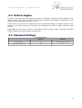
4.4 Vehicle Angles
In order to provide the best pointing accuracy, U-Camera accepts the Euler Angles of the
vehicle (Yaw, Pitch, Roll) as input. The packet providing this angles is described in the
communication protocol (Section 5.5.5.5).
If this packet is received, U-Camera will use the provided angles as vehicle angles. If the
packet is not being received U-Camera will calculate the vehicle angles from the GPS
source.
Depending on the type of vehicle and Flight Control System used, externally provided
vehicle angles will provide better performance.
4.5 Maximum Ratings
Input Characteristics
Minimum
Maximum
Input Voltage
9V
17V / 28V (with cooling)
Operating Temperature
-15 ºC
+70 ºC
10
U-Camera User Manual - Communication Protocol
5 Communication Protocol
5.1 Protocol general description
U-Camera communicates using the U-Camera Serial Protocol, UCSP. UCSP is a serial
protocol that allows the controller (indicated as CTRL in this document) to command UCamera Gimbal (GMB in this document).
Source
Destination
Main Function
CTRL(Controller)
GMB(U-Camera)
Command and configuration
GMB(U-Camera)
CTRL(Controller)
Status Report and Answer
UCSP is a standard serial protocol at 115200 bps, 1 stop bit and no parity. The
communication messages are based on a standard packet structure defined in the next
Section 5.2.
UCSP
Configuration
Serial Speed
Stop bit
Parity
115200bps
1
None
The downstream flow (CTRL → GMB) is controlled by the master, which decides the packets
to be sent and when to send them. Although not required, it is recommended to send
periodically (~10Hz at least) packets regarding the command mode and desired
angles/rates.
The upstream flow (GMB → CTRL) is handled by U-Camera sending periodically reports of
its status. When CTRL sends a request, GMB replays to the request before sending more
periodic reports. The periodic report packets are described in the Section 5.6.
5.2 Packet structure
The UCSP protocol is based on packets with variable length. The packet structure is
described in the following tables.
0
1
2
3
4
...
N+3
N+4
N+5
SYNC BYTE
CATEGORY
ID
LENGTH
PAYLOAD1
...
PAYLOADN
CHK_A
CHK_B
Position
Name
Description
0
Synchronization Byte 0xCC
Synchronization Byte
1
Category number
Upcoming Packet Category
2
Id number
Upcoming Packet ID number
3
Packet Length(N)
Upcoming data Length
[4, N+3]
Payload
Payload Content
N+4
Checksum A
N+5
Checksum B
Note that the Packet Length Number is referred to Payload, meaning that the complete
packet is composed by N + 6 bytes.
11
U-Camera User Manual - Communication Protocol
5.3 Checksum Calculation
As described in the previous section, the UCSP packets have two checksum bytes to
determine the integrity of the packet.
This checksum is the 8-bit Fletcher algorithm, which is used in the TCP standard (RFC
1145).
Checksum A (CK_A) and Checksum B (CK_B) must be initialized to zero (0x00).
For each byte of the payload the byte is added to CK_A and then CK_B is the result of
adding the previous CK_B value to CK_A.
When adding to CK_A and CK_B, values overflowing the 8 bits should be trimmed to 8 bit
with a 0xFF mask if the data type is wider than 8 bits.
The checksum involves all the packet bytes except for the checksum bytes themselves.
The packet is valid if the calculated CK_A and CK_B values are identical to the last two
bytes of the packet.
A pseudocode for checksum calculation is provided in the following figure:
unsigned char CK_A, CK_B
CK_A = 0,CK_B = 0
For ( I = 0; I<N; I++)
{
CK_A = CK_A + Buffer[I]
CK_B = CK_B + CK_A
}
Pseudo-code for check sum calculation
Figure 4: Pseudo-code for checksum calculation
For testing purposes, the following test packet is provided:
0
1
2
3
4
5
6
7
8
9
10
11
12
CK_A
CK_B
0xCC
0x01
0x02
0x09
0x01
0x02
0x03
0x04
0x05
0x06
0x07
0x08
0x09
0xFC
0x74
Figure 5:Example Packet
12
U-Camera User Manual - Communication Protocol
5.4 Data formats and structure
The data used in UCSP protocol is always sent using little endian scheme. The following
table shows the order for the different data types used in the U-Camera protocol. The
position indicates the order used for sending the bytes, meaning that Position 0 byte is
sent before Position 1 byte and so on.
Type
Position 0
Position 1
Position 2
Position 3
Integer (int)
Int [7:0]
Int [15:8]
Int [23:16]
Int [31:24]
Unsigned Int (uint)
Uint [7:0]
Uint [15:8]
Uint [23:16]
Uint [31:24]
Float [23:16]
Float [31:24]
Float (float)
Float [7:0]
Float [15:8]
Short Int (int16)
Int16 [7:0]
Int16 [15:8]
Unsigned Short Int (uint16)
Uint16 [7:0]
Uint16 [15:8]
Byte/Char (byte)
Byte [7:0]
5.5 Protocol Structure
As described in section 5.2, the protocol packets are defined by a category and Id byte.
Categories are meant to group multiple commands related to the same element, the
available categories in the protocol are listed in the following table.
Category Byte
Category Name
Brief
0x04
Non Volatile Memory
Commands related to the saving of the current configuration.
0x08
Device Information
Device Information
0x09
Gimbal
Gimbal Command and Report
0x0A
Camera
Camera Module Command and Report
0x0B
External Feed
External information provided to the gimbal
5.5.1 Non Volatile Memory Category (Cat: 0x04)
This category allows to save the current configuration to the non-volatile memory using
the “Save Configuration” packet.
Packet ID Byte
Packet Name
Source
Destination
Brief
0x01
Save Configuration
CTRL
GMB
Save configuration to Non Volatile Memory
5.5.1.1 Save configuration to NV memory (Cat: 0x04, ID: 0x01)
To save the current configuration ton the non volatile memory, just send this packet with
no payload. During the process of saving the configuration, the gimbal will not send
telemetry or respond to commands, although the stabilization and pointing will work
normally. This process usually takes around one second.
Sync Byte Category Byte
0xCC
0x04
ID Byte
Length Byte
CK_A
CK_B
0x01
0x00
0xD1
0x3E
DO NOT use this command during flight and remember to use a stable power supply. A
loss of power during the saving process may cause permanent damage to the unit.
13
U-Camera User Manual - Communication Protocol
5.5.2 Device Information Category (Cat: 0x08)
Device Information category contains the packets required to request and report the
firmware version and the serial number of the unit.
Packet ID Byte
Packet Name
Source
Destination
Brief
0x01
Report Version
GMB
CTRL
Report Gimbal Software Version / Serial Number
0x02
Request Version
CTRL
GMB
Request Gimbal Software Version / Serial Number
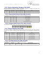
5.5.2.1 Report Gimbal Version (Cat: 0x08, ID: 0x01)
The payload of the gimbal version report uses the following structure:
Payload Position
Data Type
Data Description
0
int16
MB Serial Number
1
int16
SB Serial Number
2
int32
CPU0 Version
3
int32
CPU1 Version
4
int16
Non-Volatile Memory Version
5.5.2.2 Request Gimbal Version (Cat: 0x08, ID: 0x02)
To request the gimbal version information an empty packet is required.
Sync Byte Category Byte
0xCC
ID Byte
Length Byte
CK_A
CK_B
0x02
0x00
0xD6
0x4C
0x08
5.5.3 Gimbal Category (Cat: 0x09)
The Gimbal category refers to the control of the pointing system itself. This category
contains the packets regarding mode selection/report and rates/angles command and
report.
Packet ID Byte
Packet Name
Source
Destination
Brief
0x01
Set Mode
CTRL
GMB
Set Gimbal Mode
0x02
Report Mote
GMB
CTRL
Report Gimbal Mode
0x03
Set Gimbal Rates
CTRL
GMB
Set Gimbal Rates
0x04
Report Gimbal Rates
GMB
CTRL
Report Gimbal Rates
0x05
Set Gimbal Angles
CTRL
GMB
Set Gimbal Angles
0x06
Report Gimbal Angles
GMB
CTRL
Report Gimbal Angles
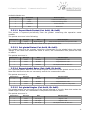
5.5.3.1 Set Mode Packet (Cat: 0x09, ID: 0x01)
The packet allows to set the pointing mode of the gimbal.
Data Position
Data Type
Data
Data Description
0
int16
Mode Number
Mode number described in the next table
14
U-Camera User Manual - Communication Protocol
Available Modes are:
Mode Number
Mode Name
Mode Description
0
Angles
Command Gimbal Angles
1
Rates
Command Pointing Rates
2
Safe Mode
Protect the Lens
3
PIlot
Front View
5.5.3.2 Report Mode Packet (Cat: 0x09, ID: 0x02)
This packet is reported periodically from the gimbal containing the operative mode
number.
The packet structure is the following:
Data Position
Data Type
Data
Mode Description
0
int16
Mode Number
Mode number described in the previous table
The mode definition is the same described in the previous section.
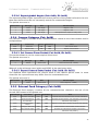
5.5.3.3 Set gimbal Rates (Cat: 0x09, ID: 0x03)
The gimbal rates are the angular velocities commanded to the gimbal when the mode
“Rates” is set. Note that unless this mode is active, the commands in this packet will take
no effect.
The packet structure is:
Data Position
Data Type
Data
Data Description
0
int16
Pan Rate
degrees/Second * 100
1
int16
Tilt Rate
degrees/Second * 100
2
int16
Roll Rate
Not Implemented, fill with Zero
5.5.3.4 Report gimbal Rates (Cat: 0x09, ID: 0x04)
The reported gimbal rates are the actual angular velocities of the gimbal around its axis.
Note that these values do not necessarily match the commanded rates.
The packet structure is:
Data Position
Data Type
Data
Data Description
0
int16
Pan Rate
degrees/Second * 100
1
int16
Tilt Rate
degrees/Second * 100
2
int16
Roll Rate
Not Implemented, report is always Zero
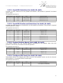
5.5.3.5 Set gimbal Angles (Cat: 0x09, ID: 0x05)
The gimbal angles are the position of the gimbal referred to its axis. Note that unless the
mode angle is active, the commands in the packet will take no effect.
The packet structure is:
Data Position
Data Type
Data
Data Description
0
int16
Pan Angle
degrees * 100
1
int16
Tilt Angle
degrees * 100
2
int16
Roll Angle
Not Implemented, fill with Zero
15
U-Camera User Manual - Communication Protocol
5.5.3.6 Report gimbal Angles (Cat: 0x09, ID: 0x06)
The reported gimbal angles represent the current position of the gimbal referred to its axis.
Note that these values do not necessarily match the commanded angles.
The packet structure is:
Data Position
Data Type
Data
Data Description
0
int16
Pan Angle
degrees * 100
1
int16
Tilt Angle
degrees * 100
2
int16
Roll Angle
Not Implemented, report is always Zero
5.5.4 Camera Category (Cat: 0x0A)
The camera category contains all the communications related to the video module and its
configurations.
Packet ID Byte
Packet Name
Source
Destination
Brief
0x01
Set Zoom
CTRL
GMB
Set Camera Zoom
0x02
Report Zoom
GMB
CTRL
Report Camera Zoom
5.5.4.1 Set Camera Zoom Packet (Cat: 0x0A, ID: 0x01)
This packet allows to set the camera optical zoom level.
The packet structure is:
Data Position
Data Type
Data
Data Description
0
uint16
Zoom Value
Zoom Command (0 - 16383)
Where 0 is the minimum zoom (wide) and 16383 is the maximum (tele).
5.5.4.2 Report Camera Zoom Packet (Cat: 0x0A, ID: 0x02)
The reported zoom represents the current value of the camera optical zoom. In some
situations the reported zoom may differ from the commanded zoom.
The packet structure is:
Data Position
Data Type
Data
Data Description
0
int16
Zoom Value
Zoom Report (0 - 16383)
5.5.5 External Feed Category (Cat: 0x0B)
The External Feed category contains all the communications related to the use of the
aircraft GPS instead of the gimbal one.
Packet ID Byte
Packet Name
Source
Destination
Brief
0x01
Send GPS Velocities
CTRL
GMB
Provides the GPS Velocities to be used in estimation
0x02
Send GPS Position
and Velocities.
CTRL
GMB
Provides the GPS Position and Velocities to be used in
estimation and pointing
0x03
System Position
Report
GMB
CTRL
Reports current GPS Latitude, Longitude and Altitude
0x04
Configure GPS Feed
CTRL
GMB
Switch between onboard GPS and aircraft GPS
0x05
Send Vehicle Angles
CTRL
GMB
Provides the Vehicle Euler Angles to be used in
estimation and pointing
16
U-Camera User Manual - Communication Protocol
5.5.5.1 Send GPS Velocities (Cat: 0x0B, ID: 0x01)
Provides the GPS velocities for the gimbal calculations. This packet is ignored if on-board
GPS is used.
The packet structure is:
Data Position
Data Type
Data
Data Description
0
int32
GPS Vel. North
meters/second * 1e2
1
int32
GPS Vel. Est
meters/second * 1e2
2
int32
GPS Vel. Down
meters/second * 1e2
5.5.5.2 Send GPS Position and Velocities (Cat: 0x0B, ID: 0x02)
Provides the GPS velocities and positions for the gimbal calculations. This packet is ignored
if on-board GPS is used.
The packet structure is:
Data Position
Data Type
Data
Data Description
0
int32
GPS Pos Lat
degrees * 1e7
1
int32
GPS Pos Lon
degrees * 1e7
2
int32
GPS Pos Alt
meters * 1e5
3
int32
GPS Vel. North
meters/second * 1e2
4
int32
GPS Vel. Est
meters/second * 1e2
5
int32
GPS Vel. Down
meters/second * 1e2
5.5.5.3 System Position Report (Cat: 0x0B, ID: 0x03)
This packet reports the last system position calculated in the gimbal. Note that this
position is not strictly the same as the GPS position.
The packet structure is:
Data Position
Data Type
Data
Data Description
0
int32
System Pos Lat
degrees * 1e7
1
int32
System Pos Lon
degrees * 1e7
2
int32
System Pos Alt
meters * 1e5
5.5.5.4 Configure GPS Feed (Cat: 0x0B, ID: 0x04)
This packet allows to configure the GPS source for the gimbal, which can be the internal
GPS module or an external feed via serial port.
The packet structure is:
Data Position
Data Type
Data
Mode Description
0
byte
gps feed config
0: use internal GPS Module
1: use data from serial feed
17
U-Camera User Manual - Communication Protocol
5.5.5.5 Send Vehicle Angles (Cat: 0x0B, ID: 0x05)
Provides the vehicle Euler angles for the gimbal calculations.
The packet structure is:
Data Position
Data Type
Data
Data Description
0
int32
Yaw
degrees * 1e4
1
int32
Pitch
degrees * 1e4
2
int32
Roll
Degrees * 1e4
5.6 Periodic Reports Packets
U-Camera (GMB) periodically send report packets to inform the controller (CTRL) of the
gimbal status. This periodic packet are listed in the following table.
Category
ID
Packet
0x08
0x01
U-Camera Version Packet
0x09
0x02
Mode Report
0x09
0x04
Rates Report
0x09
0x06
Angles Report
0x0A
0x02
Zoom Report
0x0B
0x03
Position Report
Note that the frequency of this packets may vary from one to another. For example, the
Version packet is reported slower than the Angles or Rates report.
18
U-Camera User Manual - Communication Protocol
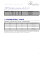
5.7 Protocol Summary
Packet
Sync Byte
Category Byte
Command ID Byte
Length Byte
0x01
0x00
Non Volatile Memory Category
Save configuration to NV Memory
0xCC
0x04
Device Information Category
Report Gimbal Software Version
Request Gimbal Software Version
0xCC
0x08
0x01
0x0E
0xCC
0x08
0x02
0x00
Gimbal Category
Set Mode
0xCC
0x09
0x01
0x02
Report Mode
0xCC
0x09
0x02
0x02
Set Gimbal Rates
0xCC
0x09
0x03
0x06
Report Gimbal Rates
0xCC
0x09
0x04
0x06
Set Gimbal Angles
0xCC
0x09
0x05
0x06
0xCC
0x09
0x06
0x06
Report Gimbal Angles
Camera Category
Set Camera Zoom
0xCC
0x0A
0x01
0x04
Report Camera Zoom
0xCC
0x0A
0x02
0x04
External Feed Category
Send GPS Velocities
0xCC
0x0B
0x01
0x0C
Send GPS Position and Velocities
0xCC
0x0B
0x02
0x18
Report System Position
0xCC
0x0B
0x03
0x0C
Configure GPS Feed
0xCC
0x0B
0x04
0x01
Send Vehicle Angles
0xCC
0x0B
0x05
0x0C
19
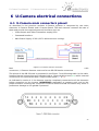
U-Camera User Manual - U-Camera electrical connections
6 U-Camera electrical connections
6.1 U-Camera main connectors pinout
As described in the previous sections U-Camera systems is composed by two main
elements: U-Camera Gimbal and U-Camera Board. The main harness connects the two of
them and provide the required external interfaces such as:
•
Video Output and Video Transmitter supply(12V)
•
Command Interface
•
Main Power Supply: 9-28V (9-17V without active cooling).
Figure 6: U-Camera Harness schematic
Both U-Camera Board and U-Camera Gimbal have DB-26 male conectors. To match this
connectors, U-Camera Harness must end in two DB-26 female connectors.
The pinout of the DB-26 ends is presented in the Figure 7 and following table. In the table,
harness internal connections are indicated with a green double arrow(<->) while external
connections are represented with a single ended arrow (<- or →).
As indicated in section 4.1, the harness must be completely connected to all the elements
before powering up the system. IMPORTANT: remember to connect each end to the
proper element. Crossing the connectors of DB-26 Board and DB-26 Gimbal may result in
permanent damage to the gimbal if powered.
20
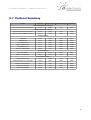
U-Camera User Manual - U-Camera electrical connections
Function
DB26 Gimbal
PIN
Main
Harness
DB26 Board
Video Out
12V Video Tx
0V Video Tx
Internal 01
Internal 02
Internal 03
Internal 04
Internal 05
Internal 06
Internal 07
NC
NC
Internal 08
Internal 09
Internal 10
Internal 11
Internal 12
NC
NC
NC
NC
Internal 13
Internal 14
Internal 15
Internal 16
NC
Sig Video
12V Video
0V Video
01
02
03
04
05
06
07
08
09
10
11
12
13
14
15
16
17
18
19
20
21
22
23
24
25
26
<->
<->
<->
<->
<->
<->
<->
X
X
<->
<->
<->
<->
<->
X
X
->
->
<->
<->
<->
<->
X
<<- / ->
<- / ->
Internal 01
Internal 02
Internal 03
Internal 04
Internal 05
Internal 06
Internal 07
0V
0V
Internal 08
Internal 09
Internal 10
Internal 11
Internal 12
NC
NC
Serial 232 Rx
Serial 232 Tx
Internal 13
Internal 14
Internal 15
Internal 16
NC
NC
DC_Input
0V_Input
Function
Command 232 Rx
Command 232 Tx
Power +
Power -
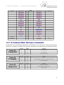
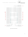
6.2 U-Camera Main Harness schematic
In the Figure 8 a pin-detailed schematic is presented. As for the direct connector-connector
relations, no detail is required. The exernal connections are detailed in the following tables.
Conn J3
Command
Conn J4
P. Supply
Conn J5
Video Out
Pin No.
Name
Function
1
Rx
U-Camera Rx
2
Tx
U-Camera Tx
3
GND
Ground Reference
Pin No.
Name
Function
1
NC
NC
2
Vin
Input Voltage: 9-28V (9-17V without cooling)
3
GND
Ground Reference
Pin No.
Name
Function
1
NC
Video PAL Output
2
Vin
Video 12V(to Video Ground)
3
GND
Video Ground
21
U-Camera User Manual - U-Camera electrical connections
Figure 8: Main Harness Schematic
22
U-Camera User Manual - U-Camera electrical connections
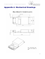
Appendix A Mechanical Drawings
23
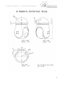
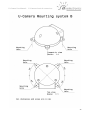
U-Camera User Manual - U-Camera electrical connections
24
U-Camera User Manual - U-Camera electrical connections
Note: other mounting options are available upon request.
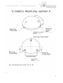
25
U-Camera User Manual - U-Camera electrical connections
26
U-Camera User Manual - U-Camera electrical connections
27
U-Camera User Manual - U-Camera electrical connections
Appendix B Changelog
This annex describes changes introduced to this document.
Date
Changes
2015/11/19
•
Added Mounting Type B
2015/11/18
•
•
Updated some expressions
Corrected Save Configuration packet description
2015/11/03
•
•
Version of document started 1.0
Created Document
If you need a previous
[email protected]
version
of
documentation,
please,
contact
us
at
28