1
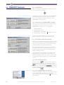
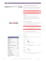
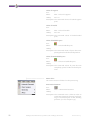
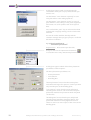
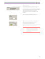
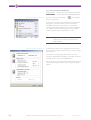
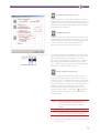
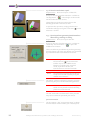
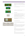
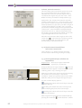
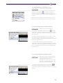
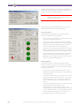
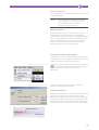
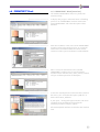
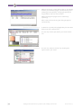
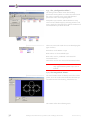
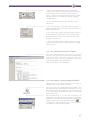
PERFACTORY®
Rapid Prototyping System
2. Getting started with
PERFACTORY® Software Suite
and MAGICS Envisiontec®
Envisiontec GmbH
Elbestraße 10
D-45768 Marl
Germany
Phone:+49 2365 915460
Email:[email protected]
2
Getting started with Perfactory Software Suite and Magics Envisiontec
Version 01/2005
2.1 Disclaimer
This short instruction manual allows the new owner
to quickly put the PERFACTORY® Software Suite and
the Magics Envisiontec® Software into operation and
explains the data preparationn and the build job
generation.
The contents of this documentation is meant to
provide people such as industrial designers, technical
draftsmen, dental laboratory technicians, architects
and model-makers - people involved in the making of
and working with models - with speedy information
about using the PERFACTORY® Software Suite.
Please carefully read this short instruction manual.
Keep this short instruction manual alongside your
workstation for all eventualities.
Envisiontec1 offers a one year limited warranty from
date of Purchase unless longer warranty periods are
required by Law in the country of installation.
Envisiontec warranties that the PERFACTORY® System
sold and all accessories with it are free from defects.
Envisiontec’s reponsibility is limited to repairs or
replacement of defective parts at our discretion.
Envisiontec makes no warranties which extend
beyond the descriptions contained in this Guide. The
User assumes all risks and liability for results obtained
by the user or implementation of the instructions
described herein, weather used singly or in
combination with other designs or products derived
or resulting from the software licensed to the user by
Envisiontec hereunder will not infringe the claims of
domestic or foreign patents. Except for the negligence
of Envisiontec, its agents, representatives or
employees, user shall protect, indemnify and save
harmless Envisiontec of and from any loss, cost,
damage or expense arising from any claim that is in
any way associated with the operation of the
PERFACTORY® system as described in this guide.
Envisiontec shall not be liable for any special or
consequential damages.
Data presented in examples do not necessarily reflect
the actual test results and should not be used as
operating criteria.
1.
Envisiontec does not accept any further warranty
claims or modified warranty limitations.
3
2.2 Introduction
Envisiontec provides you two software packages to
prepare the data for the PERFACTORY® system:
• MAGICS Envisiontec®
• PERFACTORY® Software Suite
Use MAGICS Envisiontec® for model preparation and
support generation for every single model you want
to build. Please read the MAGICS manual for a
detailed description of all functions.
Use PERFACTORY® RP to place the prepared models
and its supports on the building platform and to
generate build jobs for the PERFACTORY® system.
)———————————
2.2.1 Magics Envisiontec:
Use Magics Envisiontec® for data preparing and
support generation:
Model A
MAGICS
Envisiontec®
Unify
Since CAD systems don't always export clean STL files,
correction may be needed before generation support:
• Use the Unify-operation to remove all self
intersections automatically. This avoids that
support structure intersects other model surfaces
than the area to be supported.
Auto Repair
• Use the Auto-repair-operation to repair flipped
triangles, bad edges, gaps...
Model
Orientation
Support
Generation
Stitch
Model A'
Support Model A'
Check now if the model orientation is suitable for the
building process. If not reorient the model.
Save the repaired and reoriented model and start the
support generation - if necessary. Different parameter
settings are available to automatically generate
support structures. They were optimized for various
model geometries (low volume models,high volume
models and die-cast models).
You may edit the support structures generated by the
support module by deleting those supports that you
deem unnecessary based on your experience. For
details on how to edit support structures generated
by the support module Magics Envisiontec® please
refer to the corresponding section in the user manual
for this program.
)———————————
Build Direction
Building Platform
Support
Basement
The support structures necessary for a 3D model
depends largely on its geometry. In order to select
certain supports, you need experience coupled with
detailed knowledge of the building process on the
PERFACTORY® machine. The following gives you a
short overview on what to take into account.
Support structures in the PERFACTORY® machine are
necessary to be able to pull off solidified layer
sections from the basement surface that are not
connected to the building platform / main body.
Model
4
Getting started with Perfactory Software Suite and Magics Envisiontec
Version 01/2005
Since those layer sections are not sufficiently
connected to previously solidified layers they cannot
be pulled off the basement surface together with the
main body of the model.
For this reason support structures must have a certain
minimum density and thickness. This in turn depends
on the area of the cured section to be pulled off.
The accessibility of the support structures must be
taken into account as they need to be removed later
on.
The number of necessary supports depends largely on
the orientation of the 3D model. Consider this when
selecting a suitable orientation for the 3D model.
Use the stitch operation to repair automatically bad
edges created by the support generator. This will
reduce the amount of memory and increase the
slicing speed for data preparing.
Save the generated support into the stl-format.
Do that for every single model you want to build.
)———————————
Model A
Model B
Support of model A
2.2.2 PERFACTORY® Software Suite
The different modules of the PERFACTORY® Software
Suite will help you to administrate the different
modules, to prepare a build job and send it to a
PERFACTORY® machine.
Support of model B
Model
Placement
Slicing
Widening
Merge
Build Job
Generation
PERFACTORY® RP
Perfactory
System
The PERFACTORY® StartCenter allows you to launch
the different modules of the Suite.
Use the module PERFACTORY® RP to group the
repaired and re-orientated models and their
corresponding supports on a virtual building
platform.
After placing you can create a buildjob from the
current scene for the PERFACTORY® machine and send
it to that machine.
Use the module PERFACTORY® Direct to control the
building process at an arbitrary PERFACTORY®
machine.
Use the module PERFACTORY® Job Modifier to modify
the building parameters of an existing build job file.
This module is for advanced user only.
Use the module PERFACTORY®Parameter Editor o
improve building accuracy and reduce material
shrinkage effects by adapting the build platform. This
module is for advanced user only.
5
2.3 PERFACTORY® StartCenter
2.3.1 Introduction
After installing the PERFACTORY® Software Suite an
icon is placed at the desktop
)———————————
A double click at this icon will start the PERFACTORY®
StartCenter. With this program you have a direct
access to the different software modules of the
PERFACTORY® Software Suite.
2.3.2 Direct access to PERFACTORY® modules
After launching PERFACTORY® StartCenter a dialog
box appears. Four different modules of the
PERFACTORY® Software Suite are available:
1
PERFACTORY® RP
2 PERFACTORY® Direct
3 PERFACTORY® Job Modifier
4 PERFACTORY® Job Creator
)———————————
„Advanced“ button
To see the last two modules press the advanced
button at the lower right side of the dialog box.
2.3.3 Description of the four modules
Placing the 3D models at the building platform, slicing
them into layered objects and generating of build
jobs are some of the functions for data processing
usable with the module PERFACTORY® RP.
The module PERFACTORY® Direct is a printer like
interface utility for the PERFACTORY® machine. The
module displays the progress of and information
about a building process.
The two modules PERFACTORY® Job Modifier and
PERFACTORY® Parameter Editor are used to view,
check and modifiy jobfiles resp. the Parameter Editor
to adapt the platform ranges for your PERFACTORY®
System.
2.3.4 The ’minimize’ option
Select the option
to minimize the window of
the StartCenter to the task bar. Select the option
to minimize the StartCenter to the systray. This
will be done if the checkbox
is enabled
and if you have pressed one of the four buttons or the
minimize button
.
)———————————
2.3.5 Close PERFACTORY® StartCenter
To close PERFACTORY® StartCenter click with the right
mouse button at the task bar icon and select
Exit StartCenter. A click at the button
will close the
window too.
6
Getting started with Perfactory Software Suite and Magics Envisiontec
Version 01/2005
2.4 PERFACTORY® RP - Overview
2.4.1 Introduction
Use the module PERFACTORY® RP for data-processing
and for creation of build jobs for the PERFACTORY®
system. The functionality of the user interface can be
described as follows:
)———————————
The user interface of the PERFACTORY® RP module are
divided into eight different areas:
1. Menu
2. Direct access toolbar
3. Explorer Window
4. Information Window
5. Rendering Area
6. Selection of a specific Renderer Mode
7. Toolbar for changing / modifying display properties
8. Memory management
1. Menu
The menu bar gives acces to functions for loading,
processing and saving parts. You find also entries for
generate a build job, prepare the used PERFACTORY®
machine and build your job.
)———————————
2. Direct access toolbar
The toolbar allows a direct access to functions of the
different plug-ins without navigation through the
menu.
)———————————
3. Explorer Window
This window shows the names and different
informations of all loaded objects. If you select a
name the corresponding object will be marked at the
rendering area and you can use data-processing
operations. If the Shift or the Ctrl key is pressed during
a selection more than one object can be selected.
)———————————
4. Information Window
This window contains information of the current
selection like number of points or triangles.
5. Rendering Area
This window shows the rendered object geometry.
7
)———————————
6. Selection of a specific Renderer Mode
This windows allows you to select a rendering
method which shows the data with diffenent level of
detail. You can set the current renderer as default
render by pressing the „Use as Standard“ button.
NOTE:
The higher the level of detail the higher
the used amount of RAM memory.
7. Toolbar for changing and modifying display
properties
Changing point of view, reset to standard view,
switching between parallel and perspective
projection, switch on/off of displaying the building
platform are some of the functions, which are
available at this toolbar.
)———————————
8. Memory management
You can select between two memory managements.
The first is called 'RAM' and holds all data in the main
memory. The second 'Swap' uses swap files. .
NOTE:
Select the 'Swap' option if you process
large data files or if you do not have
enough RAM memory.
2.4.2 PERFACTORY® RP - Menu bar
The next chapter describes briefly the functions of the
menu bar.
)———————————
Menu: File
This menu contains all functions to open, save, print
and build a scene:
New Platform
Icon:
Menu:
File ¬ New Platform
Hotkey:
Ctrl + N
Description: This command creates a new platform
(see chapter 2.5.1).
Open…
Icon:
Menu:
File ¬ Open…
Hotkey:
Ctrl + O
Description: This command opens a dialogbox to load
a data file (see chapter 2.5.2).
8
Getting started with Perfactory Software Suite and Magics Envisiontec
Version 01/2005
Open & Add…
Icon:
Menu:
File ¬ Open & Add…
Hotkey:
Ctrl + H
Description: This command opens a dialog box to load
a data file which will be added to the current scene (see chapter 2.5.2).
Open at last support storage…
Icon:
Menu:
File ¬ Open at last support storage…
Hotkey:
Ctrl + L
Description: This command opens a dialog box to load
a data file. The path where the last support files were saved will be used as
default path (see chapter 2.5.2).
Save as…
Icon:
Menu:
File ¬ Save as…
Hotkey:
Ctrl + S
Description: This command opens a dialog box to save
your data (see chapter 2.5.3).
Close
Icon:
-
Menu:
File ¬ Close
Hotkey:
Ctrl + W
Description: This command closes the current scene.
Estimation of volume, building time…
Icon:
Menu:
File ¬ Estimation of volume, building
time…
Hotkey:
-
Description: This command opens a dialog box to calculate the volume, the estimated building time and costs of the selected parts.
Build…
Icon:
Menu:
File ¬ Build…
Hotkey:
Ctrl + B
Description: This command opens a dialog box to preprocess your data for job file generation
and starts the building process. (see
chapter 2.5.5).
9
Perfactory Settings…
Icon:
Menu:
File ¬ Perfactory Settings…
Hotkey:
Ctrl + F
Description: This command opens a dialog box to
change the current material and machine
settings.
Print…
Icon:
Menu:
File ¬ Print…
Hotkey:
Ctrl + P
Description: This command opens a dialog box to
print the current content of the rendering
view.
Page setup
Icon:
-
Menu:
File ¬ Page setup
Hotkey:
-
Description: This command opens a dialog box thatshow a printing Preview.
Printer settings…
Icon:
-
Menu:
File ¬ Printer settings…
Hotkey:
-
Description: This command opens a dialog box to
select and setup your printer.
EPS Export…
Icon:
-
Menu:
File ¬ EPS Export…
Hotkey:
-
Description: This command opens a dialog box to
export a screenshot from the content of
the rendering view as 2D EPS-Image.
Exit
Icon:
Menu:
File ¬ Exit
Hotkey:
Ctrl + E
Description: This command closes the Perfactory RP
software.
10
Getting started with Perfactory Software Suite and Magics Envisiontec
Version 01/2005
)———————————
Menu: Edit
This menu contains some basic edit functions:
Undo (n)
Icon:
-
Menu:
Edit ¬ Undo
Hotkey:
Ctrl + Z
Description: This command restores the last state.
Clear Undo List
Icon:
-
Menu:
Edit ¬ Clear Undo List
Hotkey:
-
Description: This command clears the undo list.
Copy
Icon:
Menu:
Edit ¬ Copy
Hotkey:
Ctrl + C
Description: This command makes a copy of the
selected parts to the clipboard
Paste
Icon:
Menu:
Edit ¬ Paste
Hotkey:
Ctrl + V
Description: This command pastes the parts from the
clipboard to the scene.
Delete Selection
Icon:
Menu:
Edit ¬ Delete Selection
Hotkey:
Ctrl + D
Description: This command deletes the currently
selected part(s).
Select All
Icon:
Menu:
Edit ¬ Select all
Hotkey:
Ctrl + A
Description: This command selects every loaded part.
11
Select all supports
Icon:
-
Menu:
Edit ¬ Select all supports
Hotkey:
Ctrl + U
Description: This command selects all loaded support
parts.
Select all models
Icon:
-
Menu:
Edit ¬ Select all models
Hotkey:
Ctrl + M
Description: This command selects all loaded model
parts.
Select all buildable parts
Icon:
Menu:
Edit ¬ Select buildable parts
Hotkey:
-
Description: This command selects all parts that completely placed inside the build platform.
Select all non buildable parts
Icon:
Menu:
Edit ¬ Select non buildable parts
Hotkey:
-
Description: This command selects all parts that not
completely placed inside the build platform.
)———————————
Menu: Filter
This menu contains all filters for data processing:
Automatic Placement
Icon:
Menu:
Filter ¬ Automatic Placement
Hotkey:
-
Description: This command starts a filter to make an
automatic placement (nesting) and levelling of all selected parts on the building
platform. (see also chapter 2.5.4)
12
Getting started with Perfactory Software Suite and Magics Envisiontec
Version 01/2005
Object Merging
Icon:
Menu:
Filter ¬ Object Merging
Hotkey:
-
Description: This command is enabled if more then
one file is loaded. It will merge these files
to one. (see also chapter 2.5.10 ).
)———————————
Menu: Filter ¬ Slicing
Data pre-processing
Icon:
Menu:
Filter ¬ Slicing ¬ Data pre-processing
Hotkey:
-
Description: This command pre-processes the data.
(see also chapter 2.5.11).
Uniform slicing
Icon:
Menu:
Filter - Slicing - Uniform slicing
Hotkey:
-
Description: This command slice the stl data to layered data which is required for building.
(see also chapter 2.5.12)
)———————————
Menu: Filter ¬ Sliced Data
Repair
Icon:
Menu:
Filter ¬ Sliced Data ¬ Repair
Hotkey:
-
Description: This command starts a filter to repair
damaged/invalid layer data.
Widening
Icon:
Menu:
Filter ¬ Sliced Data ¬ Widening
Hotkey:
Description: This command widens support data e.g.
a line to a thin 2D-bar. This kind of supports are required for building on a Perfactory system. (see also chapter 2.5.13).
13
)———————————
Menu: View
This menu contains an overview of all available
toolbars. You can enable/disable a toolbar by clicking
at the corresponding entry in this menu.
)———————————
Menu: Tools
This menu contains access to tools like "Magics
Envisiontec" and settings for language, paths and
plugins.
Launch Support Program
Icon:
Menu:
Tools ¬ Launch Support Program
Hotkey:
-
Description: This command launches the external
software for Support generation (Magics
Envisiontec).
Switch to Support Program
Icon:
Menu:
Tools ¬ Switch to Support Program
Hotkey:
--
Description: This command switches to the external
support software (Magics Envisiontec).
Locate Support Program…
Icon:
Menu:
Tools ¬ Locate Support Program…
Hotkey:
-
Description: This command sets the path to the external support software (Magics Envisiontec).
Data Plugin Options…
Icon:
Menu:
Tools ¬ Data Plugin Options…
Hotkey:
-
Description: This command opens a dialog box to edit
the settings of the filter plugins.
14
Getting started with Perfactory Software Suite and Magics Envisiontec
Version 01/2005
Data Plugin Ordering…
Icon:
-
Menu:
Tools ¬ Data Plugin Ordering…
Hotkey:
-
Description: This command opens a dialog box to
change the (priority) order of the rendering plugins.
Renderer Plugin Options...
Icon:
Menu:
Tools ¬ Renderer Plugin Options...
Hotkey:
-
Description: This command opens a dialog box to
change the (priority) order of the rendering plugins.
Plugin Registration…
Icon:
Menu:
Tools ¬ Plugin Registration…
Hotkey:
-
Description: This command opens a dialog box to
search for plugins in a given directory
and register them.
Memory management…
Icon:
Menu:
Tools ¬ Memory management…
Hotkey:
-
Description: This command opens a dialog to switch
between using RAM or Swap File for data
storage.
Select Path to Machine Parameter…
Icon:
Menu:
Tools ¬ Select Path to machine Parameter…
Hotkey:
-
Description: This command allows to set the path to
the machine parameter files.
Select Path to Material Parameter…
Icon:
Menu:
Tools ¬ Select Path to Material Parameter…
Hotkey:
-
Description: This command allows you to set the path
to the material parameter files.
15
)———————————
Menu: Tools ¬ Language
Deutsch
Icon:
Menu:
Tools ¬ Language ¬ Deutsch
Hotkey:
-
Description: This command switches to the German
language set.
English
Icon:
Menu:
Tools ¬ Language ¬ English
Hotkey:
-
Description: This command switches to the English
language set..
NOTE:
)———————————
After changing the language set you
have to restart the software!
Menu: Window
This menu offers some kinds of window positioning
and an overview of the opened scenes:
Overlap
Icon:
Menu:
Window ¬ Overlap
Hotkey:
-
Description: This command arranges the open rendering views that the foreground window
overlaps the other.
Horizontal Layout
Icon:
Menu:
Window ¬ Horizontal Layout
Hotkey:
-
Description: This command arranges the open
Vertical Layout
Icon:
Menu:
Window ¬ Vertical Layout
Hotkey:
-
Description: This command arranges the open rendering views by positioning vertical.
16
Getting started with Perfactory Software Suite and Magics Envisiontec
Version 01/2005
1][…][ - n][…][
Icon:
-
Menu:
Window ¬ 1][…][ - n][…][
Hotkey:
-
Description: These are the open scenes. Selecting a
scene with a mouse click will bring the
window in the foreground.
)———————————
Menu: ?
This menu is for help and information purpose.
About Perfactory
Icon:
Menu:
? ¬ About Perfactory
Hotkey:
-
Description: This command opens the "About" dialog
box with some credits and copyright
information.
)———————————
2.4.3 PERFACTORY® RP - Interactor toolbar
Use this toolbar to align and position your parts and
to navigate through the layers of a sliced part.
NOTE:
This toolbar exists only as a button bar.
Standard display mode
Icon:
Description: This command executes/finalises the
other commands of this toolbar. Use
every "non-Interactor" - function in this
mode/with this tool only!
Re-alignment
Icon:
Description: With this tool you can align a triangle of
a model to the building plate. After you
have selected a triangle (with left-click)
leave this tool by using the arrow - icon
. Then the alignment will be executed
(see also chapter 2.5.6).
17
Geometry transformations
Icon:
Description: With this tool you can move, rotate and
scale your part. After you have made your
transformations leave this tool by using
the arrow - icon
. Then the Transformation will be confirmed (see also chapter 2.5.7).
Layer Selection
Icon:
Description: With this tool you can navigate through
every single layer of sliced data. This tool
is only enabled if you have one single
sliced part selected. Leave this tool with
the arrow-icon
(see also chapter 2.5.8).
)———————————
NOTE:
To leave the interaction mode you have
to press the button
for the standard
display mode.
NOTE:
The Geometry transformation mode
can be fast and easy entered and leaved
with a click on the middle mouse button
too.
2.4.4 PERFACTORY® RP - The View bar
Use this toolbar to change viewing/selecting mode..
All functions don’t change the data of a part.
View along x, y, z axis
Icon:
Description: These buttons allow you to align the
camera view to the x,y or z - plane.
Switch on/off coordinate axis
Icon:
Description: This button shows/hides the coordinates
axis.
Show/Hide building platform
Icon:
Description: This button shows/hides the building
platform
18
Getting started with Perfactory Software Suite and Magics Envisiontec
Version 01/2005
Link model and support data
Icon:
Description: This button locks all selected models to
their supports. If this function is enabled
and you select a model, all corresponding
supports will be selected too.
Ortho/Perspective projection
Icon:
Description: This button switches the view between
the perspective and the orthogonal projection.
Standard view
Icon:
Description: This button resets the view to the standard view.
90° Rotation
Icon:
Description: This button rotates the view around the
axis defined with one of the following
toolbar buttons:
.
Fix rotation to axis
Icon:
Description: This buttons defines the axis for the rotation of the view (see previos explanation). To leave this rotation mode simply
press the current selected button again.
⇒
19
2.5 PERFACTORY® RP - How-to manual
2.5.1 How to create a new platform
)———————————
First press the Icon for "New platform" (
select the menu entry "New Platform" .
)———————————
Now a dialog box titled with "Machine and Material
Selection" appears. It offers you two dropdown lists to
change the type of the machine and material for this
project.
) or
After you have made your selection, simply click on
the "OK"-Button and the new platform will be
created.
If you press "Cancel" the platform will be created too
but you can't create a build job.
2.5.2 How to open a file
)———————————
First press the Icon for "Open" (
menu entry "Open".
)———————————
Now a File open dialog box appears. Supported file
formats are .stl, .cli and .slc- files.
) or select the
If you want to select several files at once press either
the Shift key or the Ctrl key while selecting your files.
20
Getting started with Perfactory Software Suite and Magics Envisiontec
Version 01/2005
)———————————
After you have selected your files press the OpenButton. A dialog box appears showing the type of the
selected file and offering some options to manipulate
the loading process. Press "OK" and the loading
process starts.
)———————————
After loading the parts a dialog box appears asking
for the type of machine and material you wish to use.
Make your selection for your configuration and press
the "OK" - Button. Now the opened scene will be
visible in the main view.
If you press "Cancel" instead of "OK" the scene will be
opened too but you can't create a build job.
)———————————
To add further 3D models and their supports to an
existing scene press the Icon for "Open & Add" ( )
or select the menu entry "Open & Add" instead of
"Open".
2.5.3 How to save a scene to a file:
Requirements: At least one open data file.
First press the Icon for "Save as" (
menu entry "Save as".
) or select the
↵
)———————————
21
)———————————
A dialog box appears with a list containing the
selected files. Now you can (un-)select the files you
wish to save.
Use the button "Save selection separately" to save
every file with his own settings/path etc..
Use the button "Save selection at once" to save all
parts with the same settings at one path. Supported
file formats are .stl for 3D-data and .cli for layered
data.
Press and hold the „Ctrl“ - key to select and unselect
multiple files simply by making a mouse click on the
filename.
You can do similiar with the shift key and the
selection rectangle that you get if you press and hold
the left mouse button.
2.5.4 How to perform an
"Automatic placement":
Requirements: At least two open data files.
)———————————
First press the Icon for "Automatic Placement" (
or select the menu entry "Automatic placement".
)———————————
A dialog box appears which offers three placement
possibilities and four options.
)
The three placement possibilities are:
• Retain placement
• Part contours
• Bounding Box
"Retain placement" means that the current placement will not change. This option is useful if you want
only level the parts to the building plate.
"Part contours" means that the parts will placed
according there contours. This is the most compact
placement method. This placement works only with
.stl data files.
"Bounding Box" means that the parts will placed
according there bounding rectangles (boxes). This
placement method is not very tight but fast and
allows in some cases more copies of the scene on the
building plate.
22
Getting started with Perfactory Software Suite and Magics Envisiontec
Version 01/2005
Additional Options:
)———————————
For placement post-processing there can be used
either „Remove unplaceable parts“ or „Align
unplaceable parts“. The option „Remove unplaceable
parts“ removes every parts from the build platform
that cannot be placed automatically. Alternatively the
option „Align unplaceable parts“ aligns the
unplaceable parts side by side outside the build
platform.
)———————————
Further you can set a Spacing. That means every part
will keep this spacing distance to other parts.
)———————————
The last option is "Levelling". This option levels the
parts to the building plate. Every levelled part is
placed exactly to the building plate. It is
recommended to enable this option!
Make your settings and press the "OK" - button. Now
the placement process will be performed.
NOTE:
The „Align unplaceable parts“ option is
useful for manually optimizing the
placement results because it allows
easily to view, select and move the
unplaced parts.
23
2.5.5 How to create a Build job:
Requirements:
)———————————
At least one open .stl data file placed
and levelled on the building platform.
First press the Icon for "Build…" (
menu entry "Build…".
) or select the
If there are more than one build filter installed there
will appear a selection dialog. Please select the
buildfilter that fits to your machine. If you have a
machine with ERM module, please choose „Buildjob
STL - ERM“. If your machine doesn’t have an ERM module, please choose „Buildjob STL - STD“.
NOTE:
)———————————
Use the ERM Buildfilter only to generate
jobfiles for Perfactory machines with
ERM module!
A dialog box appears. This dialog box contains four
sections. Every section represents an essential step to
the build job.
If a button is flashing (red) then there are some
settings needed before building is possible! To do the
settings click on the left aligned buttons.
Please check your settings in the overview before you
start the job file generation by pressing the „Build“
button.
24
Getting started with Perfactory Software Suite and Magics Envisiontec
Version 01/2005
)———————————
Parameter for data processing:
In this step you can set the layer thickness for the
slicing process and the widening thickness for the
supports. Further it is possible to enable/disable some
automatic repair options (It is NOT recommended to
disable the repair options).
Building parameter:
In this step you can select your type of machine and
material. The default values are the values you have
selected while you opened your file/project. You can
also set some user values for parameters like
exposure time or number of burn-in layers.
)———————————
If you have selected the „Buildfilter STL - ERM“, then
this dialog contains a selection box that offers three
types of ERM modes: The „ERM Off“ - mode for
genrating standard jobs, the „ERM Std.“ - mode for
generating jobs with ERM enabled and the „ERM
Plus“ - mode for generating jobs with ERM enabled
and additional dimensional accuracy.
Select machine/Save job file:
In this final step you select your machine in the
network (You can use the IP, the name or simply
searching for it2 ) and determine whether you want
to save your job to a file too. It is also possible only to
save the job to a file - Check the "Save only to file" checkbox. If you want to build your job on the
selected machine, please check the status of the
machine. If the status is "unknown" ( ) check the
machine status: Simply press the button "Check
machine status"
NOTE:
Please check your settings in the
overview before you start the job file
generation by pressing the „Build“
button.
NOTE:
For a more detailed explanation see the
tutorial "From a .stl file to a build job.
2.
Searching the whole network can last some minutes so
please be patient
25
)———————————
2.5.6 How to reorientate a part
Requirements: At least one open .stl data file.
First press the Icon from the Interactor - toolbar for
"Re-Alignment" (
). The triangles of the model
will be rendered on the surface.
Select that triangle that you want align to the
building plate with a left mouse click.
To perform this operation, simply go back to the
standard mode by pressing the arrow-icon ( )on the
Interactor - toolbar.
2.5.7 How to perform geometry transformations
like moving, rotating or scaling
Requirements: At least one open data file.
)———————————
First press the Icon from the Interactor - toolbar for
"Geometry transformation" (
) or press the
middle mouse button.
There are different possibilities to perform geometry
transformations. All of this possibilities are controlled
by a tabbed window at the bottom left corner.
)———————————
NOTE:
After doing the transformation click on
the arrow-icon (
) in the Interactortoolbar or press the middle mouse
button to go back to the standard
mode. If you don't do this, the
transformations won't be finalised!
NOTE:
The geometry transformation mode can
easily accessed and leaved by using the
middle mouse button!
The option "collision avoidance" prevents you from
positioning the part outside the building platform.
NOTE:
If "collision avoidance" is enabled, parts
which are not placed inside the building
platform can't be moved!
The tab "Freehand Transformation" offers you two
ways to transform the part with your mouse.
3D transformation
)———————————
26
The first option is the "3D transformation". It draws
transformation markers within your selected parts.
Getting started with Perfactory Software Suite and Magics Envisiontec
Version 01/2005
)———————————
The big arrows are for translation(moving). Point and
click on such an arrow. Hold the mouse-button
pressed and move the mouse in/against the direction
of the arrow. The part should move in corresponding
direction.
)———————————
The rotation works the same way: But instead of the
arrows use the green circles.
)———————————
Finally you can scale the part. Instead off the arrows
or the circles, select the crossed arrows.
XY Positioning
)———————————
The second way is the "XY Positioning". It draws a flat
plane over your selected parts. This plane is a
transformation marker for easy x/y - Transformation
along the building plate. This way is useful for fast
and easy positioning. If „collision avoidance“ is
enabled and the part is not placed inside the building
platform, the plane will be colored red.
)———————————
Point and click on this plane and hold the mouse
button pressed. Now you can freely move the part on
the building plate.
Translation/Rotation/Scale
)———————————
The tabs "Translation/Rotation/Scale" allows you to
transform the parts by entering parameter values:
Translation:
Enter the values you want to translate e.g. 0 mm in xdirection, 5 mm in y direction and 0 mm in z-direction.
Pressing the left Button will translate the part [-] 5
mm in y direction. Pressing the right button will
translate the part [+] 5mm in y - direction.
Rotation:
Enter the rotation angle and select a rotation axis. By
pressing the left or the right button the part will
rotate around the selected axis by the given angle in
clockwise / counter-clockwise direction.
Scale:
Enter the scaling factor and select your scaling
directions. By pressing the left/right button, the part
will be scaled up/down (compressed/stretched).
27
)———————————
inch/mm, mm/inch conversion:
This tool allows you to convert the units from a part.
E.g. if a part build in inches was loaded in mm it
would be very small (1/25.4 of the original size). To
recalculate the original size press the "inch -> mm" Button and every unit will be multiplied with 25,4.
Explanation: The .stl Data format works only with
numbers without units (e.g. 1 instead of 1mm) so the
parts can be in inches or in mm. The software works
internally with mm. If you load a part with a length of
1 inch it will handled as part with 1 mm. To get the
correct measurements simply convert your units from
"inch to mm" - every unit will be multiplied wit the
conversion factor 25.4 - and the converted part has
the length 25.4 mm and will be handled as part with
25.4 mm length which is the same as 1 inch.
After the transformation don't forget to click on the
arrow-icon (
) in the Interactor- toolbar to go back
to the standard mode. If you don't do this, the
transformations won't be finalised!
2.5.8 How to convert a model from
inch to mm / mm to inch
Have a look at 2.5.7, “How to perform geometry
transformations like moving, rotating or scaling”
2.5.9 How to perform layer selections on
layered data
Requirements: At least one sopen and elected
layered (.slc, .cli) data file.
)———————————
First press the Icon for "Layer Selection" (
). On the
bottom left corner appears a toolbar window and the
rendering view is only ´showing one layer.
Now you can view every single layer only by entering
the number. The easiest way is a click at the
combobox - button (see picture) and move the slider.
With this slider you can navigate through all layers.
You can use three display options:
Enabling this button will show all layers from the
current to the top.
Enabling this button will show an transparent
plane indicating the plane of the current layer.
Enabling this button will show all layers from the
current to the bottom.
After using this Tool go back to the standard mode by
pressing the arrow-icon ( ) on the Interactor - toolbar.
28
Getting started with Perfactory Software Suite and Magics Envisiontec
Version 01/2005
2.5.10How to merge some files to one
Requirements: At least two open data file.
)———————————
Select the parts you want to merge and click on the
button at the toolbar (
) or click on the menu
"Filter" and choose the option "Object merging" to
start the operation. All selected parts will be merged
to one.
This function is useful if you want to process some
files over the complete process in the same manner
2.5.11 How to pre-process data for slicing
Requirements: At least one open .stl data file.
)———————————
First click on the button at the toolbar (
) or click
on the menu "Filter", select the menu entry "Slicing"
and choose the option "Data pre-processing" to start
the operation.
You have to do this step before you are able to start
the slicing process, because Data pre-processing
estimates additional geometric informations to speed
up the slicing operation.
If you want to avoid this step you can do that
estimation automatically during loading the STL-file.
Click at the "Advanced" button at the dialog „Load STL
file“ and activate the check box "Estimate Geometry
Informations".
2.5.12 How to perform "Uniform slicing"
Requirements: At least one open .stl data file with
estimated geometry information. If
the geometry information is
unknown use "Data Pre-processing
(see 2.5.11, “How to pre-process data
for slicing”) to estimate them.
To slice all selected parts click on the button (
) at
the toolbar or click on the menu "Filter", select the
menu entry "Slicing" and choose the option "Uniform
Slicing".
↵
)———————————
29
)———————————
A dialog box will appear. At „Create a sliced Model“
enter the number of layers or the layer thickness you
want to use for the slicing operation.
NOTE:
)———————————
Please keep in mind that the slice
thickness has to fit to the type of used
machine and material.
If you click at the advanced button you can select
between different slice and repair options:
Inclusion Options:
To determine the properties of the sliced model
choose one of the inclusion options.
• If you want to slice without any affect to the result
choose the option No Inclusion.
• If you want that the sliced model lies completely
inside of the original model choose option Inlying.
Take this option if you want to apply a surface
varnish or paint after the building process.
• If you have no post processing operations after the
building process you get the best accuracy of the
generated model if you choose the option Centric.
• If you want that the sliced model lies completely
outside of the original model choose option
Outlying. Take this option if you want to sand the
surface after the building process.
Healing Options:
The slicing operation will create defective layer
contours if the geometry of a 3D model is corrupted.
Use the healing options to repair those errors during
the slicing operation:
• To close holes use the option Auto Close. Holes
caused by unconnected triangles at the geometry
of the 3D model.
• To avoid self intersections of contour lines use the
option Auto Repair. Self intersections are a result
of overlapped surfaces of a single 3D model and
causes errors during the conversion to bitmap
masks.
↵
• To verify and correct the type of a contour use the
option Auto Orientate. There are two
possibletypes: So-called inside contours and
outside contours. Inside contours can be described
as holes. Outside contours are filled with material
inside. Wrong contour types also causes errors
during the conversion to bitmap masks.
30
Getting started with Perfactory Software Suite and Magics Envisiontec
Version 01/2005
Create a single Layer:
Use this option to verify the contour lines of a layer at
a specified height.
NOTE:
Use this option if you want to analyse a
cross section of a specific high. If you
use this option set the inclusion
properties to „No inclusion“.
Additional Options:
Sometimes there is the case that the base of a 3Dmodel seems to be flat (parallel to the building
platform) but is not in fact flat or is slightly distorted.
The first layer will then not have the expected shape
which should be the shape of the base of the 3Dmodel. To avoid this enter a small offset which is
added to the first resp. last slice height.
2.5.13 How to widen support data:
To widen one or more layered support structures first
selected them all. To pick different width for different
support structures select them separatly:
)———————————
To widen a selection click on the button at the Toolbar
(
) or click on the menu "Filter", select the menu
entry "Sliced Data" and choose the option
"Widening".
)———————————
A dialog box appears where you can enter the
thickness of the support contours.
Avoid pointed Corners:
Widening a pointed corner will move the peak a long
way off the original peak. The smaller the angle
between the edges of the pointed corner is the larger
is the distance between the peaks. To avoid this enter
an angle which lops the widened corner if the angle
between the edges is smaller than the entered angle.
Widening thickness
Pointed corner
resulting Peak
31
)———————————
If you click at the advanced button you you get some
more options. You can change several options which
affect the widening result:
Remove collinear Points:
Select this option for a correct widening operation!
Remove identical sequenced Points:
Select this option for a correct widening operation!
Remove tight sequenced Points:
To reduce the number of points of high detailed
contour lines select this option.
Remove short Line Segments:
To reduce the number of points of high detailed
contour linesselect this option.
Shift Endpoints:
The widening operation will move the points only
perpendicular to the contour line. In some cases this
will produce small gaps between the widening
support structures. Select this option to close this
gaps.
Remove Self-Intersections:
Self intersections are a result of overlapped surfaces
of a single 3D model and causes errors during the
conversion to bitmap masks This option is not
necessary if the option Auto Orientation was selected
during the slicing operation.
32
Getting started with Perfactory Software Suite and Magics Envisiontec
Version 01/2005
2.6 PERFACTORY® Direct
2.6.1 PERFACTORY® Direct (overview)
The module PERFACTORY® Direct is a printer like
interface utility.
)———————————
To display the progress and informations of building
processes at a PERFACTORY® machine click on the
menu PERFACTORY® and select the option Select
Machine.
)———————————
Enter the IP-address or the name of the PERFACTORY®
machine at the appearing dialog box. To search the
network for all machines which are online and to
select one of these press the button Search Network.
)———————————
After a successful connection to the selected
PERFACTORY® machine you can see the current
machine status and the name, status, owner, number
of layers and time period for all build jobs.
)———————————
To transfer a build job to the current machine, click on
the menu „Job“ and select the option „Add Job“ or
click at the button „Add Job“.
A „File open...“ dialog will appear. Browse and select
all jobfiles that should be transferred to the
Perfactory machine and press „Open“
All selected jobfiles will be transferred to the machine
now.
33
)———————————
While transferring a status dialog appears. This dialog
informs you about the progress of transferring and
verifying the the jobfile(s). Verifying (especially for
large jobfiles) may last some minutes.
While verifying the progressbar is continuesly
repeating!
After successful transferring the dialog disappears
automatically.
)———————————
To Remove a specific job, highlight the job name than
click on the icon „Remove job“.
You can only remove jobs where you are the owner
for!
)———————————
34
You can also „Remove all jobs“ by selecting this
option under „Job“ menu.
Getting started with Perfactory Software Suite and Magics Envisiontec
Version 01/2005
2.7 PERFACTORY® Job Modificator
NOTE:
2.7.1 PERFACTORY® Job Modificator
The „Remove all jobs“ function removes
all jobs from the machine except that
one that is building. This function
doesn’t care about the „owner“ status.
)———————————
The module „Perfactory Job Modificator“ is a tool that
enables you to open Perfactory Jobfiles, to view and
modify the building parameters and to view the
contained bitmap images.
The Chapter 2.7.2 - 2.7.5 of this manual gives you an
overview about this programm.
In Chapter 2.7.6 you will find a step by step - guide to
modify a jobfile.
Chapter 2.7.7 contains a short explanation how to link
the jobfile format to this application.
2.7.2 Introduction: „PERFACTORY® Job
Modificator“
To start the Job Modificator use the Perfactory Start
Center or make a double click with the left
mousebutton on the jobfile that should be opened
(please refer 2.7.7).
)———————————
The buttons on the left view are for switching
between the Views. There are three views available:
• „Configuration Editor“ - The configuration editor
shows the building parameter in a table. This
editor allows to view, check and modify this
values.
• „Image Masks“ - The image mask viewer allows to
view and check the bitmap images that are stored
in a jobfile.
• „Data Processing Info“ - The Data Processing Info View shows the Jobfile generation log info file.
35
)———————————
2.7.3 The „Configuration Editor“:
The configuration editor shows the building
parameter for the jobfile in a table. This table shows
the values sorted by Layer. Layer with identical
parameter values are merged together.
Except the Layer number and the thickness every
value can be edited simply by selecting it with a left
mouse click. The changed values will be checked and
commited when you leave the field.
)———————————
There are some color codes for easier identifying the
type of values:
Red values are for BurnIn - Layer
Black values are for Standard Layer
Blue values are for „modified“ and succesfull
commited values
Pink values are for non successfull commited values.
NOTE:
All changes made to this table will be
only applied to the jobfile if you save it
to disk!
2.7.4 The Image Mask Viewer:
)———————————
The mask viewer shows all bitmap mask files of the
jobfile. It can be used to check whether the bitmaps
are without errors like flashing, filled holes etc.
This viewer offers the following tools:
36
Getting started with Perfactory Software Suite and Magics Envisiontec
Version 01/2005
)———————————
1. The „Layer selection“ where you can enter the
number of the layer that should be shown directly or
increase/decrease the current number with the „>“
and „<„ - buttons. The popup-menu contains a slider
bar that allows a fast and easy checking simply by
moving the bar.
You can scroll through the layers with the mouse
wheel too!
)———————————
2. The „Scaling factor“ scales the image using the
entered scaling factor. It can be used to zoom in to see
details of the masks.
3. The „Flip Image“ option flips the image so that it is
shown identical to the parts on the machine build
platform instead of the mirror-inverted „view“ the
projection system use.
4. The „Fit Image to screen“ option scales the Image
to fit the current view. This option diable the scaling
factor feature !
2.7.5 The „Data Processing Info“ Viewer
)———————————
The „Data Processing Info“ is similiar to a log file. It
contains some general information like creation date,
used build filter, used parts, machine and scene
settings etc. and a report log with errors/warnings
that occured while jobfile generation.
These informations are not editable.
2.7.6 Short Guide: „How to modify a jobfile?“
The first step is to open the jobfile you want to
modify. There are two ways to do this.
)———————————
The easiest one is to doubleclick on the jobfile - this
will automatically load the jobfile. Before you can use
this method you have to link the „job“ file extension
to the Perfactory Job Modificator (For a short guide
please refer 2.7.7).
)———————————
The standard way is to start the Perfactory Job
Modificator (e.g. through the Perfactory Start Center),
and then to open the file using the menu option „File>Open“ or the corresponding toolbar button (
).
A „FileOpen“ - dialog appears. Now select the jobfile
you want to modifiy and press Open.
37
)———————————
While opening the file will be analyzed. The analyzing
status is shown through a progress bar and some
text.
Cancelling this process will abort the jobfile
configuration processing!
)———————————
After opening the file, the Configuration Editor View
should be visible. If not, so select it by pressing the
„Configuration Editor“ button (see left view).
The table contains for every layer one entry. All entrys
with identical values will be merged together so
normally you will have two entries. One for the
BurnInLayer with long exposure and waiting times
that is drawn with a red color and one for the
standard layer with shorter times.
To e.g. modify the value for the Exposure time of the
burn in Layer make a left mouse click on the table
Entry „Exposure“ in the Row of the „BurnIn Values“
)———————————
Now the value can be modified be entering a valid
number. To commit the new value, press „Return“ or
make a click to another field. The value will be
checked and if it is OK it will appear in blue else the
old value reappears and it is marked in pink.
.
NOTE:
Currently there are no range checks
available. Please enter only appropriate
values else the machine will not accept
the jobfile or the job will not build
correctly!
To apply the modifications to the jobfile the you have
to save it:
Saving it by overwriting the opened file is easy simply press the „Save“ - option in the „File“ menu or
the corresponding toolbar - button (
)
)———————————
To save it to a new file, select the „Save as...“ option in
the „File“ menu.
A „Save as...“ dialog will appear. Now enter a filename
or select the file that should be overwritten and press
„Save“.
)———————————
While saving a progress bar with status information is
shown.
Cancelling this process will abort saving of the jobfile
and its modifications!
38
Getting started with Perfactory Software Suite and Magics Envisiontec
Version 01/2005
)———————————
After successful saving a messagebox like the left one
will be shown. Now the jobfile is successfully
modified and can be send to the machine using the
Perfactory Direct software!
2.7.7 How to link the jobfile extension to the
Job Modificator:
)———————————
1. Doubleclick on a jobfile. The „Open with...“ dialog
will apear asking for the application that should be
used to open this file.
2. Now press the „Other“ - button to browse for the
Job Modificator Application in the installation
directory of the Perfactory Software Suite. The default
path for the folder that contains the Perfactory Job
Modificator is: „C:\Program Files\envisiontec\
perfactory software suite\perfactory job modificator\
“
3. Select the „Perfactory Job Modificator.exe“ and
Press „OK“. Back into the „Open with...“ dialog check
the „Always use this program to open these file“
checkbox and press OK again.
4. Now the jobfiles are linked to the Job Modificator
and can be opened with a doubleclick using the left
mousebutton.
39
2.8 Parameter Editor
2.8.1 General Instructions:
• Please make sure that the Envisiontec Perfactory
Software Suite is installed and configured
correctly.
• Please make a backup of your old machine- and
material parameter files. To find this files, open
the directory where you installed your Perfactory
software (e.g. „c:\program files\Envisiontec\“) and
choose the PerfactoryRP - folder. In this folder you
will find the two folders „materials“ and
„machines“. Make a copy of both folders.
2.8.2 How to modify a parameter file:
)———————————
1. Execute the Perfactory ParameterEditor software.
A dialog similiar to the left picture appears.
)———————————
2. Select the path to your machine- and material
parameter files.
This software uses the PerfactoryRP path settings
as default settings. If you have configured it
correctly, the displayed path should be correct.
If you want select another path you can do this by
pressing the „Browse...“ - button. Two
dialogboxes to select a folder will appear. Use the
first one to choose the path to the machine
parameter files and the second one to choose the
material parameter files.
Please keep in mind that changing this paths will
affect the path settings of PerfactoryRP too!
)———————————
3. Select the machine whose parameter files you want
to modify.
Choose your machine from the offered ones. After
selecting a machine the corresponding platform
ranges will be shown in the listbox below.
40
Getting started with Perfactory Software Suite and Magics Envisiontec
Version 01/2005
)———————————
4. Press the „Copy ->“ - button.
This button copies all valid ranges to the „Adapted
platform ranges“ - listbox.
If you choose another type of machine, you have
to press the „Copy ->“ - button again!
)———————————
5. Select and modify the entries
Select an entry of the listbox. The range values of
this entry appear in the two edit fields for X and Y
(see below „Edit single intem“).
Change this values by entering your values. To
confirm them, simply press the „Apply“ - button.
The values of the selected range are modified
now.
Do that operation for every platform range you
wish to modify.
)———————————
6. Edit the filename:
This option allows you to modify the name for the
„new“ set of machine and material parameter.
The default value is the old name with an
appended „_modified“ - text. Feel free to change
this to a more informative name of your choice.
Please beware of using used filenames (have a
look at the offered machines in the „select
machine“-field and compare with the „result
name“). Your original data may be overwritten.
For fine-adapting adapted parameters it is
recommended to replace the existing one by using
the same name to avoid a big number of user
defined machines and performance problems.
It is strongly not recommended to overwrite the
original machine settings like Perfactory
D_Standard_SXGA etc. else these default values
will be overwritten!
7. Process the parameter and save the modificated
files:
Press the „Save result“ - button to process and
save the data.
Press the „Close“ - button to leave this software
without any changes to the parameter files.
)———————————
If you use an used name for the modificated file, a
message Box appears and asking for overwriting
this settings. If you select „OK“ the original files
may be overwritten. This option is not
recommended because of the data loss. Please use
another parameter name (see Step 6.).
41
)———————————
After successful processing appears a dialog box
and informs you about this result.
2.8.3 Error Messages
)———————————
This warning appears while processing the parameter
files (step 1/2 means machine parameter and step 2/2
means material parameter) if the software can’t
process some expected content. The resulting
parameter files may be successful processed but
invalid.
NOTE:
42
If one of these error messages appear,
please contact Envisiontec (email:
[email protected]).
Getting started with Perfactory Software Suite and Magics Envisiontec
Version 01/2005
43
44
Getting started with Perfactory Software Suite and Magics Envisiontec
Version 01/2005


![How to open your Preferences Windows Control Panel [Windows only]](http://vs1.manualzilla.com/store/data/005787188_1-657759d9a2a48c6bde523f6baebed157-150x150.png)