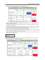
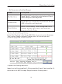
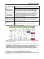
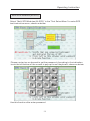
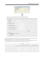
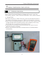
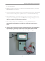
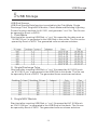
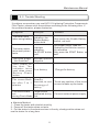
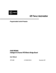
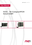
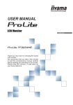
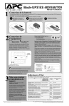
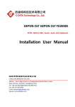
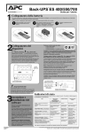
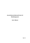
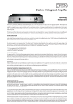
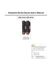
1
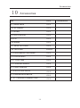
Lightning Protection Components Field Tester User's Manual KV1101 KOVI TEST EQUIPMENT CO., LTD. Document No. KV13201306201.01 Attention High voltage is generated while Lightning Protection Components Field Tester works. For your safety, please read this manual and relative document carefully before operating the tester. Be careful while operating. Keep this manual properly and put it in the place that operator easy to get. Pass this manual to the final user. 〖Design Declaration〗 !DANGER Touching the test interface or opening the case is forbidden due to the generated high voltage while the Tester works. If changing cable is necessary, please make sure no high voltage output during all the operations. !WARNING Operate the Tester properly after read this manual carefully. If problems occur during the test, please check the Tester after power off. Other Attentions: Please power off the Tester when not used to ensure the use life. l Avoid damp, rain, exposure and falling. l Storage condition for the Tester: humidity less than 75%RH, no acidity, alkalinity or causticity. l Make sure the test product and Tester are connected firmly to avoid sparking. l Preface Lightning Protection Components Field Tester User's Manual KV1101 Technical Data 1 Working Principle 2 Operating Instructions 3 Calibration Instructions 4 USB Storage 5 Test Fixture 6 Working Environment 7 Maintenance Manual 8 After-Sales Service 9 Accessories Document No: KV13201306201.01 10 General Information l Thank you for purchasing the Lightning Protection Components Field Tester of KOVI TEST l This manual mainly introduces application of the Lightning Protection Components Field Tester. l Please read this manual carefully before using the Tester. Operate the Tester properly after get enough comprehension from this manual. l Please read relative document for the software and hardware introduction. l Please pass this manual to the final user. User Instructions l No teardown when problem occurs. Only professional staff can disassemble the tester, please contact our technical department for support. l Examples in the manual and other documents are only for the comprehension and reference of the user. l Please check the standard and principle when the tester is used combined to other products. l Please check whether meet the requirements and safety issue by yourself when using this tester. l Testing is forbidden when your hands are wet or the humidity more than 75%RH. l Please follow this manual for the operation strictly . Disclaimer l All the contents in this manual have been checked carefully. Please kindly understand when the operation not accord to the manual. Please contact us on any issue about this manual. l All the contents will be checked and updated in later version. Your suggestions are welcome. l If there is any change about contents of the manual, please understand that without notice. Contact If you have any question about the use of the tester, please contact KOVI TEST. ● TEL:0755-86108776 86108775 ● FAX:0755-26039029 ● Address: 4th 4/F. Bld. No.4, Block No.2, South Honghualing Industrial Zone, Xili, Nanshan District, Shenzhen ● Zip Code:518052 Kovi Test Equipment Co., Ltd All Rights Reserved. Without express written permission, copy, transfer or use of this information and contents is prohibited. The offender shall be liable for damages. Including practical module or design patent licensing and registration of all the powers provided reserved. June , 2013 Contents Contents Preface ....................................................1 1 Technical Data ............................................2 1-1. Major Parameters. ......................................2 1- 2. Major Functions and Features. . . . . . . . . . . . . . . . . . . . . . . . . . . . . 3 2 Working Principle ........................................ .4 2-1. Schematic Diagram .....................................4 2- 2. System Diagram . . . . . . . . . . . . . . . . . . . . . . . . . . . . . . . . . . . . . . . 4 3 Operating Instructions .....................................5 3-1. Appearance Introduction ..................................5 3- 2. Operating Introduction . . . . . . . . . . . . . . . . . . . . . . . . . . . . . . . . . . 7 3-3. Operating Introduction for Transfer Software .................24 4、Calibration Instructions ....................................27 5、USB Storage ...............................................28 6、Test Fixture .......................... ........ ..............30 7、Working Environment ................. ............. .........31 8、Maintenance Manual ................... ............ .......32 8- 1. Major Accessories. . . . . . . . . . . . . . . . . . . . . . . . . . . . . . . . . . . . . . 32 8- 2. Trouble Shooting . . . . . . . . . . . . . . . . . . . . . . . . . . . . . . . . . . . . . 33 8- 3. Frequently Asked Question . . . . . . . . . . . . . . . . . . . . . . . . . . . . . 34 9、After-Sales Service .................... ............ .. .... 37 10、Accessories ............................. ......... .......38 Preface Preface Thank you for using product of KOVI TEST. This test system has specified appearance design and kinds of strict safety tests. All the parameters of this system are set to optimized value for you to get accurate test If you have any quality issue of this Tester, please contact our technical department, we will reply you with our best service. Please read this manual carefully before using this test system. 1 Technical Data 1 Technical Data 1-1.Major Parameters GDT DCBV Voltage Range 60-1800V Current Range 0.1-100µA/1-1000µA (Customized) Test Accuracy ≤±2%±1d Automatic Conversion for Positive and Negative Polarity Settable Upper and Lower Limit, qualified and unqualified Judgment. (need Test Fixture) U0.1mA MOV 60-1800V Voltage Range U1mA MOV Voltage 60-1800V Range IL Leakage Current 0-100µA 0.75U1mA Voltage Polarity U1mA≤±2%±1d Test Accuracy IL Leakage Current 0.75U1mA≤±2µA%±1d MOV Test U1mA=1mA±5µA Test Condition ILLeakage Current 0.75U1mA≤±2%±1d Automatic Conversion for Positive Voltage Polarity and Negative Polarity Settable upper and lower limit, qualified and unqualified Judgment. (Grading function is custom) Support Storage of USB Disk SPD Field Test (Meteorology) Automatic judgment and display for the category of test product Settable upper and lower limit, qualified and unqualified judgment. (Grading function is custom) Test mode M-SPD 1+1 mode, 4 MOV mode, 3+1 mode Test conversion fixture is necessary. Switch in 5 wires on triphase, One-phase, common mode or differential mode. 2 Technical Data Meteorology Data Transfer Software Support data storage function. Transfer data to PC or USB disk Support data storage function. Transfer data to PC or USB disk Transfer test data to PC. Read 3-3 operating introduction for transfer software for reference. 1-2.Major Functions and Features ● Operate Simply. One key operation finish testing. ● Support data storage of USB disk in field mode. Generated reports can be opened via Excel or WPS. ● Touch screen operation interface, convenient for man-machine communication. Controlled by 16-bit MCU. ● Support upper and lower limit setting, qualified and unqualified judgment. ● Be compatible for GDT and MOV test. ● Support intelligent judgment of Black Box components for GDT and MOV. ● Support communication with PC. Transfer real time test result to PC and generating report by dedicated software. ● Support communication with inkjet machine and laser printer for convenient production via standard modbus protocol. ● Portable and support inside battery for user operation with endurance for 6 hours. ● Support self-check and self-calibration function with multimeter. ● Support breakdown Voltage(@100V/S) of GDT(GDT, SSA and so on) and Voltage test of MOV ● Support memory, calculation, maintain, control and self-check function. 3 Working Principle 2 Working Principle 2-1.Working Principle 2-2.Working Principle PC MODBUS Man-Machine Interface Mitsubishi Protocol RS232 Control CPU( Master ) CPU( Slave ) High Voltage Generation Circuit Execution Part USB Disk Storage Dual-Polarity Output Conversion High Voltage Output Fast Test M-SPD Conversion 4 Operating Instruction 3 Operating Instructions 3 - 1. Appearance Introduction Touch Screen Battery Supply Battery Value / Charging Sign Enable Battery / Battery Check Start Test Port Test Port Right View USB Storage/Fixture Interface RS232 Data Transfer USB Storage/Fixture Interface Data Transfer Figure 2 Left View 5V5A + ON OFF External Power Power Switch External Power Figure 3 External Power 5 Operating Instruction Appearance Introduction Name Description Touch Screen Display Operation Menu Start Press this button to start test after parameters setting Battery Supply The battery supply the power when the LED lights. It will automatically cut off when extern power supplies. Battery Value/ Charging Sign Enable Battery/ Battery Check Different colors show different energy. See the tester for detail. Press this key to show the operation menu of tester when turn on the Power Switch Test Port Output test signal, connected to test touch probe. RS232 Data Transfer Connected to S232 cable, transfer data to PC. Fixture Interface Connected to test fixture USB Storage Transfer data to USB disk, only USB disk capacity less than 8GB supported. External Power Connected to AC adaptor Power Switch Turn On/Off the tester Configuration Name Description Weight About 0.96 kg Dimensions 244.5mm*152mm*47mm Aluminum Box 460mm*310mm*110mm Carton Box 525mm*400mm*165mm Package Methods Aluminum Box + Carton Box 6 Operating Instruction 3-2.Test Menu Operating Introduction Turn on power switch, press enable battery button. Enter operation menu, shown as below: Press any position of the touch screen to enter “Cautions” menu, shown as below: Select “View Version Information” to enter version information menu, shown as below. Select “Return” to return to “Cautions” menu after check version information. 7 Operating Instruction Select “Agree” in the Cautions menu to enter “Staff Password” menu, shown as below: 8 Operating Instruction Input “1111” in the soft keyboard menu, select “ENT” to the following menu: Select “Enter” in this menu to enter main menu (Test Select Menu), shown as below: 9 Operating Instruction Operation of main menu (Test Select Menu) Operation of SPD Field Test (Meteorology) • Set qualified range Select “Operation of SPD Field Test (Meteorology)” in the “Operation of main menu” to enter “Field Test SPD/Qualified Range” menu, shown as below. The Tester has been initialized before shipment, please select “Complete Setting” directly if the range is fit to the components to test. Otherwise, please set the range by yourself and see the “Qualified range setting method” for reference. 10 Operating Instruction Name Description Qualified lower limit Set qualified lower limit. Touch “qualified lower limit” and set the value between 60 and 1800 in the pop up soft keyboard. Qualified upper limit Set qualified upper limit. touch “qualified upper limit” and set the value between 60 and 1800 in the pop up soft keyboard. Complete setting Select “Complete setting” after setting done, then confirm and save the values. The values are memorized to the Tester. • Check Data Storage Instruction The Tester automatically enters “Field Test Result” menu, shown as below: Select “Data Storage Instruction” in “Field Test Result” menu to enter “Field Test Data Storage” menu, shown as below. Please read the clauses carefully. Select “Return” to return to “Field Test Result” menu. 11 Operating Instruction Field Test Instructions Make sure to return to “Field Test Result” menu, insert 4GB USB Disk to the USB interface. § Insert the crocodile clip probes to the test ports, take apart the M-SPD module and clip one of the small modules using crocodile clip. § Press the green START of the Tester to start test. Test parameters and judgment results will be displayed on the screen when test done. § When finishing test a batch of M-SPD modules, please pull out the USB Disk after the Tester power off, otherwise the storage data may be in ‘ chaos. 12 Operating Instruction § The .csv format file named by data such as “20130701.csv” is automatically generated in the USB Disk, it can be opened by both Excel and WPS. Steps of Field Test § Select “Fuzzy Test” in the “ Test Select Menu ” to enter fuzzy test (unknown name components) menu, shown as below: § Insert the crocodile clip probes to the test ports, clip the component using crocodile clip. the green START of the Tester to start test. Test parameters and judgment results will be displayed on the screen when test done. § Press Building Data (Electromagnetic Environment) § Select “Building Data (Electromagnetic Environment)” in the “Test Select Menu” to enter “Special Function Module” menu, shown as below: 13 Operating Instruction § Please contact us on demand to get the password. According to the indication, touch the left bottom of the screen to pop up the soft keyboard, shown as below: § Use this function after enter password. 14 Operating Instruction Single Discharge Tube Module § Select “Single Discharge Tube Module” in the “Test Select Menu” to enter Single Discharge Tube Module menu, shown as below: § Set Parameters (Qualified Range) Name Description Set Minimum Value Touch “Mini(V)” and set the value between 60 and 1800 in the pop up soft keyboard. Set Maximum Value Touch “Maxi(V)” and set the value between 60 and 1800 in the pop up soft keyboard. Save Setting Select “Save Setting” after setting done, then confirm and save the values. The values are memorized to the Tester. § Scalar Qualified Range Setting 15 Operating Instruction Select “Set Grading” in the single discharge tube module menu to enter discharge tube voltage range automatic grading menu, 4 kinds of qualified condition supported, shown as below: Upper Limit Setting Instruction Upper Limit of A box(qualified 1), B box(qualified 2) and C box(qualified 3) can be set in the Discharge tube voltage range automatic grading menu. ) Name Description Upper Limit of A box(qualified 1) Touch the green number of the A box (qualified 1)and set the value in the pop up soft keyboard, the value should be between the qualified minimum value in Single Discharge Tube module menu and 1800. Upper Limit of B box(qualified 2) Touch the green number of the B box (qualified 2) and set the value in the pop up soft keyboard, the value should be between Upper Limit of A box(qualified 1) and 1800. Upper Limit of C box(qualified 3) Touch the green number of the C box (qualified 3) and set the value in the pop up soft keyboard, the value should be between Upper Limit of B box(qualified 2) and 1800. Confirm Select “Save Setting” after setting done, the tester will memory the values and return to Single Discharge Tube Module menu. 16 Operating Instruction Single Discharge Tube Module Test Instructions. § w Make sure to return to “Single Discharge Tube Module” menu, insert 4GB USB Disk to the USB interface. w Insert the crocodile clip probes to the test ports, clip the Discharge Tube using crocodile clip or probe. w Press the green START of the Tester to start test. Test parameters and judgment results will be displayed on the screen when test done. w When finishing test a batch of products, please pull out the USB Disk after the Tester power off, otherwise the storage data may be lost w The .csv format file named “KV1101G.csv” is automatically generated in the USB Disk, it can be opened by both Excel and WPS. w Touch “Return” in the left bottom of the screen to return main menu (Test Select Menu) when finishing test. Single Varistor Module Select “Single MOV Module” in the “Test Select Menu” to enter Single MOV Module menu, shown as below: 17 Operating Instruction Set Parameters (Qualified Range) § Name Description Set Min Value Touch “Mini(V)” and set the value between 60 and 1800 in the pop up soft keyboard. Set Max Value Touch “Maxi(V)” and set the value between 60 and 1800 in the pop up soft keyboard. Save Setting Select “Save Setting” after setting done, then confirm and save the values. The values are memorized to the Tester. Scalar Qualified Range Setting § Select “Set Grading” in the Single MOV Module menu to enter Discharge Tube Voltage Range Automatic Grading menu, 4 kinds of qualified condition supported, shown as below: § Upper Limit Setting Instruction Upper Limit of A box(qualified 1), B box(qualified 2) and C box(qualified 3) can be set in the MOV Voltage Range Automatic Grading menu. 18 Operating Instruction Name Description Upper Limit of A box(qualified 1) Touch the green number of the A box (qualified 1) and set the value in the pop up soft keyboard, the value should be between the qualified Min Value in Single Discharge Tube Module menu and 1800. Upper Limit of B box(qualified 2) Touch the green number of the B box (qualified 2) and set the value in the pop up soft keyboard, the value should be between Upper Limit of A box (qualified 1) and 1800. Upper Limit of C box(qualified 3) Confirm Touch the green number of the C box (qualified 3) and set the value in the pop up soft keyboard, the value should be between Upper Limit of B box (qualified 2) and 1800. Select “Save Setting” after setting done, the tester will memory the values and return to Single Discharge Tube Module menu. ▪ Single Varistor Module Test Instructions w Make sure to return to “Single MOV Module” menu, insert 4GB USB Disk to the USB interface. w Insert the crocodile clip probes to the test ports, clip the MOV using crocodile clip or probe. w Press the green START of the Tester to start test. Test parameters and judgment results will be displayed on the screen when test done. w When finishing test a batch of products, please pull out the USB Disk after the Tester power off, otherwise the storage data may be lost w The .csv format file named “KV1101M.csv” is automatically generated in the USB Disk, it can be opened by both Excel and WPS. w Touch “Return” in the left bottom of the screen to return main menu (Test Select Menu) when finishing test. 19 Operating Instruction Multi SPD Modules (M-SPD) Select “Multi SPD Modules (M-SPD)” in the “Test Select Menu” to enter SPD test instruction menu, shown as below: Please contact us on demand to get the password. According to the indication, touch the left bottom of the screen to pop up the soft keyboard, shown as below: Use this function after enter password. 20 Operating Instruction Contact Us Select “Contact Us” in the “Test Select Menu” to enter Contact Us menu, shown as below: SPD Test Standard GB21431-2008 Select “SPD Test Standard (GB21431-2008)” in the “Test Select Menu” to enter Standard and Parameters menu, shown as below: 21 Operating Instruction Tester Check and Calibration (Voltage and Current) Select “Tester Check and Calibration (Voltage and Current)” in the “Test Select Menu” to enter Check and Calibration Menu and operation instruction menu, shown as below: 22 Operating Instruction 3-3.Operating Introduction for Transfer Software We have developed a data record software based on serial port communication for Lightning Protection Components Field Tester. The software is synchronized with the data of the Tester, and also able to save the data automatically. Install the software for the first time use: ♦ Click setup.exe to install the data transfer system automatically, please restart the PC after installation. ♦ Click the short cut on the desktop. 3. Main Menu 4. Configure PC ♦ Insert serial port or USB- serial port cable to the PC, shown as below: Serial Port 23 Operating Instruction USB-RS232 Cable ♦Connect the Tester and PC with serial port cable. ♦Configure COM name Right click “My Computer”, click “Management”, “Device Manager” and “Port” step by step. If the communication port is not COM1, please change it to COM1. Method: Right click “Communication Port”, click “Property”, “Ports Setting” and “Advanced” step by step, select “COM1” in the Drop-Down List and confirm. 24 Operating Instruction Open the software when finishing configuration. Press the START button on the Tester, the Tester will transfer the test data to the default path of the PC, the menu shows the data of the Tester. You can click the “auto save path select” button to save this group of data to the specified path. This group of data is saved in the relative cells. 25 Tester Calibration Instructions 4 Tester Calibration Instructions 4-1.Calibration Instructions Select “Tester Check and Calibration (Voltage and Current) ” in the Test Select Menu to pop up “Tester Check and Calibration” menu, shown as below: a、Voltage Check ♦ Shift the multimeter to “1000V” DC mode, insert the red and black probe to the relative red and black output ports. (Make sure the insertion is correct.) ♦ Select Check and Calibration Menu to start check, the Tester outputs a fixed voltage (between 530V and 600V) and the value is display on the screen. At the mean time, the multimeter shows the test value. ♦ Compare the screen display value and multimeter test value, if error is within 2% the tester is qualified. ♦ Select Finish Check to exit check, the tester return to Test Select Menu automatically. 26 Tester Calibration Instructions b、Current Check ♦ Make sure the screen return to Check and Calibration Menu, insert the 4GB USB Disk to the Tester. ♦ Insert crocodile clip probes to the red and black output ports, add a 10M resistor between the probes. (10M resistor on the Standard Module) ♦ Select Start Check, check the voltage and current value on the screen, compare current display value and 10th of the voltage display menu, if the error is within 2% the tester is qualified. ♦ Select “Output Report”, the CSV file named by KV1101T will be automatically generated in the USB Disk. Open the file by Excel or WPS. ♦ Select Finish Check to exit check, the tester return to Test Select Menu automatically. (Attention: select Finish Check after check finished, otherwise the Tester will continuously output high voltage) 27 USB Storage 5 USB Storage USB Disk Storage USB Disk Storage Data function is available in the Field Mode, Single Discharge Tube, Single MOV Module, Check Mode and Building Lightning Protect function modules for KV1101, and generate “.csv” file. The file can be opened by Excel or WPS.\ 1、Field Mode Start test after inserting USB Disk, a “.csv” file named by the date such as “20130703.csv” is generated in the USB Disk in this mode. The file can be opened by Excel or WPS. The generated cells are shown as below: 2、Single Discharge Tube Start test after inserting USB Disk, a “.csv” file named by KV1101G such as “KV1101G.csv” is generated in the USB Disk in this mode. The file can be opened by Excel or WPS. The generated forms are shown as below: 3、Single MOV Module Start test after inserting USB Disk, a “.csv” file named by KV1101M such as “KV1101M.csv” is generated in the USB Disk in this mode. The file can be opened by Excel or WPS. The generated cells are shown as below: 28 USB Storage 4、Check Mode Start test after inserting USB Disk, a “.csv” file named by KV1101T such as “KV1101T.csv” is generated in the USB Disk in this mode. The file can be opened by Excel or WPS. The generated cells are shown as below: 5、Building Lightning Protect Start test after inserting USB Disk, a “.csv” file named by the date such as “20130703C.csv” is generated in the USB Disk in this mode. The file can be opened by Excel or WPS. The generated forms are shown as below: § 6、Attention: ♦ USB Disk with capacity more than 8GB is forbidden to insert USB port. ♦ PC or mobile HDD is forbidden to be connected to USB port. ♦ The indicator of USB Disk flashes when storage done. ♦ When finishing test, please pull out the USB Disk after the Tester power off, otherwise the storage data may be lost. 29 Test Fixture 6 Test Fixture 6-1.Test Fixture § Fixture Introduction ♦ This function is customized, extra cost is necessary. ♦ The fixture uses external power supply, connect the control cable, connect tester output ports to the fixture input ports. Connect fixture output ports to SPD, press START to finish M-SPD module test. ♦ Additional introduction: the tester is available for M-SPD test, please read FAQ for reference. One SPD module for once test, operation done after M times test. 30 Working Environment 7 Working Environment Working power supply: battery inside, fit for AC220V/110V § § Environment Temperature: -10~40℃ Environment Humidify: ≤85% § Withstand Voltage: AC1.5KV 50Hz 1min § 31 Maintenance Manual 8 Maintenance Manual 8-1. Tester Accessories Accessory Type Standard Configuration Standard Configuration Name Description KV1101 0.1-100µA/1-1000µA(custom) Test Probe(2 pairs) Connect test components USB Disk Storage test result with cells AC Adaptor Charge the battery or as extern power supply Standard Module For check and calibration CD Test Software/User's Manual/ Operation Video/Chinese Standard Holder Place tester Braces For portable carry Serial Port cable Connect PC and tester, transfer test data Verification Certificate Certification Custom Item Color Page Introduce test parameters and features User's Manual Guide user to operate the tester M-SPD test fixture Support fast test M-SPD (extra cost) 32 Maintenance Manual 8-2.Trouble Shooting If problem occurs when you use KV1101 Lightning Protection Components Field Tester, please solve the problem according to the following form. If the problem remains, please contact us. Symptom Analysis Method Improper The tester halts operation: the when using battery Enable Battery button held The tester works abnormally when tests. Improper operation: the START button held Test value always “Not Qualified” Improper qualified range set. Can't power on the test. The indicator turns read when press Battery Check button. Low battery Only press the Enable Battery button, not hold Set proper range, read the Operating Introduction section for reference Only press the START Button, not hold Charge the battery The screen black Standby out after 2 to 3 function, to save the energy of minutes battery Touch any position of the touch screen to wake up the tester Large current The screen black generated during out during Check Mode test Connect external power supply ♦ Maintain Method 1、Clean the tester with alcohol monthly. 2、Power off the tester when no tests. 3、Put the tester to the aluminum box in the dry, shady position when not use the tester for a long time 33 Maintenance Manual 8-3.FAQ Q&A: 1. Can the power on M-SPD module be tested with KV1101? A: No. KV1101 is only for power off Lightning Protection Components Test (GDT MOV and M-SPD), not power on. Because there is a voltage between the 2 ports of the power on M-SPD module and so is the KV1101, if the M-SPD module and KV1101 are connected directly, accident occurs. The tester will be burned out, and the power supply circuit that M-SPD protects may be burned out too. 2.Can M-SPD module be tested without test fixture with KV1101? A: Yes, but only one sub module for one test. Here are two test methods: .In SPD Field Test (Meteorology) mode, take apart the sub modules from the MSPD, clip the sub module with crocodile clip probes, test them one by one. ② .In SPD Field Test (Meteorology) mode, connect the M-SPD short out port and other port of the M-SPD module with pointer probes, test the sub modules one by one. 3. Is the test fixture contained in the Standard Configuration? If not, free or not? A: Not contained in the Standard Configuration, it is customized. It's not free. 4. Can the Enable Battery button be held for a long time after KV1101 power on? A: No. The Enable Battery button is only used to activate the battery circuit when the tester uses the battery supply, release the button after the tester power on. Otherwise, the tester may halt or occur other problems. 5.If KV1101 continuously works for a long time (4 hours), will the battery inside explode? A: The battery becomes heated when the tester continuously works, but won't explode. KV1101 uses polymer battery. When the tester overloads, the battery may be declared worthless, but won't explode. 6. Can KV1101 be used in thunderstorm day outdoors? A: No. KV1101 is not moisture proof, operation in this condition will cause danger to the operators. 7、Can KV1101 store data? How does it work? A: Yes, via USB Disk. The files generated in the USB Disk can be opened by Excel and WPS. 34 Maintenance Manual 8、Can KV1101 transfer real time data to PC? A: Yes. Install the specified software we developed, connect the tester and PC via serial port cable, the test data can be transferred to PC and generate the forms. 9、Can KV1101 be connected to the PC via USB cable? A: No. USB port of KV1101is only for USB Disk, its connection to PC will cause short out and burn out the tester or the PC. 10.Can USB Disk pulled out when power on? A: No. The correct operation of USB Disk is shown as below: insert the USB Disk when entering Test Menu after power on (caution: insertion during test is forbidden); pull out the USB Disk after power off. Otherwise, it may cause the stored data in chaos, even damage the USB Disk. 11、How much the capacity of USB Disk can be supported by KV1101? A: KV1101 Standard Configuration USB Disk is with capacity of 4GB, it can support 32GB on maximum, but don't support mobile HDD. But the data storage becomes not stable when the capacity of USB Disk goes up. Standard Configuration USB Disk is recommended. 12.How many sub types do KV1101 have? What's the difference among them? A:KV1101 has 3 versions: KV1101A, KV1101B and KV1101C. KV1101A is mainly used for the Lightning Protection Components manufacture, KV1101B for Lightning Protection Components dealer and KV1101C for Meteorology, Operator and Engineering Company. 13. Are there some standards for KV1101? A:KV1101 has following reference stand: ①GB21431-2008 <Technical specifications for inspection of lightning protection system in building> ②IEC61643.311 Specification for gas discharge tubes (GDT) ③IEC61643.331 Specification for metal oxide varistors(MOV) ④IEC61643.321, IEC61643.341 and so on. 14.Which fields is KV1101 used in? A:KV1101 is mainly used in following fields: ① Lightning Protection Components (MOV, GDT and SPD module) manufacture. ② Operator (Meteorology, Electricity, Communication, Railway, Petrifaction and Public Security). ③ Lightning Protection Components(MOV, GDT and SPD module) dealer, agent and Lightning Protection Project Construction Organization. 35 Maintenance Manual 15.Are there other passwords beside “1111” for KV1101? A:Yes, there are. The functions based on “1111” are used to meet general customers' demands. Other passwords support advanced functions, please contact us for details. 16.Can you introduce the After-Sales Service of KV1101? A:The warranty period of KV1101 is 1 year, maintain period is throughout the tester's life. The customer should bear the cost after warranty period. 17.Does KV1101 have Check and Calibration function? How to operate? A:Yes, it has. Please read Check and Calibration Instructions or Check and Calibration Operation Manual for detail. 18.Does KV1101 have stand-by function? A:KV1101 will go to stand-by status when no operation lasts 3 minutes. The screen black out, press any position of the touch screen to wake up the tester. 19.What are the regular working voltage and current range for KV1101? A: Regular output voltage range: 60V-1800V. Current range: 0.1μA-1000μA. 20. What are the advantages of KV1101 compared with other products on the market? A: 1. Operate Simply. One Key Test. 2. Touch Screen Operation Interface, Convenient for Man-Machine Communication 3. Compatible for GDT and MOV Test. 4. Support Intelligent Judgment of Black Box Components for GDT and MOV Test. 5. Portable and Support inside Battery for User Operation with endurance for 6 hours with. 6. Support Self-Check and Self-Calibration Function with Multimeter. 36 After-Sales Service 9 After- Sales Service One year free warranty service is provided since Lightning Protection Components Field Tester (KV1101) purchased, warranty date starts from the date of purchase invoice of the product. Under normal use, non-human damage, buyers can bring the warranty card and invoice for the repair service. Have one of the following conditions; do not belong to the free warranty coverage The fault caused by operation not according to the instructions on the requirements of the User's Manual. The fault caused by artificial drop or impact. The fault caused by unauthorized breaking down or installation. The fault caused by accident, misoperation , try out or intentional damage. Out of warranty period KOVI TEST has the right to modify the tester without notification. All content of this manual have been carefully checked, KOVI TEST reserves the right of final interpretation for printing error or the misunderstanding of the contents. Customer Feedback Thank you for your use of KOVI products, only sincerely to thanks! In order to provide more timely repair, consulting and other service for you, help you to encounter problems in the process of using, please fill out the feedback receipt and send it to our company, to establish user service files. 37 Accessories 10 Accessories Item 1PCS 10-1.power cable 1PCS 10-2.AC adaptor 1PCS 10-3 Holder 1PCS 10-4 4GB USB Disk 1PCS 10-5 CD 1PCS 10-6 Braces 1PCS 10-7 Serial Port Cable 1PCS 10-8 Test Probe 2PAIRS 10-9 Verification Certificate 1PCS 10-10 Certification 1PCS 10-11 Color Page 1PCS 10-12 Standard Module 1PCS 10-13 User's Manual 1PCS 10-14 M-SPD test fixture 1PCS 10-15 Maintenance Manual 1PCS 10- 16、Customer Feedback Card 1PCS 38 Confirmation Accessories KOVI TEST Productions Warranty Card Production Name: Production Type: Date of Production: Production S/N: Purchase Date: Purchaser Name: Address: Telephone: Agent Name: Address: Tel: 39 Accessories KOVI TEST Productions Feedback Card Production Name: Production Type: Date of Production: Production S/N Purchase Date: Purchaser Name: Address: Tel: Agent Name: Address: Telephone: 40 Accessories Customer Comments Customer Signature: Please fill in the card when purchasing KV1101, send the card with agent's seal to KOVI TEST Customer Service Department in 30 days. KOVI TEST will establish user service files and offer track service for you. Please send the Feedback Card to KOVI TEST on following address: Address: 4th 4/F. Bld. No.4, Block No.2, South Honghualing Industrial Zone, Xili, Nanshan District, Shenzhen E-mail: [email protected] 41 Accessories Customer Comments Maintenance Date Maintenance Condition Responsible Person Maintenance Date Maintenance Condition Responsible Person 42 深 圳 市 科 威 电 子 测 试有限公司 KOVI TEST EQUIPMENT CO.,LTD. 深 圳 市南山 区 西 丽镇红 4th 4/F. Bld. No.4, Block No.2, South Honghualing 花 岭 工业南 区2区4栋4楼 Industrial Zone, Xili, Nanshan District, Shenzhen 电 话 :075 5 - 8 6 1 0 8 776 TEL:0755-8610 8776 传 真 :075 5 - 2 6 0 3 9029 Fax:0755-2603 9029 网 址 :www . k o v i t e s t.com Homepage:www.kovitest.com