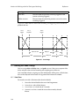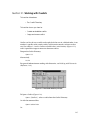
1
Wholehog III
User Manual
Version 1.2
Wholehog III: User Manual
High End Systems, Inc.
US and the Americas, Sales:
High End Systems, Inc.
2217 West Braker Lane
Austin, TX 78758
USA
Voice: +1 (512) 836 2242
Fax: +1 (512) 837 5290
US and the Americas, Customer Service:
High End Systems, Inc.
2217 West Braker Lane
Austin, TX 78758
USA
Voice: +1 (800) 890 8989
24-hour fax: +1 (512) 834 9195
24-hour voice mail: +1 (512) 837 3063 or +1 (800) 890 8989
U.S., New York:
High End Systems, Inc. New York
311 W. 43rd Street, Ste 400
New York, NY 10036
USA
Voice: +1 (212) 957 6840
Fax: +1 (212) 957 4466
U.S., Los Angeles:
High End Systems, Inc.
8200 Haskell Avenue
Van Nuys, CA 91406
USA
Voice: +1 (818) 947 0550
Fax: +1 (818) 908 8975
Europe:
High End Systems Europe Ltd.
53 Northfield Road
London, W13 9SY
UK
Voice: +44 (0) 20 8579 5665
Fax: +44 (0) 20 8579 8469
Germany voice: +49 (5331) 9925 91
Germany fax: +49 (5331) 9925 92
Singapore:
High End Systems Singapore Pte. Ltd.
1 Tannery Road 06-05
Cencon 1
Singapore, 1334
Voice: +65 742 8266
Fax: +65 743 9322
Internet:
Email: [email protected],
Web: www.flyingpig.com
Copyright
© High End Systems, Inc. 2002, All Rights Reserved.
Changes
Information and specifications in this document are subject to change without notice. High End Systems, Inc.
assumes no responsibility or liability for any errors or inaccuracies that may appear in this manual.
Trademarks
Trademarks used in this text: High End Systems, Wholehog II, and Wholehog III, are registered trademarks;
the High End Systems globe logo and the Hog logo are trademarks of High End Systems, Inc. or High End
Systems Europe Ltd.
Other trademarks and trade names may be used in this document to refer to either the entities claiming the
marks and names or their products. High End Systems disclaims any proprietary interest in trademarks and
trade names owned by others.
FCC Information
This equipment has been tested and found to comply with the limits for a Class A digital device, pursuant to
part 15 of the FCC rules. These limits are designed to provide reasonable protection against harmful
interference when the equipment is operated in a commercial environment. This equipment generates, uses,
and can radiate radio frequency energy and, if not installed and used in accordance with the instruction
manual, may cause harmful interference to radio communications. Operation of this equipment in a
residential area is likely to cause harmful interference, in which case the user will be required to correct the
interference at his own expense.
Product Modification Warning
High End Systems products are designed and manufactured to meet the requirements of United States and
International safety regulations. Modifications to the product could affect safety and render the product
non-compliant to relevant safety standards.
Mise En Garde Contre La Modification Du Produit
Les produits High End Systems sont conçus et fabriqués conformément aux exigences des règlements
internationaux de sécurité. Toute modification du produit peut entraîner sa non conformité aux normes de
sécurité en vigueur.
Produktmodifikationswarnung
Design und Herstellung von High End Systems entsprechen den Anforderungen der U.S. Amerikanischen
und internationalen Sicherheitsvorschriften. Abänderungen dieses Produktes können dessen Sicherheit
beeinträchtigen und unter Umständen gegen die diesbezüglichen Sicherheitsnormen verstoßen.
Avvertenza Sulla Modifica Del Prodotto
I prodotti di High End Systems sono stati progettati e fabbricati per soddisfare i requisiti delle normative di
sicurezza statunitensi ed internazionali. Qualsiasi modifica al prodotto potrebbe pregiudicare la sicurezza e
rendere il prodotto non conforme agli standard di sicurezza pertinenti.
Advertencia De Modificación Del Producto
Los productos de High End Systems están diseñados y fabricados para cumplir los requisitos de las
reglamentaciones de seguridad de los Estados Unidos e internacionales. Las modificaciones al producto
podrían afectar la seguridad y dejar al producto fuera de conformidad con las normas de seguridad
relevantes.
Important Safety Information
Instructions pertaining to continued protection against fire, electric shock, and injury to persons are found in
Safety Information (Appendices, 30.1).
Please read all instructions prior to assembling, mounting, and operating this equipment.
Important: Informations De Sécurité
Les instructions se rapportant à la protection permanente contre les incendies, l’électrocution et aux
blessures corporelles se trouvent dans Importantes Informations Sur La Sécurité (Appendices, Section 30.2).
Veuillez lire toutes les instructions avant d’assembler, de monter ou d’utiliser cet équipement.
Wichtige Sicherheitshinweise
Sicherheitsanleitungen zum Schutz gegen Feuer, elektrischen Schlag und Verletzung von Personen finden Sie
in Wichtige Hinweise Für Ihre Sicherheit (Appendices, Abschnitt 30.3).
Vor der Montage, dem Zusammenbau und der Intbetriebnahme dieses Geräts alle Anleitungen sorgfältig
durchlesen.
Informazioni Importanti Di Sicurezza
Le istruzioni sulla protezione da incendi, folgorazione e infortuni sono contenute nell Importanti
Informazioni Di Sicurezza (Appendices, Sezione 30.5).
Si prega di leggere tutte le istruzioni prima di assemblare, montare e azionare l’apparecchiatura.
Informacion Importante De Seguridad
En el Información Importante De Seguridad (Appendices, Sección 30.4) se encuentran instrucciones sobre
protección continua contra incendios, descarga eléctrica y lesiones personales.
Lea, por favor, todas las instrucciones antes del ensamblaje, montaje y operación de este equipo.
Warranty Information
Limited Warranty: Unless otherwise stated, your product is covered by a one year parts and labour limited
warranty. It is the owner’s responsibility to furnish receipts or invoices for verification of purchase, date, and
dealer or distributor. If purchase date cannot be provided, date of manufacture will be used to determine
warranty period.
Returning an Item Under Warranty for Repair: It is necessary to obtain a Return Material Authorization
(RMA) number from your dealer or point of purchase BEFORE any units are returned for repair. The
manufacturer will make the final determination as to whether or not the unit is covered by warranty.
Any Product unit or parts returned to High End Systems must be packaged in a suitable manner to ensure the
protection of such Product unit or parts, and such package shall be clearly and prominently marked to
indicate that the package contains returned Product units or parts and with an RMA number. Accompany all
returned Product units or parts with a written explanation of the alleged problem or malfunction. Ship
returned Product units or parts to: 53 Northfield Road, London, W13 9SY, UK.
Note: Freight Damage Claims are invalid for fixtures shipped in non-factory boxes and packing materials.
Freight: All shipping will be paid by the purchaser. Under no circumstances will freight collect shipments be
accepted.
REPAIR OR REPLACEMENT AS PROVIDED FOR UNDER THIS WARRANTY IS THE EXCLUSIVE REMEDY OF
THE CONSUMER. HIGH END SYSTEMS, INC. MAKES NO WARRANTIES, EXPRESS OR IMPLIED, WITH
RESPECT TO ANY PRODUCT, AND HIGH END SPECIFICALLY DISCLAIMS ANY WARRANTY OF
MERCHANTABILITY OR FITNESS FOR A PARTICULAR PURPOSE. HIGH END SHALL NOT BE LIABLE FOR
ANY INDIRECT, INCIDENTAL OR CONSEQUENTIAL DAMAGE, INCLUDING LOST PROFITS, SUSTAINED
OR INCURRED IN CONNECTION WITH ANY PRODUCT OR CAUSED BY PRODUCT DEFECTS OR THE
PARTIAL OR TOTAL FAILURE OF ANY PRODUCT REGARDLESS OF THE FORM OF ACTION, WHETHER IN
CONTRACT, TORT (INCLUDING NEGLIGENCE), STRICT LIABILITY OR OTHERWISE, AND WHETHER OR
NOT SUCH DAMAGE WAS FORESEEN OR UNFORESEEN.
Warranty is void if the product is misused, damaged, modified in any way, or for unauthorized repairs or
parts. This warranty gives you specific legal rights, and you may also have other rights which vary from state
to state.
Revision History
Revision 0.8 beta 1 1st May 2002
Revision 0.9 beta 4 24th June 2002
Revision 1.0
21st July 2002
Revision 1.1
January 2003
Revision 1.2
May 2003
Declaration of Conformity
According to ISO/IEC Guide 22 and EN45104
Manufacturer’s name: Flying Pig Systems (High End Systems Europe Ltd.)
Distributor’s name:
High End Systems Europe Ltd.
Distributor’s address:
53 Northfield Road, London, W13 9SY
Declares that the product:
Product Name:
Wholehog III
Product Number:
All
Product Options:
All
Conforms to the following EEC directives:
73/23/EEC, as amended by 93/68/EEC
89/336/EEC, as amended by 92/31/EEC and 93/68/EEC
Equipment referred to in this declaration of conformity was first manufactured in
compliance with the following standards in 2002:
Safety:
EN60950:2000
EMC:
EN55103-1:1996 (E2)
EN55103-2:1996 (E2)
I, the undersigned, hereby declare that the equipment specified above conforms to
the above Directives and Standards.
Richard Bunn, Compliance Engineer
30 May 2002
8
Table of Contents
Introduction.................................................................................... xv
1: Getting Started ..................................................................... 1
1.1 Where to Start .............................................................. 1
1.2 Key................................................................................. 1
2: Users New to Moving Light Consoles.................................. 3
2.1 The User Interface........................................................ 3
2.2 Referring to Fixtures ..................................................... 3
2.3 Palettes ......................................................................... 4
2.4 Tracking ........................................................................ 4
2.5 Multiple Playbacks and Cuelists ................................ 6
2.6 HTP and LTP .................................................................. 6
2.7 Individual Times for Each Parameter......................... 7
3: Wholehog II Users................................................................. 9
3.1 Networking ................................................................... 9
3.2 The Front Panel ............................................................ 9
3.3 New Windows ............................................................ 10
3.4 New Playback Features............................................ 10
3.5 The Effects Engine...................................................... 11
3.6 Abstraction................................................................. 11
3.7 Colour Matching ....................................................... 12
3.8 New and Streamlined Functions.............................. 14
Tutorial ............................................................................................ 15
4: Quick and Dirty: Create a Show in Ten Steps .................. 17
Step 1: Connecting the Mains ....................................... 17
Step 2: Connecting the DMX Processor........................ 17
Step 3: Starting the Console........................................... 17
Step 4: Starting a New Show .......................................... 17
Step 5: Adding the Fixtures............................................. 17
Step 6: Patching the Fixtures .......................................... 17
Step 7: Setting Parameters ............................................. 18
Step 8: Recording the Cue............................................. 18
Step 9: Playing Back the Cue ........................................ 18
Step 10: Changing the Cue Time .................................. 19
5: Tutorial Overview................................................................ 21
5.1 Introduction................................................................ 21
5.2 WYSIWYG Visualization.............................................. 21
6: Setting Up the Console ...................................................... 23
6.1 Connecting and Turning On the System ................ 23
6.2 Calibrating Screens and Setting Up Peripherals .... 24
6.3 Launching A New Show ........................................... 26
6.4 Find Out More ............................................................ 27
6.5 If You Get Stuck ......................................................... 28
7: Setting Up the Show ........................................................... 29
ix
7.1 Adding the Fixtures.................................................... 29
7.2 Patching the Fixtures ................................................. 30
7.3 Setting User Numbers ................................................ 32
7.4 Creating Palettes and Groups ................................. 32
7.5 Find Out More ............................................................ 33
7.6 If You Get Stuck ......................................................... 33
8: Setting Fixtures, and Creating Groups and Palettes ....... 35
8.1 Selecting Fixtures ....................................................... 35
8.2 Creating Groups........................................................ 36
8.3 Setting Parameters .................................................... 38
8.4 Creating Palettes....................................................... 40
8.5 Find Out More ............................................................ 41
8.6 If You Get Stuck ......................................................... 42
9: Recording Cues and Times ............................................... 43
9.1 Building the Look ....................................................... 43
9.2 Recording a Cue....................................................... 43
9.3 Setting Timings ........................................................... 43
9.4 Find Out More ............................................................ 44
9.5 If You Get Stuck ......................................................... 44
10: Playback ........................................................................... 45
10.1 Find Out More .......................................................... 45
10.2 If You Get Stuck ....................................................... 45
11: Saving and Shutting Down............................................... 47
11.1 Saving the Show ...................................................... 47
11.2 Backing Up ............................................................... 47
11.3 Shutting Down.......................................................... 48
11.4 Find Out More .......................................................... 48
11.5 If You Get Stuck ....................................................... 48
Reference....................................................................................... 49
12: Setting Up the System ...................................................... 51
12.1 Setting Up the Console ........................................... 51
12.2 Setting Up the Network........................................... 56
12.3 Working with Network Processors .......................... 59
13: Using the Console ............................................................ 63
13.1 Basic Concepts........................................................ 63
13.2 Working with Windows ............................................ 65
13.3 Working with Spreadsheets .................................... 70
13.4 Working with Directories ......................................... 71
13.5 Working with Editors ................................................ 73
13.6 Using the Command Line....................................... 75
13.7 Starting Up and Shutting Down ............................. 77
13.8 Managing Show Data ............................................ 78
13.9 Audio Playback from CD........................................ 80
14: Adding and Configuring Fixtures.................................... 83
14.1 Adding a Fixture to the Show................................. 83
x
14.2 Removing a Fixture from the Show........................ 84
14.3 Patching Fixtures...................................................... 84
14.4 Configuring Fixtures ................................................. 87
15: Selecting Fixtures and Modifying Parameters ............... 95
15.1 Selecting Fixtures ..................................................... 96
15.2 The Selection Order................................................. 98
15.3 Modifying Parameters............................................. 98
15.4 Fanning ................................................................... 105
15.5 Setting Timings ....................................................... 107
15.6 Removing Values ................................................... 109
15.7 Linked Parameters................................................. 110
16: Working with Groups ...................................................... 113
16.1 Recording a Group ............................................... 113
16.2 Using Groups in Programming.............................. 115
16.3 Deleting Groups..................................................... 115
16.4 Copying and Moving Groups .............................. 115
16.5 Editing Group Contents ........................................ 115
17: Working with Palettes ..................................................... 117
17.1 Recording a Palette.............................................. 118
17.2 Record Options...................................................... 119
17.3 Using Palettes in Programming ............................ 120
17.4 Deleting Palettes ................................................... 121
17.5 Copying and Moving Palettes ............................. 121
17.6 Editing Palette Contents....................................... 121
17.7 Palette Types .......................................................... 122
18: Advanced Programming............................................... 125
18.1 Selecting from What is Onstage .......................... 125
18.2 Bringing Values Into the Programmer.................. 125
18.3 Highlight and Lowlight .......................................... 126
18.4 Blind......................................................................... 127
18.5 Parking .................................................................... 127
19: Working with Cues.......................................................... 129
19.1 Recording a Cue................................................... 129
19.2 Record Options...................................................... 131
19.3 Deleting Cues ........................................................ 131
19.4 Copying and Moving Cues .................................. 131
19.5 Editing Cue Contents............................................ 132
19.6 Working with Tracking ........................................... 133
20: Working with Cue Timing and Ordering ....................... 137
20.1 Working with Fade Timings ................................... 138
20.2 Working with Cue Triggers .................................... 141
20.3 Working with Loops and Links .............................. 142
20.4 Triggering One Cue from Another....................... 144
21: Working with Cuelists ..................................................... 147
21.1 Creating Cuelists ................................................... 148
21.2 Naming Cuelists ..................................................... 148
xi
21.3 Deleting Cuelists .................................................... 148
21.4 Copying and Moving Cuelists.............................. 149
22: Working with Scenes ...................................................... 151
22.1 Recording a Scene ............................................... 151
22.2 Deleting Scenes..................................................... 152
22.3 Copying and Moving Scenes .............................. 153
22.4 Editing Scene Contents ........................................ 153
22.5 Scene Timing.......................................................... 153
23: Working with Effects ....................................................... 155
23.1 The Effects Engine.................................................. 155
23.2 Types of Effect ........................................................ 156
23.3 Effect Attributes ..................................................... 157
23.4 Applying an Effect................................................. 158
23.5 Recording an Effect Palette................................. 158
24: Cuelist Playback ............................................................ 161
24.1 Playback Attached to a Physical Master ........... 161
24.2 Playback with a Virtual Master ............................ 163
24.3 Overrides ................................................................ 164
24.4 Playback Options .................................................. 164
24.5 Displaying Cuelists ................................................. 166
25: Scene Playback ............................................................. 169
25.1 Playback Attached to a Physical Master ........... 169
25.2 Playback with a Virtual Master ............................ 169
25.3 Playback Options .................................................. 170
26: Working with Pages ........................................................ 173
26.1 Creating a New Page........................................... 173
26.2 Changing Page ..................................................... 173
26.3 Modifying Pages.................................................... 175
26.4 Copying and Moving Pages ................................ 175
26.5 Template Page ...................................................... 176
27: Working with Playback Controls ................................... 177
27.1 Grand Master......................................................... 177
27.2 Configuring Playback Controls ............................ 177
28: Working with MIDI and Timecode................................. 179
28.1 Triggering Cues With MIDI..................................... 179
28.2 Bringing Timecode into the Console................... 179
28.3 Triggering Cues from Timecode .......................... 182
28.4 Viewing Timecode ................................................ 182
28.5 Simulating Timecode ............................................ 183
Appendices ................................................................................. 185
29: Technical Specifications................................................ 187
29.1 Wholehog III Console ............................................ 187
29.2 DMX Processor ....................................................... 188
29.3 MIDI/Timecode Processor..................................... 188
29.4 Rackmount Control Unit ....................................... 189
xii
30: Safety Information .......................................................... 191
30.1 Safety Information ................................................. 191
30.2 Importantes Informations Sur La Sécurité ........... 191
30.3 Wichtige Hinweise Für Ihre Sicherheit.................. 192
30.4 Información Importante De Seguridad .............. 192
30.5 Importanti Informazioni Di Sicurezza ................... 193
30.6 Vigtig Sikkerhedsinformation ................................ 194
31: Upgrading and Care of the Console............................ 195
31.1 Updating Software ................................................ 195
31.2 Care of Touch Screens.......................................... 196
31.3 Front Panel Care.................................................... 197
32: Servicing ......................................................................... 199
32.1 Replacing Touch Panels ....................................... 199
32.2 Replacing Faders .................................................. 199
32.3 Cleaning Faders .................................................... 200
32.4 Replacing the Trackball........................................ 200
33: Getting Help.................................................................... 203
33.1 Troubleshooting ..................................................... 203
33.2 Reporting Problems ............................................... 204
Glossary ....................................................................................... 207
Index............................................................................................. 219
xiii
xiv
Introduction
Table of Contents
Getting Started ................................................................................ 1
Users New to Moving Light Consoles ............................................. 3
Wholehog II Users ............................................................................ 9
Section 1: Getting Started
The Wholehog III has been designed to be as easy to use as possible. However, it is
also designed to control big, complex lighting rigs (as well as small, simple ones)
and so at times operating the console is going to get complex too.
This manual has been written to help you become a proficient programmer with
the Wholehog III, wherever you are starting from and whatever kind of lighting you
do.
1.1 Where to Start
If you want to get going straight away, go to Quick and Dirty: Create a Show in Ten
Steps (Tutorial, Section 4). Otherwise, we recommend that you read one of the two
sections designed to help you make the transition to the Wholehog III, according to
your previous experience with consoles:
Users New to Moving Light Consoles (Introduction, Section 2)
Wholehog II Users (Introduction, Section 3)
If you haven’t used a Wholehog console before but are experienced with other
moving light consoles, you may still find the section Users New to Moving Light
Consoles (Introduction, Section 2) useful.
After that, you can either follow the Tutorial or simply start using the console and
use the Reference as needed.
1.2 Key
The following conventions are used in the text of the manual:
Pan and Tilt
(Reference, 15.3.2)
A cross reference to another part of the manual. In
electronic versions of the manual (HTML and PDF) these
references are clickable hyperlinks.
fixture
A reference to a term in the Glossary. In electronic
versions of the manual (HTML and PDF) these references
are clickable hyperlinks.
Enter
A name of an interface element such as a button, key or
window.
[Studio Color]
A button that has a label that is specific to the show,
created by the console or the user. The brackets indicate
a label that will vary depending on your particular show.
10 + 12
Text or other information that you should enter using the
numeric keypad or the on-screen or external keyboard.
[password]
A description of information that you should enter that is
not the literal text.
1
Section 1: Getting Started
Introduction
Record, Enter
Buttons or keys separated by commas show that the
keystrokes are sequential. In this case, press the Record
key, then the Enter key.
Open + Fixture
Buttons or keys followed by + are held down while the
second key is pressed. In this example, hold down the
Open key and press Fixture.
Setup −→ Fixture −→
Fixtures window
A series of operations that navigate through windows and
toolbars.
In the manual the word ‘key’ is used to indicate a hardware button on the
Wholehog III’s front panel. For example: ‘press the Enter key’. The word ‘button’
refers to ‘virtual’ buttons that can be pressed on the touch screens or clicked on
with the trackball or mouse.
You will also find important or useful information highlighted:
!
»
Caution
A caution, which has information about hazards to equipment or
personnel.
Important
An important note, usually alerting you to situations where you might
lose some of your show’s data. There are very few of these.
Tip
A tip, to help you be more productive in your programming.
2
Section 2: Users New to Moving Light Consoles
If your previous experience with lighting consoles has been mainly with ‘theatre’
desks (Strand, ETC, etc.) then this section will introduce you to some fundamental
differences that you will find with the Wholehog III.
When you have finished this section, you may also find the sections on Abstraction
(Introduction, 3.6) and Colour Matching (Introduction, 3.7) useful.
2.1 The User Interface
Most ‘theatre’ desks use a command line to control them. This means that you
enter instructions using a keypad, in the form channel 36 at 50. Information shown
on displays is limited to pure text, and only one screen layout can be displayed on
one display at a time.
The Wholehog III is rather different. It has been designed on the principle that you
should be able to see any information about your programmed show at any time,
and that you should be able to change that information directly if you wish to. In
addition to a conventional command line, the Wholehog III uses a graphical user
interface similar to those found on personal computers. Combined with the touch
screens, this interface gives a very powerful alternative way of working. You can
arrange multiple windows as you want them on the screens, in order to display
whatever information you need. You do not have to write down (or remember) as
much, because the window that shows you, say, groups that you have programmed
also allows you to select those groups simply by touching them. Any object, such as
a cue, a group or a fixture, can be named as you wish for easy identification.
The advantages of a graphical user interface are far-reaching, and will become fully
apparent as you get more familiar with the Wholehog III. For more information,
see The Graphical User Interface (Reference, 13.1.1) and Working with Windows
(Reference, 13.2).
2.2 Referring to Fixtures
Lighting consoles that have been primarily designed to work with ‘conventional’
fixtures that have only one parameter (intensity) generally refer to fixtures by
number. These ‘channel’ numbers usually run consecutively in a single sequence,
say from 1 to 200. This can be a problem with fixtures such as moving lights that
have multiple parameters and so require multiple channels to control, causing the
numbering sequence to no longer relate to separate fixtures.
The Wholehog III treats a fixture as a single entity, no matter how many or few
parameters it has. By default, each type of fixture has its own numbering range, so
that you would refer to ‘Studio Spot 6’ and ‘Cyberlight 12’. Fixtures can be
numbered in any way that you prefer, however. For more information, see
Modifying the User Number (Reference, 14.4.1).
The Wholehog III treats conventional lights, consisting of a luminaire controlled by
a dimmer, as a special kind of fixture known as a ‘desk channel’.
3
Section 2: Users New to Moving Light Consoles
Introduction
2.3 Palettes
The complexity of modern lighting rigs, especially with the widespread use of
moving lights, means that programming can be very time consuming. Palettes help
to simplify the process by allowing pre-defined lighting ‘elements’ to be created
and then used as required. A great advantage of palettes over the equivalent ‘group’
type features found on many consoles is that they update automatically. If the
palette is changed, then all cues that have been recorded using the palette are also
changed. This is especially useful if, for example, the position of a piece of set on
stage is moved, and moving lights have been programmed to hit it. The palette can
be updated once to accommodate the change, rather than in every cue. For more
information, see Working with Palettes (Reference, Section 17).
2.4 Tracking
Tracking is quite a difficult concept at first, but it is a very important one. When a
sequence of cues is programmed, the lighting console can store the information in
one of two ways: either it records the settings for all the lights on stage in every cue,
or it just records the changes from one cue to the next. The second method is
called tracking. For example, consider the following sequence of three cues:
Channel:
1
2
3
4
Cue 1
100
0
50
50
Cue 2
50
0
100
50
Cue 3
50
100
100
50
With a non-tracking console, the cues would be recorded with the channel levels as
shown. With a tracking console, however, the recorded information would be:
Channel:
1
2
3
4
Cue 1
100
0
50
50
Cue 2
50
Cue 3
100
100
If the channel level has not changed from the previous cue, then no level is
recorded for that channel.
So, during playback there are two types of fixture parameter value on stage:
4
•
Hard Values: values programmed into the current cue. Hard
values are sometimes known as hard commands.
•
Tracked Values: those values set in previous cues but that have
not yet been changed again or removed from the output. These
values are said to have ‘tracked through’ from a previous cue in
which they were Hard Values.
Introduction
Section 2: Users New to Moving Light Consoles
2.4.1 Tracking Through Changes
One advantage of tracking is that changes can be ‘tracked through’ a series of cues.
For example, if after programming a scene you decide that the level on the
cyclorama floods is too low, you can change the level through the whole scene just
by changing the first cue. If the cyc floods don’t change level in the cues during the
rest of the scene, those cues will contain no levels for the cyc channels, and the
modified levels will track through until a cue when the levels do change.
While this can help speed up the modification of cues, you may not always want
changes to track through. Typically at the start of a new section of the performance
the lighting look will essentially ‘start from scratch’, and you want to prevent
changes tracking through from the previous section. To do this you can create a
blocking cue which contains hard values for all parameters that have values at that
point in the cuelist, regardless of whether the values have tracked through from
previous cues. This then acts as an end-stop, preventing changes from tracking
past the blocking cue.
See Blocking Cues (Reference, 19.6.2).
2.4.2 Simultaneous Cues
Another advantage of tracking is that multiple cues can be run simultaneously.
Imagine a play where the sun is setting outside the window, and characters turn on
various lights in the room as the natural light fades. With a non-tracking console
this would cause problems: what would you programme in the cues that turn the
room lights on? If you recorded the full state, you wouldn’t know what level to set
the sunset fixtures at, as during playback they will have faded down to some
indeterminate level during the action of the scene. The cue to turn the room light
on would be a snap cue, and the result would be a snap change in the sunset as
well - not very realistic!
A tracking console allows you to programme just the room lights into the cue, so
that the cue won’t interfere with the sunset fixtures, which will proceed with their
long fade undisturbed.
Similarly, tracking allows multiple chases to be run at the same time without them
conflicting, so that you can run a colour chase and a (different) intensity chase on
the same fixtures. This is possible because only the colour parameters of the fixture
are recorded in the colour chase, and only the intensity parameters in the intensity
chase.
2.4.3 Maintain State
One disadvantage found with some tracking consoles occurs when you play back
cues out of sequence. Typically this will happen during rehearsals when you want
to go back over a section of the show, but it can happen during performance if the
performers miss out a bit, for example.
If you jump from cue 3 to cue 8, the look on stage will not be correct, because cue 8
only contains the information needed to create the state of cue 8 if you are starting
from cue 7. Start from cue 3, and the look on stage will be wrong.
5
Section 2: Users New to Moving Light Consoles
Introduction
The Wholehog III avoids this by Maintaining State. This means that whenever you
run a cue, the console ensures that what you get on stage is what you would have
got if you had run through the cuelist up to that point, regardless of where you have
actually come from in the cue list.
Most of the time, maintaining state means that the console does what you would
expect and want. Occasionally, you may wish to turn this feature off: see Tracking
Through Loops (Reference, 20.3.3).
2.5 Multiple Playbacks and Cuelists
Most ‘theatre’ consoles only use a single cue list. The Wholehog III allows multiple
cue lists, each with their own numbering sequence. These can be replayed either at
the same time on multiple playbacks, or consecutively on the same playback. This
approach is especially useful when the order of the various parts of a show is not
predetermined, such as a band that only decides which songs to perform at the last
minute.
Each of the Wholehog III’s ten playbacks (‘Masters’) has a fader, Go, Halt/Back and
Flash keys, and any Master can act as a Grand Master to control the total output of
the console; for more information, see Cuelist Playback (Reference, Section 24).
Pages allow you to load preset arrangements of cuelists onto the playbacks; see
Working with Pages (Reference, Section 26).
2.6 HTP and LTP
Generally, theatre desks that are not designed to handle moving lights work on a
Highest Takes Precedence (HTP) basis. This means that if a light is being controlled
by two different parts of the console, such as a playback and a submaster, the light
will be at the highest of the two levels. For example, if in the playback channel 1 is
at 50%, and in the submaster it is at 100%, then the level seen on stage will be
100%. If the submaster is reduced to 40%, then the on-stage level will be 50%,
because the level in the playback is higher and will take precedence.
This system generally works well for non-moving light consoles, but moving lights
introduce a problem. Parameters other than intensity don’t have ‘higher’ and
‘lower’ values: a colour of red is not higher or lower than green, and a pan of 50% is
not higher or lower than one of 20%. Working with moving lights needs a new way
to decide the precedence, called Latest Takes Precedence (LTP).
With this system, the fixture parameters go to the value they have been most
recently assigned. In our example, moving the submaster to 40% would result in a
level of 40%, because this is the most recent instruction. The submaster would
effectively ‘grab’ control of the parameter from the playback. Of course, running
another cue in the playback might grab it back again.
Many moving light consoles use HTP for intensity and LTP for all other parameters.
By default, the Wholehog III uses LTP for all parameters, but you can set individual
6
Introduction
Section 2: Users New to Moving Light Consoles
cuelists to use HTP for intensities (other parameters are still LTP). There are also
other options that control how cuelists interact; see Playback Options (Reference,
24.4).
2.7 Individual Times for Each Parameter
With the Wholehog III you can set individual timings for each parameter of each
fixture, giving you complete control of how each parameter changes during a cue.
Because of this, there are no cue parts as found on some other consoles. The
Wholehog III gives you easy ways to set timings for the whole cue, for individual
fixtures and by parameter type (intensity, beam, colour, and so on) as well as for
each parameter. For more information, see Setting Timings (Reference, 15.5) and
Working with Fade Timings (Reference, 20.1).
7
Section 2: Users New to Moving Light Consoles
8
Introduction
Section 3: Wholehog II Users
If you are an experienced Wholehog II user, you will find the transition to
Wholehog III very straightforward. This section lists the major changes and
additions with brief descriptions, while full information on each topic can be
found in the Reference part of this handbook.
3.1 Networking
Unlike Wholehog II, the Wholehog III does not produce a DMX output directly.
Instead, the console is designed to work as part of a network, linked to other
devices that serve a variety of functions including generating DMX for connection
to dimmers and fixtures. At its simplest, the network is a Wholehog III console
connected to a DMX Processor, which produces DMX.
A more complex network might consist of several Wholehog III consoles, personal
computers running Wholehog III software, DMX Processors, and other devices
such as networkable dimmers and fixtures. For more information on networks, see
Setting Up the Network (Reference, 12.2).
3.1.1 Multiple Consoles on Same Show
With networking, it is possible to have several programmers, each with a Wholehog
III console, working on the same show. The system can be set up so that each
programmer can only control certain fixtures, or one ‘master’ programmer can
override the actions of others. In this way, one programmer might be responsible
for all wash lights, while another controls hard-edged fixtures. Both programmers
are working on the same show, though, so it is a simple matter for a single operator
to take over the running of the show once programming is complete.
3.1.2 Multiple Shows on the Network
Similarly, networking allows several shows to be run on the same network. A theme
park, for example, might have several rides, stages and other lighting areas, which
need to be run as separate shows. Each show could have an operator with a
console, while a ‘master’ operator controls all shows, perhaps in order to make
changes to the programming.
3.2 The Front Panel
The front panel of the Wholehog III looks relatively unchanged, but it incorporates
many improvements. The rear part of the panel with the touch screens can be
tilted up to present the screens at a more convenient angle, while in response to
user feedback the wrist rest has been made softer and more comfortable.
3.2.1 Faders
The number of Masters has been increased from eight to ten, while the Grand
Master and Cross Fade Master have been removed. Any Master can now act as a
9
Section 3: Wholehog II Users
Introduction
Grand Master or Cross Fade Master. For more detailed information, see Working
with Playback Controls (Reference, Section 27).
3.2.2 Trackball
The trackball has been added to give easy control over ‘paired’ functions (such as
the pan and tilt of a moving head fixture) and to control the cursor in windows. This
is especially useful with the Wholehog III’s enhanced spreadsheet-style features.
3.2.3 Vertical Wheels
In addition to the parameter wheels used by the Wholehog II, the Wholehog III
features two vertically mounted wheels. The one on the right-hand side of the
console is the I-Wheel and is used for controlling the intensity of fixtures. The Rate
Wheel on the left-hand end is sprung, and is typically used for overriding the speed
of a cue.
3.2.4 New Keys
Some functions that on Wholehog II required a combination of key presses have
been given their own dedicated buttons, such as Open, Intensity, Back and Next. See
New and Streamlined Functions (Introduction, 3.8) for more on new and
streamlined functions.
Additional buttons have also been provided along the top and bottom edges of the
touch screens. These Soft Keys replicate the on-screen toolbar buttons.
3.2.5 Touch Screens
The two touch screens are larger, are in colour, and have better brightness and
contrast characteristics. For more information, see Using the Touch Screens
(Reference, 13.1.2).
3.3 New Windows
Many of the windows that appear on the screens show information in a
spreadsheet style display. As with spreadsheet programs on a PC, columns can be
resized and reordered so that you have much more control over the way that
information is shown.
3.4 New Playback Features
The new playback features include:
•
10
Ten Fully Customisable Playbacks: Any of the ten Masters can
also be set up as a Grand Master.
Introduction
Section 3: Wholehog II Users
•
Scene Masters: Scenes, which are cues that are not associated
with a cuelist, can be loaded onto any of the Masters and
controlled by the fader.
•
Fixture Masters: Groups can be loaded onto Masters, and their
maximum intensity controlled by the fader.
•
Virtual Masters: An almost unlimited number of cuelists can run
simultaneously using Virtual Masters. These are controlled on
screen rather than by a physical master on the front panel.
3.5 The Effects Engine
The new features of the Effects Engine include:
•
Palettes: Effects can be recorded into embeddable palettes, so
that they update throughout the show when the original palette is
modified.
•
Effects Morphing: Effects can morph from one to the next. For
example, with a circle at one speed in cue 1 and a circle at another
speed in cue 2, on the crossfade the circle will speed up, rather
than the first circle stopping and the next one fading in.
•
Effect Length: You can now specify over what proportion of the
effect period the effect occurs.
3.6 Abstraction
A key philosophy behind the Wholehog III is that as a user you shouldn’t have to
worry about the technicalities of the way that a particular manufacturer
implements a particular feature on a fixture. As far as you are concerned the fixture
has parameters such as colour, intensity, position, and so on, and it is these
parameters that you use the console to control. You no longer have to think in
terms of DMX addresses and values.
This is called the ‘abstraction layer’ because the software acts as a layer between
you the user and the lighting hardware, converting ‘abstract’ ideas of colour,
intensity, and so on into the specific instructions that the fixtures need.
3.6.1 Real World Units
Fixture parameters are described as far as possible in real world units such as
degrees for rotation and beats per minute for the speed of a strobe. Colour can be
described in terms of a single colour model for all fixtures (cyan-magenta-yellow or
hue-and-saturation, for example) irrespective of the technical details of how the
fixture does colour; see Colour Matching (Introduction, 3.7). This speeds up
programming and allows fixtures of different types to be selected and adjusted at
the same time.
11
Section 3: Wholehog II Users
Introduction
3.6.2 Parameters
Some fixtures put more than one parameter onto a single DMX address, such as
intensity, strobe and reset. The Wholehog III separates these into independent
parameters, so that you do not need to remember the detailed workings of a
particular fixture. This feature also prevents you from running off the end of the
scale of one parameter into another.
3.6.3 Interchangeable Fixtures
You can replace a fixture already programmed into a show by one of a different
type, and Wholehog III will as far as possible make the new fixture do what the old
one did. If the new fixture has more limited capabilities than the old one, this is
handled as gracefully as possible. For more on replacing fixtures, see Changing the
Fixture Type (Reference, 14.4.11).
3.7 Colour Matching
Fixtures of different types use different methods to perform colour mixing. Sending
the same parameter values to fixtures of different types will produce a different
colour on each type. For example, sending C=50%, M=50%, Y=0% will always
produce a shade of blue, but it’ll be a different blue in each case.
Usually, you have to compensate for this yourself by manually creating colour
palettes by eye to produce similar colours on all fixture types. This is a time
consuming process, and later restricts you to using the palettes you have already
set up.
The Wholehog III’s colour matching system provides a new way to choose colours,
without these problems.
3.7.1 Colour Models
Traditionally, colour mixing fixtures use the CMY (Cyan, Magenta, Yellow) system
to uniquely define each colour they can produce. With the increasing popularity of
LED fixtures, the RGB (Red, Green, Blue) system is also becoming more common.
These two systems are called ‘colour models’. Any colour can be represented
equally well by either of these two colour models - they are just different ways of
conveying the same information. Many other colour models exist, perhaps the
most useful of which (for lighting control, anyway) is the HSI (Hue, Saturation,
Intensity) system:
Hue: This is the term used to specify the colours position in the
possible range a colours, from red, going through yellow, green,
cyan, blue and magenta, and finally returning to red. As the range
‘wraps around’, you can visualise it as a circle with the colours
positioned around the edge, with red at the top, green at the lower
right, blue at the lower left, and the intermediate colours in
between. The angle between 0 and 360 degrees specifies the hue
12
Introduction
Section 3: Wholehog II Users
of the colour: red has a hue of 0 degrees, yellow has a hue of 60
degrees, and cyan has a hue of 180 degrees.
Saturation: This is how ‘strong’ or ‘pale’ the colour is. Pale
colours have low saturations, while strong colours have high
saturations. Saturation is specified as a percentage between 0%
(white) and 100% (the strongest possible saturation).
Intensity: This is simply a measure of how much light is being
emitted, from 0% (black) to 100% (the brightest possible). This is
identical to the dimmer control on most fixtures.
With these three pieces of information (Hue, Saturation and Intensity), every
possible colour can be represented. As most fixtures already feature a dimmer to
control the intensity, we only need to specify the Hue and Saturation to uniquely
represent any colour.
The Hue and Saturation of White Light
White is defined as the colour with 0% saturation; the hue doesn’t matter. However,
while tungsten and arc lamps both produce ‘white’ light, when you compare them
side to side their colours are considerably different. The tungsten lamp has a
‘warmer’ colour with a higher red and yellow content, while arc lamps usually have
a ‘cooler’ light with more blue in it. One version of white is not more ‘correct’ than
the other, so we can just pick which ever one suits us to be the reference point. In a
theatrical environment where tungsten sources are more common then tungsten
white is likely to be most appropriate base. In other environments predominently
using arc sources, it will be more convenient to use arc white.
3.7.2 The Colour Matching System
The Wholehog III’s colour matching system is based on a fixture library that
contains colour calibration data for the fixture types in use. This calibration
ensures that fixtures of different types can easily be set to the same colour,
including to a chosen definition of ‘white’. It can also be used for fixtures that have
not been calibrated, but the colours that will be produced may not match the
colours from fixtures that do have calibration data.
You can choose colours using the parameter wheels in the usual way, or from an
on-screen visual colour picker; see The Colour Picker (Reference, 15.3.3).
We recommend that you program using Hue and Saturation whenever possible.
The advantages are:
•
Selecting colours using Hue and Saturation or the colour picker
will produce the same colour on all calibrated fixture types.
•
You can use fanning and effects on Hue and Saturation to
produce attractive looks quickly.
13
Section 3: Wholehog II Users
Introduction
•
When you use Hue and Saturation to pick a colour, the Wholehog
III will automatically use the best possible CMY settings to
achieve maximum light output from each fixture.
•
You can crossfade from a saturated red to a saturated green
without the saturation changing. The crossfade will work through
all the saturated colours between red and green, rather than
taking an unexpected path to get there, as can happen when using
CMY programming.
•
Crossfades between colours recorded using Hue and Saturation
will remain matched on all fixtures through the progress of the
crossfade. This produces a better, more even-looking colour
crossfade.
3.8 New and Streamlined Functions
The Wholehog III simplifies, clarifies and streamlines some Wholehog II functions.
This table shows the main changes:
Wholehog II Function
Wholehog III Function
Load
Use Open to open an object (cue, palette, etc.) and edit it
directly.
Clone
Use Copy to copy settings between fixtures, as well as
copying whole objects.
Extract
Use Copy to copy settings into the Programmer.
Active
Use Live to make selections based on the look on stage.
Use Touch to set hard values corresponding to what is
currently on stage.
Use Suck to capture the look that is currently on stage.
14
Tutorial
Table of Contents
Quick and Dirty: Create a Show in Ten Steps ............................. 17
Tutorial Overview ........................................................................... 21
Setting Up the Console ................................................................. 23
Setting Up the Show....................................................................... 29
Setting Fixtures, and Creating Groups and Palettes .................. 35
Recording Cues and Times .......................................................... 43
Playback ........................................................................................ 45
Saving and Shutting Down............................................................ 47
Section 4: Quick and Dirty: Create a Show in Ten Steps
OK, you’ve got your hands on a Wholehog III, and you want to see it working right
now. You need the Quick and Dirty tutorial.
Step 1: Connecting the Mains
Use the IEC cables supplied to connect the console and the DMX Processor to any
voltage between 100 and 240V AC.
Step 2: Connecting the DMX Processor
Connect the DMX Processor directly to your console with a standard Category 5
Ethernet cross-over cable (supplied).
Step 3: Starting the Console
Switch on the power to the console and the DMX Processor. Once the console has
started up, the Start window will appear.
Step 4: Starting a New Show
Select Launch New Show. You will be prompted for:
•
A name for your show. Press the Set key to bring up an on-screen
keyboard to enter text.
•
A Storage Location. Choose the location that the console suggests.
•
A Fixture Library. This contains fixture personality information.
Choose the one the console suggests.
The Wholehog III will launch a new show.
Step 5: Adding the Fixtures
Choose the fixtures you want in your show. To add Fixtures:
1.
Setup −→ Fixture −→ Fixture Schedule : open the Fixture
Schedule window.
2.
Choose a manufacturer, and click on the Plus button to expand
the list and see individual fixture types.
3.
Select the fixture’s Quantity cell and press Set.
4.
Enter the number of fixtures, and press Enter.
5.
Repeat for all the fixture types you want.
6.
When you have finished, Click Apply then Close.
17
Section 4: Quick and Dirty: Create a Show in Ten Steps
Tutorial
Step 6: Patching the Fixtures
For each fixture:
Fixture, [Fixture Type from Toolbar], [Fixture Number] @ [Patch
Address], Enter
For Example:
Fixture, [Studio Color], 1 @ 1, Enter
When patching, the Patch window will appear. Use this to determine the next free
DMX address, and to see how full the DMX universes are.
Step 7: Setting Parameters
Fixtures and their parameters are set in the Programmer, opened by pressing
Programmer in the Main Toolbar.
First, set the intensity of your fixture. For example:
Fixture [Studio Color] 1 @ 60, Enter : sets Studio Color 1 to 60%.
When you press the Fixture key, buttons for each fixture type appear along the
bottom of the right-hand screen. Use these to select Studio Color in this example.
You can also adjust the intensity with the I-Wheel on the right of the console:
Fixture [Studio Color] 1, Enter : select the fixture, then move the
I-Wheel.
Now set the other parameters:
Pan and Tilt: With the fixture still selected, change the Trackball to pan and tilt
mode by pressing the top right trackball button. The Trackball will glow blue, and
you can use it to set the pan and tilt of the fixture. When you have finished, press
the top right button again to change the Trackball back to controlling the
on-screen pointer.
Colour: Press the Colour key. You can now mix cyan, magenta, and yellow from the
Parameter Wheels. You can also choose specific colour slots from the Slots Toolbar
on the touch screen.
Beam: Press the Beam key. You can now set beam focus, frost and so on using the
Parameter Wheels. You can select Beam slots such as gobos from the Slots Toolbar.
Step 8: Recording the Cue
Once you have set some fixtures, record a cue to a specific Master for playback:
Press Record, then the Choose key above one of the Masters.
The first time you record a cue onto a Master, the Wholehog III will create a new
Cuelist on that Master, and record the cue as Cue 1. If you record more cues into
the same Cuelist, the Wholehog III will give it the next free cue number.
18
Tutorial
Section 4: Quick and Dirty: Create a Show in Ten Steps
Step 9: Playing Back the Cue
Press Go on the Master that cues have been recorded in.
Step 10: Changing the Cue Time
The Wholehog III gives cues a default time when they are first recorded. To change
the cue time:
Cue 1 Time 6, Enter
Tip
You can now carry on to the full tutorial in the next section, or just start
using the console and use the Reference to answer your questions as
you go.
19
Section 4: Quick and Dirty: Create a Show in Ten Steps
20
Tutorial
Section 5: Tutorial Overview
5.1 Introduction
This section introduces you to the basic functions of the Wholehog III by worked
example: introducing its layout; showing you how to create new shows, connect
Fixtures, create Groups and Palettes; then programme Cues, Chases and Effects.
This section follows the same structure as Flying Pig Systems in-house training
programme, allowing you to refer quickly to the same worked examples or re-work
them later. We suggest that competent Wholehog II users bypass this section, firstly
referring to Wholehog II Users (Introduction, Section 3) and then to Reference when
needed.
The Tutorial rig consists of:
1 x Wholehog III
1 x DP2000 DMX Processor directly connected to the console
(2048 Channels)
12 x Studio Spot CMY on a centre circular truss
9 x Studio Color 575 on a back truss
8 x Scroller Parcans (Desk Channels) on a front truss
10 x Aeros (Desk Channels) placed five a side
5.2 WYSIWYG Visualization
We recommend that users use Cast Lighting’s WYSIWYG visualization software
(http://www.castlighting.com) to work through the examples in this section. The
software allows you to directly see the effects of your actions without hanging any
fixtures. In fact you don’t need to hang any virtual fixtures, since a WYG file with the
rig used in all training and examples in this section can be downloaded from the
Flying Pig Systems website.
21
Section 5: Tutorial Overview
22
Tutorial
Section 6: Setting Up the Console
In this section of the tutorial, you will:
•
Connect and turn on the Wholehog III system
•
Set up the console and any additional hardware such as
keyboard, mouse and displays
•
Launch a new show
Wholehog III lighting systems can be quite complex, with multiple consoles, DMX
Processors and other devices networked together. For this tutorial, we shall use a
basic system of one console and one DP2000 DMX Processor.
6.1 Connecting and Turning On the System
1.
Connect the DMX Processor using a Category 5 cross-over
cable, supplied with the console. An ordinary (non-crossover)
cable won’t work.
2.
If you wish, connect an external keyboard, mouse, and displays.
Adding a mouse frees up the console’s Trackball for positioning
fixtures.
3.
Connect the DMX Processor and the Wholehog III console to
mains power, and turn on. You can connect the Wholehog III to
any mains supply between 100 and 240V AC.
After a few moments the Wholehog III Startup screen will appear:
Figure 6-1. The Startup Screen
23
Section 6: Setting Up the Console
Tutorial
The DMX Processor’s LCD screen will change status from Connecting - No Server to
Idle - Show Server: 127.0.0.1@6600. The LCD screen will remain like this until you
have patched fixtures and DMX is being outputted, when the DMX Processor’s
status will change to Running.
Figure 6-2. DMX Processor Screens
6.2 Calibrating Screens and Setting Up Peripherals
When you first use the console, or reload its software it is a good idea to recalibrate
the touch screens ensuring that on-screen buttons can precisely selected using
fingertips.
Figure 6-3. The Start Window
24
1.
Once the console is switched on, the Start window will appear
(see Figure 6-3). Select Calibrate Touch Screen from the Start
window.
2.
A target will appear sequentially in each corner, which you
should touch in turn; see Figure 6-4. The calibaration is
complete when you have done all four corners.
3.
You can press the Set key to start the process again if necessary.
Tutorial
Section 6: Setting Up the Console
Figure 6-4. The Calibration Screen
If you have connected external displays to supplement the console’s touch screens,
you will need to enable them and set their screen resolution:
1.
Panel −→ Displays : open the Control Panel from the Startup
Toolbar.
2.
Enable the displays and set their resolution in the Displays pane;
see Figure 6-5.
Figure 6-5. The Displays Pane of the Control Panel
Finally, if you have connected an external keyboard, you will need to enable it and
select a driver:
1.
Panel −→ Keyboard : open the Control Panel from the Startup
Toolbar.
25
Section 6: Setting Up the Console
Tutorial
2.
Turn the keyboard on, and choose a driver and keyboard layout
in the Keyboard pane; see Figure 6-6.
3.
You can also disable the on-screen keyboard so the Wholehog III
uses the external keyboard when entering text using the Set key.
Figure 6-6. The Keyboard Pane of the Control Panel
6.3 Launching A New Show
The Wholehog III Start window (see Figure 6-3) gives you the option to Launch New
Show, as well as launch existing shows or join one currently running over a
network. For now, create a new show:
26
1.
Select the Launch New Show option, use next and back to move
through the screens as the console takes you through the launch
process. The Show Location screen will allow you to name your
new show and select a location for the show; see Figure 6-7 .
2.
Select a library to use for your show. You can use the standard
library in the Libraries/System/ folder or choose a custom
library; see Figure 6-8.
3.
Select Finish. The console will launch a new show.
Tutorial
Section 6: Setting Up the Console
Figure 6-7. The New Show Window
Figure 6-8. Choosing a Library
6.4 Find Out More
For more information, see the Reference section of the manual:
For: Power, peripherals and hardware set-up
See: Setting Up the Console (Reference, 12.1)
27
Section 6: Setting Up the Console
For: Networking
See: Setting Up the Network (Reference, 12.2)
For: DMX Processors
See: Working with Network Processors (Reference, 12.3)
For: Launching the show
See: The Start Window (Reference, 13.7.1)
6.5 If You Get Stuck
1. The DMX Processor and the console don’t appear to be communicating.
See The console isn’t talking to the DMX Processors (Appendices, 33.1.2).
Tip
More troubleshooting advice, and information on getting help from
Flying Pig Systems, can be found in Getting Help (Appendices, Section
33).
28
Tutorial
Section 7: Setting Up the Show
In this section of the tutorial, you will:
•
Add fixtures to your show
•
Patch the fixtures
•
Set User Numbers for the fixtures
•
Automatically create Groups and Palettes to speed up
programming
7.1 Adding the Fixtures
Before starting programming you need to choose the fixtures you wish to use in the
show and patch them within the Fixtures window. To open the Fixtures window:
Setup −→ Fixture : press the Setup key on the console to open the
Setup Toolbar, then press Fixture.
Figure 7-1. The Fixtures Window
Tip
The Setup Toolbar also gives you access to the Preferences window
and the Control Panel for user and console settings respectively.
29
Section 7: Setting Up the Show
Tutorial
To add new fixtures, open the Fixture Schedule by selecting Schedule from the top
left-hand corner of the Fixtures window.
Figure 7-2. The Fixture Schedule
Use the cursor cluster to navigate the list of manufactures: up and down to scroll,
right and left to toggle open and closed each manufacture’s list:
1.
Scroll to High End, and toggle the list open.
2.
Select Studio Color 575, press Set, type 10 and Enter.
3.
Repeat for 5 Studio Spot 575s.
4.
Repeat for 8 Technobeam his.
To add the Desk Channels:
1.
Toggle open the Generic list.
2.
Select Desk Channel. Press Set, type 16 and Enter.
3.
When you have finished, select Apply and Close.
Tip
Desk channels are conventional intensity-only fixtures such as parcans.
30
Tutorial
Section 7: Setting Up the Show
7.2 Patching the Fixtures
You now need to set each fixture’s DMX address according to the actual address set
on each fixture entered into the schedule. The following patch uses the same
addresses as the WYSIWYG tutorial show files. All the fixtures fit onto one DMX
universe.
Figure 7-3. The Fixture Patch Window
To patch fixtures, make sure that the Fixtures window is open (Setup −→ Fixture)
and that they have been added to the show; see Adding the Fixtures (Tutorial, 7.1).
First, patch the Studio Color 575s:
1.
Fixture, [Studio Color 575], 1 Thru 10 : select the fixtures to patch.
The Fixture key is on the console, and the fixture types are on the
Fixture Select toolbar on the touch screen.
2.
Patch@ : the Patch window will open. The Patch@ button is at
the top of the Fixtures window.
3.
In the Patch window, check that DMX Processor 1 is highlighted,
and its first Universe is selected.
4.
1, Enter : patches Studio Colors 1 through 10 to DMX address 1
to 160 consecutively.
Tip
You can use the @ key on the console as a short-cut for the Patch@
button in the Fixtures window.
Patch the remaining fixtures in the same way:
1.
Fixture, [Technobeam] 1 Thru 8 @ 161, Enter : patches
Technobeams 1 through 8 to DMX address 161 to 304
consecutively.
2.
Fixture, [Studio Spot 575] 1 Thru 5 @ 305, Enter : patches Studio
Spots 1 through 8 to DMX address 305 to 424 consecutively.
3.
Fixture, [Desk Channel] 1 Thru 16 @ 425, Enter : patches Desk
31
Section 7: Setting Up the Show
Tutorial
Channels 1 thru 16 to DMX address 425 to 441 consecutively.
7.3 Setting User Numbers
A User Number is a number you use to select a particular fixture when
programming. By default, the Wholehog III gives each fixture type its own range of
numbers, so there may be several fixtures numbered 1, distinguished by selecting
the fixture type before entering a number. You can speed up programming by
renumbering the User Numbers into a single series, so that you don’t have to keep
re-selecting fixture types.
To Change the User Number:
1.
Setup −→ Fixture : open the Fixtures window; see Figure 7-1.
2.
Select the fixture’s Num cell (short for User Number).
3.
Press Set, type in the new number, and press Enter.
To change several User Numbers at once:
1.
Setup −→ Fixture
2.
Select a range of Num cells by clicking and dragging.
3.
Press Set, type in the new number, and press Enter : the fixtures’
User Numbers will be set starting from the number you entered.
If you wish to use user numbers for the tutorial they should be set as follows:
Fixtures
User Numbers
Studio Colors 1-10
1-10
Techno Beams 1-8
11-18
Studio Spots 1-5
19-23
Desk Channels 1-16
24-39
7.4 Creating Palettes and Groups
Groups are predefined selections of fixtures, while palettes are predefined
parameter settings. Together, they speed up programming by allowing you to
create states from “building blocks” of light. For example, you might have a group
for the Technobeams over the drum riser, a colour palette that sets fixtures to red,
and a position palette that focuses fixtures onto the drum riser. You could then
create a Red Riser look by applying the red colour palette and the drum riser
position palette to the Technobeam group.
Creating your own Groups and Palettes is described in Creating Groups (Tutorial,
8.2) and Creating Palettes (Tutorial, 8.4), but to get you started the Wholehog III
can create an initial set of groups and palettes automatically. The Auto Palettes
function located in the Fixtures window automatically creates commonly needed
32
Tutorial
Section 7: Setting Up the Show
Colour and Beam palettes, and common groupings such as All, Odd, Even, and so
on, based on the fixtures in the show.
Figure 7-4. The Auto Palettes Window
The Auto Palettes function has a number of options described in Creating Palettes
and Groups Automatically (Reference, 14.4.10). For now, open the Auto Palettes
window from the Fixtures window and click on Generate; see Figure 7-4.
7.5 Find Out More
For more information, see the Reference section of the manual:
For: Adding and Patching Fixtures
See: Adding a Fixture to the Show (Reference, 14.1), Patching Fixtures (Reference,
14.3)
For: Configuring Fixtures
See: Configuring Fixtures (Reference, 14.4)
For: User Numbers
See: Modifying the User Number (Reference, 14.4.1)
For: Groups
See: Working with Groups (Reference, Section 16)
For: Palettes
See: Working with Palettes (Reference, Section 17)
7.6 If You Get Stuck
33
Section 7: Setting Up the Show
Tip
More troubleshooting advice, and information on getting help from
Flying Pig Systems, can be found in Getting Help (Appendices, Section
33).
34
Tutorial
Section 8: Setting Fixtures, and Creating Groups and Palettes
In this section of the tutorial, you will:
•
Learn how to select fixtures and set parameters to create
lighting looks
•
Create your own Groups and Palettes to speed up
programming
Once you have patched the fixtures, you can start building your show. Despite the
ease with which you can programme on the Wholehog III, it is advisable to plan
your show before hand, creating building blocks to speed the actual recording of
cues. Remember that there are many more parameters to process than just lamp
intensity when tackling a moving light rig. Careful creation of Palettes and Groups
will give your plot structure and enable you build up complex layers and looks not
otherwise possible.
All fixture manipulation takes place in Editor windows, see Working with Editors
(Reference, 13.5). There are Editors for cues, palettes, and so on, but you will do
your initial programming in the Programmer; see Figure 8-1. Open the Programmer
window by selecting Programmer from the Main Toolbar.
The console allows you to have several editors open at once, for example to edit a
cue that you recorded previously while also working in the Programmer. To ensure
that your commands go to the correct Editor, select Edit in the top of the Editor
window.
Figure 8-1. The Programmer Window
8.1 Selecting Fixtures
The process of selecting fixtures is used in creating all Groups, Palettes and Cues.
There are several ways to select fixtures; the main ones are described here.
8.1.1 Selecting Individual Fixtures
You can select a fixture using the command line:
Fixture [Studio Color] 1, Enter
35
Section 8: Setting Fixtures, and Creating Groups and Palettes
Tutorial
The Command Line is shown in Figure 8-2.
Figure 8-2. The Command Line
When you press the Fixture key, the Fixture Selection toolbar will appear with all the
fixture types in the show for you to select from; Studio Color in this example above.
Alternatively, you can cycle through the fixture types by repeatedly pressing the
Fixture key.
The Programmer will remember the last fixture type that you selected, which
means you only need to press Fixture and choose a type when you wish to use a
different fixture type. So:
2, Enter : will call Studio Color 2 into the Programmer.
If you have set your User Numbers as a single sequence, simply type the fixture’s
User Number irrespective of type:
1, Enter : will call Studio Color 1 into the Programmer.
11, Enter : will call Technobeam 1 into the Programmer.
Tip
Once called into the Programmer, you can re-select fixtures by clicking
on them in the Programmer window.
8.1.2 Selecting Multiple Fixtures
First clear the previous selection by pressing the Clear key.
You can select more than one fixture using the +, – and Thru keys:
Fixture [Studio Color] 1 + 5, Enter : selects Studio Colors 1 and 5.
Fixture [Studio Color] 1 Thru 5, Enter : selects Studio Colors 1 through 5.
Fixture [Studio Color] 1 Thru 5 – 3, Enter : selects Studio Colors 1
through 5 except 3.
Tip
If you are using User Numbers simply omit the Fixture type selection.
You can also select more than one fixture type at once:
Fixture [Studio Color] 1 Fixture [Studio Spot] 2, Enter.
Tip
You can clear a selection from the Programmer by reselecting them
and pressing Knockout, for example: [Studio Color] 1 Thru 10 Knockout
36
Tutorial
Section 8: Setting Fixtures, and Creating Groups and Palettes
8.2 Creating Groups
Groups are quick shortcuts for selecting several fixtures at once. They can then be
easily recalled from the Group Directory (see Figure 8-3) that can be opened by
pressing Open + Group. Groups can include different fixture types and while the
Autopalettes function will create groups such as All Studio Colors, All Odd
Technobeams and All Even Studio Spots, it can be helpful to create show-specific
ones:
•
All Technobeams and Studio Spots on Rear Truss
•
Technobeams 1-3 Keyboards Sp. Group
•
Technobeams 4-5 Drum Riser Sp. Group
•
Technobeams 6-8 Guitar Sp. Group
•
Studio Spots 1+5 Vocals Sp. Group
•
Inner Studio Colors 3-8
•
Outer Studio Colors 1+2+9+10
•
All Screens L029
•
All Screens L063
Figure 8-3. The Group Directory
To record a group:
37
Section 8: Setting Fixtures, and Creating Groups and Palettes
1.
Tutorial
Fixture [Technobeam] 1 Thru 3 : select the desired fixtures in the
Programmer.
2.
Record, Group : the Group Directory window opens.
3.
Select the destination location in the Group Directory window;
see Figure 8-3.
Alternatively, enter a number for the Group on the keypad and
press Enter.
Tip
You can name your group by pressing Set directly after recording it, or
later by pressing Set together with the Group you wish to name in the
Group Directory window.
8.3 Setting Parameters
Parameters are accessed through the Parameter Type keys: Intensity, Position, Colour
and Beam. When you select a fixture, its intensity can be directly accessed by the
I-Wheel on the right of the console, and position (pan and tilt) through the
Trackball.
8.3.1 Setting Intensity
As well as using the I-Wheel, you can set intensity with the @ key and numeric
keypad:
[Studio Color] 1 @ 5 : sets Studio Color 1 to 50%.
[Studio Color] 1 @ 70 : sets Studio Color 1 to 70%.
[Studio Color] 1 @ 05 : sets Studio Color 1 to 5%.
There are also quick ways to set fixtures to full or zero:
[Studio Color] 1 Full : sets Studio Color 1 to full.
[Studio Color] 1 Out : sets Studio Color 1 to zero. The Out button is on
the Main Toolbar.
[Studio Color] 1 @ Enter : sets Studio Color 1 to zero.
8.3.2 Setting Position
Position can be set using the Trackball in fixture mode, or via the parameter
wheels. To put the Trackball into fixture mode, toggle the adjacent top right button;
the Trackball will glow blue. Alternatively, press the Position key and you can control
the pan and tilt movements of the fixture on the first two parameter wheels. This
can be useful for adjusting pan and tilt separately.
38
Tutorial
Section 8: Setting Fixtures, and Creating Groups and Palettes
8.3.3 Setting Colour and Beam
There are two ways to set colour and beam parameters depending on the fixture
type. Some parameters are continuous, such as frost and CMY colour mixing, and
are controlled by the parameter wheels. Some parameters, such as gobo and colour
wheels, are in discrete steps (known as ‘slotted’). These are controlled by the Slots
Toolbar on the right-hand touch screen. The functions available on the Slots
Toolbar will vary according to the selected fixtures; see Figure 8-4 and Figure 8-5.
Figure 8-4. The Slots Toolbar for a Studio Color
Figure 8-5. The Slots Toolbar for a Studio Spot
Setting Continuous Colour and Beam Parameters
To set continuous colour or beam parameters:
1.
Select the required fixtures.
2.
Select either colour or beam using the Parameter Type keys.
Legends will appear above the parameter wheels. If there are
more parameters than parameter wheels, you can page through
these by pressing the Parameter Type key again.
3.
Set the parameter using the parameter wheel.
Setting Slotted Colour and Beam Parameters
To set slotted colour or beam parameters:
1.
Select the required fixtures.
2.
Click on one of the functions on the Slots toolbar. A submenu of
slot positions will appear from which you can select the desired
slot.
Controlling Fixture Functions
You can control fixture-specific functions such as Lamp On, Lamp Off and Reset
from the Fixture Control Toolbar. The available functions will depend on the
currently selected fixture.
To use the Fixture Control Toolbar, select a fixture or group, then select Control on the
right of the Slots Toolbar and select the fixture function you require.
39
Section 8: Setting Fixtures, and Creating Groups and Palettes
Tutorial
Figure 8-6. The Fixture Control Toolbar for a Studio Spot
8.3.4 Fanning Parameters
Sometimes you may wish to set parameters with an offset across consecutive
fixtures. For example you could:
•
Fan the Studio Spots across the stage from corner to corner.
•
Fan the intensities of the screen pars (100%, 80%, 60%, 40%).
•
Fan the colours of the Studio Colors from red to blue.
To fan a parameter:
1.
[Desk Channels] 1 + 3 + 5 + 7 @ 50 : select the fixtures and bring
them to 50%.
2.
Press and hold the Fan key, whilst moving the I-Wheel.
When fanning, the fixtures at either end of the range take the higher and lower
values, with those in between evenly spread across the intervening range. The
value change when fanning is always relative to the starting value; if there is no
starting value the parameter will fan from 0.
8.4 Creating Palettes
Palettes are the visual building blocks of each specific look on stage, and they are
categorised into the four parameter types: intensity, position, colour and beam.
Palettes can be used to apply these building blocks across large numbers of
fixtures, so for example you do not have to remix a particular colour each time it is
used in a show. More importantly, if you change your mind about a specific
position (for example because the drum riser is moved downstage), updating a
fixture’s position palette will automatically update every cue that that palette was
used to build.
Examples of possible Palettes for our rig are:
40
Tutorial
Section 8: Setting Fixtures, and Creating Groups and Palettes
•
Position Palette: All Technobeams Keyboards
•
Position Palette: All Technobeams Drums
•
Position Palette: All Technobeams Vocals
•
Position Palette: All Technobeams Guitar
•
Colour Palette: All Studio Colors Magenta
•
Colour Palette: All Studio Colors Dirty Blue
•
Beam Palette: All Studio Spots Slow Gobo Spin
It is to important realise that palettes can only be applied to fixtures they were
originally created with. However, only the currently selected fixtures will be
affected when you use the palette. Therefore when creating palettes it is often a
good idea to select all possible fixtures, rather than just the few that you initially
envisage using. This way you can expand a red look from just 5 Studio Colors to 10
without having to recreate the palette.
Palettes are stored in Palette Directory windows, which can be opened by pressing
Open and the associated parameter type key: Intensity, Position, Colour, Beam.
To record, for example, a Position palette:
1.
Position the Technobeams on the Drum Riser, acessing each
one at a time and moving it into position.
2.
Record Position : the Position Directory opens.
3.
[Palette 1] : choose a location in the Directory by pressing the
on-screen button.
Or, using the command line:
Record Position 1, Enter
If you leave out the palette location:
Record Position, Enter
The palette will be recorded in the next available location.
Tip
You can name your Palette by pressing Set directly after recording, or
later pressing Set together with the Palette you wish to name in the
Palette Directory.
8.5 Find Out More
For more information, see the Reference section of the manual:
For: The Programmer
See: Selecting Fixtures and Modifying Parameters (Reference, Section 15)
For: Editors
See: Working with Editors (Reference, 13.5)
41
Section 8: Setting Fixtures, and Creating Groups and Palettes
For: Selecting Fixtures
See: Selecting Fixtures (Reference, 15.1)
For: Groups
See: Working with Groups (Reference, Section 16)
For: Setting parameters
See: Modifying Parameters (Reference, 15.3)
For: Palettes
See: Working with Palettes (Reference, Section 17)
For: Fanning
See: Fanning (Reference, 15.4)
8.6 If You Get Stuck
Tip
More troubleshooting advice, and information on getting help from
Flying Pig Systems, can be found in Getting Help (Appendices, Section
33).
42
Tutorial
Section 9: Recording Cues and Times
In this section of the tutorial, you will:
•
Build looks using Groups and Palettes
•
Record cues and set timings for them
The Wholehog III allows you to have multiple cuelists and you can run these
simultaneously on the console’s ten Masters. This means you can have two or more
Cue 1s residing in different Cuelists.
9.1 Building the Look
Once you have created a framework for your show, you can start building cues by
mixing selections of Groups, Palettes and individual fixtures. For example:
[Technobeams Drums] @ Full, Position [Drums], Colour [Blue], Enter
This sets the Technobeams Drums group to full intensity, to the Drums position
palette setting, and applies the Blue colour palette to them. Note that the parts of
this command that are shown in [square brackets] are user-defined labels; in this
case Group and Palette names.
9.2 Recording a Cue
Now you have fixtures selected and position, intensity, colour and beam set, you
can record your first cue. For simple programming, the console allows you to
record cues quickly to one of the playback Masters, ready for immediate playback:
Record, Choose : press the Choose key for the Master of your choice.
This will create a new Cue in a new Cuelist on the selected Master. You can make
further states in the Programmer and record new cues in the same way; the console
will automatically increment the Cue number and store to the chosen Cuelist. If
you wish to start a new Cuelist simply choose another Master.
9.3 Setting Timings
When you record a cue, it is given the default in and out timings, set by the timing
defaults pane in the Preferences window. To change the timings of a cue:
1.
Press the Choose key of the Master that the cue is in.
2.
Cue 1 Time 10, Enter : sets the In and Out time of Cue 1 on the
selected Master to 10 seconds.
43
Section 9: Recording Cues and Times
Tutorial
To create a split fade, with different in and out times:
1.
Press the Choose key of the Master that the cue is in.
2.
Cue 1 Time 10 / 20, Enter : sets the In time to 10 seconds and the
Out time to 20 seconds, on Cue 1 on the selected Master.
9.4 Find Out More
For more information, see the Reference section of the manual:
For: Cues
See: Working with Cues (Reference, Section 19)
For: Cue timings
See: Working with Cue Timing and Ordering (Reference, Section 20)
For:
See: Working with Cuelists (Reference, Section 21)
For: Cuelists
See: Working with Cuelists (Reference, Section 21)
For: Effects
See: Working with Effects (Reference, Section 23)
9.5 If You Get Stuck
Tip
More troubleshooting advice, and information on getting help from
Flying Pig Systems, can be found in Getting Help (Appendices, Section
33).
44
Section 10: Playback
In this section of the tutorial, you will:
•
Play back cues
Because you have recorded cues directly to the Master you can run them directly
from it. Once the cuelist reaches the end it will set back to Cue 1. The Playback
controls for each Master are as follows:
•
Go: if the playback is inactive pressing this key will put it on stage.
If already active then it advances to the next cue in the cuelist. It
will restart any paused crossfades (see Halt/Back).
•
Halt/Back: pauses any running crossfades. If there are no running
crossfades then it will start a fade back to the previous cue.
•
Fader: controls the intensity of fixtures under the control of this
playback.
•
Flash: momentarily puts the intensity of fixtures under the
control of this playback to the full programmed value, as if the
fader had been put to maximum.
Tip
You can increase or decrease the rate of a running cue by pressing
and holding the Master’s Choose key and adjusting the left-hand
parameter wheel. Alternatively, you can use the Rate Wheel on the left
of the console.
10.1 Find Out More
For more information, see the Reference section of the manual:
For: Cuelist Playback
See: Cuelist Playback (Reference, Section 24)
For: Rate Overrides
See: Overrides (Reference, 24.3)
10.2 If You Get Stuck
Tip
More troubleshooting advice, and information on getting help from
Flying Pig Systems, can be found in Getting Help (Appendices, Section
33).
45
Section 10: Playback
46
Tutorial
Section 11: Saving and Shutting Down
In this section of the tutorial, you will:
•
Save your show data, and copy it to CD or Zip disk
•
Back up your show automatically
•
Shut down the console
11.1 Saving the Show
Your show data is stored on the Wholehog III’s internal hard disk in a location that
you chose when creating the show. The console saves changes to the disk as they
are made, and in the event of a power failure, the battery backup will ensure that all
saves are completed before the console shuts down.
To store a copy of your current show to another location on the hard disk, or to a
Zip disk, CD-ROM or network drive, use the Backup pane of the Show Manager
window; see Figure 11-1. To open the Show Manager:
Setup −→ Shows
Figure 11-1. The Show Manager Window
47
Section 11: Saving and Shutting Down
Tutorial
11.2 Backing Up
It is good practice to backup your show data regularly. You can automate this using
the Auto Backup function. This will make an automatic backup at specified
intervals; the default setting is every twenty minutes. In the Auto Backup pane you
can specify a location and name for your back-ups, as well as specifying how many
the system should keep, the default being the last three.
11.3 Shutting Down
To shut down the console:
1.
Setup −→ Quit
2.
Shut Down : your show data will be saved automatically.
3.
The console will display a message when it is ready to be turned
off.
11.4 Find Out More
For more information, see the Reference section of the manual:
For: Saving the Show
See: Managing Show Data (Reference, 13.8)
For: Shutting Down
See: Shutting Down (Reference, 13.7.2)
11.5 If You Get Stuck
Tip
More troubleshooting advice, and information on getting help from
Flying Pig Systems, can be found in Getting Help (Appendices, Section
33).
48
Reference
Table of Contents
Setting Up the System ................................................................... 51
Using the Console.......................................................................... 63
Adding and Configuring Fixtures ................................................. 83
Selecting Fixtures and Modifying Parameters ............................ 95
Working with Groups ................................................................... 113
Working with Palettes .................................................................. 117
Advanced Programming............................................................ 125
Working with Cues....................................................................... 129
Working with Cue Timing and Ordering .................................... 137
Working with Cuelists .................................................................. 147
Working with Scenes ................................................................... 151
Working with Effects..................................................................... 155
Cuelist Playback.......................................................................... 161
Scene Playback .......................................................................... 169
Working with Pages ..................................................................... 173
Working with Playback Controls ................................................ 177
Working with MIDI and Timecode.............................................. 179
Section 12: Setting Up the System
This section shows you how to:
•
Set up the console
•
Add a keyboard and mouse, and external displays
•
Set Up a Wholehog III Network
•
Set up a DMX Processor
12.1 Setting Up the Console
Many aspects of the Wholehog III are configured in the Control Panel and the
Preferences window. Settings in the Control Panel apply to the console hardware,
while those in the Preferences window are specific to the current user or show. To
open these windows, press Setup and then either Panel or Preferences from the
toolbar at the bottom of the right-hand touch screen.
12.1.1 Power
You can connect the Wholehog III to any mains supply between 100 and 240V AC.
In the event of power failure, the Wholehog III uses its battery backup supply to
save any changes and shut down the console.
12.1.2 Touch Screens
The two large screens are touch-sensitive, so you can access buttons and data on
those screen directly by touching them.
For information on maintenance of the touch screens, see Care of Touch Screens
(Appendices, 31.2).
Calibration
The touch screens may occasionally need to be calibrated to ensure that where you
are pressing is aligned with the screen’s display. To recalibrate on start-up, select
Calibrate Touch Screen at the bottom of the right-hand touch screen when the Start
window appears. A target square will appear sequentially in each corner, which you
should touch in turn. The calibration is complete when you have done all four
corners; you can press the Set key to start the process again if necessary.
You can also calibrate the touch screens at any time by pressing the Calibrate Touch
Screen button in the Control Panel.
51
Section 12: Setting Up the System
Reference
Brightness
You can adjust the brightness of the touch screens by holding down the Setup key
and adjusting the Parameter Wheels.
Tip
If you find the screens are too bright, you can change the console’s
colour scheme to a darker one in Setup −→ Preferences −→ Console
−→ Appearance.
Backlight Off Time
The backlights that illuminate the touch screens switch off automatically after a
time if the console is idle, to maximise their life. You can adjust the amount of time
the backlights wait before switching off in the Console Appearance pane of the
Preferences window.
Disabling Touch Screens
You can disable the touch-sensitive action of the screens, or turn them off all
together, in the Displays pane of the Control Panel.
12.1.3 External Displays
You can attach two external displays to the Wholehog III using standard VGA
connectors. The screen resolutions supported are:
800x600
1024x768
1280x1024
To use external displays, you must enable them and set the screen resolution in the
Displays pane of the Control Panel.
External Touch Screens
You can use external touch screens with the Wholehog III, connected using one of
the console’s USB ports. At present, only one model is supported: the Elotouch
1727L - Accutouch USB 227258-000. You can find more information on this 17"
TFT touch screen at http://www.elotouch.com/products/lcds/1727l.asp.
As with any external display, you need to enable external touch screens in the
Control Panel; see External Displays (Reference, 12.1.3). The display will be
automatically detected by the console, and should be calibrated in the same way as
the console’s built-in touch screens; see Calibration (Reference, 12.1.2). Because the
console doesn’t know which USB touch screen relates to which display output, the
pointer may initially appear on the wrong screen if you have more than one. If this
happens, press the Control button during calibration to swap the touch screens.
52
Reference
Section 12: Setting Up the System
12.1.4 Desk Lights
You can adjust the brightness of the desk lights by holding down the Setup key and
adjusting the Parameter Wheels. By default, the desk lights are white while the
console is being used and turn blue after a period of inactivity; the period is
determined by the Backlight Off Time (Reference, 12.1.2). If you prefer the
desklights always to be blue, you can select Use Blue Desklights in the Console pane
of the Preferences window.
12.1.5 Trackball and Wheels
The Wholehog III has a number of controls that allow continuous input of data
rather than discrete values: the Trackball, the I-Wheel, the Rate Wheel, and the four
Parameter Wheels.
The sensitivity of all the wheels and the Trackball, can be adjusted in the Trackball
section of the Console pane of the Preferences window.
The Trackball has two modes:
•
Pointer Mode: controls the on-screen pointer, like a mouse on a
personal computer.
•
Position Mode: controls the position (pan and tilt) of fixtures. The
Trackball lights up blue in this mode.
You can switch between the two modes by pressing the top right Trackball key. You
can also lock the trackball to one mode or another in Preferences −→ Console −→
Trackball.
Tip
Make sure you have an external mouse connected if you lock the
trackball in Position mode, otherwise menu navigation will prove
difficult.
Trackball Keys
You can configure the function of the four keys above and below the Trackball,
according to the current mode (Pointer or Position); this is known as ‘mapping’.
For example, in Pointer mode you could have Right Click, Left Click, Toggle and
Ball mode mapped, in Position mode you could have Flip, Next, Ortho Toggle and
Ball mode mapped. Trackball key mapping can be set in the Console Trackball pane
of the Preferences window. The following navigation functions are available:
•
Ball Mode: switches the Trackball between position and pointer
modes.
•
Ortho Toggle: switches the Trackball between Ortho and normal.
When in Position mode, with Ortho on, the Trackball will only
control pan or tilt, not both at the same time. This can be useful
for acurately setting fixtures.
•
Right Click: the same as a right-click with the mouse. This is
usually used to bring up a contextual menu with commands such
53
Section 12: Setting Up the System
Reference
as Copy and Paste.
•
Left Click: the same as left-click with the mouse.
•
Shuffle: shuffles the pointer across windows, bringing that
window to the front (unlike shuffle on the Window Toolbar which
shuffles the screen view).
•
Swap to Screen: moves the pointer between screens (useful for
when external displays are connected to quickly move between
screens).
•
Set: the same as the Set key, but closer to the trackball for quick
cell editing.
In addition, the following fixture functions are available:
•
Next: sub-selects the next fixture in the current selection. See Sub
Selections (Reference, 15.1.5).
•
Flip: changes the pan and tilt of a moving head fixture to point at
the same position on the stage, but from the other end of its
movement range. See Flip (Reference, 15.3.2).
•
Back: moves back through the fixture selection. See Sub Selections
(Reference, 15.1.5).
The default settings for the Trackball keys are:
Trackball Key
Pointer Mode
Position Mode
top left
flip
flip
top right
ball mode
ball mode
bottom left
left click
next
bottom right
right click
ortho toggle
Trackball, Parameter Wheel and I-Wheel Sensitivity
The sensitivity of the Trackball when in position mode, the I-Wheel and the
Parameter Wheels can be adjusted in the Sensitivity section of the Console pane of
the Preferences window.
Using an External Mouse
You can also use an external mouse or trackball to supplement the built-in
Trackball. This will always control the graphical pointer, irrespective of the
Trackball mode.
The external mouse is connected by a standard PS2 5 pin mini-DIN connector, and
you can adjust its sensitivity in the Console Sensitivity pane of the Preferences
window. The double click speed for the mouse and trackball can be set in the
Console Key Timings pane of the Preferences window.
54
Reference
Section 12: Setting Up the System
12.1.6 Keys and Buttons
In the manual the word ‘key’ is used to indicate a hardware button on the
Wholehog III’s front panel. For example: ‘press the Enter key’. The word ‘button’
refers to ‘virtual’ buttons that can be pressed on the touch screens or clicked on
with the trackball or mouse.
You can adjust various key and button timings in the Console Key pane of the
Preferences window:
Setting
Notes
Key repeat delay
When you hold down a button or key, this is the delay
before it starts to repeat.
Key repeat period
When you hold down a button or key, this is the time
between repeats.
Key double press time When you press a button or key twice within this time,
the Wholehog III interprets this as a double-press.
Tip
Double-pressing a key is often a shortcut way of opening the window
associated with the key. If you prefer not to use the double-press
shortcuts, then set the double-press time to zero to disable it.
12.1.7 Keyboards
Using an External Keyboard
You can connect an external keyboard to the Wholehog III via a standard PS2 5 pin
mini-DIN connector. Choose a driver for the keyboard, and set the keyboard layout
according to the language, in the Keyboard pane of the Control Panel.
You can adjust the timings for Repeat Delay, Repeat Period, and Double Press in
the Console Key pane of the Preferences window.
Using the On-screen Keyboard
You can use an on-screen keyboard to enter text when an external keyboard is not
present. When prompted to insert text, press the Set key to launch a touch-screen
keyboard. Press the Enter key when you have finished typing.
To close the on-screen keyboard without making any changes, press Set instead of
Enter. You can disable the on-screen keyboard in the Keyboard pane of the Control
Panel window.
Tip
You can double click any text box to launch the on-screen keyboard.
12.1.8 Date and Time
The console has a built in clock. Set the date, time and time zone in the Console
55
Section 12: Setting Up the System
Reference
Date and Time pane of the Control Panel. You can also set the format that the date
and time is displayed in.
12.1.9 Language
You can change the display language of the console in the Console Appearance
pane of the Preferences window. Languages currently available are English,
Spanish, German and French.
12.2 Setting Up the Network
The Wholehog III uses 100 Base-T Ethernet to connect the various components of
a system together. The simplest system consists of a console and a DMX Processor
that generates four universes of DMX to connect to the lighting rig. Complex
systems can have several consoles, DMX Processors, MIDI/Timecode Processors,
and other network devices, controlling large lighting rigs.
12.2.1 Connecting Directly to an DMX Processor
If you have a single console and DMX Processor, you should join them using a
Category 5 cross-over cable. Note that an ordinary (non-crossover) cable won’t
work. We recommend that you use only certified Category 5 cables.
With this set-up, no configuration is required as the Wholehog III and DMX
Processor do it automatically.
12.2.2 Connecting More Complex Networks
If you have a more complex network with more than two devices, you will need to
use an Ethernet switch to connect them together; for example Figure 12-1 shows a
network with two consoles and two DMX Processors.
56
Reference
Section 12: Setting Up the System
4 DMX universes
DMX Processor
Wholehog III console
Ethernet switch
4 DMX universes
DMX Processor
Wholehog III console
Figure 12-1. A Typical Network with Two Consoles
12.2.3 Configuring the Network
Consoles and DMX Processors are initially set up so that a single console and
multiple DMX Processors can be connected together and will automatically
configure themselves to operate.
In complex systems, with multiple consoles or mixed networks, you may need to
manually configure the network settings. You will find basic guidance here, but if
you are planning a complex network please contact Flying Pig Systems for advice
on getting the most effective setup for your particular needs.
There are three main settings involved in a network:
•
The Net Number: indentifies an DMX Processor on the network,
and is used when Patching Fixtures (Reference, 14.3).
•
The IP Address: identifies any device (console, DMX Processor,
switch, personal computer) on the network. A network device can
have its IP address set by the user (known as a ‘static’ address), or
it can obtain one automatically from a DHCP server. By default,
consoles act as DHCP servers, giving IP addresses to DMX
Processors.
•
The Port Number: identifies information transmitted across the
network. An DMX Processor will only respond to information sent
by a console with the same port number.
Tip
Definitions of the various terms used including IP Address, Port number
and DHCP may be found in the Glossary.
57
Section 12: Setting Up the System
Reference
More than One DMX Processor on the Network
If you have more than one DMX Processor on the network, each one needs to have
its own Net Number and IP address. To set the Net Number on the DMX Processor,
see Checking and Setting the Net Number (Reference, 12.3.1).
By default, DMX Processors are set to get their IP address from a DHCP server
(usually the Wholehog III console), so you don’t have to do anything. To give a
DMX Processor a static IP address, see Checking and Setting the IP Addresses
(Reference, 12.3.1).
More than One Console on the Network
If you want to use more than one console on the same network, you need give
them different IP addresses:
1.
Setup −→ Panel −→ Network Settings : open the network pane of
the Control Panel.
2.
Select Use Custom IP Address.
3.
Enter a new IP address. The default IP address for a console is
172.31.0.1, so you could increment the number for additional
consoles by one: 172.31.0.2, 172.31.0.3, and so on.
Generally, it is best to have DMX Processors get their IP address from a console’s
DHCP server; see Checking and Setting the IP Addresses (Reference, 12.3.1). It is not
a problem to have more than one console running as a DHCP server, but you
should ensure that they serve IP addresses in a range that does not include the
console’s static IP addresses; say 172.31.0.10 to 172.31.255.254.
»
Important
You could set the second console to get its IP address automatically
from the first one’s DHCP server. However, if you are using the second
console as a backup, then if the first one has a problem it may not be
able to supply an IP address, and the backup may fail.
More than One Show on the Network
If you want to run more than one show on the same network, you need to choose a
port number for each show. The default port number is 6600, so the second show
could be on 6601, the third on 6602, and so on. You need to set the port number of
each console for the show it is used on:
1.
Shut down and re-start the console.
2.
In the Start window, press Settings
3.
Enter the port number.
4.
Either launch a new show or join a running show.
Also, you will need to set the Port Number of the DMX Processors according to the
show they are being used on. See Setting the Port Number (Reference, 12.3.1).
58
Reference
Section 12: Setting Up the System
Connecting to an Existing Network
You can connect the console to an existing ethernet network if desired. Contact the
administrator of the network to obtain the correct network settings.
»
Important
You should disable the DHCP server functionality of the console before
connecting to an existing computer network, otherwise it may interfere
with the correct operation of the network.
12.3 Working with Network Processors
There are two types of network processor: the DMX Processor provides four DMX
outputs, while the MIDI/Timecode Processor provides timecode inputs and
outputs; see Working with MIDI and Timecode (Reference, Section 28). A network
processor needs mains power at any voltage between 100 and 240V AC.
You can control the network processor’s functions either directly from its front
panel, or remotely from a console:
1.
Setup −→ Network : open the Network window.
2.
In the Network window, you can set the Network Number, IP
Address and MAC Address for any network processor connected
to the network.
3.
To set other functions, select the network processor in the
left-hand column, and click on the
button.
For the remainder of this section, the manual assumes that you are using the
network processor’s front panel controls. To navigate through the screens:
Move the cursor through the options backwards.
Select the option currently highlighted by the
cursor.
Move the cursor through the options forwards.
The menus use the following conventions:
OK
Confirm changes and return to the previous screen.
Abandon changes and return to the previous
Cancel screen.
Close
Return to the previous screen.
To set a numerical value:
1.
Move the cursor to the value you want to change.
59
Section 12: Setting Up the System
Reference
2.
Press the
key, and the first digit of the number will be
highlighted.
3.
Use the
key to change the value, and the
select a different digit of the number.
4.
When you have finished, press
until no digits are selected.
You can then use
and
to select options in the usual way.
and
keys to
12.3.1 Network Settings
A simple network of just a console and an DMX Processor will configure itself
automatically. If you have a more complex network, you may need to change some
of the network settings. See Configuring the Network (Reference, 12.2.3).
Checking and Setting the Net Number
The Net Number is displayed on the main screen of the DMX Processor in the top
right-hand corner. To set the Net Number:
1.
Main −→ Network : navigate to the Network screen.
2.
Set the Net Number to any value between 00 and 99.
3.
OK : return to the Main screen.
Checking and Setting the IP Addresses
By default, DMX Processors are set to use DHCP to get an IP address automatically
from a Wholehog III console. You can turn this off in the IP Config screen:
1.
Main −→ Network −→ IP Status −→ IP Config : navigate to the IP
Config screen.
2.
Set DHCP On or Off.
3.
OK : return to the IP Status screen.
4.
OK : return to the Network screen.
5.
OK : return to the Main screen.
6.
Main −→ Control Panel : navigate to the Control Panel.
7.
Hard Reset : the DMX Processor needs a hard reset for changes
to take effect.
You may want to set a fixed or ‘static’ IP address, perhaps if the Wholehog III
system is sharing a network with non-lighting devices such as personal computers.
You should contact your system administrator to determine the optimum settings
for your network.
To set a static IP address:
60
1.
Main −→ Network −→ IP Status −→ IP Config : navigate to the IP
Config screen.
2.
Set DHCP Off.
3.
Set the IP Address and Subnet Mask as required.
Reference
Section 12: Setting Up the System
4.
OK : return to the IP Status screen.
5.
OK : return to the Network screen.
6.
OK : return to the Main screen.
7.
Main −→ Control Panel : navigate to the Control Panel.
8.
Hard Reset : the DMX Processor needs a hard reset for changes
to take effect.
Setting the Port Number
To set the Port Number:
1.
Main −→ Network : navigate to the Network screen.
2.
Set the Port Number as required.
3.
OK : return to the Main screen.
12.3.2 Options and Defaults
The DMX Processor has various options and controls, set in the Control Panel
screen:
Main −→ Control Panel
You can revert all settings to their default values by selecting Set to Defaults.
Locking the DMX Processor Controls
You can use the Lock function to lock the DMX Processor’s controls:
1.
In the Control Panel, select Lock.
2.
Enter your chosen 4-digit code number, and select OK to
confirm. The DMX Processor is now locked.
To unlock, enter the correct four digit code.
»
Important
Make sure that you keep a record of your lock code. The DMX
Processor cannot be unlocked without it.
Backlight Off Time
Selecting Backlight in the Control Panel opens a screen where you can set the delay
time before the backlight goes off. The Permanent setting keeps the light on
continually.
Watchdog
The Watchdog feature automatically restarts the DMX Processor if its software
stops running for some reason. Watchdog is on by default, and generally it is best
to leave it switched on. However, if you suspect that an DMX Processor is not
61
Section 12: Setting Up the System
Reference
working correctly, you may want to turn Watchdog off so that you can see any error
messages before restarting it:
1.
In the Control Panel, select Watchdog.
2.
Deselect the Watchdog checkbox, and select OK.
Resetting the DMX Processor
There are two types of reset: soft and hard. Soft Reset resets the DMX Processor so
that it re-initialises communication with the network. Hard Reset is equivalent to
turning off and on the DMX Processor’s mains power. You can do both types of
reset from the Control Panel.
12.3.3 Checking a DMX Processor’s Status
You can use the indicator lights on the front of the DMX Processor to check its
status on the network:
62
•
100base-T: The established link is 100Mhz (fast ethernet).
•
10base-T: The established link is only 10Mhz, because the link
partner (usually a switch or hub) does not support fast ethernet. A
fast ethernet link is recommended.
•
Full duplex: The established link is full duplex: both link partners
can talk at once. This will only occur when the link partner is a
console, PC or ethernet switch/router. Full duplex cannot be
established with a lowly hub/repeater.
•
Collision: A collision has been detected: this will occur once in a
while and is perfectly normal. However excessive collision
indication might mean a network congestion or reliability
problem, or an incompatible link partner.
•
Transmit: The DMX Processor is transmitting data.
•
Receive: The DMX Processor is receiving data.
•
Link: A link has been established. Note that this is a link at the
hardware level; it doesn’t necessarily indicate that the console is
successfully communicating with the DMX Processor.
Section 13: Using the Console
This section introduces:
•
The user interface
•
Modifier keys like Pig and Open
This section shows you how to:
•
Startup and shutdown the console
•
Start a new, run an existing, or join a networked show
•
Manage your show data using the Show Manager
•
Undo and redo mistakes
•
Work with windows and spreadsheets
•
Work with editors and directories
•
Play audio from a CD
13.1 Basic Concepts
The Wholehog III has two methods for entering information into the console: the
command line and the graphical user interface (GUI) on the touch screens. Many
of the most common operations on the console can be done in more than one way,
and as you become familiar with the Wholehog III you will develop your own
preferred methods.
13.1.1 The Graphical User Interface
The Wholehog III’s graphical user interface (GUI) is generally similar to that found
on Windows and Macintosh personal computers, with each section of the console
(Programmer, Output display and so on) displayed in a window which can be placed
anywhere on the touch screens or external displays. The key features of the GUI
are:
•
You can work with on-screen controls and windows using the
touch screen or through a pointer controlled by the built in
trackball, or an external mouse. Left-clicking the mouse is the
same as touching the screen and is used for selecting or activating
controls, while right-clicking brings up a context sensitive range
of menu options.
•
The Soft Keys adjacent to the touch-screens provide another
method of accessing functions, changing to match whichever
toolbar is docked along that edge of the screen.
63
Section 13: Using the Console
•
Reference
The graphical environment is highly customisable, giving you
complete control of the console and individual window layout.
For example, you can rearrange column headers in list windows
(e.g. the Cuelist and Programmer windows) to prioritise
information that is most pertinent to a specific show or user.
Information displayed can also be sorted or filtered. When a user
logs out these preferences and settings are stored, and retrieved
again on logging in.
13.1.2 Using the Touch Screens
You can use your finger on the touch screens in the same way that you use a
mouse; pressing the touch screen is equivalent to a mouse click. You can also use
an eraser-tipped pencil, which can feel more precise than a finger.
If the touch screens are sluggish or make inaccurate selections, you can fine tune
them by adjusting the Calibration (Reference, 12.1.2).
Tip
You can keep your eraser-tipped pencil, and other useful knick-knacks,
under the arm rest at the front of the console.
13.1.3 Modifier Keys
Modifier keys may be depressed simultaneously with other keys on the console to
extend their functions. A modifier key works in a similar way to a Shift or Control
key on a personal computer.
Most of the Wholehog III’s modifier keys have functions that relate to particular
tasks, but the Pig key is a general-purpose modifier, which is context sensitive. It
usually provides more advanced functions such as fine control with the Parameter
Wheels, or a visual cut and paste with the Delete and Copy keys.
13.1.4 Undo and Redo
The Undo button is on the Main Toolbar. Similar to the undo command found in
computer applications, the undo function works back through the last commands
entered by the user, undoing them, each time the button is pressed. Its application
is global, working back through operations in chronological order.
Pressing the Pig button, together with the Undo button, will redo the last undone
action.
What You Can and Can’t Undo
The undo and redo feature works on your show data, but generally not on other
things. If no undo is available, then the Undo button appears disabled on the Main
Toolbar. Undo is not available for:
•
64
Changes to the fixture selection in the Programmer. However, the
selection may change as a side effect of an undo action.
Reference
Section 13: Using the Console
•
Changes to security, control panel settings, and other things not
directly related to your programmed show.
•
Changes to window positions and views, and the like.
If undo is not available, you will always be asked to confirm important changes
before they take place.
13.2 Working with Windows
13.2.1 Opening Windows
Windows can be opened in four ways:
•
From a Toolbar: Some windows may have a dedicated button that
can be pressed; the Programmer, for example.
•
With the Open Key: To open a window using console keys, hold
down Open and press the window’s associated key. For example:
Open + Fixture : opens the Fixtures window.
Open + Position : opens the Position Directory window.
Open + Cuelist : opens the Cuelist Directory window.
Open + Choose : opens the Cuelist window for the chosen
Master.
•
From the Command Line: You can specify the window to be
opened using the command line, and then press the Open key.
For example:
Position 5 Open : opens the Editor window for Position
Palette 5.
Cue 4 / 8 Open : opens the Editor window for cue 8 on
Master 4.
•
Double Pressing Keys: You can also open some windows by
double-pressing the appropriate key:
Position, Position : opens the Position Directory window.
Tip
If you prefer not to use the double-press shortcut to open windows,
then set the double-press time to zero to disable it: see Keys and
Buttons (Reference, 12.1.6).
65
Section 13: Using the Console
Reference
13.2.2 Closing Windows
Windows can be closed using the window’s Close button, by pressing Open +
Backspace, or with the Close button on the Window Control Toolbar. See Fronting,
Resizing and Moving Windows (Reference, 13.2.3).
13.2.3 Fronting, Resizing and Moving Windows
You can open as many windows as you wish, but you can only work in one at a
time. To work in a window make it the frontmost by clicking or pressing the
touch-screen within it, or use the Move Focus button on the Window Control Toolbar.
The window’s title bar will become dark to show that the window is frontmost.
Windows and toolbars can be placed any where within the console’s internal
touch-screens, or on the (optional) external displays.
You can move and resize windows in two ways:
Using the Mouse or Trackball
To move a window, click and hold on the window’s top status bar whilst dragging it
to its new position. To move a toolbar click and hold its left-hand edge and drag to
its new position.
Windows can be resized by clicking and holding on corners until the resize arrow
appears. You can then drag the corner to make the window bigger or smaller.
If the contents of the window is bigger than the window itself, you can scroll the
contents:
•
by using the scroll bars at the right and bottom edges of the
window.
•
by holding down the Open key, and using the Trackball, mouse,
parameter wheels or I-Wheel.
Using Keys and Buttons
The Window Control Toolbar sits at the top of the right-hand touch screen, and
provides a quick and easy way to manipulate windows. Its functions are also
available as key shortcuts.
Button
Function
Page Up, Page Down, Page Left and
Page Right scroll the currently selected
Shortcut
Open + [cursor key]
window. The cursor isn’t moved.
Split creates a copy of the selected
window. This is helpful when you need
to view two parts of the same window
at once.
66
Open + [slash]
Reference
Section 13: Using the Console
Button
Function
Shortcut
Shuffle Left and Shuffle Right rotate
Open + [plus] or [minus]
through a range of set positions and
sizes for the selected window within its
current screen. The options are full
screen, and top, bottom, left and right
half and quarter screens.
Move Screen moves the selected
window between touch-screens and
external displays.
Open + @
Maximise toggles the size of the
currently selected window between full
screen and its previous size.
Open + Full
Move Focus switches between
windows in turn, bringing each to the
front.
Open + Thru
Pin locks the positions and sizes of all
windows.
Open + .
Close closes the window.
Open + Backspace
Tip
You can prevent the movement of windows using the Pin button on the
Window Control Toolbar. This is useful when using the touch screens, so
that you do not accidentally drag or resize windows with their title bars
or borders. You can still move and resize windows with the buttons of
the toolbar.
13.2.4 Scrolling Window Contents
When a window’s contents is too great to fit inside the window, scroll bars appear
along the right and bottom edges of the window. You can scroll by clicking and
dragging on the scroll bar’s slider, or by clicking on the arrows at the ends of the
scroll bar.
In addition, you can scroll window contents by holding down the Open key and
using the parameter wheels to scroll.
13.2.5 Desktop Views
Figure 13-1. The Views Toolbar
67
Section 13: Using the Console
Reference
Desktop Views allow you to store arrangements of windows for quick access so you
do not have to re-open and re-arrange windows to perform specific tasks. For
example, you could create a programming view that shows the group, palette and
effects directories along with the Programmer window. A playback view could
display cuelists, virtual cuelists and the Output window.
Desktop Views are managed by the Views Toolbar at the top of the left-hand touch
screen (see Figure 13-1) and the Views Directory (see Figure 13-2). You can open the
Views Directory by holding down the Open key and pressing the View button on the
Views Toolbar.
Figure 13-2. The Views Directory
Recording a Desktop View
To record a Desktop View using the Views Toolbar:
1.
Arrange the console’s windows as you want them stored in the
Desktop View.
2.
Press the Record key, followed by one of the numbered buttons
on the Views Toolbar.
To record a view using the Views Directory:
1.
Open + View : opens the Views Directory.
2.
Check that the Directory’s Guard button is depressed, so that
you can select buttons within the directory without activating
them.
3.
Press the Record key, followed by one of the Directory buttons.
Naming a Desktop View
To name a Desktop View using the Views Toolbar:
1.
Press the Set key together with the appropriate button on the
Views Toolbar. The Quickname window will open.
2.
Enter a name, and click on OK.
To name a Desktop View using the Views Directory:
68
Reference
Section 13: Using the Console
1.
Open + View : opens the Views Directory.
2.
Select the button for the View you want to name. Make sure that
the Guard button is depressed, otherwise you will activate the
View instead of just selecting it.
3.
Press the Set key. The Quickname window will open.
4.
Enter a name, and click on OK.
Tip
You can also set View names, and add comments to them, in the
spreadsheet view of the Views Directory. See Desktop View Options
(Reference, 13.2.5).
Recalling a Desktop View
To recall a Desktop View, select it from the Views Toolbar or the Views Directory. On
the Views Toolbar, You can load the views onto the buttons in pages of 10 using its
Next button. Pig + Next loads the previous page.
Tip
If you want to recall a view from the Views Directory, make sure that the
Guard button is not depressed, otherwise you will only select the view,
not activate it.
Desktop View Options
Figure 13-3. The Views Directory in Spreadsheet View
By default, when you recall one desktop view it replaces the previous one, so that
all windows not part of the new view are closed. However, you can set views so that
they pile on instead:
1.
Open + View : opens the Views Directory.
2.
Select the directory’s spreadsheet view; see Working with
Directories (Reference, 13.4).
69
Section 13: Using the Console
Reference
3.
Select the view’s cell in the Additive column.
4.
Press the Set key to toggle between Yes and No.
Deleting a Desktop View
To delete a Desktop View using the Views Toolbar:
1.
Press the Delete key, then the appropriate button on the Views
Toolbar.
2.
Press Enter to confirm.
To delete a view using the Views Directory:
1.
Open the Views Directory using the Open button on the Views
Toolbar.
2.
Check that the Directory’s Guard button is depressed, so that
you can select buttons within the directory without activating
them.
3.
Press the Delete key, then the appropriate Directory button.
4.
Press Enter to confirm.
13.3 Working with Spreadsheets
Many windows on the Wholehog III show information such as parameter values,
timings, and so on in a spreadsheet-style display. These all work in the same way:
70
To do this...
do this
Resize a column
Place the cursor over the right-hand edge of the column
header. The cursor will change to a double-ended arrow.
Click and drag to resize the column.
Move a column
Click and drag on the column header.
Hide a column
Right-click on the column header, and choose Hide.
Show a hidden
column
Right-click on a column header, and choose the name of
the column from the menu.
Split the window
On large spreadsheets where scrollbars are present, there
is a dragable area to the left or top of the scrollbar,
indicated by the mouse cursor changing shape. Click and
drag this point to split the window, so that you can see
two different portions of the same spreadsheet.
Sort the spreadsheet
Click on a column header to sort the spreadsheet by the
values in that column. Click again to the reverse the
direction of the sort.
Reference
Section 13: Using the Console
To do this...
do this
Select all the cells in a Double-click on the column header at the top of the
column
spreadsheet.
Select a cell
Click in the cell. You can use the cursor keys below the
Trackball to change which cell is selected.
Select a range of cells
You can click and drag across a range of cells to select
them all. Alternatively, you can click in the first cell, press
and hold Thru, and click in the last cell; this is useful if you
want to select a large range and need to scroll the
window.
Edit the contents of
cells
Click in the cell and press Set, or double-click in the cell.
Type in the new value, and press Enter. This works for
both a single selected cell and a range.
13.3.1 Aggregation
Aggregation is a way of grouping related information in the spreadsheet together.
For example, in the Programmer, it is often useful to keep fixtures of the same type
together, so that the spreadsheet effectively becomes a list of fixtures in fixture type
order. Headings in the list separate each fixture type. To use aggregation:
1.
Click on the header of the column containing the data you want
to aggregate by. For example, to group fixtures by fixture type,
click on the Fixture Type column.
2.
Press
3.
Select Enable Aggregation.
to open the Configuration window.
13.3.2 Copy and Paste
You can copy and paste the contents of selected cells:
Right-click, and select Copy or Paste from the contextual menu.
Or:
Pig + Copy : copy.
Pig + Record : paste.
13.4 Working with Directories
Directory windows give you quick access to Groups, Palettes, Scenes and Cuelists,
and they all work in essentially the same way.
71
Section 13: Using the Console
Reference
Figure 13-4. A Typical Directory
Figure 13-4 shows a typical directory. The main part of the window is filled with
large buttons, used to access the group, palette, scene, cuelist or page, as well as
displaying their names and other key information:
Display
Applies To
Description
..C.
Palettes
Shows the parameter types recorded in the palette.
I = intensity, P = position, C = colour, and B = beam.
See Recording with Specified Masking (Reference,
17.2.1).
Palettes
The palette is a Direct Palette. See Direct Palettes
(Reference, 17.7.1).
Palettes
The palette contains references to other palettes.
See Working with Palettes (Reference, Section 17).
Palettes
The palette is a Sequence Palette. See Sequence
Palettes (Reference, 17.7.2).
Palettes
The palette is the Highlight Palette. See
Customising Highlight and Lowlight (Reference,
18.3.1).
Palettes
The palette is the Lowlight Palette. See Customising
Highlight and Lowlight (Reference, 18.3.1).
Pages
The page is the Template page. See Template Page
(Reference, 26.5).
There is a row of buttons along the top of the window, which are common to all
directories:
Button
Purpose
Switches to a spreadsheet view, allowing you to edit attributes of
the items in the directory such as their names. See Working with
Spreadsheets (Reference, 13.3) and Figure 13-5
Reports. Not implemented yet.
Configure. This allows you to control various aspects of how the
directory window displays information.
72
Reference
Section 13: Using the Console
Button
Purpose
Help. Opens the on-screen version of this manual.
Guard
When this is depressed, pressing the Directory’s buttons does not
activate them. Instead it selects the item and inserts it in the
command line.
Tip
You can override the effect of the Guard button by holding down the
Pig key while pressing a Directory button.
You can rename the highlighted button (with the red border) by pressing the Set
key. You can also hold Set and press any button to rename it.
Figure 13-5. A Typical Directory in Spreadsheet View
13.5 Working with Editors
Figure 13-6. A Typical Editor
Editors are windows where you can set the parameter values of fixtures. There are
editors for cues, scenes and palettes, and the Programmer is also an editor. Editing
73
Section 13: Using the Console
Reference
parameter values works in essentially the same way for all of them; see Selecting
Fixtures and Modifying Parameters (Reference, Section 15).
You can open an editor window for any cue, scene or palette by holding down the
Open key and selecting it from its Directory window. Alternatively, you can use the
command line:
Cue 1 Open : opens an editor for Cue 1 and makes it editable.
The main part of the window shows the fixture parameter values in a spreadsheet
view, with each row representing a single fixture; see Working with Spreadsheets
(Reference, 13.3).
There is a row of buttons along the top of the window, most of which are common
to all editors:
Button
Purpose
Value, Fade,
Delay and
Path
Use these buttons to display the different kinds of information
associated with the fixture’s parameters in addition to the
parameter value. See Working with Fade Timings (Reference, 20.1).
Source
Press the this to see which part of the Wholehog III is determining
the parameter value. This might be the Programmer or a cuelist on
a Master, for example.
Edit
Press this to make the contents of the editor editable, rather than
just to view it. Instructions given to the command line, or using
the parameter wheels and I-Wheel, are directed to the editable
editor.
Show
Palettes
Parameter values may be determined by an embedded palette;
see Working with Palettes (Reference, Section 17). Press Show
Palettes to see the palette name, rather than the parameter value.
Reports. Not implemented yet.
Configure. This allows you to control various aspects of how the
editor window displays information.
Help. Opens the on-screen version of this manual.
13.5.1 Changing Parameter Values in the Editor
To make changes to the contents of an editor, you need to have its Edit button
selected. Only one editor can be editable at a time, and the parameter wheels,
I-Wheel and command line all operate on the contents of the currently editable
editor. If you have several editors open at once, you can use the Edit button to
determine which one you are controlling (even if it is not the frontmost window) or
to prevent accidental changes.
After you have finished editing a cue, scene or palette, press the Update key to
apply changes. Until you do this, changes won’t show up if you run the cue or
scene, or use the palette.
74
Reference
Section 13: Using the Console
If you close the editor without updating, you will be asked whether you want to
save or discard the changes, or cancel the closing of the editor.
Tip
The name of the current editable Editor is shown in the Command Line
Bar; see Figure 13-7. By default, it is the Programmer.
13.6 Using the Command Line
The Wholehog III has two fundamental approaches to programming: one uses an
on-screen, graphical approach, while the other uses a command line. The
graphical approach is easy to learn because you can see the available options on
screen, but tends to be slower. The command line is harder to learn because you
have to learn the commands, but it is faster once you know it and it allows you to
do complex operations in a single action. Often, you can combine elements of the
two approaches.
Figure 13-7. The Command Line
The commands that you enter appear in the Command Line Bar at the bottom of
the right-hand touch-screen; see Figure 13-7 . You build up a command as a series
of keystrokes, and the command is acted on when you press Enter. You can use the
Backspace key to delete each part of the command in turn if you make a mistake
typing it in.
The command is sent to the currently editable editor; press Edit in the editor
window to make it the editable editor.
Tip
Because the command goes to the editable editor, not the front
window, you can have several editors open, perhaps with other
windows in front, and still be sure which editor the commands will be
applied to.
13.6.1 Command Line Syntax
The commands for editing show data all use a common syntax structure. The key
to mastering the command line is realising that the syntax is the same for different
commands, and different types of show data.
The basic structure is: Source, Mask, Command, Options, Destination.
Part
Description
75
Section 13: Using the Console
Reference
Part
Description
Source
The source is the object within the show that you want to take data
from. It might be a palette, scene, cue, or the editable editor. With
most commands the source object is not modified.
Mask
The Mask is a filter for when you only want some of the data from
that object. There are two types of mask: a fixture mask specifies
only data for certain fixtures (for example Cyberlight 1); a kind
mask specifies only data for certain kinds (for example Colour,
Beam). If no mask is specified then the default mask for the
command and destination is used; this will usually be the entire
object.
Command
The Command is the operation you want to perform. Commands
include Copy, Record, Delete, Move, Merge, Knockout. Some of
these only need a source to be specified, others only need a
destination, but they all have the same syntactical form.
Options
The behaviour of some commands (for example Record) can be
altered with options. These usually appear on a popup toolbar
once the command key is pressed.
Destination
The destination is the object that will be affected by the
command. Again it might be a palette, cue, scene or the editable
editor. If the destination already exists, and the action to take is
unclear, then you will be asked what the console s do.
The important thing to understand is that the command line follows a standard
syntax, with the various parts in a particular order. Knowing this, you will be able to
extend the many examples of command line syntax in this manual to do anything
that you want.
13.6.2 The Status Bar
To the right of the command line is the Status Bar. This gives you the following
information about the status of the console, from left to right:
Description
Example
The Trackball mode
--- (pointer)
POS (position)
POS, ortho (ortho mode)
The name of the current page
Page 1
The current editor
Programmer
Cue 3
The currently chosen Master
The network status
76
Master 4
The network is working normally.
There is a problem with the network.
Reference
Section 13: Using the Console
Description
Example
The current time in hours and minutes. 16:28
13.7 Starting Up and Shutting Down
13.7.1 The Start Window
Figure 13-8. The Start window
On starting up the Start window will appear with three options:
Launch New Show
Selecting this will launch a new show screen and you will be asked to enter the
following information:
•
Your show name: This can be as long as you like. If you do not
have a keyboard attached, press Set to open an on-screen
keyboard.
•
A storage location: Choose the location on the console’s hard
drive where you would like to store the show. You cannot choose
the Zip drive or the CD-ROM as a storage location.
•
A fixture library: Choose the library to use as the fixture library.
The library contains information about different types of fixtures
that the Wholehog III needs. We will often release new versions of
the library separately from the software, and so you may have
multiple versions of the library available to use.
77
Section 13: Using the Console
Reference
Launch Existing Show
You can choose from a list of recently used shows and then press Launch Existing
Show, or browse all available shows, including those stored on Zip or CD-ROM,
using the Browse button.
Connect to Show
To connect to a show already running on the network select it in the Connect to
Show section.
If no show is displayed, and you are sure that a show is running, this could be
because:
•
your console is on the wrong network port. Click on the Settings
button and adjust the port number.
•
your console has the wrong network settings. Press the Panel
button on the Startup Toolbar at the top of the screen, and adjust
the settings in the Network Settings pane.
When multiple consoles are working together on a show then you can identify each
console with a separate number. This can also be set in the Settings section of the
Start window.
Tip
What is the difference between launching or starting a new show, and
connecting to a running one? Normally your console will start a ‘show
server’. When you connect to a running show, no server is started;
instead you use the server of the remote console.
13.7.2 Shutting Down
To shut down, select Setup and Quit. You will be then be prompted to Shut Down or
Log Off your user profile. Shutting down will turn the Wholehog III off completely,
while logging off leaves the console powered up and running, ready for you or
another user to log on. Logging off will close your current desktop, programmer
and output screens. In either case, your show data is automatically saved to disk.
13.8 Managing Show Data
Your show data is stored on the internal hard disk in the location that you chose
when creating the show. The console saves changes to the disk as they are made,
and in the event of a power failure, the battery backup will ensure that all saves are
completed before shut down.
You can use the Show Manager window to see the details of the shows in the
console and backup, move, copy and delete them. To open the Show Manager:
Setup −→ Shows
78
Reference
Section 13: Using the Console
13.8.1 Starting a New Show and Changing the Current Show
To change the current show or start a new one:
1.
Setup −→ Shows −→ Current Show : open the Current Show pane
of the Show Manager.
2.
Select Change Show, and confirm that you want to Change
Show.
3.
In the Start window, either choose an existing show, or start a
new one.
13.8.2 Updating Fixture Types
Flying Pig Systems regularly updates the fixture type definitions that the Wholehog
III uses to know what functions a fixture has and how they work. These updates
accommodate new and upgraded fixtures, as well as fixing bugs in the type
definitions. You can import updated fixture types into an existing show so that you
can take advantage of these changes:
1.
Setup −→ Shows −→ Current Show : open the Current Show pane
of the Show Manager.
2.
Select Merge, and choose a show file to import. You can get a
show file with the latest fixture types from the Flying Pig Systems
website (www.flyingpig.com (http://www.flyingpig.com)) and
put it on a recordable CD or zip disk to load into the console.
3.
Select the fixture types to import from the list. Buttons provide
shortcuts for some useful selections: Select All, Select All Newer
(all fixture types that have newer versions than those in the
current show), and Select All Missing (all fixture types that are not
in the current show).
4.
Press the Merge button.
13.8.3 Backing Up
Use the Backup pane of the Show Manager window to store a copy of your current
show to another location on the hard disk.
Tip
To create a new folder, right-click on an existing one and select New
Folder.
It is good practice to backup your show regularly. You can automate this using the
Auto Backup function. This will make an automatic backup at specified intervals,
set to twenty minutes by default. In the Auto-Backup pane you can specify a
location and name for your back-ups, as well as specifying how many the system
should keep, the default being the last three.
79
Section 13: Using the Console
Reference
13.8.4 Moving, Copying, Deleting and Naming Shows
To move, copy or delete shows, use the Organize pane of the Show Manager
window. You can click on a show to select it, and then right-click to bring up a
contextual menu with commands to cut, copy, paste, rename and delete the show.
You can also click-and-drag show files from one location to another.
You can create a new folder within an existing one by right-clicking on it and
choosing New Folder.
13.8.5 Creating a CD-ROM
To copy shows onto a recordable CD as an archive or for transfer to another
console:
1.
Setup −→ Shows −→ Burn CD : open the Burn CD pane of the
Show Manager.
2.
Select a file to be copied in the left-hand list, and click the arrow
button to move it to the right-hand list.
3.
Repeat for all the files you want to copy to the CD.
4.
Insert a recordable CD into the CD-ROM drive, located under
the console’s front wrist rest.
5.
Press the Burn button, and then the Start Burn button in the Burn
CD window. The window will show the progress of the writing
operation.
13.8.6 Saving Shows in Older File Formats
You can save a copy of the current show in an older file format, compatible with
earlier releases of the Wholehog III software:
1.
Setup −→ Shows −→ Save Version : open the Save Version pane
of the Show Manager.
2.
Select a software version from the list that you want the show
file to be compatible with.
3.
Choose a location and name for the show file.
4.
Click on Save Version Now.
Tip
To create a new folder to save the file in, right-click on an existing folder
and select New Folder.
13.9 Audio Playback from CD
You can use the console’s CD-ROM drive to play back audio CDs through the
headphone jack located under the front arm rest. To access the on-screen controls
for the CD:
80
Reference
Section 13: Using the Console
More −→ CD Tools : the More button is located on the Main Toolbar.
The CD Toolbar has controls for:
•
Play
•
Stop
•
Skip Forewards
•
Skip Backwards
•
A drop down list of tracks
81
Section 13: Using the Console
82
Reference
Section 14: Adding and Configuring Fixtures
This section introduces:
•
The Fixtures window
•
User numbers
•
Slots
This section shows you how to:
•
Choose and add fixtures to your show
•
Add a DMX Processor
•
Patch fixtures to different universes, and DMX Processors
•
Patch fixtures with multiple patch points
•
Configure fixtures
14.1 Adding a Fixture to the Show
You add fixtures using the Fixture Schedule, see Figure 14-1. The Number column
shows the number of fixtures of that type currently in the show. Any mode options
specific to the fixture type are shown in the Mode column.
To add a fixture:
1.
Setup −→ Fixture −→ Schedule : The Fixture Schedule window
will open with a list of fixture personalities in the current Fixture
Library. Each fixture is listed under its manufacturer, while Desk
Channel and Scroller-Dimmer are listed under Generic. See
Figure 14-1.
2.
Use the four Cursor Keys (below the Trackball) to navigate to the
fixture type that you want to add. The Up and Down keys scroll
through the list, while the Left and Right keys open and close
sub-lists.
3.
Set, [number of fixtures required], Enter : Set the
quantity of that fixture type in the show.
4.
Repeat for all fixture types required. You can add more later.
5.
When you have finished select Close.
83
Section 14: Adding and Configuring Fixtures
Reference
Figure 14-1. The Fixture Schedule window
Tip
If the fixture type that you want doesn’t appear in the list, check that
you have the latest type definitions from Flying Pig Systems; see
Updating Fixture Types (Reference, 13.8.2).
14.2 Removing a Fixture from the Show
To remove a fixture:
1.
Open + Fixture : open the Fixtures window.
2.
Select the fixtures you want to remove, and press Remove. You
will be asked to confirm.
14.3 Patching Fixtures
Once fixtures have been added to the show, they need to be patched to the
appropriate DMX address. On previous consoles such as Wholehog II this was a
case of selecting one of several DMX universes and setting a start address between
1 and 512. Because of the network capability of the Wholehog III, fixtures are first
84
Reference
Section 14: Adding and Configuring Fixtures
assigned to a DMX Processor, and then assigned to a specific DMX universe and
address.
14.3.1 Selecting the DMX Processor, Universe and Patch Point
Figure 14-2. The Fixture Patch window
To patch a fixture:
1.
Setup −→ Fixture −→ Fixtures window
2.
Select the fixture by clicking on it, then select Patch@ to open
the Fixture Patch window. See Figure 14-2.
3.
Select a DMX Processor in the list on the left-hand side of the
window. If there are no DMX Processors shown, or you want to
patch to one that isn’t listed shown in the list, you need to add it.
See Adding DMX Processors (Reference, 14.3.3)
4.
If the fixture has more than one Patch Point, select the desired
patch point in the list. See Fixtures with Multiple Patch Points
(Reference, 14.3.5).
5.
Select the DMX universe from the four shown. The display gives
a graphical indication of which addresses are already occupied.
Type in a number for the DMX address; the next free address is
shown below each universe.
6.
Click on OK or press Enter.
You can also use the keypad to patch fixtures. For example, to patch Studio Color 1
to DMX Processor 2, Universe 4, at address 17:
[Studio Color] 1 @ 2/4/17 Enter
To patch further fixtures to the same DMX Processor and universe, you can use the
shorthand:
[Studio Color] 2 @ 33 Enter
To patch a fixture at the next available address on the same DMX Processor and
universe:
85
Section 14: Adding and Configuring Fixtures
Reference
[Studio Color] 3 @ Enter
You can patch one fixture to multiple different addresses; select the fixture again
and patch it as before. Alternatively, using the command line:
Fixture 1 @ 2/1/1 + 4/2/5, Enter : patches the fixture to DMX
Processor 2, universe 1, address 1, and to DMX Processor 4, universe
2, address 5.
Tip
You don’t have to patch fixtures before you start programming. Once
the fixtures have been added they can be programmed; see Adding a
Fixture to the Show (Reference, 14.1). However, without a patch and
DMX Processor, you will not be able to run cues.
Finding Unused DMX Channels
Figure 14-3. The Fixtures By Output window
You can see an overview of all patched fixtures in the Fixtures By Output window, see
Figure 14-3. This is useful when you are patching additional fixtures and you need
to know what ranges of DMX addresses are free. The Fixtures By Output window
shows a spreadsheet with fixture type, user number and start address for each
DMX universe. Additional rows show where there is an available space in the
allocated DMX addresses. To open the Fixtures By Output window:
Setup −→ Fixture −→ Outputs View
86
Reference
Section 14: Adding and Configuring Fixtures
14.3.2 Patching Several Fixtures at Once
If you select several fixtures and patch them, the Wholehog III will allocate them to
a continuous range of DMX addresses, setting each fixture’s patch address so that it
follows on from the last.
For example, to patch 5 Studio Colors, starting at DMX address 1:
1.
Open + Fixture : open the Fixtures window
2.
Fixture [Studio Color] 1 Thru 5 Patch@ 1, Enter : You can use the @
key as an alternative to the Patch@ button.
Studio Colors 1 to 5 will now have the incremental patch addresses of 1:1, 1:17,
1:33, 1:49, and 1:65. Note that the fixtures selected do not have to be from a
contiguous range, and they can be of different types.
Tip
When you patch a range of fixtures, the Wholehog III takes the
selection order into account, so that Fixture 1 Thru 10 @ 1 is different
from Fixture 10 Thru 1 @ 1.
14.3.3 Adding DMX Processors
To add a DMX Processor:
1.
Setup −→ Fixture −→ Patch@ : open the Fixture Patch window.
2.
Click on Add DP in the list of DMX Processors, and press Set.
3.
[DMX Processor number], Enter : type in the Net Number of
the DMX Processor.
4.
OK : close the Fixture Patch window.
14.3.4 Unpatching Fixtures
To unpatch a fixture, select it and press Unpatch in the Fixtures window. This
unpatches the fixture, but leaves all programming involving the fixture intact.
14.3.5 Fixtures with Multiple Patch Points
Some fixture types actually consist of several separate elements that work together.
An example would be a parcan with a scroller, which operationally you want to
treat as a single fixture (‘a light that can change brightness and colour’) but that
technically consists of a dimmer/lamp and a scroller controlled independently.
Similarly, some moving fixtures such as the Vari-Lite VL5 have a separate dimmer.
Because the elements of the fixture generally do not have adjacent patch
addresses, the Wholehog III allows you to patch them separately. Select the Patch
Point you want to patch at the top right of the Fixture Patch window.
In the Fixtures window, these types of fixture will span more than one row - one for
each Patch point.
87
Section 14: Adding and Configuring Fixtures
Reference
14.4 Configuring Fixtures
Each fixture has a variety of settings that control how the Wholehog III handles it.
Settings that control how the fixture as a whole behaves are edited in the Fixtures
window (Figure 14-4):
Open + Fixture
Settings that are specific to individual parameters are edited in the Edit Fixtures
window (see Figure 14-5):
Setup −→ Fixture −→ Edit Fixtures
Figure 14-4. The Fixtures window
88
Reference
Section 14: Adding and Configuring Fixtures
Figure 14-5. The Edit Fixtures window
14.4.1 Modifying the User Number
The User Number is the number that you use to select a particular fixture when
programming. By default, the Wholehog III gives each fixture type its own range of
user numbers, so that there might be several fixtures numbered 1, of different
types.
To change the User Number:
1.
Open + Fixture
2.
select the fixture’s Num cell (short for User Number).
3.
Set, [new number], Enter
To change several User Numbers at once:
1.
Open + Fixture
2.
select a range of User Number cells by clicking and dragging.
3.
Set, [new number], Enter : allocates a range of User Numbers
starting with the number that you enter.
Tip
You can renumber the fixtures in your show so that each one has a
unique number irrespective of its type. By doing this you never have to
specify the type when selecting fixtures, which can speed up
programming, but you will have to remember what type of fixture each
fixture number refers to. See Selecting Fixtures (Reference, 15.1).
89
Section 14: Adding and Configuring Fixtures
Reference
14.4.2 Notes
Notes can be used to attach a comment to a fixture, such as its location or intended
use.
To add a note:
1.
Open + Fixture
2.
Select the fixture’s Note cell.
3.
Set [text of note] Enter : Type in the note text.
14.4.3 Inverting and Swapping Pan and Tilt Axes
Depending on a fixture’s orientation in the rig, you may want to invert or swap its
pan and tilt axes. For example, inverting the pan can ensure that when moving the
Trackball left, a fixture rigged facing the operator moves to the operator’s left, not
the fixture’s left.
Similarly, if units are rigged facing across the stage rather than facing up or down
stage, then swapping the axes keeps the Trackball movement and the fixture
movement the same. This also ensures that fixtures selected in groups all move in
the same direction as the Trackball is moved.
Fixtures that are rigged in other positions, for example on the stage floor as
opposed to hanging, then combinations of swap and invert (either pan, tilt or
both) may be required.
To invert or swap axes:
1.
Open + Fixture
2.
Scroll to the desired fixture, and select its Invert or Swap cell.
3.
Press Set, and choose Pan, Tilt or Both for Invert, or Yes, No for
Swap.
14.4.4 Proportional Patch
You can use proportional patching to change the brightness of a fixture relative to
what has been programmed. For example, you can limit the maximum brightness
of the fixture by setting the proportional patch to 80%.
1.
Open + Fixture
2.
Select the Proportional cell for the fixture required.
3.
Set, [percentage], Enter : enter a percentage.
4.
To return the proportional patch to normal, set the value to
100%.
You can set a proportional patch value of above 100%. For example, if you patch at
200%, the intensity value that the console value will be twice that shown on the
console: 25% on the console will give 50% output, and 50% will give 100%. Levels
on the console above 50% will not, regrettably, give fixture intensities above 100%.
90
Reference
Section 14: Adding and Configuring Fixtures
Note that if you proportionally patch a fixture, its intensity will still be displayed on
the console in the range 0 to 100%, even though the DMX value will be varying over
the range defined by the patch value.
14.4.5 Setting Minimums and Maximums for Parameters
When fixtures are placed close to obstacles, such as trussing or set pieces, it may be
important to limit movement to prevent accidental damage, especially when the
fixture is out of view of the operator. However, other functions can also be limited,
for example to implement a house or event policy on the use of strobe lighting,
where multiple operators may be using the console.
To set limits:
1.
Setup −→ Fixture −→ Edit Fixtures
2.
Select the Minimum cell of the parameter you wish to limit.
3.
Set, [new value], Enter : Enter a value as a real world unit. In
the case of pan and tilt, it will be a plus or minus number of
degrees from the fixture’s home position.
4.
Repeat to set the Maximum value.
14.4.6 Setting a Custom Default
The default value is the value that the parameter will take when no playbacks or
editors are controlling it. Fixtures also go to their default setting when the console
starts up.
To set a custom default:
1.
Setup −→ Fixture −→ Edit Fixtures
2.
Select the Default cell of the desired parameter.
3.
Set, [new value], Enter : Enter a value as a real world unit.
14.4.7 Setting a Parameter Offset
This setting allows you to offset the range of values over which a parameter varies.
For instance if one fixture is hung at an angle to the bar, so that it has a different
pan centre-point from all the others on that bar, then you could set an offset so that
the fixture appeared to line up from a programming and operating point of view.
To set a parameter offset:
»
1.
Setup −→ Fixture −→ Edit Fixtures
2.
Select the Offset cell of the desired parameter.
3.
Set, [new value], Enter : Enter a value as a real world unit.
Important
Applying an offset to a parameter after you have programmed values
for it into your show will mean that those values will also be offset.
91
Section 14: Adding and Configuring Fixtures
Reference
14.4.8 Parameter Homing
Parameter Homing determines whether a parameter goes to its default value when
it is released from a playback or editor. Normally, homing is on (like the Wholehog
II), but you may prefer that a fixture retains its last setting, even if the cue or editor
is no longer outputting. Some consoles such as the Vari-Lite Artisan work this way.
To change parameter homing:
1.
Setup −→ Fixture −→ Edit Fixtures
2.
For the desired fixture, select the Homing cell for the parameter
required.
3.
Press Set : Turn homing on or off.
Tip
Be careful if you turn homing off for intensity parameters, as this can
leave fixtures at non-zero intensities when released, such as at the end
of a cuelist.
14.4.9 Naming Slots
Some fixture parameters are continuously variable, for example CMY colour
mixing. On the other hand some parameters, for example gobo or colour wheels,
work in discrete increments or ‘slots’.
The Fixture Library loaded into the Wholehog III defines the fixture’s default slots,
displayed on the Slots Toolbar, in Palettes and the Programmer. When custom gobos
or colours are used, you can customise the console to display the correct name for
each gobo or colour slot.
To do this:
1.
Setup −→ Fixture −→ Edit Fixtures
2.
For the desired fixture, select the Slot cell for the parameter
required.
3.
Press Set, select the desired slot name, and press Enter.
14.4.10 Creating Palettes and Groups Automatically
The Wholehog III can create groups and palettes automatically, based on the
fixtures in your show. This rapidly gives you a set of ‘building blocks’ to start
programming with. To use the Auto Palettes function:
1.
Open + Fixture : open the Fixtures window.
2.
Click on Auto Palettes and select from the options in the Auto
Palettes window.
3.
Click on Generate.
The available options are:
•
92
Make Groups: select yes or no.
Reference
Section 14: Adding and Configuring Fixtures
•
Max Group Repeat: you can specify the repeat multiple for the
groups to be created. For example, with a value of 3 Group 1 will
contain fixtures 1, 4, 7, 10. . . , Group 2 fixtures 2, 5, 8, 11. . . , Group
3 fixtures 3, 6, 9, 12. . .
•
Make Groups: select yes or no.
•
Max Group Repeat: you can specify the repeat multiple for the
groups to be created. For example, with a value of 3 Group 1 will
contain fixtures 1, 4, 7, 10. . . , Group 2 fixtures 2, 5, 8, 11. . . , Group
3 fixtures 3, 6, 9, 12. . .
•
Make Intensity Palettes: select yes or no.
•
Make Colour Palettes: select yes or no.
•
Separate Colour By Wheel: choose whether the console
distinguishes between different colour wheels to allow for colour
mixing.
•
Make Beam Palettes: select yes or no.
•
Separate Beam By Wheel: choose whether the console
distinguishes between different beam effect wheels to allow for
mixing.
•
Alignment Spacing: choose how many Palettes to display across
the Directory window, for example 6 for a half screen window, 12
for a full screen window.
For more information on Groups and Palettes, see Working with Groups (Reference,
Section 16) and Working with Palettes (Reference, Section 17).
14.4.11 Changing the Fixture Type
You can redefine the type of a specific fixture, perhaps because of rig or
maintenance changes where one fixture is replaced by another of a different kind.
To change the fixture type:
1.
Setup −→ Fixture
2.
Select the fixtures you want to change by clicking on the
numbers in the left-hand column.
3.
Press the Change Type button and select the new fixture type
from the list.
4.
The Wholehog III cannot change a fixture’s type while it is
patched. You will be asked if you want to unpatch any patched
fixtures; don’t forget to repatch them afterwards.
93
Section 14: Adding and Configuring Fixtures
»
94
Reference
Important
Changing a fixture’s type may cause ambiguities in any programming
that has already taken place. Whilst the Wholehog III translates all real
world figure data, including colour and beam, between fixture
functions, it cannot match the performance of a higher specification
unit with a greater number of functions to that of a lower specification
unit.
Section 15: Selecting Fixtures and Modifying Parameters
This section introduces:
•
The programmer window
•
The selection order
•
Individual fixture and parameter timing
•
Fanning
This section shows you how to:
•
Select fixtures singly and in multiples
•
Modify intensity, position, colour, beam and timing
parameters
You can select Fixtures and modify their parameters in the Programmer. Once
recorded in groups, palettes, cues and scenes they can be adjusted in Editors. The
Programmer and other editors all work in essentially the same way; for an overview
of editors see Working with Editors (Reference, 13.5).
Figure 15-1. The Programmer window
To open the Programmer:
95
Section 15: Selecting Fixtures and Modifying Parameters
Reference
Select Programmer from the Main Toolbar.
To open other editors:
Select the desired group, palette, cue or scene and Open. Press the
Edit button in the editor window if you want to change, not just view,
parameter values.
Tip
If you have several editors open, only one will receive commands from
the command line; use the Edit button in each editor window to
choose which one. When you open an editor with the Open key, it is
automatically made the editable editor.
15.1 Selecting Fixtures
On the Wholehog III, you select fixtures and desk channels using the command
line with the numeric keypad, or visually in the Editor. For an overview of the
command line, see Using the Command Line (Reference, 13.6).
15.1.1 Selecting Individual Fixtures
To select a fixture visually in the editor window, click on its number in the Num
column of the spreadsheet. The row representing the fixture will be highlighted.
To select a fixture using the command line, you need to select the fixture type
followed by the fixture’s user number. For example, to select Studio Color number
1:
Fixture, [Studio Color], 1 : when you press the Fixture key, types of
available fixtures will appear at the bottom of the touch screen,
where you can select [Studio Color]. Studio Color 1 is now selected.
If you have changed the user numbers so that they are all unique, irrespective of
the fixture type, it is not necessary to select the fixture type. See Modifying the User
Number (Reference, 14.4.1).
Tip
The Wholehog III maintains the type of the last fixture selected. If, for
example, Studio Colors are selected then all fixture numbers entered
into the command line will refer to Studio Colors until a new fixture type
is selected. Also, repeated pressing of the Fixture key will cycle through
the available fixture types.
15.1.2 Selecting Multiple Fixtures
You can select more than one fixture of the selected type using the +, – and Thru key.
For example:
Fixture [Studio Color] 1 + 5, Enter : selects Studio Colors 1 and 5.
96
Reference
Section 15: Selecting Fixtures and Modifying Parameters
Fixture [Studio Color] 1 Thru 5, Enter : selects Studio Colors 1 to 5.
1 Thru 5 – 4 : selects fixtures 1 to 5, but not 4.
1 Thru 5 + 7 : selects 1 to 5 and also 7.
5 Thru Enter : selects from fixture 5 of the current type through to the
last fixture of the current type.
Thru Enter : selects all fixtures of the current type.
You can also select more than one fixture from a range of fixture types, for example
Studio Spot 1 and Studio Color 6:
Fixture [Studio Spot] 1 Fixture [Studio Color] 6, Enter
Note that selections are cumulative, building the total selection, until the selection
is used to perform an action on the selected fixtures. After that, subsequent
selections start from nothing, unless you use + or – to add or subtract from the
previous selection.
15.1.3 Select All
You can select all the fixtures in the Programmer using the All button on the Select
Toolbar. For example:
1.
Studio Colors 1 to 5 are in the Programmer.
2.
Main Toolbar −→ Select : open the Select Toolbar.
3.
All : the selection is now Studio Colors 1 to 5.
Or, using the command line:
Fixture, Enter : selects all fixtures.
15.1.4 Inverting the Selection
You can invert the current selection using the Invert button on the Select Toolbar.
For example:
1.
Studio Colors 1 to 5 are in the Programmer.
2.
[Studio Color] 1 + 3 + 5 : select Studio Colors 1, 3 and 5.
3.
Main Toolbar −→ Select : open the Select Toolbar.
4.
Invert : the selection is now Studio Colors 2 and 4.
15.1.5 Sub Selections
You can make sub selections from within the current selection, using the Next and
Back keys, and the Odd, Even and Random buttons on the Selection Toolbar:
Main Toolbar −→ Select
Next and Back: The Next and Back keys select a single fixture from within the
current selection. Repeatedly pressing Next or Back steps forwards or backwards
97
Section 15: Selecting Fixtures and Modifying Parameters
Reference
through the current selection, with the order determined by the Selection Order
(Reference, 15.2).
Tip
When the Trackball is in position mode, the bottom left Trackball key
also acts as a Next key. This can make it very fast to work through a
selection of fixtures setting their position.
Odd and Even: The Odd and Even buttons select the odd and even fixtures from the
current selection, according to the Selection Order (Reference, 15.2).
Random: The Random button selects a single fixture at random from the current
active selection in the Programmer.
15.1.6 Deselecting Fixtures
To deselect all selected fixtures, press the Backspace key when the command line is
empty. You can also use the same syntax as Select All (Reference, 15.1.3) but with the
0 key:
Fixture 0 Enter : deselects all fixtures.
To deselect specific fixtures, use the – key:
– Fixture [Studio Color] 1 : deselects Studio Color 1.
Alternatively, you can deselect a fixture visually in the Programmer or Editor
window by clicking on its number in the Num column.
15.2 The Selection Order
The order in which you select fixtures is significant in controlling how fanning,
sequence palettes and effects are applied to them. See Fanning (Reference, 15.4),
Sequence Palettes (Reference, 17.7.2) and Working with Effects (Reference, Section
23).
15.2.1 Reverse, Reorder and Shuffle
You can change the selection order of fixtures in predefined ways. The Reverse,
Reorder, and Shuffle buttons are on the Selection Toolbar:
Main Toolbar −→ Select Toolbar
Reverse: reverses the selection sequence, so that the last is first and the first is last.
Reorder: sorts the selection order to match the User Number order.
Shuffle: randomises the selection order of the current selection.
98
Reference
Section 15: Selecting Fixtures and Modifying Parameters
15.3 Modifying Parameters
Once fixtures are selected into an Editor, you can modify their parameters. The
Wholehog III groups parameters into four parameter types: Intensity, Position (pan
and tilt), Colour and Beam. There are also two special types, Effect and Time.
The Wholehog III provides several ways to control the different parameter types:
Control
Use for
Command Line
Intensity.
I-Wheel
Intensity.
Trackball
Position (pan and tilt). Use the top-right Trackball key to
switch the Trackball between controlling the on-screen
pointer and the position of selected fixtures.
Parameter Wheels
Position, Colour and Beam. To change the parameter
type currently controlled by the parameter wheels,
select one of the parameter type keys on the front panel:
Intensity, Position, Colour or Beam.
If the fixture has more parameters of a particular type
than there are parameter wheels you can change the
Wheelset to access all the parameters. See Changing the
Wheelset (Reference, 15.3.4).
Slots Toolbar
Parameters that have discrete rather than continuous
values (known as ‘slotted’), such as the positions of a
colour wheel, can be controlled from the Slots Toolbar.
This gives you button-press control of the posible values.
Spreadsheet
You can directly edit a parameter’s value in an editor’s
spreadsheet view. Click on the cell, press Set, type in a
value and press Enter.
Colour Picker
You can set hue and saturation values for a fixture’s
colour using the Colour Picker. See The Colour Picker
(Reference, 15.3.3).
15.3.1 Intensity
Fixture intensities can either be set from the keypad or using the I-Wheel.
With the @ Key
To set intensities using the @ key and the numeric keypad:
[Studio Color] 4 @ 70, Enter : Sets Studio Color 4 to 70%.
[Studio Color] 4 @ 5, Enter : Sets Studio Color 4 to 50%, not 5%.
[Studio Color] 4 @ 05, Enter : Sets Studio Color 4 to 5%.
99
Section 15: Selecting Fixtures and Modifying Parameters
Reference
Note that the shortcut of using single digit entry to specify a level as shown above
only works for simple commands. When using + and - or proportional scaling (see
below) a single digit is interpreted as a percentage, not a level out of ten.
To set fixtures to full or zero:
[Studio Color] 4 Full : Sets Studio Color 4 to full.
[Studio Color] 4 Out : Sets Studio Color 4 to zero. The Out button is on
the Main Toolbar.
[Studio Color] 4 @, Enter : Sets Studio Color 4 to zero.
The intensity of a fixture can be changed relative to its current level, for example:
[Studio Color] 4 @ + 5, Enter : increases the intensity of Studio Color 4
by 5%.
[Studio Color] 4 @ – 10, Enter : reduces the intensity of Studio Color 4
by 10%.
The intensity of a fixture can be scaled proportionally, for example:
[Studio Color] 4 @ / 70, Enter : scales the intensity of Studio Color 4 to
70% of its original value.
[Studio Color] 4 @ / 120, Enter : scales the intensity of Studio Color 4
to 120% of its original value.
With the I-Wheel
Moving the I-Wheel changes the level of the selected fixtures. When selecting
several fixtures and adjusting levels, the wheel will maintain relative differences
between them, so that all intensities change by the same amount. For example, if
fixture 1 is at 10%, 2 at 50% and the wheel is increased by 10%, then fixture 1 will
move to 20% and 2 will move to 60%.
By holding the Pig key whilst using the wheel, intensities will be increased or
decreased in proportion to their individual level. For example, if fixture 1 is at 10%,
2 at 50% and the wheel is increased by 10%, then fixture 1 will move to 11% and 2
will move to 55%.
The Nudge Up and Nudge Down keys above and below the I-Wheel can be used to
increase and decrease the intensity by a preset amount. The size of the increment
is 10% by default, and you can change it in the Edit pane of the Preferences window.
Tip
To set a fixture to zero, type : 4 @ Enter.
Remainder Dim
The Remainder Dim button on the Main Toolbar can be pressed at the end of an
intensity command line to take all unselected fixtures to zero.
100
Reference
Section 15: Selecting Fixtures and Modifying Parameters
15.3.2 Pan and Tilt
Using the Trackball
To switch the Trackball from controlling the cursor to controlling fixture position,
press the top right selection key adjacent to the Trackball. When in fixture position
mode the Trackball will glow blue, and can be used in two modes. To change mode
press the top left Trackball selection key.
•
Pan and Tilt Mode: In the default mode, the pan and tilt of the
fixture follows the movement of the Trackball.
•
Ortho Mode: Ortho mode helps the accurate positioning of
fixtures by constraining pan while changing tilt, or vice versa.
You can set the way that fixtures move so that they follow the Trackball. See
Inverting and Swapping Pan and Tilt Axes (Reference, 14.4.3).
Tip
An external mouse will always control the graphical pointer, so you can
keep the Trackball in fixture position mode to save having to change
modes as you programme. Alternatively, pan and tilt also appear on
the parameter wheels, so you can use the Trackball for the graphical
pointer.
Using the Parameter Wheels
The pan and tilt parameters also appear on the Parameter Wheels, which can be
used as an alternative to the Trackball.
Flip
With some moving lights, there is more than one combination of pan and tilt that
results in the beam hitting the same point on the stage. You may sometimes want
to change the pan and tilt combination being used, for example to ensure that the
fixture takes the most direct route during a live position change.
The Flip function cycles the selected fixtures through the possible combinations in
turn. To do this, select the fixture or fixtures and press Flip on the Main Toolbar.
Holding the Pig key down while pressing Flip cycles through the combinations the
other way.
Tip
When the Trackball is in position mode, the top left Trackball key also
acts as a Flip key, for quick access while positioning fixtures.
15.3.3 Colour and Beam
Colour and beam parameters can be either discrete (also known as ‘slotted’) or
continuous. Discrete parameters are controlled from the Slots Toolbar (see Figure
101
Section 15: Selecting Fixtures and Modifying Parameters
Reference
15-2), while continuous parameters are controlled using the Parameter Wheels.
Figure 15-2. The Slots Toolbar
The Parameter Wheels are parameter sensitive, changing function according to the
currently selected parameter type and fixture. The current function and status is
shown on the touch-screen immediately above each parameter wheel.
For fixtures that have colour mixing, in addition to the usual CMY or RGB controls
you can also use the Wholehog III’s Hue and Saturation colour system. Hue and
Saturation parameters appear on the Parameter Wheels, or you can use the Colour
Picker; see The Colour Picker (Reference, 15.3.3). For a detailed discussion of the
advantages of using this, including the Wholehog III’s ability to match colours
across different fixture types, see Colour Matching (Introduction, 3.7).
Setting the White Point
To set the white point used by the Wholehog III’s colour matching system:
1.
Setup −→ Preferences −→ Playback Defaults −→ Miscellaneous
2.
Choose between Arc and Tungsten.
It is possible to change the white point at any time, however you may need to
update your colour palettes if you choose to do so. For a discussion of the role of
the white point in colour matching, see Colour Matching (Introduction, 3.7).
The Colour Picker
You can use the Colour Picker to graphically select Hue and Saturation values. To
open the Colour Picker:
More −→ Colour : the More button is on the Main Toolbar.
102
Reference
Section 15: Selecting Fixtures and Modifying Parameters
Figure 15-3. The Colour Picker
The Colour Picker display shows various kinds of information:
•
With no fixtures selected, you just see the colour wheel with
saturated colours around the outside, and paler colours towards
the centre.
•
When a calibrated fixture is selected, a dashed line will be
superimposed on the colour wheel. This line represents the
fixture’s gamut, or range of colours that it can achieve. To select
any colour within this range, simply click on it. The new selection
will be marked by a superimposed cross and circle. If you select a
colour outside the fixture’s gamut, one marker (‘X’) indicates the
colour that was chosen, while a second (‘O’) indicates the closest
colour that the fixture can produce. The two markers are joined by
a line to indicate they are related.
•
If you have several different fixture types selected, the lines on the
colour picker change to display the range of colours that all of the
selected fixtures can achieve (shown as a dotted line), as well as
the range of colours that at least one of the fixtures can achieve
(shown as a dashed line). When you select a colour, a single target
marker (‘X’) is displayed, connected to a series of ‘O’ markers, one
for each fixture type.
•
The Colour Picker also displays the gamuts and markers for
fixtures that are currently in the editor, but not selected. These are
103
Section 15: Selecting Fixtures and Modifying Parameters
Reference
shown in grey.
15.3.4 Changing the Wheelset
Some fixtures have more parameters of a particular type than there are parameter
wheels. In this case the parameters are grouped into Wheelsets. Press a Parameter
Type key and the choices of Wheelsets will be shown on the toolbar at the top of
the Slots toolbar. Select the Wheelset you wish to use, or press the Parameter Type
key repeatedly to cycle through them.
15.3.5 Fine Control
Holding the Pig key and moving the encoder wheel allows fine adjustment of the
currently selected parameter.
15.3.6 Snapping to a Single Value
When you have several fixtures selected, you can make all the values of a
parameter the same as that of the first fixture:
Press the / key and touch the appropriate Parameter Wheel.
15.3.7 Jumping to Endstop Values
You can set a parameter to its endstop values:
Press the + key and touch the appropriate Parameter Wheel.
15.3.8 Inverting Parameter Values
When working with parameters that have values either side of zero (gobo rotation
for example) you can quickly reverse the direction whilst maintaining the current
speed:
Press the – key and touch the appropriate Parameter Wheel.
15.3.10 Copying Parameter Settings
You can copy the parameter settings of one fixture to another. This was known as
cloning on the Wholehog II.
»
Important
If you copy parameter settings between fixtures of different types, only
those parameters that the fixtures have in common will be copied.
Using the Command Line
To copy from the current selection:
Copy 8 Enter : copies the parameters of the current selection to
fixture 8.
104
Reference
Section 15: Selecting Fixtures and Modifying Parameters
To copy from specified fixtures:
[Studio Color] 1 Thru 4 Copy 8 Thru 11, Enter : copies the parameter
settings of Studio Colors 1-4 to 8-11.
You can add parameter, location and destination masks to any copy command:
1 Thru 4 Intensity Copy List 3 Cue 1 Fixture 8 Thru 11, Enter : copies the
intensities of fixtures 1 to 4 in the current selection to fixtures 8 to 11
in cue 1 of cuelist 3.
You can use Copy to reverse the order of values. For example, if fixture 1 is at 10%,
fixture 2 at 20%, and fixture 3 is at 30%:
1 Thru 3 Copy 3 Thru 1 Enter : the fixtures will now be at 30%, 20% and
10% respectively.
In the Programmer Window
You can copy fixture data by using the Copy and Paste commands: click the
right-hand mouse or trackball button on the desired cell in the Editor window.
Alternatively, use the Pig key to copy and paste selected cells:
Pig + Copy : copy
Pig + Record : paste
15.3.11 Touching Parameters
When you start to record your programming as cues you will find that only the
parameters that you have assigned values to are stored; these are known as ‘Hard
Values’. This is important because it means that in cuelists values track through
until they are changed, and it allows different playbacks interact to create a single
onstage look.
However you will sometimes want to ensure that a value is stored at its current
value in a cue or palette. To do this you can Touch it.
To touch all parameters of the current selection simply press the Touch key on the
Main Toolbar. To touch only the parameters of a particular kind, press the
appropriate Parameter Type key followed by Touch. For example:
Beam Touch : touches all Beam parameters of the selected fixtures.
To touch a single parameter you can hold the Touch key while moving that
parameter’s wheel slightly, or selecting any slot.
105
Section 15: Selecting Fixtures and Modifying Parameters
Reference
15.4 Fanning
Fanning allows you to set a parameter across several fixtures, so that the parameter
values are equally spaced. For example, you can use fanning easily to set intensities
of 20, 30, 40, 50 and 60% across five fixtures.
You can fan any values including parameters and timings. The fixture Selection
Order (Reference, 15.2) is significant when fanning, as the first and last fixtures
change the most, while the middle fixture is unchanged. The value change when
fanning is always relative to the starting value; if there is no starting value the
parameter will fan from 0.
15.4.1 Using the Fan Key
To fan a parameter:
1.
[Studio Color] 1 Thru 5 @ 30 : select the fixtures and bring them to
30%.
2.
Press and hold the Fan key, whilst moving the I-Wheel. The
fixtures at either end of the range take the values 10% and 50%,
with those in between evenly spread across the intervening
range.
15.4.2 In the Programmer Window
To fan a parameter:
1.
Select a range of cells, for example the intensity cells of Studio
Colors 1 to 5.
2.
Set 10 Thru 50, Enter : The fixtures at either end of the range take
the values 10% and 50%, with those in between evenly spread
across the intervening range.
Tip
You can fan across several rows and columns, fanning both Pan and Tilt
for example. You can also fan backwards: in the above example,
setting 50 Thru 10 will cause Studio Color 1 to have an intensity of 50%
and Studio Color 5 an intensity of 10%.
15.4.3 With the Command Line
To fan intensities from the command line:
[Studio Color] 1 Thru 5 @ 10 Thru 50, Enter : The fixtures at either end
of the range take the values 10% and 50%, with those in between
evenly spread across the intervening range.
106
Reference
Section 15: Selecting Fixtures and Modifying Parameters
15.4.4 Multipart Fanning
With the command line, you can do multipart fanning:
[Studio Color] 1 Thru 9 @ 10 Thru 50 Thru 10 : The fixtures at either end
of the range take the value of 10%, that in the middle 50%, and the
others spread between.
You can fan in as many parts as you want, separating values by the Thru key.
15.4.5 Fanning with Groupings
Grouping allows you to control the way that parameters are fanned to make
complex patterns. You can group fixtures in two ways:
•
Repeat: The repeat is the number of fixtures that are fanned
before the fan is repeated. For example, fanning a selection of
twelve fixtures with a repeat of three would result in four identical
fan patterns (or ‘parts’), each with three fixtures in.
Figure 15-4. Fixtures Fanned with a Repeat of Three
•
Buddying: The buddying number puts the fixtures into ‘gangs’
that all take the same value. For example, fanning a selection of
twelve fixtures with a gang size of three would result in fixtures 1
to 3 having the same parameter value, fixtures 4 to 6 having the
same value, and so on.
Figure 15-5. Fixtures Fanned with a Buddying of Three
You can combine repeats and buddying to create complex patterns very simply.
Repeats and buddying are set from the Grouping toolbar: press Grouping on the
Main Toolbar.
Figure 15-6. The Grouping Toolbar
The toolbar displays the current repeat and gang size, and has buttons to increase
and decrease the repeat and the buddying. There are also short cuts for repeats of
0, 2, 3, 4 and 8, and No Buddying.
107
Section 15: Selecting Fixtures and Modifying Parameters
Reference
15.5 Setting Timings
You can give fixtures and individual parameters timings in the Programmer, and
these settings are then included when you record cues and scenes, and (optionally)
palettes. You can also set timings in the cue, scene and palette editors. Each fixture
or parameter can have fade and delay times, and a path; these are all explained in
detail in Working with Cue Timing and Ordering (Reference, Section 20).
Note that you can only set a timing for a parameter that has been ‘touched’ in the
editor; see Touching Parameters (Reference, 15.3.11).
Selecting Fade, Delay or Path from the top left of the Programmer window will
display fade or delay times or paths for each fixture parameter.
»
»
Important
If you set fixture and parameter timings in the Programmer, and then
record a cue, scene or palette with an overall time, the individual time
information will be overridden.
Important
Timings will only be recorded if Use T is selected in the Record Toolbar. It
is selected by default for cues, but not for palettes; see Masking Using
the Record Toolbar (Reference, 17.2.1).
15.5.1 Fixture Timings
You can set the individual timings of fixtures in the Programmer using the
parameter wheels or the command line.
With the Parameter Wheels
1.
Select the fixtures that you want to set timings for.
2.
Press the Time key.
3.
Use the parameter wheels to set the desired timings.
With the Command Line
1.
[Studio Color] 1 : select the desired fixtures.
2.
Time 4 Enter : sets the fade time to 4 seconds.
Similarly:
1.
[Studio Color] 1 : select the desired fixtures.
2.
Time Time 2 Enter : pressing Time twice sets the delay time.
15.5.2 Parameter Timings
Parameter timings can be set using the parameter wheels, the command line or
directly in the Programmer window.
108
Reference
Section 15: Selecting Fixtures and Modifying Parameters
With the Parameter Wheels
1.
Select the fixtures that you want to set timings for.
2.
Press the Time key.
3.
Press the Fade In button and select which parameter type to set
the timings for.
4.
Use the parameter wheels to set the desired timings.
With the Command Line
1.
[Studio Color] 1 : select the desired fixtures.
2.
Colour Time 4 Enter : sets the fade time of the colour parameters
to 4 seconds.
In an Editor Window
1.
Click in the cell for the desired parameter, or click and drag to
select a range of cells.
2.
Press Set.
3.
Type in a new time value, and press Enter.
15.5.3 Fanned Timings
You can fan timings across multiple fixtures, just as you can fan colour or position.
For example, to fan times across 10 Studio Colors:
[Studio Color] 1 Thru 10 Time 5 Thru 15 Enter : fans the fade times of
Studio Colors 1 through 10 between 5 and 15 seconds.
Similarly, you can fan delay times:
[Studio Color] 1 Thru 5 Time Time 5 Thru 10 Enter : fans the delay times
of Studio Colors 1 through 5 between 5 and 10 seconds.
For more on fanning, including fanning using parameter wheels and in
spreadsheet views, see Fanning (Reference, 15.4).
15.6 Removing Values
As well as setting values for parameters, you will sometimes want to remove
parameter values from editors. For example:
•
You no longer want to use a particular fixture in a cue.
•
You decide to have the colour of several fixtures controlled by a
different cuelist on another playback. To do this, you need to
remove colour parameter values, so that they don’t take over
109
Section 15: Selecting Fixtures and Modifying Parameters
Reference
control of the colour parameters under the LTP rule. See HTP and
LTP (Introduction, 2.6).
Tip
If you want to clear the entire contents of an editor, use the Clear key.
15.6.1 Removing Entire Fixtures from the Programmer
To remove selected fixtures from the Programmer or an editor (known as ‘knocking
out’), press the Knockout button on the Main Toolbar. For example:
[Studio Color] 1 Thru 5 Knockout : removes Studio Colors 1 to 5 from
the Programmer or editor.
Group 2 Knockout : removes all fixtures in Group 2 from the
Programmer or editor.
15.6.2 Removing Specific Parameter Types from the Programmer
You can remove specific parameter types from the selected fixtures in the
Programmer:
Select the parameter type and press Knockout : Colour, Knockout
15.6.3 Removing Individual Parameters from the Programmer
You can remove individual parameters from the selected fixtures in the
Programmer:
Hold Knockout and move the relevant Parameter Wheel, or press the
relevant button on the Slots Toolbar.
Tip
You can also knock out parameters using the Backspace key; for
example Backspace and the relevant parameter wheel. This gives
single-handed operation.
15.7 Linked Parameters
When recording a cue, scene or palette, the Wholehog III only records parameters
that have been changed or touched since the last cue was recorded. See Tracking
(Introduction, 2.4) and Working with Tracking (Reference, 19.6).
However, some parameter types are treated as a single fixture ‘attribute’, so for
example the three colour parameters of a colour mixing fixture (cyan, magenta and
yellow) are all recorded even though only one has changed. For most purposes this
works to give the results that you would expect but there may be situations where
you want to separate the linked parameters, for example to run separate chases
with the cyan, magenta and yellow parameters.
110
Reference
Section 15: Selecting Fixtures and Modifying Parameters
By default, the Wholehog III links intensity, position and colour parameters. You
can change which parameter types are linked in the Edit pane of the Preferences
window.
111
Section 15: Selecting Fixtures and Modifying Parameters
112
Reference
Section 16: Working with Groups
This section introduces:
•
The Group Directory
This section shows you how to:
•
Record and delete groups
•
Use groups in programming
•
Name and edit groups
•
Copy and move groups
Groups are pre-recorded fixture selections, complete with selection order
information. Groups are stored in the Group Directory; for general information on
working with directories, see Working with Directories (Reference, 13.4). They allow
the quick selection of multiple fixtures, and, like ordinary fixture selections, groups
can be combined and manipulated in a variety of ways.
To Open the Group Directory : Open + Group
Or : Group, Group
Figure 16-1. The Group Directory
Tip
The Wholehog III can automatically generate a useful set of groups
based on the fixtures in your show: see Creating Palettes and Groups
Automatically (Reference, 14.4.10).
113
Section 16: Working with Groups
Reference
16.1 Recording a Group
To record a group:
1.
Select the desired fixtures in the Programmer.
2.
Record, Group : the Group Directory window opens.
3.
Select the destination location in the Group Directory window.
Alternatively, enter a number on the keypad and press Enter.
Tip
When you record a group the selection order is also saved. This controls
how fanning and effects are applied to the fixtures in the group. See
Selection Order (Reference, 15.2), Fanning (Reference, 15.4) and
Working with Effects (Reference, Section 23).
16.1.1 Replace, Merge and Insert
When recording, copying or moving a group, if the destination location already has
a group recorded in it, you will be prompted with record options of Replace, Merge
or Insert.
•
Replace: Overwrites the group information in that destination.
•
Merge: Incorporates the copied or moved information into the
destination group.
•
Insert: creates a new destination group. The new group will be
assigned a free location just before the one chosen, using a point
number if necessary.
Tip
If you know that you are about to record, copy or move a group to an
existing destination, you can pre-select Replace, Merge or Insert from
the Record Toolbar. This appears after you press the Record, Copy or
Move keys.
16.1.2 Naming a Group
You can give a group a name that will be displayed in the Group Directory window:
1.
Open + Group : opens the Group Directory window.
2.
Select the group to be named.
3.
Set [name] Enter : type in the name.
Tip
You can name a group, cue, scene or palette immediately after
recording it by pressing the Set key. The Quickname window will open,
and you can enter the name and select OK.
114
Reference
Section 16: Working with Groups
16.2 Using Groups in Programming
You use Groups in the same way that you would use fixture selections, for example:
Group 1 @ 50, Enter
Group 1 + Group 3 @ 50, Enter
One particularly useful syntax to use with groups is the / key:
Group 1 / Group 3 : selects fixtures that are in both Group 1 and
Group 3.
Tip
If you create Groups of fixtures according to their hanging position,
such as Stage Left Fixtures and Back Truss Fixtures, you can use the
/syntax to select stage left fixtures on the back truss.
16.3 Deleting Groups
To delete a group:
Group 1 Delete Enter : deletes group 1.
You can also delete several groups at once:
Group 1 Thru 5 Delete Enter : deletes groups 1 through 5.
16.4 Copying and Moving Groups
To make a copy of a group:
Group 1 Copy Group 2 Enter : copies the contents of Group 1 to
Group 2.
Similarly, to move a group to a new location:
Group 1 Move Group 2 Enter : moves Group 1 to Group 2, effectively
deleting 1.
If the destination group already exists, you will be asked to choose an option:
Replace, Merge and Insert (Reference, 16.1.1).
16.5 Editing Group Contents
To edit a group’s contents, call the Group into the Programmer, make changes to
the selection and re-record. The Wholehog III will ask you to choose from Replace,
Merge and Insert (Reference, 16.1.1). Select Replace to update the Group with the
new selection.
115
Section 16: Working with Groups
116
Reference
Section 17: Working with Palettes
This section introduces:
•
Palette Directories
•
Palette masking
•
Direct and sequence palette types
•
Palettes with timings
This section shows you how to:
•
Record and delete palettes
•
Name and edit palettes
•
Copy and move palettes
•
Programme with palettes
Palettes allow intensity, position, colour and beam parameters to be recorded as
easily accessible ‘building blocks’ to be used when programming. Palettes are
stored in a directory accessed by holding the Open key and a parameter type key:
Open + Colour : opens the Colour Directory.
Alternatively:
Colour, Colour
For general information on working with directories, see Working with Directories
(Reference, 13.4).
Figure 17-1. The Colour Directory
It is important to note that when you modify a palette’s content, cues that were
programmed using that palette will be automatically updated with the new values.
117
Section 17: Working with Palettes
Reference
The palette is said to be ‘embedded’ in the cue. This is a very powerful feature that
allows you to make global changes to the show very simply and quickly.
You can also use palettes to make further palettes. Palettes that contain references
to other palettes in this way are marked in the palette directory window by a icon.
If you wish to make a palette that is just a programming tool but where later
changes will not cause cues to be updated, then you can use a Direct Palettes
(Reference, 17.7.1).
Sequence palettes are similar to ordinary palettes, but they are not specific to
particular fixtures. See Sequence Palettes (Reference, 17.7.2).
Tip
The Wholehog III can automatically generate a useful set of palettes
based on the fixtures in your show: see Creating Palettes and Groups
Automatically (Reference, 14.4.10).
17.1 Recording a Palette
To record, for example, a position palette:
1.
Set the desired fixtures as you want them in the Programmer.
2.
Record Position : the Position Directory opens.
3.
[Palette 1] : choose a location in the Directory.
Or, using the command line:
Record Position 1 Enter
If you leave out the palette location:
Record Position, Enter
the palette will be recorded in the next available location.
17.1.1 Replace, Merge and Insert
When copying or moving a palette, if the destination location already has a palette
recorded in it, you will be prompted with record options of Replace, Merge or
Insert:
118
•
Replace: Overwrites the palette information in that destination.
•
Merge: Incorporates the copied information into the destination
palette. If the same fixtures and parameters are in both palettes,
the new values will replace the old.
•
Insert: creates a new destination palette. The new palette will be
assigned a free location just before the one chosen, using a point
number if necessary.
Reference
Section 17: Working with Palettes
Tip
If you know that you are about to record, copy or move a palette to an
existing destination, you can pre-select Replace, Merge or Insert from
the Record Toolbar. This appears after you press the Record, Copy or
Move keys.
17.1.2 Naming a Palette
You can give a palette a name that will be displayed in the Palette_Directory:
1.
Open + Position : opens the Position Directory.
2.
Select the palette to be named.
3.
Set [name] Enter : type in the name.
Tip
To name a palette immediately after recording it, pressing the Set key
will open a Quickname window. Enter the palette name and select OK.
17.1.3 Palette Timing
Fixture and individual parameter timings that have been set in the Programmer
can be recorded when you record a palette, and applied when the palette is used.
By default, timings are not included in a palette; to include them, you should
include Time as a mask during recording. See Masking Using the Record Toolbar
(Reference, 17.2.1).
You can also set an overall palette timing when recording the palette. For example,
to record a Colour Palette with a fade time of 6 seconds:
1.
Set the parameters of the fixtures as required.
2.
Time 6 Enter : set their fade time to 6 seconds.
3.
Colour Time Record Colour 1 Enter : record colour and timing
information into Colour Palette 1.
You can also edit the palette timings in the Palette Content Editor. See Editing
Palette Contents (Reference, 17.6).
17.2 Record Options
17.2.1 Recording with Specified Masking
The Wholehog III records palettes through layers of masking; the mask determines
which parameter types of the selected fixtures are included in the palette. By
default palettes record just colour, beam, focus or intensity information according
to the palette type. You can remove masks to record more than one parameter type
in a palette, for example combining colour and beam information into one palette
because they give a specific look.
119
Section 17: Working with Palettes
Reference
The Palette_Directory will display the parameter types included in each palette.
Masking Using the Record Toolbar
To specify masking when recording a palette using the Record Toolbar:
1.
Set the parameters of the fixtures as required.
2.
Press Record.
3.
The Record Toolbar will appear at the bottom of the right-hand
touch screen. Select the parameter types to be included in the
palette using the buttons Use I for intensity, Use P for position,
Use C for colour, Use B for beam, Use E for effects, Use T for timing.
4.
Press the key to choose the palette type, for example Colour. The
Palette_Directory will open.
5.
Select the palette location by pressing it in the Palette Directory
window.
Masking Using the Command Line
When recording a palette using the command line, choose the parameters to
include before the Record command:
Colour Position Record Colour 3 Enter : records the colour and
position parameters of the current selection into Colour Palette 3.
Using a Selection Mask
By default, all fixtures in the Programmer are recorded. You can specify which
fixtures to include in the Palette:
Group 2 Record Position, Enter : record only settings for fixtures in
Group 2 into the next available Position palette.
17.3 Using Palettes in Programming
In the Programmer, you can apply a palette by selecting it from its Directory
window. The palette will directly affect the current selection, as long as the palette
contains parameter information for the selected fixtures. A palette that puts all
Studio Colors in the rig to deep red will therefore apply this immediately to any
Studio Colors that are in the current selection.
For example:
120
1.
Open + Colour : open the Colour Directory window.
2.
[Studio Color] 3 Thru 5 : select the fixtures.
3.
[Palette 2] : select the palette from the Colour Directory window.
Reference
Section 17: Working with Palettes
Or, using the command line:
1.
[Studio Color] 3 Thru 5 Colour 2 Enter
17.4 Deleting Palettes
To delete a Palette:
Colour 1 Delete Enter : deletes Colour Palette 1.
17.5 Copying and Moving Palettes
To make a copy of a palette in a new location:
Colour 1 Copy Colour 2 Enter : copies the contents of Colour Palette 1
to Colour Palette 2.
Colour 1 Group 2 Copy Colour 2 Enter : copies fixtures that are in
Colour Palette 1 and Group 2 into Colour Palette 2.
Similarly, to move a palette to a new location:
Colour 1 Move Colour 2 Enter : moves the contents of Colour Palette 1
to Colour Palette 2, leaving 1 empty.
If the destination palette already exists, you will be asked to choose an option:
Replace, Merge and Insert (Reference, 17.1.1).
17.6 Editing Palette Contents
Figure 17-2. The Palette Editor window
You can edit the contents of a palette in an Editor window, see Figure 17-2. For
example, to open colour palette 1 for editing:
121
Section 17: Working with Palettes
1.
Reference
Open + Colour : opens the Colour Directory.
2.
Open + [Colour 1] : opens the Palette Editor for Colour Palette 1.
3.
Alternatively using the command line : Colour 1 Open
4.
Press the Edit button in the Editor window to select this as your
current Editor.
Within the Editor, you can set fixture parameters and timing in the same way as in
the Programmer; see Selecting Fixtures and Modifying Parameters (Reference,
Section 15). For general information on working with editors, see Working with
Editors (Reference, 13.5).
17.7 Palette Types
17.7.1 Direct Palettes
Direct Palettes provide a way of grabbing values from a palette without embedding
this information within the programming. Cues recorded using Direct Palettes will
not update if the palette is later changed.
You can use a palette as a direct palette on a one-off basis as you programme, or
you can set it to always act as a direct palette.
To temporarily use a palette as a direct palette when calling it into the Programmer:
[Studio Color] 1 @ Colour 1 : the @ key indicates that the palette
should be used in direct mode.
To record a direct palette:
1.
Set the fixtures as required.
2.
Record, Options : the Options button is on the Record Toolbar at
the bottom of the right-hand screen.
3.
Direct
4.
[Position 1], Enter : choose a location for the Palette.
To convert a palette to a direct palette:
1.
Open + Colour : open the appropriate Palette_Directory.
2.
Set the directory window to list view.
3.
Select the Direct cell for the palette you want to change, and
press Set.
4.
Select Yes and press Enter.
A Direct Palette is shown by a symbol
122
in the Directory window.
Reference
Section 17: Working with Palettes
17.7.2 Sequence Palettes
Normal palettes store parameter information for specific fixtures. Sequence
Palettes are different because they hold information to be applied to any fixtures,
according to a particular ordering. For example, while a normal palette may apply
the colour red to Studio Color 10, a Sequence Palette might apply the colour red to
every 1st and 5th fixture.
If the selection contains more fixtures than the Sequence Palette, the palette will be
applied repeatedly. This means that a Sequence Palette can be programmed with
one fixture and then applied to any number of fixtures and fixture types within a
rig.
For example, sequence palettes could be used to:
•
Set all colour mixing fixtures to fully saturated red.
•
Program a colour pattern which fans across a sequence of fixtures
starting in deep red on the first, moving to deep orange on the
fifth.
•
Store effects that apply in sequence where every other fixture has
a time or position offset of 50% for example.
•
Apply palette timing to sequences of fixtures to produce complex
timing effects.
Note that Sequence Palettes are always direct rather than embedded because they
contain a selection sequence, not fixture information.
To create a Sequence Palette:
1.
Set the fixtures as required, paying careful attention to the
selection order.
2.
Record, Options : the Options button is on the Record Toolbar at
the bottom of the right-hand screen.
3.
Sequence
4.
[Position 1], Enter : choose a location for the palette.
You can also convert an existing palette to a Sequence Palette:
1.
Open + Colour : open the appropriate Palette_Directory.
2.
Set the directory window to list view.
3.
Select the Sequence cell for the palette you want to change, and
press Set.
4.
Select Yes and press Enter.
A Sequence Palette is shown by a
symbol in the Directory window.
Tip
Sequence Palettes are always direct rather than embedded because
they contain a selection sequence, not fixture information.
123
Section 17: Working with Palettes
124
Reference
Section 18: Advanced Programming
This section introduces:
•
The Suck function
•
The Highlight function
•
Parking
This section shows you how to:
•
Bring parameter values from on-stage into the Programmer
•
programme and edit your show ‘blind’
18.1 Selecting from What is Onstage
You can select fixtures and parameters based on what is on stage using the Live key.
Fixtures are considered to be on stage if their intensities are non-zero. For example:
Live Enter : selects all fixtures that are on stage.
You can apply a mask to the selection:
Live @ 50 : selects fixtures that are on stage at 50%.
Live @ 50 Thru 80 : selects fixtures that are on stage at 50% to 80%.
Live [Spotty Gobos] : selects fixtures that are on stage that are at their
‘Spotty Gobos’ palette settings.
Tip
The Live key and the / syntax described in Using Groups in Programming
(Reference, 16.2) are very useful together. For example Live / Group 1
selects fixtures that are in Group 1 that are live on stage.
18.2 Bringing Values Into the Programmer
Sometimes you will end up with a look onstage or in a cue, scene or palette that
you want to reuse in further programming. There are various ways in which you
can pull those settings into the Programmer.
18.2.1 Suck
You can use Suck to set fixture parameters to the values that they currently have ‘on
stage’. The Suck button is located on the Main Toolbar.
125
Section 18: Advanced Programming
Reference
You need to have fixtures selected before using the Suck command. For example, to
set the fixtures in Group 3 to their current on stage values:
Group 3 Suck
Similarly, you can apply this to palettes, scenes and cues, using the Live key to
bring in all the values that are on stage:
Live [Red Palette], Suck
Tip
Suck only sets parameters that are contributing to the on stage lighting
state. It doesn’t set parameters that are at their default value, or that
belong to fixtures that are at zero. This helps to ensure that you don’t
have redundant values in the cues that you create, which can cause
problems later by blocking values that should track through.
18.2.2 Copy
You can bring fixture settings from a palette, scene or cue into the Programmer
using Copy:
Scene 1 Copy, Enter : copies the contents of Scene 1 into the
Programmer.
You can chose which fixtures or parameter types are copied. For example:
Scene 1 Position Copy, Enter : copies position settings only from
Scene 1 into the Programmer.
18.2.3 Using Live and Touch
You can use the Touch button, located on the Main Toolbar, with the Live key to set
parameters to their on-stage values in the Programmer:
Live Touch
You can select the parameter types to touch:
Live Colour Touch
Using Live and Touch touches all parameters that belong to fixtures that are at
non-zero intensity on stage, regardless of whether those parameters are at their
default values or not. This is similar to creating a blocking cue for the current
on-stage look.
To avoid bringing in values into the Programmer that are at default, use Suck
(Reference, 18.2.1). See also Touching Parameters (Reference, 15.3.11) and Tracking
(Introduction, 2.4).
126
Reference
Section 18: Advanced Programming
18.3 Highlight and Lowlight
The Highlight key temporarily brings the currently selected fixture to full, whilst
opening the beam to open white, without changing the information in the current
cue or Programmer selection. It is useful for updating preset focuses or for
adjusting focus whilst programming a cue.
The Wholehog III also has a lowlight setting. Press the Pig and Highlight keys to send
the remaining fixtures to a lower intensity.
You can release each parameter from highlight/lowlight by grabbing it. This
function lets you set the beam type after adjusting focus and so on whilst keeping
the fixture beam as visible as possible. The Wholehog III will maintain this change
across any fixture selected from the current selection (through Next, Back, Odd,
Even), allowing you to highlight and adjust position and focus, across a range of
fixtures quickly.
Highlight will remain active until the Highlight key is pressed, then any unedited
parameters will revert to its setting in the Programmer.
18.3.1 Customising Highlight and Lowlight
By default, Highlight brings intensity to full, with colour and beam parameters out.
However, you can use palettes to set the Highlight and Lowlight values for each
parameter of each fixture by right-clicking on any palette in a Palette Directory and
selecting or deselecting it as a Hightlight/Lowlight palette.
Highlight and Lowlight palettes are shown by
window.
and
symbols in the Directory
18.4 Blind
Blind mode allows you to continue programming and editing cues, groups,
palettes and scenes without changing the onstage values of fixtures. The Blind
button is located above the Trackball.
18.5 Parking
Sometimes it is useful to lock certain parameters of fixtures to values, outside the
scope of normal programming and playback. For instance you might want a
particular dimmer to be fixed at a certain level as a working light and not be
affected by the Grand Master. Or a fixture might malfunction, and you need to lock
its pan and tilt so that it doesn’t make a noise as it tries to move during the show.
You can do this using the Park function. Parked fixture parameters are independent
of any other part of the console, including the Grand Master.
To park fixtures, select them, set the parameter values you want to lock, press More
on the Main Toolbar, then Park. To unpark fixtures, select them and hold the Pig key
while pressing Park.
127
Section 18: Advanced Programming
Reference
Both the park and unpark commands will accept a parameter mask on the
command line, for example:
Position Park : parks only Position parameters of the selected fixtures.
18.5.1 Viewing and Editing What is Parked
You can see which fixtures are parked in the Fixtures window:
Open + Fixture
To view and modify the parked settings of fixtures, use the Park Editor, which can be
opened by holding Open and pressing Park. Within this window fixtures and
settings can be manipulated as in the Programmer.
128
Section 19: Working with Cues
This section introduces:
•
Tracking
This section shows you how to:
•
Record and delete cues
•
Name and edit cues
•
Copy and move cues
Every cue created on the Wholehog III is given a number and assigned to a cuelist.
A cue number is specific to the current cuelist, not the entire console, so there can
be a cue 1 for cuelists 1, 2 and 3. For more on Cuelists, see Working with Cuelists
(Reference, Section 21).
You can refer to a Cue either by its Cuelist or by the Master it is currently on:
List 1 Cue 2 : refers to Cue 2 of Cuelist 1.
Alternatively, you can use the / key : List 1 / 2
Cue 1 / 2 : refers to Cue 2 on Master 1.
Cue 1 : if you don’t specify a Cuelist or Master, the currently chosen
Master is assumed.
19.1 Recording a Cue
To record a look created in the Programmer, you need to specify a cuelist and cue
number to record to. If the cuelist does not yet exist, the Wholehog III will create it
automatically.
For example, to record cue 4 into cuelist 2:
Record List 2 Cue 4 Enter
19.1.1 Recording to a Cuelist on a Master
You can choose a Master rather than a Cuelist when recording a cue. This will
record the cue to the cuelist currently attached to the chosen Master, or create a
cuelist if it doesn’t exist. For example:
1.
Press the Choose key above Master number 10. The Choose key
will light up to show that Master 10 is the chosen one.
2.
Record 1 Enter : records Cue 1 in the Cuelist attached to Master
10, creating it if necessary.
129
Section 19: Working with Cues
Reference
Or in shorthand:
Record 10/1 Enter
To record more cues:
•
Record 1.5 Enter : inserts a new cue numbered 1.5 into the cuelist
on the currently chosen Master.
•
Record Enter : appends the cue to the end of the cuelist attached
to the currently chosen Master.
•
Record Choose : appends the cue to the end of the cuelist of the
chosen Master. This allows the current Master to remain selected
while recording cues onto other Masters.
19.1.2 Replace, Merge and Insert
When recording, copying or moving a cue, if the destination location already has a
cue recorded in it, you will be prompted with record options of Replace, Merge or
Insert:
•
Replace: Overwrites the cue information in that destination.
•
Merge: Incorporates the copied information into the destination
cue. If the same fixtures and parameters are in both cues, the new
values being merged will take priority.
•
Insert: creates a new destination cue. The new cue will be
assigned a free location lower than the one chosen, using a point
number if necessary.
Tip
If you know that you are about to record, copy or move a cue to an
existing destination, you can pre-select Replace, Merge or Insert from
the Record Toolbar. This appears after you press the Record, Copy or
Move keys.
19.1.3 Numbering Cues
If you leave out the cue number when recording cues, the Wholehog III will give
the cue the next whole number in the list. If you specify a cue number, you can use
numbers with up to four decimal places in order to insert cues between previously
recorded ones.
19.1.4 Naming Cues
You can give a cue a name that will be displayed in the Cuelist window:
130
1.
Open + Choose : opens the Cuelist window of the chosen
Master.
2.
Select the cue name cell.
Reference
Section 19: Working with Cues
3.
Set [name] Enter : type in the name.
Tip
To name a cue immediately after recording it, press the Set key. This will
open a Quickname window. Enter the cue name and select OK.
19.2 Record Options
19.2.1 Recording Selected Fixtures Only
Normally, recording a cue records the total contents of the Programmer, but you
can choose to record only the selected fixtures. For example:
1.
Select the fixtures that you want to record.
2.
Record, More : the More button is on the Record Toolbar at the
bottom of the right-hand screen.
3.
Selected
4.
Choose, Enter : records the selected fixtures as a new cue in the
cuelist on the chosen Master.
19.2.2 Removing Parameter Values
You can remove the contents of the Programmer from a previously recorded cue.
For example, you might have made changes to a cue, and you want the changes to
track through subsequent cues (see Tracking (Introduction, 2.4) for an explanation
of tracking). To remove parameter values:
1.
Ensure that the parameters that you want to remove are in the
Programmer.
2.
Record, Remove : the Remove button is on the Record Toolbar at
the bottom of the right-hand screen.
3.
Cue 5, Enter : removes the parameters from Cue 5.
19.3 Deleting Cues
To delete a cue:
Cue 1 Delete Enter : deletes cue 1 in the current Cuelist.
Or:
List 1 Cue 1 Delete Enter : deletes cue 1 in Cuelist 1.
You can delete a range of cues:
List 1 Cue 1 Thru 4 Delete Enter : deletes cues 1 to 4 in Cuelist 1.
131
Section 19: Working with Cues
Reference
19.4 Copying and Moving Cues
19.4.1 Copying Cues
To make a copy of a cue in the same cuelist:
1.
Make sure that the cuelist you want to work with is on the
currently chosen Master.
2.
Cue 1 Copy Cue 2 Enter : copies the contents of Cue 1 to Cue 2.
To copy in a list other than the current one, or to copy between cuelists, specify the
cuelist with the List key. For example:
List 1 Cue 1 Copy List 2 Cue 2 Enter : copies the contents of Cue 1 of
Cuelist 1 to Cue 2 of Cuelist 2.
To copy a range of cues:
List 1 Cue 1 Thru 4 Copy List 2 Cue 2 Enter : copies the contents of
Cues 1 to 4 of Cuelist 1 to Cuelist 2, starting at Cue 2.
If the destination cue(s) already exist, you will be asked to choose an option:
Replace, Merge and Insert (Reference, 19.1.2).
19.4.2 Moving Cues
To move a cue to a new location:
Cue 1 Move Cue 2 Enter : moves the Cue from 1 to Cue 2, effectively
deleting 1.
Similarly, to move between cuelists:
List 1 Cue 1 Move List 2 Cue 2 Enter : moves Cue 1 of Cuelist 1 to Cue 2
of Cuelist 2, effectively deleting 1.
To move a range of cues:
List 1 Cue 1 Thru 4 Move List 2 Cue 2 Enter : moves the contents of
Cues 1 to 4 of Cuelist 1 to Cuelist 2, starting at Cue 2.
If the destination cue(s) already exist, you will be asked to choose an option:
Replace, Merge and Insert (Reference, 19.1.2).
19.5 Editing Cue Contents
You can edit the contents of a cue in an Editor window: see Figure 19-1. For
example, to open Cue 2 of Cuelist 1 for editing:
132
1.
Open + List : opens the Cuelist Directory window.
2.
Open + [Cuelist 1] : opens the Cuelist window for Cuelist 1.
Reference
Section 19: Working with Cues
3.
Open + [Cue 2] : opens the Cue Editor for Cue 2. You can also
press View Cue to open the currently selected cue in the list.
Alternatively, using the command line:
List 1 Cue 2 Open
Tip
You can preview a cue using View Cue in the Cuelist window; however,
you will need to press the Edit button in the Cue Editor window to select
this as your current editor in order to make any changes.
Figure 19-1. The Cue Editor window
Within the Editor, you can set fixture parameters and timing in the same way as in
the Programmer. See Selecting Fixtures and Modifying Parameters (Reference,
Section 15). Once you have made changes be sure to press the Update key to save
them.
In addition to the usual functions available in all editors, described in Working
with Editors (Reference, 13.5), the Cue Editor window has Next and Back buttons to
allow you to easily step through the cues in the cuelist to view or edit them. You can
also jump to another cue by typing its number in to the Goto Cue box and pressing
Enter.
19.6 Working with Tracking
The Wholehog III is a tracking console, which gives it some very powerful abilities.
133
Section 19: Working with Cues
Reference
Tracking can also add extra complexity, but the Wholehog III has several functions
that make working with tracking straightforward. For a detailed discussion of what
tracking is, see Tracking (Introduction, 2.4).
19.6.1 Stopping Values from Tracking Forward
When you insert a new cue into a cuelist, or merge changes into an existing cue,
the new values track forwards into later cues in the cuelist. For example, your
cuelist has cues 1 to 10, none of which has Desk Channel 1 programmed into it,
and you insert a Cue 2.5 with Desk Channel 1 at 100%. Because cues 3 to 10 do not
change the intensity of Desk Channel 1, it will stay in (‘track through’) for the rest
of the cuelist.
To record a cue without tracking forwards, deselect the Forward button on the
Record Toolbar that appears after pressing the Record key. For example:
1.
Press the Record key.
2.
Deselect Forward on the Record Options toolbar.
3.
Press the Choose key above the desired Master.
19.6.2 Blocking Cues
Blocking cues prevent changes made earlier in the cuelist from tracking through
the whole list. See Tracking Through Changes (Introduction, 2.4.1).
Using State
You can create blocking cues using the State button on the Record Toolbar. For
example, to turn cue 5 into a blocking cue, you copy it to itself ‘with state’:
Cue 5 Copy State Cue 5 Enter
Because of tracking, when you copy a cue to another location you only copy the
hard values, so you do not create a new cue that actually represents the on-stage
look that you would get by running the original cue.
To do this, you can use Copy and State:
List 1 Cue 5 Copy State List 2 Cue 1 Enter : creates a new cue in Cuelist
2 that is the state of Cue 5 in Cuelist 1.
Unblocking
Unblocking removes redundant hard values, and can be selected from the Cuelist
Directory window. On large shows this can be used to reduce the amount of data
transferred over the show network. To unblock a range of cues:
134
1.
Open + Choose : open the Cuelist window.
2.
Cue 1 Thru 10 : select the range of cues. You can also do this
visually in the Cuelist window.
3.
Press Unblock in the Cuelist window.
Reference
Section 19: Working with Cues
»
Important
We recommend that unblocking should only take place after
programming has completely finished. It will remove blocking cues, so
any future changes will be tracked through the whole show.
135
Section 19: Working with Cues
136
Reference
Section 20: Working with Cue Timing and Ordering
This section introduces:
•
Cue triggers
•
Paths
This section shows you how to:
•
Modify cue timing
•
Create complex cue sequences
•
Link cues and make loops
You can control three aspects of cue timing and ordering:
•
The speed and manner in which the transition happens when the
cue runs. See Working with Fade Timings (Reference, 20.1).
•
How the cue is triggered. See Working with Cue Triggers
(Reference, 20.2).
•
The order that cues in the cuelist are played back in. See Working
with Loops and Links (Reference, 20.3).
The different types of timing values are:
Fade Timings
Fade-in time
The fade time for parameters belonging to fixtures that
are increasing in intensity.
Fade-out time
The fade time for parameters belonging to fixtures that
are decreasing in intensity..
In delay time
The delay between the cue being triggered and when
parameters belonging to fixtures that are increasing in
intensity starting to change.
Out delay time
The delay between the cue being triggered and when
parameters belonging to fixtures that are decreasing in
intensity starting to change.
Path
How parameter values change during the fade. The
simplest path is a straight line, so that parameters change
smoothly and evenly throughout the fade, but you can
use paths that make all of the change happen at the start
of the fade, for example.
The different types of trigger values are:
137
Section 20: Working with Cue Timing and Ordering
Reference
Cue Triggers
Wait time
The time from the previous cue being triggered to the
current cue being triggered.
Follow-on time
The time from the end of the previous cue to the current
cue being triggered.
Figure 20-1 shows how the main kinds of timing and triggering values control the
playback of cues.
Cue 1
Cue 1
Cue 2
trigger
completes
trigger
Time
Follow-on time
Delay-in
Wait
Fade-in
Delay-out
Fade-out
Figure 20-1. Cue timings
20.1 Working with Fade Timings
You can assign fade and delay times, and paths, to cues. You can set separate fade,
delay and path values for the incoming and outgoing parts of the cue.
Cues recorded without assigning any time information will be given a default time;
this can be adjusted in the Default Timing pane of the Preferences window.
20.1.1 Fade Time
To record a cue with a fade time other than the default:
1.
Create the desired look for the cue in the Programmer.
2.
Fixture Enter : select all the fixtures.
3.
Time 7 Enter : set a fade time of 7 seconds.
4.
Record Cue 1 Enter : record the cue on the currently selected
Master.
138
Reference
Section 20: Working with Cue Timing and Ordering
To set times greater than 1 minute, enter the number of minutes followed by the
number of seconds:
Time 140 Enter : select a fade time of 1 minute 40 seconds.
To change the time of an already recorded cue:
1.
Cuelist 1 : select the cuelist unless the desired cuelist or master
is already selected.
2.
Cue 2 Time 7 Enter : selects a fade time of 7 seconds.
Different Fade-in and Fade-out Times
You can set different fade-in and fade-out times (known as a ‘split time’) using the /
key. For example:
1.
Create the desired look for the cue in the Programmer.
2.
Time 7 / 10 Enter : select a fade-in time of 7 seconds, and a
fade-out time of 10 seconds.
3.
Record : record the cue on the currently selected Master.
Tip
The Wholehog III’s definition of fade-in and fade-out times is different to
that used by some other consoles. Some consoles use fade-in and
fade-out times for intensity parameters only and have a separate time
for all other parameters. Also, with some consoles the fade-out time
applies when the cue goes out, so that cue 2’s fade-out time takes
effect during the change from cue 2 to cue 3, rather than cue 1 to cue
2.
20.1.2 Delay Time
You can create a delay between the cue being triggered and it starting to run by
setting the Delay time:
1.
List 1 Open : open the cuelist.
2.
Select the cue’s Delay cell and press Set.
3.
3/5, Enter : enter the delay time. As with fade times you can set
separate delay times for the incoming and outgoing parts of the
cue.
Alternatively, you can use the command line, pressing the Time key twice to set the
delay time:
Cue 2 Time Time 3/5 Enter
Tip
Note that the Delay time should not be confused with the Wait time.
See Wait Time (Reference, 20.2.1)
139
Section 20: Working with Cue Timing and Ordering
Reference
20.1.3 Paths
Paths determine the way parameter values change during a cue. For example, with
the simplest (linear) path, an intensity parameter travels from its start value to its
end value at a steady rate for the duration of the cue. The paths available are:
Path
Description
Default
Uses the default path from the fixture’s library definition.
This is generally Linear for continuous parameters and
Start for slotted parameters.
Linear
Fades at a steady rate for the duration of the cue.
Start
Snap change at the beginning of the cue.
End
Snap change at the end of the cue.
Over
The parameters overshoot their destination and then
return to it.
To select a path for a cue:
1.
List 1 Open : open the Cuelist window.
2.
Select the cue’s Path cell and press Set. The Crossfade Paths
window will open.
3.
Select the path type required for the incoming and outgoing
parts of the cue.
4.
Press OK
20.1.4 Setting Cue Timings in the Cuelist Window
You can edit cue timings in the Cuelist window:
1.
Open + Choose : open the Cuelist of the desired Master.
2.
Click in the cell for the desired parameter, and press Set.
3.
Enter a new value, or select a Path, and press Enter.
20.1.5 Individual Fixture and Parameter Timings
Each fixture and individual fixture parameter can have its own fade and delay time
and path. These can be set in the Programmer before recording the cue or in the
Cue Editor afterwards.
140
Reference
Section 20: Working with Cue Timing and Ordering
»
Important
If you set individual timings for fixtures or parameters and subsequently
set an overall cue time, then the individual timings will be lost.
To set times in the Cue Editor:
1.
Open + Choose : open the Cuelist of the desired Master.
2.
Open + [Cue 1] : open the Cue Editor for cue 1.
3.
Press the Edit button to make the Editor editable.
4.
Press Fade, Delay or Path to display the desired settings.
5.
Click in the cell for the desired parameter, and press Set.
6.
Type in a new value or select a new Path, and press Enter.
To set timings in the Programmer, see Setting Timings (Reference, 15.5).
20.2 Working with Cue Triggers
The Wholehog III provides several ways to trigger cues in addition to manual
operation from the Go key. To set a cue’s trigger:
1.
Cuelist 1 Open : open the Cuelist.
2.
Select the Wait cell for the desired cue, and press Set.
3.
The Trigger Toolbar will appear below the Wait cell. Select an
option from this.
The trigger options are:
•
Halt: When the cue list reaches a Halt, it stops executing cues and
waits for the Go key to be pressed. A Halt is shown by an empty
Wait cell, and it is the default setting.
•
Wait: The cuelist waits for this length of time after starting the
previous cue before starting this one. See Wait Time (Reference,
20.2.1).
•
Follow On: The cue starts this length of time after the previous
cue completes its fade. See Follow On (Reference, 20.2.2).
•
Manual: The cue can only be triggered by pressing the Go key. See
Manual (Reference, 20.2.3).
•
Timecode: The cue is triggered when this timecode value is
received. See Working with MIDI and Timecode (Reference, Section
28).
20.2.1 Wait Time
The Wait time is the time between the triggering of the last cue (either
automatically or by pressing Go) and the current cue being triggered. It should not
be confused with the Delay, which is the time between the cue being triggered
141
Section 20: Working with Cue Timing and Ordering
Reference
(after a Wait if there is one) and the fade starting. The Wait time schedules cues
within the cuelist, whereas the Delay time schedules the fades of each fixture or
parameter within the cue. A cue can contain multiple Delay times, but it can only
have one Wait time. See Figure 20-1.
20.2.2 Follow On
A Follow On will trigger the next cue once the previous one has completed its fade.
Follow On can be entered with or without a time, which determines the time
between the previous cue completing and the follow on cue being triggered. See
Figure 20-1.
Tip
The Follow On time should not be confused with the Wait time. The
Follow On time controls the time between the end of one cue and the
triggering of the next, while the Wait time controls the time between
the triggering of one cue and the triggering of the next.
20.2.3 Manual
A manual cue can only be triggered by pressing the Go key. This stops the cuelist
until the Go key is pressed, irrespective of any wait, follow-on or timecode triggers
that later cues in the list may have.
20.2.4 Learn Timing
You can set cue timing values automatically by using the Learn Timing button (in the
Cuelist window), then pressing the Go key when you want the next cue to go.
Deselect Learn Timing when you have finished.
If the Cuelist has a valid timecode source which has running timecode, the trigger
will be set to the frame value at the time of the Go press. Otherwise, the trigger will
be set to a Wait time equal to the time since the previous Go press. Learn Timing
will only set a trigger on a cue that is currently set to Halt (has an empty Wait cell).
For more information on timecode, see Working with MIDI and Timecode
(Reference, Section 28).
20.3 Working with Loops and Links
Normally cues in a cuelist will be replayed in numerical order, but you can use
links to change this. Links can be used to jump to other points in the cuelist, or to
create loops.
Unlike some consoles, the Wholehog III creates a link as a special type of cue,
rather than an attribute of an ordinary cue. Because it is a separate item in the
cuelist, you can move cues within the list without disturbing the link.
142
Reference
Section 20: Working with Cue Timing and Ordering
Tip
When it gets to the end, a cuelist will link back to the first cue by
default, so there is no need to put a link in.
20.3.1 Creating a Link
To create a link:
1.
Open + Cuelist 1 : open the cuelist window.
2.
Select the cue before the position where you want the link.
3.
Click on the Insert Link button in the window. The link cue will be
inserted.
4.
Select the Fade cell of the link.
5.
Set [cue number] Enter : set the cue number to be linked to.
You can delete Link cues in the same way as any other type of cue:
Delete Cue 3.5 Enter
20.3.2 Creating a Loop
To create a loop, you need to have two things:
•
A link that points to a cue earlier in the cuelist.
•
All the cues in the loop (between the linked-to cue and the link
cue) must be set with Wait or Follow On triggers; see Working with
Cue Triggers (Reference, 20.2).
The Wholehog III will recognise this as a loop. Once the cuelist enters the loop, it
will run indefinitely until you press the Go key, at which point the cuelist will move
to the first cue after the loop.
20.3.3 Tracking Through Loops
By default, the Wholehog III ensures that when you use links to change the order of
cue playback cues appear as you would expect even though you are not coming
from the previous cue in the list. This is because of the console’s Maintain State
(Introduction, 2.4.3) feature.
Sometimes, however, you might want to track through links rather than maintain
state. For example, you are creating a loop where the first time through you want
the four fixtures to come on one at a time, and throughout the loop you want them
to alternate colour between red and blue. To do this, you might plot:
Fixture 1
Cue
Int.
Colour
1
50%
Red
2
↓
Blue
3
↓
Red
Fixture 2
Int.
Colour
Fixture 3
Int.
Colour
Fixture 4
Int.
Colour
Blue
Red
Blue
50%
Red
Blue
Red
↓
Blue
Red
Blue
50%
143
Section 20: Working with Cue Timing and Ordering
Fixture 1
Reference
Fixture 2
Fixture 3
Fixture 4
Cue
Int.
Colour
Int.
Colour
Int.
Colour
Int.
Colour
4
↓
Blue
↓
Red
↓
Blue
50%
Red
5
Link to Cue 2
The idea is that the intensity of the next fixture is brought to 50% in each cue, and
that these values then track through for the duration of the loop (shown by the
arrows). However, because of the Maintain State function, when the cuelist loops
back to cue 1 the Wholehog III will make cue 1 look as it would have if you had run
the cuelist in order. The result is that fixtures 2 to 4 will go out, just as they did the
first time round the loop.
To stop this happening, you need to enable Track Through Loops, in the Cuelist
Options window:
»
1.
Open List 1 : open the cuelist window.
2.
Press Options and select the Track Through Loops tickbox.
Important
The Track Through Loops option applies to the whole cuelist. Using it
may have unintended consequences when playing back other cues in
the list out of sequence. You can avoid this by plotting your loop as a
separate cuelist.
20.4 Triggering One Cue from Another
You can use Trigger Macros to trigger one cue when another runs. Macros are
simple text instructions placed in the Cue’s Macro cell:
1.
Open + Choose : open the Cuelist window.
2.
Select the Macro cell for the desired cue, and press Set.
3.
Type in the Macro command, then press Enter.
The macro commands are:
144
Macro
Syntax
Example
Comments
Go Master
GM[master or
range]/[cue]
GM1/3:GM2>7 Use ‘*’ for the current master.
If you omit the cue number,
the next cue will Go.
Halt Master
HM[master or
range]
HM1,3:HM2>7
Assert
Master
AM[master or
range]
AM1:AM2>7
Release
Master
RM[master or
range]
RM1:RM2>7
Reference
Section 20: Working with Cue Timing and Ordering
Macro
Syntax
Go Cuelist
Example
GL1.5,
GL[list]/[cue] GL2/5
Halt Cuelist
HL[list]
HL1,6
Assert
Cuelist
AL[list]
AL10
Release
Cuelist
RL[list]
RL4,7,9
Go Scene
GS[scene]
GS12
Halt Scene
HS[scene]
HS4
Assert
Scene
AS[scene]
AS1
Release
Scene
RS[scene]
RS6,20
Comments
If you ommit the cue number,
the next cue will Go.
Note that within a macro command, you can specify multiple targets separated
with commas:
RS6,20
or a range with a right angle-bracket:
HM2>7
You can have multiple macros executed by one cue by separating them with colons:
HM1,3:HM2>7
You can specify an execution time for relevant macros by appending tX where x is a
time in seconds:
GL3/2t10 : this will Go Cuelist 3 Cue 2 in a fade time of 10
seconds.
The time applies to all targets in a macro, not to individual entries. If you want
separate times, split the targets into separate macros:
GM1t2,4t10 : this is not valid.
GM1t2:GM4t10 : this is.
145
Section 20: Working with Cue Timing and Ordering
146
Reference
Section 21: Working with Cuelists
This section introduces:
•
The Cuelist Directory
This section shows you how to:
•
Create and delete cuelists
•
Copy and move cuelists
Cuelists are lists of cues, usually used to play back the cues in a defined order. A cue
number is specific to the current cuelist, not the entire console, so there can be a
cue 1 for cuelists 1, 2 and 3. Cuelists are held in the Cuelist Directory (Figure 21-1),
and it is possible to copy or move cues between cuelists.
To open the Cuelist Directory:
Open + List
Alternatively:
List, List
For general information on working with directories, see Working with Directories
(Reference, 13.4).
Figure 21-1. The Cuelist Directory window
To Open a Cuelist (Figure 21-2):
Open + [Cuelist 1] : select a cuelist from the Cuelist Directory.
Or with the command line:
Open Cuelist 1 Enter
Or:
147
Section 21: Working with Cuelists
Reference
Open + Choose : choose the Master with the cuelist.
Figure 21-2. The Cuelist window
Tip
Cuelist windows can be set to show the same cuelist or to follow the
currently chosen list: see Displaying Cuelists (Reference, 24.5).
21.1 Creating Cuelists
Cuelists are created automatically when you record a cue to a cuelist that doesn’t
exist, or a Master that has no cuelist attached to it. See Recording a Cue (Reference,
19.1).
21.2 Naming Cuelists
You can name Cuelists:
1.
Open + List : open the Cuelist Directory.
2.
Check that the Guard button is selected, so that you don’t
accidentally activate a Cuelist when pressing its button in the
Directory.
3.
Select the Cuelist.
4.
Set [name] Enter : type in the name.
21.3 Deleting Cuelists
To delete a cuelist:
List 1 Delete Enter : deletes cuelist 1.
148
Reference
Section 21: Working with Cuelists
Tip
To detach a cuelist from its Master rather than deleting it completely,
hold Delete while pressing the Master’s Choose button. This removes
the cuelist from the Master but not from the cuelist directory.
21.4 Copying and Moving Cuelists
Cuelists can be copied and moved within the Cuelist Directory. To open the Cuelist
Directory:
Open + List
21.3.1 Copying Cuelists
To make a copy of a cuelist:
List 1 Copy List 2 Enter : copies the contents of Cuelist 1 to Cuelist 2.
If the destination cuelist already exists, you will be asked to choose an option:
Replace, Merge and Insert (Reference, 21.3.3).
21.3.2 Moving Cuelists
To move a cuelist to a new location:
List 1 Move List 2 Enter : moves Cuelist 1 to Cuelist 2.
If the destination cuelist already exists, you will be asked to choose an option:
Replace, Merge and Insert (Reference, 21.3.3).
21.3.3 Replace, Merge and Insert
When copying or moving a cuelist, if the destination location already has a cuelist
in it, you will be prompted with record options of Replace, Merge or Insert:
•
Replace: Overwrites the cuelist information in that destination.
•
Merge: Incorporates the copied information into the destination
cuelist. If the cue numbers are in both cuelists, the new values will
replace the old.
•
Insert: creates a new destination cuelist. The new cuelist will be
assigned a free location just before the one chosen, using a point
number if necessary.
Tip
If you know that you are about to move or copy a cuelist to an existing
destination, you can pre-select Replace, Merge or Insert from the
Record Toolbar. This appears after you press the Copy or Move keys.
149
Section 21: Working with Cuelists
150
Reference
Section 22: Working with Scenes
This section introduces:
•
The Scene Directory
This section shows you how to:
•
Record and delete scenes
•
Name and edit scenes
•
Copy and move scenes
•
Modify scene timings
A scene is like a cue with full timing features that does not belong to a cuelist.
Scenes can be used to store multiple looks that may be called back for
programming, or to load many simple looks for direct playback from physical
masters.
Scenes are stored in the Scene Directory: see Figure 22-1. For general information
on working with directories, see Working with Directories (Reference, 13.4). To open
the Scene Directory:
Open + Scene : opens the Scene Directory.
See also Scene Playback (Reference, Section 25).
Figure 22-1. The Scene Directory window
22.1 Recording a Scene
You can record scenes either directly to a physical Master for immediate playback,
or to the Scene Directory.
151
Section 22: Working with Scenes
Reference
22.1.1 Recording to the Scene Directory
To record a scene:
1.
Create the look for the scene in the Programmer.
2.
Record, Scene : the Scene Directory window opens.
3.
Select the destination location in the Scene Directory window.
4.
Alternatively, enter a number on the keypad and press Enter.
22.1.2 Recording to a Physical Master
You can record a Scene directly to a physical Master. The Wholehog III will
automatically put it in the next available location in the Scene Directory:
1.
Create the look for the scene in the Programmer.
2.
Record, Scene
3.
Press the Choose key above the desired physical Master.
22.1.3 Replace, Merge and Insert
When recording, copying or moving a scene, if the destination location already has
a scene recorded in it, you will be prompted with record options of Replace, Merge
or Insert.
Replace: Overwrites the scene information in that destination.
Merge: Incorporates the copied information into the destination scene. If the same
fixtures and parameters are in both scenes, the new values will replace the old.
Insert: creates a new destination scene. The new scene will be assigned a free
location just before the one chosen, using a point number if necessary.
22.1.4 Naming a Scene
You can give a scene a name that will be displayed in the Scene Directory window:
1.
Open + Scene : open the Scene Directory.
2.
Check that the Guard button is selected, so that you don’t
accidentally activate a Scene when pressing its button in the
Directory.
3.
Select the Scene.
4.
Set [name] Enter : type in the name.
Tip
To name a scene immediately after recording it, pressing the Set key
will open a Quickname window. Enter the scene name and select OK.
152
Reference
Section 22: Working with Scenes
22.2 Deleting Scenes
To delete a scene:
Scene 1 Delete Enter : deletes scene 1.
You can delete a range of scenes:
Scene 1 Thru 4 Delete Enter : deletes scenes 1 to 4.
22.3 Copying and Moving Scenes
To make a copy of a scene:
Scene 1 Copy Scene 2 Enter : copies the contents of Scene 1 to Scene
2.
Similarly, to move a scene to a new location:
Scene 1 Move Scene 2 Enter : moves Scene 1 to Scene 2, effectively
deleting 1.
If the destination scene already exists, you will be asked to choose an option:
Replace, Merge and Insert (Reference, 22.1.3).
22.4 Editing Scene Contents
You can edit the contents of a palette in an Editor window. For example, to open
Scene 1 for editing:
1.
Open + Scene : opens the Scene Directory.
2.
Open + [Scene 1] : opens the Scene Editor for Scene 1.
3.
Alternatively using the command line : Scene 1 Open
4.
Press the Edit button in the Editor window to select this as your
current Editor.
Within the Editor, you can set fixture parameters and timing in the same way as in
the Programmer; see Selecting Fixtures and Modifying Parameters (Reference,
Section 15). For general information on working with editors, see Working with
Editors (Reference, 13.5).
22.5 Scene Timing
Scene timing controls the fade in of a scene when it is run on a Master. See Scene
Playback (Reference, Section 25).
You can set Scene timing in the Scene Editor - see Editing Scene Contents
(Reference, 22.4) - or in the Programmer before recording the Scene. You can also
153
Section 22: Working with Scenes
Reference
set the fade time of a Scene from the command line. For example, to give Scene 1 a
fade time of 6 seconds:
Scene 1 Time 6 Enter
154
Section 23: Working with Effects
This section introduces:
•
The Effects key
•
The Effect Directory, for preset effects
•
The effects attributes of path, size, rate, offset and length
•
Tracking Effects
This section shows you how to:
•
Apply an effect
•
Modify an effect
•
Record an Effect Palette
You can use effects to create a repeating change or ‘movement’ in the value of
fixture parameters. Effects are recorded as part of cues, scenes and palettes.
Each parameter that has an effect applied to it has five effects attributes: table, size,
rate, offset, and length. You can apply more than one ‘layer’ of effect to a parameter.
23.1 The Effects Engine
The Effects Engine allows you to create custom effects by applying different effect
tables, sizes, rates and offsets to the current selection. It displays parameters
according to the current selection so that you can set values as in any other editor.
You can also select preset effects from the Effect Directory window.
To open both the Effects Engine and Effect Directory:
Open + Effect
155
Section 23: Working with Effects
Reference
Figure 23-1. The Effects Engine and Effect Directory
23.1.1 Tracking Effects
By default, effects values track through to subsequent cues until a new value for the
particular parameter is reached. You can turn effects on and off, set them to not
track through, and have select their type in the Table column of the Effects Engine
window.
23.2 Types of Effect
You select the type of effect by choosing an Effect Table:
Effects Tables
156
Step
Sine
Sawtooth
Ramp
Inverse
Ramp
Tangent
Mark On
Mark Off
Spikes
Reference
Section 23: Working with Effects
Note that the Effects Table varies the value of the parameter either side of its base
level (represented by the dotted line in the diagrams).
23.3 Effect Attributes
Once you have set the path, you can change the appearance of the effect by
adjusting its attributes: size, rate, offset, length and n-shot.
Effects Size: The range over which the parameter varies. This is described in terms
appropriate for the parameter, for example degrees for position parameters, or
slots for slotted colour parameters.
100%
50%
150%
Effects Rate: The rate in cycles per minute.
60 cpm
30 cpm
120 cpm
Effects Offset: This sets the effect start and finish point for each effect, so they can
be staggered. It is set in degrees.
0°
180°
360°
Effect Length: This the proportion of the effect’s period that it is active for. It is set
as a percentage.
100%
50%
200%
157
Section 23: Working with Effects
Reference
N Shot: This is the number of times that the effect repeats before finishing.
23.4 Applying an Effect
To apply an effect:
1.
In the Programmer, select fixtures and set their base parameter
values. These settings will be the ‘underlying’ state for the effect:
for example, the centre position of a fixture doing a circular
movement effect.
2.
Open + Effect : the Effects Engine and Effect Directory will open;
see Figure 23-1.
3.
Select the cells for the fixture parameters that you want to apply
the effect to.
4.
Press Set, choose the effect type from the menu and press Enter.
Once the effect table is set, you can modify the effect attributes either graphically
or with the Parameter Wheels.
To edit the values visually:
1.
Select Size, Rate, Offset or Length from the top of the Effects
Engine window.
2.
Select the cells for the parameters that you want to edit, and
press Set.
3.
Type a new value, and press Enter.
Or, using the Parameter Wheels:
1.
Select the fixtures or individual parameters that you want to
edit.
2.
Adjust the Size, Rate, Offset or Length Parameter Wheel.
3.
Press Enter.
Tip
All these effect attributes can be fanned using the Fan key and
Parameter Wheels, or by entering a value of, say, 50 Thru 80 in the
Effects Engine window.
23.5 Recording an Effect Palette
You can record any combination of effects into a palette:
1.
158
Select the fixtures, and set the desired effects.
2.
Record, Effect : the Effect Directory window opens.
3.
Select a location.
Reference
Section 23: Working with Effects
This will only record parameters that have been touched in the Effects window,
and does not include the parameters underlying values. To include underlying
intensity, colour, beam, position and time information use the mask function:
1.
Select the fixtures, and set the desired effects.
2.
Record, Effect
3.
Select Mask from the Record Toolbar, and select the parameter
types that you wish to record: Use I, Use P, Use C, Use B, Use T.
4.
Select a location from the Effect Directory window.
159
Section 23: Working with Effects
160
Reference
Section 24: Cuelist Playback
This section introduces:
•
The playback Masters and controls
•
Virtual masters
•
Feedback
This section shows you how to:
•
Playback cues on the physical and virtual Masters
•
Change playback options
To play back a cuelist, it needs to be attached to a Master. Masters can be either
Physical (the faders and controls on the front panel of the console, see Figure 24-1.)
or Virtual (an on-screen Master).
Figure 24-1. The Playback Controls
24.1 Playback Attached to a Physical Master
To attach a cuelist to a Master:
List 1 Move Choose : puts Cuelist 1 onto the chosen Master.
161
Section 24: Cuelist Playback
Reference
To remove a cuelist from a Master:
Delete + Choose : removes the cuelist from the chosen Master.
Cuelists can also be attached to Masters using Pages, see Working with Pages
(Reference, Section 26).
24.1.1 Standard Controls
The standard playback controls found on each of the ten Masters are:
•
Choose: Allows the Master to be selected. If the blue LED is
illuminated then it is the current Master, and the main controls
will work with this Master. This will also be the case when the
Choose key is held down.
•
Go: If the playback is inactive this will put it onstage. If already
active then it advances to the next cue in the cuelist. It will restart
any paused crossfades (see Halt/Back).
•
Halt/Back: Pauses any running crossfades. If there are no running
crossfades then by default it will start a fade back to the previous
cue.
•
Fader: Controls the intensity of fixtures under the control of this
playback.
•
Flash: Momentarily puts the intensity of fixtures under the
control of this playback to the full programmed value, as if the
fader had been put to maximum.
The main controls (to the right of the Masters, see Figure 24-1) work with the
currently chosen Master. You can also use them with another playback by holding
down the required Choose key while pressing a key from the main controls. The
controls are:
162
•
Go and Halt/Back: As above.
•
Skip Forward/Skip Back: Steps forward or backward through the
cuelist.
•
Release: Releases the playback’s control of fixtures, making the
playback inactive.
•
Assert: Reasserts control of fixtures if other playbacks have taken
control under the Latest Takes Precedence rule.
•
Rate Wheel: The centre-sprung wheel on the left of the console
allows the crossfade rate to be momentarily modified to speed up
or slow down crossfades.
•
Left-Hand Parameter Wheel: When you hold down a Choose key,
you can use the left-hand parameter wheel to control the
crossfade rate of the selected playback. This modified rate will
persist until you make another change.
Reference
Section 24: Cuelist Playback
Tip
You can configure the way the playback controls work, for example to
set the level that the Flash key brings the Cuelist to. See Configuring
Playback Controls (Reference, 27.2).
24.1.2 Understanding Feedback
Figure 24-2. The Playback Bar
Immediately above each Master is a status bar on screen giving feedback for the
Master; see Figure 24-2. For a Cuelist it displays the Cuelist name, the current Cue
and its total time, and the next few cues and their times. When a cue is crossfading
it is displayed in green text, and the time counts down.
If the Cuelist has been released, then .... is displayed, with the next Cue shown
below.
The Grand Master level is shown by a red vertical bar. It is possible for the position
of the physical fader to be different to the master level of the Grand Master or a
cuelist or scene, in which case the vertical bar will be blue; see Matching Levels
When Changing Page (Reference, 26.2.2) and Matching the Grand Master Level
When Changing Page (Reference, 27.1.1).
The key LEDs also display feedback information:
•
Flash key (Red): When solidly lit, this indicates that this playback
is controlling intensity. When flashing it indicates that its control
of intensity has been overridden by other playbacks.
•
Halt/Back key (Red): When solidly lit, this indicates that this
playback is controlling parameters other than intensity. When
flashing it indicates that its control of those parameters has been
overridden by other playbacks.
•
Go key (Green): When solidly lit, this indicates that a crossfade is
in progress. When flashing it indicates that a crossfade has been
paused.
You can see the total output of the console in the Output window:
Main Toolbar −→ Output
163
Section 24: Cuelist Playback
Reference
24.2 Playback with a Virtual Master
You can run cuelists without assigning them to a physical Master by using Virtual
Masters. Virtual Masters are always at full intensity, so the level of fixtures is that
recorded in the cues. An almost unlimited number of Virtual Masters running
different cuelists can be in operation at any one time.
Cuelist Virtual Masters are operated from the Cuelist Directory window:
Open + List
To run a cuelist, make sure that the Guard button in the Cuelist Directory window is
deselected. Then press a Cuelist button in the directory, and it will appear onstage,
as if Go had been pressed on a Master. Holding your finger down on the cuelist’s
button acts as if a Choose was being held, and you can use the main controls.
The cuelist buttons in the directory are coloured to indicate when they are onstage,
and change colour when a crossfade is running.
Alternatively, in the Cuelist window, pressing the Play Controls button shows a set of
on-screen playback controls.
24.3 Overrides
24.3.1 Crossfade Rate Overrides
A cuelist can have its rate increased or decreased whilst on a Master; this affects all
cue timings in the list:
1.
Press and hold the Master’s Choose key.
2.
Adjust the left-hand Parameter Wheel.
24.4 Playback Options
There are several options that control how a cuelist works during playback. To set
options for a Cuelist:
1.
Open + Choose : open the Cuelist window for the cuelist on the
chosen Master.
2.
Options : open the Options window.
You can change the default values in the Cuelist Options pane of the Preferences
window:
Setup −→ Preferences
24.4.1 Priority Options
164
Reference
Section 24: Cuelist Playback
Setting
Default
Notes
Playback Priority
0
Which cuelist or scene takes priority when both
have values for a parameter is normally
determined by the LTP rule. You can use the
Playback Priority to give a cuelist or scene higher
priority (a higher number) than others,
overriding the LTP rule.
Release on Other Go
Off
The cuelist will release whenever another cue is
triggered: it has the lowest possible priority. This
was called Release on Next Go on the Wholehog
II.
24.4.2 Timecode Options
Setting
Default
Notes
Source
None
The timecode source to be used by the Cuelist.
Exact Value Sync Only Off
Set this to On if you want cues to only be
triggered by the exact timecode value, rather
than any value greater than the set value.
For more information on using timecode, see Working with MIDI and Timecode
(Reference, Section 28).
24.4.3 Timing Options
Setting
Default
Notes
Release Time
2s
The time that parameters take to go to their
default settings when the cuelist is released from
the Master.
Assert Time
2s
The time that parameter values change over
when you assert a cuelist with the Assert key. See
Standard Controls (Reference, 24.1.1).
Back Time
2s
The transition time when you press the Back key
to step back one cue in the cuelist.
Setting
Default
Notes
Use HTP
Off
Makes the cuelist work under the HTP rule for
intensities, rather than LTP. See HTP and LTP
(Introduction, 2.6).
24.4.4 Cuelist Properties
165
Section 24: Cuelist Playback
Reference
Setting
Default
Notes
Persist on Override
Off
When a cuelist is no longer controlling any
parameters, because they have been overridden
by other cuelists or scenes under the LTP rule, it
is automatically released. Use Persist on
Override to stop this happening.
Swap FX
On
If a cuelist has parameters that are running an
Effect, when another cuelist or scene changes
the underlying values of those parameters the
effect continues to run. Use Swap FX to allow the
second cuelist or scene to override the effect as
well as the underlying values.
Is a Chase
Off
Use this to make a Cuelist into a chase. Cue
timings are ignored and each cue becomes a
step in the chase. Holding down the Master’s
Choose key gives you access to the chase rate
and crossfade times on the Parameter Wheels.
Reset on Release
Off
Use this to make the Cuelist go back to the first
cue when it is released.
Cue Only
Off
Use this to run the list without tracking. Any
parameter that has no value in a cue will go to its
default value, rather than tracking through.
Track Through Loops
Off
Controls whether parameter values track from
the end of a loop back to the beginning. See
Tracking Through Loops (Reference, 20.3.3) for a
fuller description of this.
Auto-release at End
Off
Use this to automatically release the Cuelist in
the specified release time. This replaces the
Wholehog II option Stop and Release at End.
Add Release Cue at
End
Off
With this option On, after the last cue has run a
further press of the Go key will release the
cuelist rather than running the first cue again.
This replaces the Wholehog II option Add Blank
First Cue.
24.5 Displaying Cuelists
During playback, you will often want to have a Cuelist window open. You can use
Follow Chosen Master to determine which cuelist the Cuelist window displays as
you change the chosen Master. For example, if you select Follow Chosen Master,
and you have Cuelist 1 on Master 1 and Cuelist 2 on Master 2, when Master 1 is
Chosen, the Cuelist window will display Cuelist 1, and when Master 2 is chosen it
166
Reference
Section 24: Cuelist Playback
will display Cuelist 2. If Follow Chosen Master is off, the same cuelist will always be
shown irrespective of the chosen Master.
Whether Follow Chosen Master is selected when you open a Cuelist window
depends on how you open it:
Opened using:
Follow Chosen Master is:
The main controls Choose key
On
One of the individual Master’s
As the current setting
Choose key
A button in the Cuelist Directory
window
Off
You can change the current setting for this window, and ones that you open later
using the Choose keys, in the Window Settings window. Press the
this.
button to open
Tip
Opening a playback Options window from a Cuelist window will cause
it to use the current state of Follow Chosen Master, so if Follow Chosen
Master is set and you open a playback Options window, it will follow the
chosen Master with the Cuelist window it was spawned from.
167
Section 24: Cuelist Playback
168
Reference
Section 25: Scene Playback
This section shows you how to:
•
Playback scenes on physical and virtual Masters
•
Change playback options
To play back a scene, it needs to be attached to a Master. Masters can be either
Physical (the faders and controls on the front panel of the console, see Figure 24-1.)
or Virtual (an on-screen Master).
25.1 Playback Attached to a Physical Master
25.1.1 Attaching a Scene to a Master
To attach a scene to a Master:
Scene 1 Move, Choose
Alternatively you can select the Scene from the Scene Directory:
[Scene 1] Move, Choose
The name of the Scene and the fader level is shown on the screen immediately
above the Master.
25.1.2 Playing Back the Scene
To play back the scene, press the Go key. The scene will fade in with the times
recorded with it, and the fader acts as an inhibitive master for the scene.
You can increase or decrease the fade rate:
1.
Press and hold the Master’s Choose key.
2.
Adjust the left-hand Parameter Wheel.
Tip
You can configure the way the playback controls work, for example to
set the level that the Flash key brings the Cuelist to. See Configuring
Playback Controls (Reference, 27.2).
25.2 Playback with a Virtual Master
You can play back Scenes without assigning them to a physical Master by using
Virtual Masters, run directly from the Scene Directory. Virtual Masters are always at
full intensity, so the level of fixtures is that recorded in the scene. An almost
169
Section 25: Scene Playback
Reference
unlimited number of Virtual Masters running different scenes can be in operation
at any one time.
Scene Virtual Masters are operated from the Scene Directory window:
Open + Scene
To play back a scene, make sure that the Guard button in the Scene Directory
window is deselected. Then, press a Scene button and it will appear onstage.
25.3 Playback Options
There are several options that control how a scene works during playback:
170
Setting
Default
Notes
Playback priority
0
Which scene or cuelist takes priority
when both have values for a parameter
is normally determined by the LTP rule.
You can use the Playback Priority to
give a scene or cuelist higher priority (a
higher number) than others, overriding
the LTP rule.
Release time
2s
The time that parameters take to go to
their default settings when the scene is
released from the Master.
Assert time
2s
The time that parameter values change
over when you assert a scene with the
Assert key. See Standard Controls
(Reference, 24.1.1).
Use HTP
Off
Makes the scene work under the HTP
rule, rather than LTP. See HTP and LTP
(Introduction, 2.6).
Persist on override
Off
When a scene is no longer controlling
any parameters, because they have
been overridden by other cuelists or
scenes under the LTP rule, it is
automatically released. Use Persist on
Override to stop this happening.
Swap FX
On
If a scene has parameters that are
running an Effect, when another cuelist
or scene changes the underlying values
of those parameters the effect
continues to run. Use Swap FX to allow
the second cuelist or scene to override
the effect as well as the underlying
values.
Reference
Section 25: Scene Playback
You can change the default values in the Scene Options pane of the Preferences
window:
Setup −→ Preferences
You can set options for each scene:
1.
Open + Scene : open the Scene Directory.
2.
Open + [Scene 1] : open the Scene Editor.
3.
Options
You can also set options for each scene when it is attached to a Master:
Open + Choose : open the Scene Options window for the scene on
the chosen Master.
171
Section 25: Scene Playback
172
Reference
Section 26: Working with Pages
This section introduces:
•
The Page Directory
•
Template Pages
This section shows you how to:
•
Create a new page
•
Edit pages
•
Change pages during playback
Pages allow you to predefine layouts of Cuelists, Scenes and Groups, so that they
can be loaded quickly on to the available Playback Masters. There are ten Masters
on a console, but this number may be expanded with the addition of Wings.
For example, for a concert Cuelists can be organized in one Page per song, so that
before each performance it is possible to re-arrange the pages to reflect the current
running order. The same cuelist can be used several times within a page or on
several pages.
Pages can be accessed from the Page Directory:
Open + Page
For general information on working with directories, see Working with Directories
(Reference, 13.4).
26.1 Creating a New Page
Activating or selecting a Page that currently does not exist will automatically load a
blank page onto the Masters. Cuelists, Scenes and Group Masters then assigned to
the masters will be recorded onto the newly created page.
To create a new Page:
1.
Open + Page : opens the Page Directory.
2.
Page [number] Enter : a new, blank page is loaded. You can
then assign cuelists and scenes to Masters.
3.
Set [name] Enter : name the page.
173
Section 26: Working with Pages
Reference
26.2 Changing Page
Changing the page loads a different set of cuelists onto the Masters. You can do this
in several ways:
»
•
Press the Next Page key to go to the next page in the Page
Directory. To go to the previous page hold Pig and press Next Page.
•
Using the command line : Page [number] Enter.
•
Select the desired page from the Page Directory window.
Important
Any changes made to cuelists on the Masters of the current page will
be recorded as part of that page.
26.2.1 Options When Changing Page
When you change page, there are three options for what happens to cuelists that
are still active:
•
Release All: releases all cuelists on the old page and replaces them
with the cuelists on the new page, irrespective of whether the old
cuelists are still active.
•
Hold Over if Active: keeps active cuelists from the old page on
their Master, until you release them. They are then replaced with
the cuelist from the new page.
•
Leave in Background: leaves the old cuelist running in the
background, and attaches the new one to the Master. To get to the
background list, go back to the page that it is on.
Release All is the default option, but you can change this in the Miscellaneous pane
the Preferences window.
If you want to hold over a particular cuelist, hold the Master’s Choose key when
changing the page. The cuelist name above the held Master is highlighted to
indicate it is in holdover mode.
To remove a held over Master simply release it and the cuelist for the new page will
replace it.
Tip
You can think of changing pages using the Leave In Background
option as being like having one very long page, and moving the
Masters to ‘look’ at different sections of it.
26.2.2 Matching Levels When Changing Page
When you change page using Leave In Background, it is possible for the actual
position of the physical Master faders to be different to the Master level of the
cuelist. For example, this will happen if you have the fader at 100% while on Page 1,
174
Reference
Section 26: Working with Pages
then go to Page 2 and reduce the Master to 50%, and then go back to Page 1.
If this happens, the master level of the cuelist will be shown on the Playback Bar in
blue. To rematch the levels, move the fader until it is at the same level as the blue
bar; at this point the fader will take control of the cuelist master level in the normal
way.
26.3 Modifying Pages
If you make changes to the current page they will automatically be recorded as part
of that page. You can copy or move cuelists to the page, or remove them.
26.3.1 Copying Cuelists
Copying a cuelist to a page creates a new cuelist which is independent of the one it
is a copy of. Any changes made to it will not affect other pages. To copy an existing
cuelist to a page:
List 2 Copy Choose, Enter : copies cuelist 2 to the chosen Master.
26.3.2 Moving Cuelists
Moving a cuelist to a page does not create a new cuelist, so changes made to it later
will affect all other uses of that cuelist on other pages. To move an existing cuelist
to a page:
List 2 Move Choose, Enter : moves cuelist 2 to the chosen Master.
26.3.3 Removing Cuelists
To remove a cuelist from a page:
Delete + Choose
Note that this will only remove the cuelist from the Master, not from the cuelist
directory.
26.4 Copying and Moving Pages
You can copy and move Pages:
1.
Open + Page : open the Page Directory.
2.
Make sure that the Guard button is selected, otherwise pressing
a Directory button will activate the page, rather than just
selecting it.
3.
[Page 1] Copy [Page 3] : copies Page 1 to Page 3.
Similarly, using the command line:
175
Section 26: Working with Pages
Reference
Page 2 Move Page 4,Enter : moves Page 2 to Page 4.
26.5 Template Page
A template page specifies which cuelists will appear on every page without
physically having to load them into all pages. For example, you could have a master
cuelist containing commonly used sequences of cues or effects, which you want
available on all pages. To make a page into a template page:
1.
Open + Page : opens the Page Directory window.
2.
Right-click on the Page, and select Set As Template from the
menu.
You can turn off the template in the same way, but select No Template from the
menu. The template page is shown by a symbol in the Directory window.
Tip
If a normal page and a template page use the same Master, the
normal page will override the template.
176
Section 27: Working with Playback Controls
This section introduces:
•
The Grand Master
This section shows you how to:
•
Configure the playback controls
27.1 Grand Master
The Grand Master inhibits the intensities of all fixtures on the console, including
those within the Programmer, with the exception of those that are parked. By
default, it resides on Master 1 on each page of masters. For more information on
pages, see Working with Pages (Reference, Section 26).
The Flash key below the Grand Master fader acts as a non-latching blackout key.
Tip
If you lose your Grand Master, then it has probably been obscured by
cuelists loaded onto later pages.
You can also control the Grand Master using the GM key. Hold down the GM key
and turn the first parameter wheel or the I-Wheel. This allows you to access the
Grand Master quickly when a normal master on the current page is obscuring it.
The GM key LED shows the state of the Grand Master:
•
Off: Grand Master is at 100%.
•
On: Grand Master is at 0%.
•
Slow flashing: Grand Master is between 0 and 100%.
This allows you to control the Grand Master when you are in a page that does not
have a physical fader allocated to be the Grand Master.
27.1.1 Matching the Grand Master Level When Changing Page
When you change page, it is possible for the position of the physical fader to be
different to the Grand Master level. For example, this will happen if you use the GM
key to change the Grand Master level: see The Grand Master (Reference, 27.1).
If this happens, the Grand Master level will be shown on the Playback Bar in blue.
To rematch the levels, move the fader until it is at the same level as the blue bar; at
this point the fader will take control of the Grand Master level in the normal way.
177
Section 27: Working with Playback Controls
Reference
27.2 Configuring Playback Controls
For each Cuelist, Scene and Chase you can configure how the playback controls
work. For example you can:
•
Set the Master Go key to assert the chosen Cuelist over 3 seconds.
•
Set the main Halt/Back key to Halt the chosen Cuelist with the
option to ‘Release if already halted’.
•
Set the Fader to be a manual crossfader rather than an intensity
fader.
•
Set the Flash key to only flash to 50% and to Go the cuelist.
•
Set a parameter wheel to control the Cuelist chase rate.
To set the function of each control, together with any associated options:
1.
2.
Open + Choose : open the Cuelist window.
Options −→ Controls : open the Controls pane of the Options
window.
178
3.
Select from the four groups of controls: Master, Main Controls,
Wheels, and Toolbar.
4.
Select the control.
5.
Select the action you want the control to have, together with any
options.
6.
Press OK when you have finished.
Section 28: Working with MIDI and Timecode
This section introduces:
•
MIDI
•
Timecode
This section shows you how to:
•
Trigger cues using MIDI Show Control
•
Bringing timecode into a Wholehog III system
•
View and simulate timecode
•
Trigger cues from timecode
•
Output timecode from the system
The Wholehog III system allows you to trigger cues from MIDI Show Control. You
can also bring timecode into the console and trigger cues from it, and output it at
another point on the network. The Wholehog III supports MIDI timecode, Linear
Timecode (LTC), and Video Timecode (VITC).
28.1 Triggering Cues With MIDI
You can use MIDI Show Control (MSC) to control the Wholehog III:
1.
Connect the MSC controller to a MIDI input on either the
console or a MIDI/Timecode Processor.
2.
Setup −→ Network : open the Network window.
3.
Select the console or MIDI/Timecode Processor in the list.
4.
Click on
5.
In the MIDI pane, turn on MSC by clicking on the checkbox.
6.
Select a Device ID.
7.
Select a Format ID.
: open the Settings window.
28.2 Bringing Timecode into the Console
You can bring timecode into the console in several ways:
Timecode Type
Input Using:
179
Section 28: Working with MIDI and Timecode
Reference
Timecode Type
Input Using:
MIDI Timecode
The MIDI input on the console.
The MIDI input on a MIDI/Timecode Processor on the
network.
Linear Timecode
A Linear Timecode USB Widget connected to the
console’s USB port.
The LTC input on a MIDI/Timecode Processor on the
network.
Video Timecode
The VITC input on a MIDI/Timecode Processor on the
network.
Timecode brought into a console or MIDI/Timecode Processor is automatically
distributed over the network and can be used by any other console or taken out of
a MIDI/Timecode Processor’s MIDI, LTC or VITC outputs.
Tip
You can have multiple timecodes running over the network at once.
However, MIDI/Timecode Processors can only have one active
timecode source at a time.
28.2.1 Connecting a Timecode Input
Connecting To a MIDI/Timecode Processor
To connect a timecode source to a MIDI/Timecode Processor:
1.
Connect the MIDI/Timecode Processor to the network. You will
need to use an ethernet switch; see Setting Up the Network
(Reference, 12.2).
2.
Connect the timecode source to the MIDI/Timecode Processor’s
MIDI, LTC or VITC input as appropriate.
Connecting To a Console
If you are using MIDI Timecode, connect the source to the console’s MIDI In port on
the rear panel.
If you are using Linear Timecode:
180
1.
Connect the Linear Timecode USB Widget to the console’s USB
port.
2.
Connect the timecode source to the Widget’s input. This is a
standard audio 3-pin XLR connection.
Reference
Section 28: Working with MIDI and Timecode
28.2.2 Setting Up a Timecode Input
You can set up a timecode input coming into either a MIDI/Timecode Processor or
a console from the Network window:
1.
Setup −→ Network : open the Network window.
2.
Select the console or a MIDI/Timecode Processor in the list.
3.
Click on
4.
In the Timecode pane, select the input and any required
options; see below.
: open the Settings window.
You can set various options for timecode input in the Timecode, LTC and VITC panes
of the Settings window. The general options for timecode input are:
Setting
Default
Notes
Active Port
None
The active timecode input for the console or
MIDI/Timecode Processor. These are: None, LTC,
MIDI, CD (console only), VITC (MIDI/Timecode
Processor only).
Regenerate Frames
30
If the timecode input stops, the console or
MIDI/Timecode Processor will regenerate the
timecode for this number of frames. Use this to
protect against brief interruptions to the
timecode signal.
Regenerate Forever
Off
The timecode will be regenerated indefinitely.
The options for Linear Timecode are:
Setting
Default
Notes
Output Gain
0dB
The gain to be applied to an LTC signal when it
is output.
The options for Video Timecode are:
Setting
Default
Notes
Input Format
PAL
PAL or NTSC format.
Readline1
10
The video line where the timecode to be read is
encoded.
Writeline1
10
The video line where the timecode to be written
is encoded.
Burn In Window:
Visible
Off
Show the timecode value in the video image that
is being output.
Line
20
The vertical position of the timecode in the
video image.
Column
40
The horizontal position of the timecode in the
video image.
181
Section 28: Working with MIDI and Timecode
Reference
Tip
You can configure a MIDI/Timecode Processor using its own display and
controls, rather than from a console using the Network window. All the
settings are available in Main −→ IO Config. For general information on
working with MIDI/Timecode Processors, see Working with Network
Processors (Reference, 12.3).
MIDI/Timecode Processors have the same backlight, watchdog and
security options as a DMX Processor; see Options and Defaults
(Reference, 12.3.2).
28.3 Triggering Cues from Timecode
You can select a timecode source for each Cuelist, and then give timecode values to
Cues within the list when they should be triggered. To select a source:
1.
2.
Open −→ Choose : open the Cuelist window.
Options −→ Cuelist : go to the Cuelist pane of the options
window.
3.
Select a timecode source from the drop down list.
4.
If required, select Exact Value Sync Only. With this selected, cues
will only be triggered when the exact timecode value is received;
otherwise, cues are triggered whenever an equal or higher
timecode value is received.
To trigger a Cue from timecode:
1.
Open −→ Choose : open the Cuelist window.
2.
Select the Wait cell for the cue, and press Set.
3.
From the toolbar, select Timecode.
4.
Enter a timecode value in hours, minutes, seconds and frames,
in the form hh/mm/ss.ff, then press Enter.
28.4 Viewing Timecode
You can view the timecode for any node in a Timecode toolbar:
1.
Setup −→ Network : open the Network window.
2.
Select a network node, such as a console or a MIDI/Timecode
Processor.
3.
Press Timecode Toolbar.
If you have a Cuelist with a timecode source selected, you can also open the
Timecode toolbar with the View Timecode button in the Cuelist window.
182
Reference
Section 28: Working with MIDI and Timecode
The Timecode toolbar displays the Input timecode value (that physically arriving at
the node) and the Current value. The Current value is the same as the input value
when a real input port is selected, or the simulated value when in simulation
mode; see Simulating Timecode (Reference, 28.5). The Current value is the one that
is presented to the rest of the network.
28.5 Simulating Timecode
You can temporarily simulate a timecode source, perhaps because the actual
source is not available during programming. Timecode simulation is controlled
from the Timecode toolbar:
1.
Setup −→ Network : open the Network window.
2.
Select a network node, such as a console or a MIDI/Timecode
Processor.
3.
Press Timecode Toolbar.
4.
Press Simulate to show the timecode simulation controls.
To set up timecode simulation:
1.
Configure −→ Timecode : open the Timecode pane of the
Console Settings window.
2.
Select a timecode format to simulate from the list: SMPTE 30,
NTSC 30, EBU 25, Film 24.
3.
If required, set up to three Jump points. These are timecode
values that you can jump straight to from buttons on the
Timecode toolbar.
4.
Press Close to finish.
You can control timecode simulation from the Timecode toolbar with the Go, Stop,
and three Jump buttons. All cuelists listening to the node will behave exactly as
though these values were arriving at the node itself.
Tip
A timecode source (such as a MIDI/Timecode Processor) can only be
simulated by one console at any one time.
183
Section 28: Working with MIDI and Timecode
184
Reference
Appendices
Table of Contents
Technical Specifications............................................................. 187
Safety Information ....................................................................... 191
Upgrading and Care of the Console......................................... 195
Servicing....................................................................................... 199
Getting Help................................................................................. 203
Section 29: Technical Specifications
29.1 Wholehog III Console
29.1.1 Input and Output Connections
Figure 29-1. Rear panel of the console
From right to left when viewing the console from the back:
Mains in:
IEC 320 connector (5A/250V rated cable supplied)
100-240V, 50/60Hz, 2A maximum
2 x 5x20mm 5A T fuses
MIDI in & out:
Fully compliant Musical Instrument Digital Interface
input and output ports
VGA out:
15 pin double density D type
IBM/PC compatible VGA/SVGA analogue display
outputs (x2)
RS232:
Debug port for service/factory use only
Audio in & out:
3.5mm stereo jack
Soundblaster compatible audio line input and output
USB:
Fully compliant Universal Serial Bus 1.0 ports (x2)
Keyboard & mouse:
5 pin mini-DIN
IBM/PC PS2 compatible keyboard and mouse
Ethernet:
Neutrik Ethercon or standard RJ45
Fully compliant 10base-T or 100base-TX Ethernet
port
29.1.2 Power, Weight and Dimensions
Power:
75W
Weight:
22.5Kg
Dimensions:
760mm (w) x 580mm (d) x 110mm (h), footprint
smaller
187
Section 29: Technical Specifications
Appendices
29.2 DMX Processor
29.2.1 Input and Output Connections
Mains in:
IEC 320 connector (5A/250V rated cable supplied)
100-240V, 50/60Hz, 0.2A maximum
1 x 5x20mm 1A T fuses
DMX out:
Neutrik 5 pin female XLR
Ethernet:
RJ45
Isolated, Half Duplex DMX512 outputs (x4)
Fully compliant 10base-T or 100base-TX Ethernet
port
29.2.2 Power, Weight and Dimensions
Power:
10W
Weight:
1.2Kg
Dimensions:
480mm (w) x 118mm (d) x 45mm (h)
1U, 19 inch rack compatible
29.3 MIDI/Timecode Processor
29.3.1 Input and Output Connections
Mains in:
IEC 320 connector (5A/250V rated cable supplied)
100-240V, 50/60Hz, 0.2A maximum
1 x 5x20mm 1A T fuses
MIDI In, Out and Thru:
5 pin DIN
Fully compliant Musical Digital Interface input and
output ports
RS232:
9 pin male D type
VITC in & out:
BNC
Vertical interval Time Code input and output ports
LTC in & out:
Neutrik 3 pin XLR female (in) & male (out)
Linear Time Code input and output ports
Ethernet:
RJ45
Fully compliant 10base-T or 100base-TX Ethernet
port
188
Appendices
Section 29: Technical Specifications
29.3.2 Power, Weight and Dimensions
Power:
10W
Weight:
1.2Kg
Dimensions:
480mm (w) x 118mm (d) x 45mm (h)
1U, 19 inch rack compatible
29.4 Rackmount Control Unit
29.4.1 Input and Output Connections
Mains in:
IEC 320 connector (5A/250V rated cable supplied)
100-240V, 50/60Hz, 1A maximum
1 x 5x20mm 1A T fuses
Other connections and layout are exactly the same as for the Wholehog III console;
see Wholehog III Console (Appendices, 29.1).
29.4.2 Power, Weight and Dimensions
Power:
60W
Weight:
3.7Kg
Dimensions:
483mm (w) x 349mm (d) x 45mm (h)
1U, 19 inch rack compatible
189
Section 29: Technical Specifications
190
Appendices
Section 30: Safety Information
30.1 Safety Information
Warning: For Continued Protection Against Fire
1.
This equipment for connection to branch circuit having a
maximum overload protection of 20 A.
Warning: For Continued Protection Against Electric Shock
1.
2.
If this equipment was received without a line cord plug, attach
the appropriate line cord plug according to the following code:
•
brown - live
•
blue - neutral
•
green/yellow - earth
As the colours of the cores in the mains lead of this equipment
may not correspond with the coloured markings identifying the
terminals in your plug, proceed as follows:
•
the core which is coloured green and yellow must be
connected to the terminal in the plug which is marked
with the letter E or by the earth symbol , or coloured
green or green and yellow.
•
the core which is coloured blue must be connected to
the terminal which is marked with the letter N or
coloured black.
•
the core which is coloured brown must be connected
to the terminal which is marked with the letter L or
coloured red.
3.
Class I equipment. This equipment must be earthed.
4.
Equipment suitable for dry locations only. Do not expose this
equipment to rain or moisture.
5.
Disconnect power before servicing.
6.
Refer servicing to qualified personnel; no user serviceable parts
inside.
30.2 Importantes Informations Sur La Sécurité
Mise En Garde: Pour Une Protection Permanente Contre Les Incendies
1.
Pour Une Protection Permanente Contre Les Incendies Cet
191
Section 30: Safety Information
Appendices
appareil de connection au circuit comporte une protection
contre les surcharges de 20 A.
Mise En Garde: Pour Une Protection Permanente Contre Les Chocs Électriques
1.
Si cet équipement est livré sans prise de cable, veuillez
connecter la prise de cable correcte selon le code suivant:
•
marron - phase
•
bleu - neutre
•
vert/jaune - terre
2.
Débrancher le courant avant d’effectuer des réparations.
3.
Cet équipement doit être uniquement utilisé dans des endroits
secs. Ne pas l’exposer à la pluie ou l’humidité.
4.
Ë l’intérieur de l’équipement il n’y a pas de pièces remplaçables
par l’utilisateur. Confiez l’entretien à un personnel qualifié.
5.
Equipement de Classe I. Cet équipement doit être mis à la terre.
30.3 Wichtige Hinweise Für Ihre Sicherheit
Warnung: Zum Schutz Vor Brandgefahr
1.
Dieses Gerät darf nur an eine Zweigleitung mit einem
Überlastungsschutz von höchstens 20 A angeschlossen werden.
Warnung: Zum Schutz Gegen Gefährliche Körperströme
1.
192
Wenn dieses Gerät ohne einen Netzkabelstecker erhalten
wurde, ist der entsprechende Netzkabelstecker entsprechend
dem folgenden Code anzubringen:
•
Braun - Unter Spannung stehend
•
Blau - Neutral
•
Grün/Gelb - Erde
2.
Vor Wartungsarbeiten stets den Netzstecker ziehen.
3.
Diese Geräte sind nur zum Einbau in trockenen Lagen bestimmt
und müssen vor Regen und Feuchtigkeit geschützt werden.
4.
Servicearbeiten sollten nur von Fachpersonal ausgeführt
werden. Das Gerät enthält keine wartungsbedürftigen Teile.
5.
Dieses Gerät gehört zur Klasse I. Dieses Gerät muß geerdet
werden.
Appendices
Section 30: Safety Information
30.4 Información Importante De Seguridad
Advertencia: Para Protección Continua Contra Incendios
1.
Este equipo debe conectarse a un circuito que tenga una
protección máxima contra las sobrecargas de 20 A.
Advertencia: Para La Protección Continua Contra Electrocuciones
1.
Si se recibió este equipo sin el enchufe de alimentacion, monte
usted el enchufe correcto según el clave siguente:
•
moreno - vivo
•
azul - neutral
•
verde/amarillo - tierra
2.
Desconecte el suministro de energía antes de prestar servicio de
reparación.
3.
Este equipo se adecua a lugares secos solamente. no lo exponga
a la lluvia o humedad.
4.
Derive el servicio de reparación de este equipo al personal
calificado. El interior no contiene repuestos que puedan ser
reparados por el usuario.
5.
Equipo de Clase I. Este equipo debe conectarse a la tierra.
30.5 Importanti Informazioni Di Sicurezza
Avvertenza: Per Prevenire Incendi
1.
Questa apparecchiatura e’ da collegarsi ad un circuito con una
protezzione da sovraccarico massima di 20 amperes.
Avvertenza: Per Prevenire Le Scosse Elettriche
1.
Se questa apparecchiatura è stata consegnata senza una spina
del cavo di alimentazione, collegare la spina appropriata del
cavo di alimentazione in base ai seguenti codici:
•
marrone - sotto tensione
•
blu - neutro
•
verde/giallo - terra
2.
Disinnestare la corrente prima di eseguire qualsiasi riparazione.
3.
Questa apparecchiatura e’ da usarsi in ambienti secchi. Non e’
da essere esposta ne alla pioggia ne all’ umidita’.
193
Section 30: Safety Information
Appendices
4.
Per qualsiasi riparazione rivolgersi al personale specializzato. L’
utente non deve riparare nessuna parte dentro l’ unita’.
5.
Aparecchio di Classe I. Questa apparecchiatura deve essere
messa a terra.
30.6 Vigtig Sikkerhedsinformation
Advarsel: Beskyttelse mod elektrisk chock.
VIGTIGT! LEDEREN MED GUL/GROEN ISOLATION MAA KUN TILSLUTTES
KLEMME MAERKET
ELLER .
194
Section 31: Upgrading and Care of the Console
31.1 Updating Software
31.1.1 Updating the Console Software
To install a software upgrade from a CD-ROM:
1.
Restart the console.
2.
When the Start window appears, press the Software button,
located on the bottom of the right-hand screen.
3.
Hinge up and forward the leather arm rest at the front of the
console. Insert the CD-ROM into the drive below.
4.
Choose CD-ROM from the displayed list.
5.
Select the software version to confirm the upgrade.
6.
The console will continue with the upgrade without further
interaction. Note that this may take several minutes. After it
finishes the upgrade, the console will restart.
To upgrade software from an fpspkg file downloaded from the Flying Pig Systems
website (www.flyingpig.com):
1.
Check that the file has a name like gut_x.x.x._(Build xx).fpspkg,
or gut_x.x.x._Beta_(Build xx).fpspkg if its a beta release.
2.
Copy the file to a CD-ROM or Zip disk.
3.
Continue as above, selecting CD-ROM or Zip as the source of
the upgrade file, as appropriate.
31.1.2 Clean Install
You may occasionally need to do a ‘clean install’ of the software, which completely
replaces the software rather than just upgrading parts that have changed in the
new release. We don’t recommend this unless you have been having problems with
the console and you have been advised to do a clean install by our support staff. To
do a clean install:
1.
First ensure that your show data is backed up onto Zip disk. This
can be done from the Show Manager window (Setup −→ Shows).
2.
Restart the console, holding down the Pig key until a boot menu
appears.
3.
Place the software CD-ROM in the console’s drive and close it.
4.
Use the Up and Down arrow keys to select the CD-ROM option
on the menu, and then press Enter.
5.
The installation will occur without further user interaction.
Note that it will take several minutes to complete.
195
Section 31: Upgrading and Care of the Console
»
Appendices
Important
Before installing new software, ensure that your show data is backed
up. A clean install will erase all show data.
Occasionally it may also be necessary to update the console’s BIOS, which is the
software stored in memory that starts the console up. This can also be done by
selecting an option from the boot menu which will read the BIOS from a CD-ROM.
You should only do this when explicitly instructed and care should be taken to
follow all directions, as an improper BIOS installation can leave the console
unusable.
31.1.3 Updating the DMX Processor Software
Normally, updating the console software will also update the software of connected
network processors. If necessary, you can update the software manually:
1.
Setup −→ Network : open the Network window.
2.
Press the Software Update button.
3.
A window will open and display a list of DMX Processors whose
software does not match the console. Click on the check boxes
of DMX Processors that you want to update, and press Reload.
4.
The console will update the software. Wait a couple of minutes
until all DMX Processors are shown as found in the Network
window
Tip
If you connect a network processor with earlier software than the
console, you will be prompted to update the network processor. Follow
the above procedure.
Sometimes, if the console and network processor are running different software
versions, the console may not recognise the network processor on the network. To
overcome this, you can force the network processor to update its software from the
console:
1.
Turn off the mains power to the network processor. Check that it
is connected to the console on the network.
2.
Turn the network processor back on, while holding down the
key.
3.
The network processor will download its software from the
console.
31.2 Care of Touch Screens
The touch panels and liquid crystal displays (LCDs) require some care in use to
ensure their longevity:
196
Appendices
Section 31: Upgrading and Care of the Console
•
Do not allow sharp objects to come into contact with the screen.
Objects such as the eraser end of a pencil can provide an
alternative to fingertips.
•
If you need to clean the screens, use a soft, dry, lint-free cloth;
don’t use any solvents, chemical or abrasive cleaners.
•
The LCD operating temperature must be between 0 and 45
degrees Celsius (32 to 113 Fahrenheit).
•
You should keep the LCDs out of direct sunlight. Too much
exposure to the sun may cause the screens to turn black,
requiring several hours to cool and return to normal. If this
happens you can use External Displays (Reference, 12.1.3) and the
Trackball and Wheels (Reference, 12.1.5) instead. To avoid this, use
the Wholehog III in the shade when programming outdoors.
31.3 Front Panel Care
The front panel needs no particular care to ensure longevity over and above the
obvious. You can clean it with a soft, dry, lint-free cloth; don’t use any solvents,
chemical or abrasive cleaners. Do not allow fluids, dirt, or other doubtful
substances to come into contact with the console.
In the event of fluid getting into the console disconnect mains power immediately
and consult your nearest service agent. Some contact details are shown in the front
of this manual.
197
Section 31: Upgrading and Care of the Console
198
Appendices
Section 32: Servicing
This console must be serviced by qualified personnel. The information in this
section is intended to assist qualified personnel only. For information on the care
of the console, see Upgrading and Care of the Console (Appendices, Section 31).
32.1 Replacing Touch Panels
!
Caution
Always shut down and disconnect the mains power before removing
the front panel.
Damaged touch panels are easily replaced:
1.
With the LCD box in the vertical position undo the six screws
using a 4mm allen key.
2.
Carefully remove the LCD panel and Soft Key strips.
3.
With the LCD box in the horizontal (flat) position undo the four
thumbscrews of the panel to be changed.
4.
Unplug the touch panel cable from the central PCB.
5.
Very carefully lift off the touch panel leaving the Soft Key PCBs
in place.
6.
Replace with a new touch panel making sure the panel is
pushed to the right for correct alignment.
7.
Replace and gently tighten the thumbscrews and re-connect the
cable ensuring correct pin alignment.
8.
With the LCD box back in the vertical position fit the LCD panel
and Soft Keys.
9.
Replace and tighten the six screws starting with the centre pair.
10. Calibrate the touch panels. See Calibration (Reference, 12.1.2).
32.2 Replacing Faders
!
Caution
Always shut down and disconnect the mains power before removing
the front panel.
Damaged or dirty faders are easily replaced:
1.
Remove the parameter wheel knobs using a 2mm allen key to
loosen the grub screws.
2.
Pull off the fader knobs and position the faders at 50%.
3.
Undo the four screws with a 4mm allen key, and carefully lift off
the front panel. Note that the front panel is intentionally
199
Section 32: Servicing
Appendices
concave.
4.
Gently unplug the fader’s flying lead and lift the fader to unclip
it from the PCB.
5.
Clean fader if required. See Cleaning Faders (Appendices, 32.3)
6.
Fit the new fader in place ensuring that it sits completely flat
against the PCB; this is crucial.
7.
Reconnect the fader flying lead and position the fader at 50%.
8.
To re-assemble, follow steps 3 through 1.
32.3 Cleaning Faders
Faders are often unnecessarily discarded when all they need is a clean:
1.
Remove the dirty fader. See Replacing Faders (Appendices, 32.2).
2.
Undo the top crosshead screw (furthest from the flying lead)
using a small Philips screwdriver.
3.
Remove the top end cap.
4.
Very carefully slide the whole mechanical assembly out from the
other, bottom end.
5.
Very carefully slide the track assembly out from the bottom end.
6.
Wipe tracks and wipers with a dry, clean tissue. Do not use
solvents.
7.
Re-insert track assembly.
8.
Very carefully re-insert mechanical assembly.
9.
Fit top end cap and replace and tighten screw.
10. Replace the cleaned fader. See Replacing Faders (Appendices,
32.2).
32.4 Replacing the Trackball
!
Caution
Always shut down and disconnect the mains power before removing
the front panel.
To replace the Trackball:
200
1.
Remove the front panel. See Replacing Faders (Appendices, 32.2)
steps 1 to 3.
2.
Lift track ball out of its bezel.
3.
Unplug the cable assembly from the trackball PCB
4.
Reconnect and replace new trackball.
Appendices
Section 32: Servicing
»
Important
The only occasion on which the front panel PCB itself needs to be
removed is to access the mass storage devices underneath; a
procedure beyond the scope of this manual.
201
Section 32: Servicing
202
Appendices
Section 33: Getting Help
If you are having problems with the Wholehog III, try the trouble shooting guide
below. If you cannot rectify the problem, or you think that it is because the console
is not working as it should, please contact <[email protected]>, following
the guidelines in Reporting Problems with the Console (Appendices, 33.2.1).
33.1 Troubleshooting
33.1.1 The console appears to have crashed or frozen
The Wholehog III’s software runs as a series of separate ‘processes’ that can start
and stop individually. Often, when the console appears to have crashed or frozen, it
is only one process that is causing the problem, while the rest of the processes are
still running normally. Before restarting the console, therefore, you should see if
the problem can be cured by restarting the individual process:
1.
Pig + Open + Backspace : open the Process window.
2.
Kill processes that are not responding by right clicking on them
and selecting Kill.
3.
Restart the process by right clicking and selecting Restart. An
exception is the Editor process which will disappear when
killed; you can restart it by re-opening a Programmer window.
Tip
In general the processes which are most likely to crash are the Desktop
and Editor processes. These should be restarted as described above;
you do not need to restart the console.
33.1.2 The console isn’t talking to the DMX Processors
1.
Check the network cabling. If the DMX Processor is connected
directly to the console then an RJ45 cross-over cable needs to
be used. If the DMX Processor is connected via a switch or hub
then normal (non-crossover) RJ45 cables need to be used. The
Link light will be lit on the DMX Processor if the correct
connection has been made.
2.
Check the network settings. The DMX Processor and console
both need to be on the same subnet.
3.
Check the port number setting. The DMX Processor and
console both need to have the same Port Number. See Network
Settings (Reference, 12.3.1) and Configuring the Network
(Reference, 12.2.3).
4.
Check the software. The DMX Processor and console both need
to be running the same version of the software; see Updating
the DMX Processor Software (Appendices, 31.1.3).
203
Section 33: Getting Help
Appendices
33.1.3 The console doesn’t start, or shuts down shortly after switching it on
1.
If a software update has failed the console can get into a state
where it either fails to start properly, or it goes immediately to
the shutdown screen. A full re-install will be necesssary; see
Clean Install (Appendices, 31.1.2).
33.1.4 The playback controls don’t behave as expected
1.
Check that the playback controls haven’t been mapped to
different functions to their normal ones. See Configuring
Playback Controls (Reference, 27.2).
33.2 Reporting Problems
We welcome feedback on both the console and the manual as an essential part of
our development process. When reporting problems with the console (known as
"bugs") it is important that the information provided be as clear and detailed as
possible so that we have the best chance to help you. Please follow the guidelines
below.
33.2.1 Reporting Problems with the Console
Please include the following information in your bug report:
1. The network configuration of system.
•
How many consoles
•
How many DMX Processors and MIDI/Timecode
Processors.
•
What sort of routers/hubs are being used.
•
Other PC’s or applications (eg. Artnet, ETCNet, Quake
servers, Web Servers, etc.) that are sharing the same
network.
2. The piece of hardware that exhibited the problem, including the
version number of the software being used.
3. The actions taken that induce the problem in the first place,
including whether the problem is repeatable using the same
actions.
4. The symptoms of the problem.
Once a problem has been reported it will often be necessary for the support team
at Flying Pig Systems to clarify some of the details and obtain additional
information. Typically this ends up with a request for a copy of the show, so a
204
Appendices
Section 33: Getting Help
backup of the show should be saved to either a Zip disk or a writeable CD and
transferred to a PC where it can be mailed to <[email protected]>.
Tip
The release number of the software installed on your console can be
found on the System Info pane of the Control Panel window.
33.2.2 Reporting Problems with the User Manual
Please include the following information in your bug report:
1. The nature of the problem:
•
Missing information.
•
Incorrect information.
•
Unclear or ambiguous information.
•
Unable to find information in the index.
2. The section number where the problem is.
3. The version number of the manual. You can find this under
‘Revision History’ at the start of the manual.
33.2.3 About Software Version Numbering
The software version number is made up of two or three parts: the major version
number, the minor version number and in the case of beta software the issue
number. For example:
1.1 beta issue 4
The major number is used to indicate significant changes in the functionality of
the software.
When a beta build is initially released it will have an issue number of 1. As we fix
any problems we will make subsequent releases which will have incrementing
issue numbers. When a build is deemed to be show safe the beta and issue number
suffixes are dropped and the build is know purely by it’s major and minor version
numbers.
The minor version number is incremented when new features are added to an
existing build. When the minor version number is incremented the issue number
gets reset to 1 and the cycle of working through the beta issues begins again until
the build is again considered show safe and the beta suffix dropped.
33.2.4 About Beta Status Software
Software builds marked as beta contain new features which are unproven in a show
situation. They should not be regarded as ‘show-safe’ since there may be problems
with the software. Once the features have been proven then the beta monicker is
dropped and the software can be considered ‘show-safe’.
205
Section 33: Getting Help
Appendices
Flying Pig Systems does however recommend that people try the beta code in
non-critical situations since it is only the act of end-users trying newer software
and telling us that it works that moves the software out of its beta status.
206
Glossary
address
See: DMX address
attribute
1
See: parameter
10 Base-T
An older flavour of Ethernet, that is slower
(10 MBits per second) than the 100 Base-T
used by Wholehog III components. If
connected to other equipment that only
supports this flavour, then Wholehog III
components will automatically detect
this, and run their Ethernet connections at
this slower speed. However this is not the
recommended way to set up your
network.
See Also: 100 Base-T.
100 Base-T
A flavour of Ethernet, that supports data
rates of up to 100 MBits per second. All
Wholehog III components support this
flavour of Ethernet, and comply with all
relevant standards, so networking
equipment designed for 100Base-T should
be compatible with the Wholehog III.
See Also: 10 Base-T.
A
automated light
See: fixture
B
beam
The distribution and quality of the fixture’s
beam. Such qualities may be changed
through the introduction of parameters
such as gobo, gobo rotation, soft or sharp
edges, iris and diffusion.
See Also: gobo, iris, diffusion.
button
An on-screen control operated by
clicking with the mouse or trackball, or
directly by pressing then on the touch
screens. In this manual the word ‘key’ is
reserved for hardware buttons on the
console’s front panel.
blocking cue
@ button
Means ‘at’ and can be used for setting
levels or patching via the keypad.
A blocking cue prevents changes made
to earlier cues from tracking through to
later cues.
See Also: tracking.
abstraction layer
The Wholehog III separates (‘abstracts’)
the user from the details of how fixtures
work. For example, most values are
expressed in real world values such as
degrees of rotation, rather than DMX
values.
board
See: console
booting up
See: start up
brightness
See: intensity
buddying
accessories
Extensions to the console or network can
range from expansion wings, to DMX
Processors.
See Also: expansion wing, widget, DMX
Processor.
During fanning, buddying keeps fixtures in
‘gangs’ that all take the same parameter
value.
See Also: fanning.
207
Glossary
Conversion curves are properties of the
fixture, while the path is a property of a
cue.
C
cell
A single rectangle in a spreadsheet,
containing a value.
See Also: path .
crossfade
A transition between two cues, one
replacing the other.
See Also: spreadsheet.
chase
A series of cues, that run automatically,
connected with link and delay attributes.
cross-over cable
When you connect two Wholehog III
components (or computers) together
directly, you need to use a special type of
Ethernet cable called a cross-over cable.
This is different from the normal type of
Ethernet cable used with hubs and
switches (see below). We supply a
cross-over cable with each console and
DMX Processor.
See Also: cue, cuelist.
chroma
See: hue
colour
Fixture colour, achieved through colour
wheel, gel string or colour mixing. A
colour may have three attributes:
intensity, hue and saturation.
See Also: Ethernet.
See Also: intensity , hue, saturation.
command line
cue
A look on stage, achieved through the
manipulation of fixture parameters
recorded as part of a cue list. A cue
requires a trigger, either manual or
automatic, and has attributes such as
fade, wait and delay times.
A method of entering information into the
programmer, using the numerical keypad
and the @ button.
See Also: programmer.
console
The user interface of a lighting control
system. The Wholehog III console is one
component of a network that may
include other Wholehog III desks,
expansion wings, external devices, offline
editors and visualisers, along with
dimmers and fixtures.
See Also: scene, fade time, wait time,
delay time.
cuelist
A group of cues that run in a specific
order consecutively, or even
simultaneously. These may be
automatically linked to form a chase, or
manually triggered. A cuelist is run from a
master.
See Also: off line editor, visualiser,
expansion wing.
console identifying number
The number that identifies the console
when it is operating as part of a network.
D
conversion curve
A curve that defines the relationship
between the plotted parameter value
and the DMX value sent to the dimmer or
fixture. Conversion curves are like dimmer
curves or profiles on other consoles, and
should not be confused with paths.
208
default
The value for a setting that the Wholehog
III uses if you don’t give it a value. For
example, there is a default fade time
used when you record a cue without
specifying a fade time. You can specify
the defaults to be used in many cases.
Glossary
digital IO
default value
A parameter value which has not been
adjusted by the user. This value is set by
the fixture’s Library, and may not always
be zero. For example, the default value of
Shutter Open/Strobe Off may be 100%.
See Also: touched value, tracking.
delay time
The time the console waits before starting
a cue’s crossfade.
See Also: wait time, crossfade, path .
desk
See: console
desk channel
Single conventional lights that only have
intensity control via a dimmer are defined
as desk channels by the Wholehog III. By
contrast, automated lights are referred to
as fixtures.
The ability to control or input electrical
digital signals from switch closures. For
example, an input may originate from a
motion sensor or footswitch; an output
may trigger a sound effect.
dimmer Curve
See: conversion curve
directory
A window which displays palettes, scenes
or groups.
See Also: palette.
DMX
Short for DMX 512, DMX is the
communications protocol most
commonly used to connect lighting
consoles to fixtures and dimmers. The
Wholehog III creates a DMX signal via a
network processor.
See Also: fixture.
desktop view
An user-defined arrangement of windows
that can be accessed with a single
button press from the Views Toolbar.
DMX address
A number between 1 and 512 that
identifies a controllable parameter of a
fixture. Each fixture or group of dimmers
has a ‘start address’, the first of the range
of DMX addresses that it uses.
DHCP
Dynamic Host Configuration Protocol is a
way for a computer to ask a master
computer on a network to assign it an IP
address when it connects. Many existing
networks are configured this way, and the
Wholehog III supports this system. You
should talk to the administrator of the
network you want to connect to to find
out more.
See Also: Ethernet, IP address.
diffusion
A parameter that effects the beam
quality, allowing a softening or stretching
of the beam. Not to be confused with
beam focus where the beam edge is
adjusted.
DMX universe
A single DMX output with 512 channels is
known as one DMX universe. The
Wholehog III network may support many
universes each with fixture addresses
between 1 and 512.
See Also: DMX Processor.
DMX Processor
A nineteen inch, rack mounted network
node that distributes 1 or 4 DMX outputs.
There may be many DMX Processors
within a lighting control network.
See Also: node.
down time
See: out time
209
Glossary
FAQ
Short for Frequently Asked Questions.
E
editor
A window for editing the contents of
cues, scenes, groups or palettes.
fixture
Lantern, instrument, lamp or moving light
unit. In this manual the word fixture is used
to refer to automated lights, as opposed
to ‘conventionals’ which are usually
controlled by dimmers and assigned to
the Wholehog III as desk channels.
See Also: programmer.
effects engine
The Wholehog III effects engine provides
the opportunity to create movement
sequences. The engine contains library
shapes, whilst allowing for custom effects
to be created.
fixture library
A data file that contains details of a
fixture’s parameters, required so that the
Wholehog III ‘understands’ how the fixture
works and what it can do. The fixture
libraries are an important part of making
the console’s abstraction layer work.
encoder wheel
See: parameter wheel
Ethernet
A defined way of connecting computer
equipment together. It comes in a variety
of flavours.
See Also: abstraction layer.
focus
See Also: 10 Base-T, 100 Base-T, IP address,
hub.
The position of the light beam of a fixture
within space, or the surface it hits. Not to
be confused with the beam edge quality.
expansion wing
A Wholehog III accessory that extends
the number of masters available to the
operator.
See Also: master.
function
See: parameter
F
G
fade time
gamut
Time in which fixtures crossfade between
the parameter levels of two cues - one
incoming, one outgoing.
The range of colours that a fixture is
capable of producing. Each fixture type
has its own gamut.
See Also: split fade, in time, out time.
fanning
A way of quickly setting fixture
parameters to an evenly spaced range
of values. For example, you could use
fanning to set the intensity of 10 fixtures to
10%, 20% É 90%, 100% in a single
operation.
See Also: buddying.
210
gang
See: buddying
gobo
Image placed within the optical system
of the fixture, projected onto lit object.
Also known as a pattern.
Glossary
graphical user interface
special piece of equipment to allow
them to interconnect called an Ethernet
Hub or Ethernet Switch. Note that when
connecting a Wholehog III component to
a hub or switch you should use a normal
Ethernet cable and not a cross-over
cable like the one we supply.
A way of displaying information, and
allowing the user to work with it, in a visual
form. Most personal computers use a GUI
with windows, buttons and a pointer.
See Also: command line.
group
A way of storing and recalling a selection
of fixtures quickly.
See Also: Ethernet.
hue
The colour (pigment) element of colour
notation.
GUI
See: graphical user interface
H
hard command
See: hard value
hard value
The output of a master running a cuelist is
a mix of hard and soft parameter values.
Hard values are those that are in the
current cue, while soft values are those
that have tracked through from previous
cues.
See Also: tracking.
Hog Edit
A PC based program that allows the
editing of show information. With the use
of a DMX Processor, Hog Edit can output
this information to visualisers, lighting
consoles or fixtures.
See Also: widget, visualiser.
HTP
Highest Takes Precedence. In this system
of operation, the highest value set for a
parameter is the one that applies. A
fixture can be in cues on two masters,
and the highest level of the two will be
the one seen. HTP is only relevant to
intensity parameters where the idea of
‘highest’ has meaning.
See Also: LTP.
hub
When you want to connect more than
two Wholehog III components (or
computers) together, then you need a
See Also: saturation, intensity .
I
I-Wheel
The I-Wheel on the right hand side of the
console is used to control fixture intensity.
in time
The time of the fade up of the incoming
cue during a crossfade. All fixtures that
are increasing in intensity will come up
over this time.
See Also: split fade, path , fade time.
inhibitive master
A master that sets a maximum level on a
group of fixtures. If the master is at 80%,
then the fixtures will never come above
80% in the console’s output.
instrument
See: fixture
intelligent light
See: fixture
intensity
Fixture brightness, expressed as a
percentage. Also part of the HSB method
of defining colour.
See Also: hue, saturation.
211
Glossary
IP address
LTP
Latest Takes Precedence. In this system of
operation, the most recent instruction to
set the value of a parameter is the one
that applies. A cue run on one master
can take control of fixtures set by a cue in
another master.
On an Ethernet network, each Wholehog
III component has an address, called an
IP address, used to identify it. You can
usually use the default addresses, but if
you are connecting to an existing
network you may need to specify a
different address, according to how your
network is configured.
See Also: Ethernet.
See Also: HTP.
luminaire
See: fixture
iris
Variable mask placed within the optical
system of the fixture, allowing the conical
beam size to be manipulated. Not to be
confused with zoom.
M
maintain state
K
The Wholehog III’s Maintain State feature
eliminates the common problem with
tracking, where playing back cues out of
order results in incorrect lighting states on
stage.
key
See Also: tracking.
See Also: zoom.
A physical button on the console’s front
panel. This manual reserves the word
‘button’ for buttons that appear on
screen.
knocking out
See: knockout
knockout
Knocking out is the process of removing
fixtures from the programmer window, so
that they will not be recorded into cues.
L
level
See: intensity
look
master
A master comprises of Go, Pause, Flash
and Choose buttons, as well as a fader.
One cuelist maybe run upon one master
at one time. Cuelists need not be
permanently stored on specific Masters
and may reside in the cuelist directory.
See Also: cuelist.
mask
A method of selecting information that is
specific to a palette, fixture, cue, scene
or group, when recording, making
selections, editing or programming.
Typical masks are the parameter masks:
Intensity, Position, Colour and Beam.
memory
See: cue
MIDI
A stage lighting ‘picture’, usually created
in the Programmer. Once you have
created a look you may record it as a
scene or cue.
Musical Instrument Digital Interface.
Allows communication of musical notes,
programmes and timing data between
electronic instruments and other devices
such as lighting consoles.
See Also: cue, scene.
See Also: timecode.
212
Glossary
MIDI show control
Subset of MIDI used in the entertainment
industry for integrated control of lighting,
sound and stage automation.
MIDI/Timecode Processor
O
off line editor
See: Hog Edit
on stage
The output of the console; more
specifically, the fixtures that have
non-zero intensities.
MIDI/Timecode Processors are used to
bring MIDI and timecode into or out of
the network. They support MIDI, MIDI
Show Control, MIDI Timecode, Linear
Timecode, and Video Timecode.
See Also: timecode.
out time
The time of the fade of the outgoing cue
during a crossfade. All fixtures that are
decreasing in intensity will go down over
this time.
modifier
A key that is used in conjunction with
other keys or buttons, to change the
effect that it has. For example, the Pig key.
See Also: split fade, path , fade time.
See Also: Pig key.
moving light
See: fixture
multicast
A network protocol or language that
computers use to talk to each other over
Ethernet. The Wholehog III uses this
standard protocol, which means that it
can safely be connected to other
networks of computers and will not
interfere with them. For show-critical
situations we recommend running the
Wholehog III on its own independent
network.
See Also: Ethernet.
P
page
A preset arrangement of cuelists residing
on the Masters. Pages can be changed
allowing the ten masters to be used by
many cuelists.
palette
A stored parameter setting, such as focus,
for one or more fixtures. Fixtures of
different make or type may share the
same palette.
See Also: directory, sequence palette.
N
pan
network processor
A network device such as a DMX
Processor or MIDI/Timecode Processor
that handles data coming into or going
out of the Wholehog III network.
See Also: DMX Processor, MIDI/Timecode
Processor.
node
Network nodes are items of equipment
connected to the network. Consoles,
DMX Processors and PCs are all nodes.
One of the parameters, together with tilt,
that determines the direction that the
fixture points in.
parameter
A controllable property of the light
produced by a fixture. For example a
fresnel has one attribute: intensity. Moving
fixtures have pan and tilt parameters and
perhaps colour, beam shape, and so on.
See Also: DMX Processor, console.
213
Glossary
parameter wheel
A wheel that facilitates the control of
fixture parameters. Parameter Wheels are
fixture sensitive: once loaded from the
fixture library, parameters are allocated
logically to the wheels.
See Also: desktop view.
playback
See: master
point number
A number with a decimal point. Cues are
initially given whole numbers, but a point
number in order can be used to insert a
cue: cue 2.5 between 2 and 3 for
example. Such a cue is known as a point
cue.
patch
The assignment of DMX addresses to
fixtures.
See Also: DMX.
patch point
The set of information that defines where
a fixture is patched, including DMX
address, DMX universe, and DMX
Processor. Some fixtures have multiple
patch points.
plotting
The process of recording cues for playing
back latter.
See Also: programmer.
port number
On a computer network, the port number
defines a particular type of network
traffic. In the case of a Wholehog III
network, each show running on the
network has its own port number, so that
a console can identify and connect to a
particular show.
See Also: DMX, DMX address, universe,
DMX Processor.
path
A way of defining the way that a
parameter changes during a fade. You
could set a path that makes the fixture
parameter snap to its final value at the
start of the fade, for example. Paths
should not be confused with conversion
curves; paths are the properties of a cue,
while a conversion curves is the property
of a fixture.
position
The position of the light beam of a fixture
within space, or on the surface it hits. With
most fixtures, the position is determined
by the pan and tilt parameters.
See Also: fade time, conversion curve.
pattern
See: gobo
peripherals
See: accessories
Pig key
The Flying Pig symbol button is a modifier
key, and may be used in conjunction with
other keys to alter their function.
See Also: 10 Base-T.
preset
See: palette
profile
See: conversion curve
programmer
A window where cue and scenes maybe
created or edited. The programmer takes
priority over all commands sent to a
fixture elsewhere in the console.
pile on
A system where new objects are added
to previous ones, rather than replacing
them. The Wholehog III can be set to pile
on Desktop Views, so that new windows
are opened but ones from the previous
view are not closed.
214
R
rate
See: fade time
Glossary
Rate Wheel
The centre-sprung wheel on the left hand
side of the console used for adjusting
fade rates.
server
See: show server
shape generator
See: effects engine
show server
rig zone
A zone defined as part of the rig, such as
front of house or all overhead wash lights.
See Also: zones.
The Wholehog III that ‘owns’ a show.
Other consoles may join the show, but the
original console that created the show
will remain the show server.
remainder dim
Used after selecting a fixture or group of
fixtures, setting all remaining fixtures to a
zero intensity level.
slot
A discrete step in a parameter’s range,
such as the position of a gobo wheel.
SMPTE
S
saturation
The amount of pigment in colour
notation.
A form of time code that can be used to
synchronise the operation of various
controllers, for example synchronising
lighting to video playback.
See Also: hue, intensity .
scene
Soft Key
A single stage look that does not have
the attributes of a cue and is not part of a
cuelist. A scene can be loaded onto a
master, or triggered by a go button.
The Soft Keys are the row of keys above
and below the touchscreens. They mimic
the function of toolbars docked along
the edge of the screens.
See Also: cue, cuelist.
See Also: toolbar.
selection order
The order in which the user selects fixtures
into the programmer or editor. The
Wholehog III remembers this and can
apply fanning, or effects according to a
fixture’s place in the sequence. The
sequence is recorded as part of groups
and palettes.
See Also: group, palette.
sequence palette
A palette that records parameter values
for a sequence of fixtures, rather than
specific ones. For example, applying to
every 5th and 10th fixture repeatedly
across the rig, regardless of fixture type
and number.
soft parameter value
See: tracked value
speed
See: fade time
split fade
A crossfade where the incoming and
outgoing cues have different times,
causing an imbalanced or dipped fade
profile.
See Also: crossfade, in time, out time.
spreadsheet
A way of displaying values in a grid.
Wholehog III editor windows use a
spreadsheet to display parameter values.
See Also: palette.
215
Glossary
start up
touch screens
The two LCD screens on the console,
which display and allow the user to select
information from them.
The process that the console goes
through when it is first powered on.
submaster
Masters that are in submaster mode can
be used to ‘mix’ already recorded states.
Unlike submasters on other consoles,
submasters cannot be used for live
playback; you should use ordinary
masters for this.
See Also: master.
superuser
The top level profile user within the
console’s security structure. Similar to a
system administrator, the superuser has
the power to reconfigure the desk and
importantly control the access levels of
other users.
switch
See: hub
system zone
See: hub
T
TCP/IP
A network protocol or language that
computers use to talk to each other over
Ethernet. The Wholehog III uses this
standard protocol, which means that it
can safely be connected to other
networks of computers and will not
interfere with them. For show-critical
situations we recommend running the
Wholehog III on its own independent
network.
See Also: Ethernet.
toolbar
A long, thin window with a series of
buttons, that generally sits along the top
or bottom edge of the screens. When in
this position, a toolbar is said to be
‘docked’.
See Also: Soft Key.
216
touched value
A parameter value that has been set or
edited by the user. Values which are not
touched will remain at their default value.
See Also: default value, tracking.
tilt
One of the parameters, together with
pan, that determines the direction that
the fixture points in.
timing
Cues have several values that control
timing: fade, wait, delay and path.
See Also: fade time, wait time, delay time,
path .
timecode
A method of synchronising the console
with other playback sources, such as
music, video or film. The Wholehog III
supports MIDI, Linear Timecode and
Video Timecode.
See Also: MIDI, SMPTE, video timecode.
tracked value
The output of a master running a cuelist is
a mix of hard and tracked parameter
values. Hard values are those that are in
the current cue, while tracked values are
those that have tracked through from
previous cues.
See Also: tracking.
tracking
A method of dealing with cuelists, that
does not record information in a cue
unless it is a change from the previous
cue. This allows multiple cuelists to be
running at the same time without them
interfering with each other.
See Also: hard value, tracked value,
touched value, default value.
Glossary
U
W
UDP
wait time
A network protocol or language that
computers use to talk to each other over
Ethernet. The Wholehog III uses this
standard protocol, which means that it
can safely be connected to other
networks of computers and will not
interfere with them. For show-critical
situations we recommend running the
Wholehog III on its own independent
network.
The time between the previous cue being
triggered and the current one being run
automatically. Not to be confused with
the delay time.
See Also: delay time.
white point
A definition of white light used by the
Wholehog III’s colour calibration system to
match the colour of fixtures with different
lamp types, such as tungsten and arc.
See Also: Ethernet.
universe
See: DMX universe
widget
A device that allows the connection of
accessories to the console or PC via USB.
Such accessories may range from input
control panels to DMX outputs.
up time
See: in time
usb
Universal Serial Bus: a means of
connecting computer peripherals such as
keyboards and mice. The Wholehog III
also uses USB to connect expansion
wings.
See Also: universe, usb.
wysiwig
A visualisation package by Cast Lighting
that can be used in conjunction with the
console to pre-programme lighting,
before getting to the venue.
See Also: expansion wing.
V
video timecode
A form of timecode that is embedded in
a video signal.
See Also: timecode.
virtual master
A means of running a cuelist without
having it attached to a physical maser on
the console.
See Also: cuelist, master.
Z
zip disk
Zip disks are like a floppy disk, but with a
much higher capacity. They can be used
to store, back up, and transfer show files.
zip drive
The Wholehog III has a drive to read and
write zip disks.
visualiser
A real-time computer rendering
package, that allows the programmer to
create their lighting virtually before
getting to the venue.
See Also: wysiwig.
zones
Enable the lighting rig or specific groups
of fixtures to be controlled by specific
operators and their consoles. Zones give
more efficient plotting of large rigs, for
example allowing concurrent plotting of
stage and audience lighting states. This
217
Glossary
function can also be used when
operating lighting over several interlinked
environments, for example in a theme
park ride or in an architectural
environment.
zoom
Allows the size of beam/ image to be
adjusted whilst maintaining its focus.
See Also: iris.
218
Index
double press time, 55
repeat delay, 55
repeat period, 55
Symbols
@ key, 99
C
A
abstraction, 11
Active, 14
Add Release Cue at End, 165
aggregation, 71
All button, 97
arrow keys
See: keys, cursor
Assert key, 162
assert time, 165, 170
audio playback, 80
Auto Palettes, 92
Auto-release at End, 165
B
back, 53
Back button, 97
back time, 165
backlight off time
console touch screens, 52
DMX Processors, 61
backup, 51, 79
ball mode, 53
battery, 51
beam
modifying values, 101
blind mode, 127
blocking, 126, 134
cues, 5
removing blocking, 134
brightness
desk lights, 53
touch screens, 52
buddying, with fanning, 107
bugs
reporting, 204
Burning a CD, 80
button, 1
calibration
colour, 13
calibration of touch screens, 51
CD-ROM drive, 77
audio playback, 80
creating a CD, 80
changing the current show, 79
chases
configuring playback
controls, 178
Choose key, 161, 162, 169
cleaning
faders, 200
front panel, 197
touch screens, 196
clock, console, 55, 76
Clone, 14
See: copying fixture
parameter values
CMY, 12
colour
modifying values, 101
colour calibration, 13
colour matching, 12, 101
colour models, 12
colour picker, 13, 102
colour scheme, 52
colour temperature, 13
command line, 3, 75
syntax, 75
comment macro
See: macro
console
clean software install, 195
reporting problems, 204
technical specification, 187
updating software, 195
consoles
multiple, on the network, 9, 58
Control Panel, 51
219
copy, 71
copying
cuelists, 149
cuelists to pages, 175
cues, 132
fixture parameter values, 104
groups, 115
pages, 175
palettes, 121
parameter values into the
Programmer, 126
scenes, 153
shows, 80
creating
cuelists, 148
effects, 158
pages, 173
cross-over cable, Ethernet, 56
cue
parts, 7
Cue Only, 165
cuelist
options, 164
Cuelist Directory, 71
cuelists, 6, 147
configuring playback
controls, 178
copying, 149
copying to pages, 175
creating, 148
deleting, 148
moving, 149
moving to pages, 175
naming, 148
ordering of cues, 142
pages, 173
playback, 161
releasing options, 165
removing from pages, 175
cues
copying, 132
deleting, 131
editing contents, 132
editing parameter timings,
140
editing times, 140
220
follow-on, 142
learn timing, 142
linking, 143
looping, 143
manual, 142
moving, 132
naming, 130
numbering, 130
ordering, 142
paths, 140
playing out of sequence, 5
recording, 129
removing parameter
values, 131
with a delay time, 139
with a fade time, 138
with selected fixtures only,
131
with state, 134
simultaneous, 5
timing, 137
triggering, 141
triggering from timecode, 182
wait time, 141
cursor keys, 83
D
date
setting the console clock, 55
Delay button, 73
delay time, 137, 139
fanned, 109
deleting
cuelists, 148
cues, 131
desktop views, 70
groups, 115
palettes, 121
scenes, 153
shows, 80
deselecting fixtures, 98
desk channels, 3, 83
desk lights, 53
desktop views, 67
deleting, 70
naming, 68
options, 69
recalling, 69
recording, 68
DHCP, 57, 60
DHCP server, 58, 58
direct palettes, 122
directories, 71
discrete parameter values
See: slots
displays, 51
displays, external, 52
DMX, 9
DMX address, 11, 85
DMX Processor, 9, 56, 85, 87
backlight off time, 61
IP address, 60
locking the controls, 61
mains power, 59
multiple, 58
Net number, 60
port number, 61
resetting, 62
status, 62
technical specification, 188
updating software, 196
using, 59
watchdog, 61
DMX universe, 85
E
Edit button, 74
and the command line, 75
Edit Fixtures window, 88
editing
cue contents, 132
cue timings, 140
group contents, 115
palette contents, 121
parameter timings in cues,
140
scene contents, 153
editors, 73
bringing in values from
onstage, 125
which is the current editor?,
76
Effect Directory, 71, 155
effects, 155
engine, 155
fanning, 158
length, 157
n-shot, 157
offset, 157
palettes, 158
rate, 157
simultaneous, 11
size, 157
tables, 156
embedded palettes, 117
endstops
of parameter values, 104
Ethernet, 56
switch, 56
Even button, 97
external
displays, 52
keyboard, 55
mouse, 54
touch screens, 52
Extract, 14
F
Fade button, 73
fade time, 137, 138
overriding during playback,
164, 169
fader, 9, 162
faders
cleaning, 200
replacing, 199
fanning, 106, 109
effects, 158
from the command line, 106
in spreadsheet view, 106
multipart, 107
with groupings, 107
with the Fan key, 106
fine control of parameter
values, 104
221
Fixture Library, 77
fixture masters, 10
G
Fixture Patch window, 85
generic fixtures, 83
glossary, 1, 207
Go key, 162
Grand Master, 177
loosing, 177
graphical user interface, 3, 63
Group Directory, 71
groupings
See: fanning
groups, 113
copying, 115
creating automatically, 92
deleting, 115
editing contents, 115
moving, 115
naming, 114
recording, 114
using, 115
Guard button, 71, 73, 164, 169
Fixture Schedule window, 83
fixture types, updating, 79
fixtures, 3
adding, 83
configuring, 88
copying parameter values,
104
deselecting, 98
generic, 83
interchangeable, 12
inverting pan and tilt, 90
inverting the selection, 97
modes, 83
patching, 84
proprtional patch, 90
removing, 84
removing from the
Programmer, 110
select all, 97
selecting, 96
selecting from what is
onstage, 125
selection order, 98
sub selections, 97
swapping axes, 90
timing, 108
unpatching, 87
user number, 89, 90
Fixtures By Output, 86
Fixtures window, 84, 88
Flash key, 162
flip, 53, 101
Follow Chosen Master, 166
follow-on, 142
follow-on time, 137
front panel, 9
cleaning, 197
222
H
halt, 141
Halt/Back key, 162
hard command
See: hard value
hard values, 4, 5, 105, 134
headphones, 80
help
full tutorial, 21
getting help, 203
getting started, 1
key to this manual, 1
quick tutorial, 17
Help button, 71, 73
highlight, 127
Hold Over If Active, 174
HSI, 12
HTP, 6, 165, 170
hub
See: switch
hue, 12, 101
Lowlight, 127
modifier, 64
I
I-Wheel, 10, 100
sensitivity, 54
inhibitive masters, 169
Insert button
with cuelists, 149
with cues, 130
with groups, 114
with palettes, 118
with scenes, 152
installing software, 195
intensity, 12
modifying values, 99
interface
See: graphical user interface
inverting pan and tilt, 90
inverting parameter values, 104
inverting the fixture selection, 97
IP address
console, 57
DMX Processor, 60
using a custom, 58
Is a Chase, 165
new, 10
Next Page, 174
Open, 65
Pig
See: Pig key
Release, 162
Set, 55
Skip Back, 162
Skip Forward, 162
soft
See: Soft Keys
Time, 108, 108
Trackball, 53
Update, 74
Knockout button, 109
L
language, console, 56
Launch Existing Show, 78
Launch New Show, 77
learn timing, 142
Leave In Background, 174
K
matching master levels, 174
key, 1
double press time, 55
repeat delay, 55
repeat period, 55
keyboard
external, 55
on-screen, 55
keys
@, 99
Assert, 162
Choose, 161, 162, 169
cursor, 83
Effects, 158
Fan, 106
Flash, 162
Go, 162
Halt/Back, 162
Highlight, 127
Live, 125, 126
linear timecode
See: timecode
gain, 181
Linear Timecode USB Widget,
179
link cues, 143
linked parameters, 110
links
See: link cues
Live key, 125, 126
Load, 14
logging off, 78
loops, 143
action of Go key, 143
tracking through, 143
lowlight, 127
LTP, 6
223
palettes, 121
scenes, 153
M
macro, 144
mains power, 51
maintain state, 5, 143
maintenance, 199
front panel, 197
manual cues, 142
mask, 75
Mask button, 158
masking, 119
masters, 6, 9, 10
fixture, 10
Grand Master, 177
inhibitive, 169
pages, 173
physical, 161, 161, 169, 169
virtual, 10, 161, 164, 169, 169
which is the currently chosen
master?, 76
Matching Levels, 174, 177
Merge button
with cuelists, 149
with cues, 130
with groups, 114
with palettes, 118
with scenes, 152
MIDI, 179
show control, 179
using with timecode, 179
MIDI/Timecode Processor, 56
connecting, 180
mains power, 59
technical specification, 188
using, 59
using with timecode, 179
modifier keys, 64
monitor
See: display
mouse, 54
moving
cuelists, 149
cuelists to pages, 175
cues, 132
groups, 115
pages, 175
224
shows, 80
multiple
consoles on the network, 9, 58
DMX Processors, 58
patch points, 85, 87
shows on the network, 9, 58
N
naming
cuelists, 148
cues, 130
desktop views, 68
groups, 114
palettes, 119
scenes, 152
shows, 80
slots, 92
the show, 77
Net number, 57, 60, 87
network, 56
connecting to an existing, 59
sending timecode over, 179
status, 62
network processor, 56
mains power, 59
using, 59
networking, 9
new
playback features, 10
show, 77
windows, 10
new show, starting, 79
next, 53
Next button, 97
Next Page key, 174
numbering
cues, 130
O
Odd button, 97
on-screen keyboard, 55
Open key, 65
ortho mode, 53
Output window, 163
P
pages, 6, 173
changing, 174, 177
copying, 175
copying cuelists to, 175
creating, 173
moving, 175
moving cuelists to, 175
removing cuelists from, 175
template, 176
which is the current page?,
76
Palette Directory, 71
palettes, 4, 117
copying, 121
creating automatically, 92
deleting, 121
direct, 122
editing contents, 121
effects, 11, 158
moving, 121
naming, 119
recording, 118
recording with masking, 119
recording with timings, 119
sequence, 123
showing references to in
editors, 73
using in programming, 120
pan
See: position
parameter, 3, 12
timing, 7
parameter types, 99
removing from the
Programmer, 110
Parameter Wheel
sensitivity, 54
parameter wheels, 101, 101, 104
parameters
default value, 91
homing, 92
linked, 110
minimum and maximum
values, 91
modifying values, 99
naming slot values, 92
offset value, 91
removing value from the
Programmer, 110
timing, 108, 108
Park Editor window, 128
parking, 127
paste, 71
patch
proportional, 90
patch points, multiple, 85, 87
patching, 84
Path button, 73
paths, 137, 140
Persist On Override, 165, 170
Pig key, 64
for copy and paste, 71
for fine control of parameter
values, 104
to unpark parameters, 127
when using desktop views, 69
when using directories, 71
with the I-Wheel, 100
playback, 6
configuring controls, 178
cuelists, 161
options, 164
scenes, 169
using pages, 173
Playback Bar, 163, 174, 177
Playback Priority, 164, 170
playbacks, 10
point cues, 130
pointer mode
See: Trackball
port number, 58, 78
console, 57
225
DMX Processor, 61
position
flip, 101
modifying values, 101
position mode
See: Trackball
power, 51
preferences, user, 51
problems
reporting, 204
solving, 203
Programmer, the, 73, 95
bringing in values from
onstage, 125
clearing the contents of, 109
effects palettes, 158
groups, 114
link cues, 143
pages, 173
palettes, 118
parameter timings, 108
scenes, 151
sequence palettes, 123
Release All, 174
Release key, 162
Release on Other Go, 164
release time, 165, 170
Remainder Dim button, 100
Reorder button, 98
repeat, with fanning, 107
Replace button
with cuelists, 149
with cues, 130
with groups, 114
with palettes, 118
with scenes, 152
replacing
faders, 199
touch panels, 199
trackball, 200
Reset on Release, 165
Reverse button, 98
RGB, 12
router
See: switch
Q
quit, 78
R
Rackmount Control Unit
technical specification, 189
rate override, 164, 169
Rate Wheel, 10, 162, 164
real world units, 11
Record Toolbar, 120, 149, 158
with cuelists, 149
with cues, 130
with groups, 114
with palettes, 118
with scenes, 152
recording
cuelists, 148
cues, 129
removing parameter
values, 131
with a delay time, 139
with a fade time, 138
with selected fixtures only,
131
with state, 134
desktop views, 68
direct palettes, 122
effects, 158
226
S
safety information, 191
saturation, 12, 101
scene
masters, 10
Scene Directory, 71
scenes, 151
configuring playback
controls, 178
copying, 153
deleting, 153
editing contents, 153
moving, 153
naming, 152
playback, 169
recording, 151
timing, 153
scrolling window contents, 67
select all, 97
selecting fixtures, 96
from what is onstage, 125
selection order, the, 98, 113
Selection Toolbar, 97, 98
sequence palettes, 123
servicing, 199
set, 53
Set key, the, 55
show
connecting to a running, 78
launching a new, 77
launching an existing, 78
name, 77
Show Manager, 78
Show Palettes button, 73
show server, 78
shows
backing up, 79
changing current, 79
copying, 80
deleting, 80
managing, 78
moving, 80
multiple, on the network, 9, 58
naming, 80
saving in older format, 80
starting new, 79
updating fixture types, 79
shuffle, 53
Shuffle button, 98
shutting down, 78
simultaneous
cues, 5
effects, 11
Skip Back key, 162
Skip Forward key, 162
slots, 101
naming, 92
Soft Keys, 10, 63
software
beta status, 205
clean install, 195
updating, 195
version numbering, 205
Source button, 73
specifications, 187
split times, 139
spreadsheets, 70
Start Window, the, 77
starting a new show, 79
starting up, 77
static address, 57
Status Bar, 76
sub selections of fixtures, 97
Suck button, 125
support, 203
Swap FX, 165, 170
swap to screen, 53
swapping axes, 90
switch, Ethernet, 56
switching off the console
See: shutting down
symbols, 1
syntax, 75
T
tables
effects, 156
technical specifications, 187
technical support, 203
template pages, 176
theatre
lighting consoles, 3, 6
tilt
See: position
time
setting the console clock, 55
timecode, 141, 179
cuelist options, 165
options, 181
regenerating, 181
simulating, 183
viewing, 182
timing, 108, 137, 153
fanned, 109
for individual parameters, 7
227
toolbars, 63
Playback Bar, 163, 174, 177
Record Toolbar, 120, 158
with cuelists, 149
with cues, 130
with groups, 114
with palettes, 118
with scenes, 152
Selection Toolbar, 97, 98
Slots Toolbar, 92
Status Bar, 76
Views Toolbar, 67
Window Control Toolbar, 66
touch panels
replacing, 199
touch screens, 9, 10, 64
backlight off time, 52
brightness, 52
calibration, 51
cleaning, 196
disabling, 52
external, 52
maintenance, 196
touching parameters, 105
with Live, 126
track forwards, 134
track through, 5, 105
Track Through Loops, 165
trackball, 10, 90, 101
keys, 53
modes, 53
replacing, 200
sensitivity, 54
using for pan and tilt, 101
which is the current mode?,
76
tracked value, 4
tracking, 4, 5, 5, 105, 110, 134
stopping values tracking
forwards, 134
through loops, 143
Transpose button, 98
trigger macro, 144
triggers, 141
troubleshooting, 203
turning off the console
228
See: shutting down
U
unblocking, 134
undo, 64
units
real world, 11
unpatching, 87
Update key, 74
updating
fixture types, 79
software, 195
Use HTP, 165, 170
user interface, 3
User Manual
reporting problems, 205
User Number
modifying, 89
V
Value button, 73
version numbering, software,
205
video timecode
See: timecode
views
See: desktop views
Views Directory, 67, 71
Views Toolbar, 67
virtual masters, 10, 164, 169
W
wait time, 137, 141
wheel
I-Wheel, 10
Rate Wheel, 10
wheelsets, 104
white point, 13, 102
Wholehog II, 9
Wholehog III
clean software install, 195
reporting problems, 204
technical specification, 187
updating software, 195
Window Control Toolbar, 66
windows, 10
bringing to the front, 66
closing, 66
Cuelist, 147
directory, 71
Edit Fixtures, 88
editor, 73
Fixture Patch, 85
Fixture Schedule, 83
Fixtures, 84, 88
Fixtures By Output, 86
moving, 66
opening, 65
Output, 163
Park Editor, 128
resizing, 66
scrolling contents, 67
Show Manager, 78
spreadsheets, 70
with state, 134
Z
Zip drive, 77
229