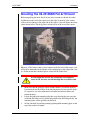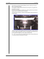
1
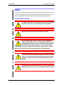
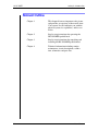
HS-2010MED
AutoCam™ Pan & Tilt Head
Operation, Installation
And Maintenance
(pn AB-300120 for sn 76xxxx0000 - 083100)
i
HS-2010MED Pan & Tilt Head
Safety
IMPORTANT!: Read the Safety Section starting on page 1-2
before installing or using this equipment, or attempting any
adjustment or repair. This safety triangle is used in the manual to
indicate important information. Read this information carefully to
avoid the risk of personal injury, injury to others, or damage to the equipment.
Warning Labels
Various colored safety labels are attached to the AutoCam equipment to alert you to
hazardous situations. The labels and their meaning are described below.
DANGER (with a red background) indicates an imminently
hazardous situation which, if not avoided, will result in death or serious injury.
WARNING (with an orange background) indicates a potentially hazardous situation which, if not avoided, could result in death or serious
injury.
CAUTION (with a yellow background) indicates a potentially
hazardous situation which, if not avoided, may result in minor or moderate
injury.
CAUTION (with a yellow background, but without the Safety
Alert symbol) indicates a potentially hazardous situation which, if not avoided,
may result in property damage.
ii
Critical Data For HS-2010MED
Mass (Weight)
105 lb (48 kg)
Maximum Load
200 lb (90 kg)
Maximum Pressure
Not Applicable
Input Voltage
30 Volts DC (nominal)
Input Current
3 Amps (nominal)
5 Amps (peak)
Date Of Manufacture
2000
iii
Technical Support
If you are based in North, South or Central America and need technical support on
the AutoCam system, contact Vinten Inc. at:
709 Executive Blvd.
Valley Cottage, NY 10989
USA
Phone:1-888 4 VINTEN (1-888-484-6836) - Toll free in the U.S.A.
+1 845-268-0100
Fax:+1 845-268-0113
Or, if you are based outside of North, South or Central America, contact Vinten
Broadcast Limited at:
Western Way
Bury St. Edmunds
Suffolk IP33 3TB
ENGLAND
Phone: +44 (0) 284 752121
Fax: +44 (0) 284 750560
iv
Warranty
Vinten, Incorporated (Vinten) warrants that its equipment shall be free of defects in
material and workmanship for a period of twelve (12) months from the first date of
installation, but no more than eighteen (18) months from date of shipment, and is
extended only to the original purchaser. Vinten, at its option, will repair or replace
defective components. Warranty covers only those defects that occur when the equipment is used in the manner described in the Operation, Installation, and Service manual. Vinten’s liability is limited to parts, material, and labor necessary to repair or
replace equipment manufactured by Vinten. Any and all consequential damages are
excluded. Consumable supplies and normal wear items are the customer’s responsibility and are not covered by this warranty.
The warranty is in effect only when equipment is operated, adjusted, and maintained
in the manner described in the appropriate Operation, Installation, and Service manual. Modifications, service by non-authorized service personnel, failure to provide
proper maintenance, and abuse and misuse of the equipment will void the warranty.
Repairs not covered by this warranty will be billed for parts, labor, and expenses at
the rates in effect at the time of service.
Warranty service and repair will normally be performed at the Vinten factory in Valley Cottage, New York, but may, at the discretion of Vinten, be performed on the customer site. It is the customer’s responsibility to contact Vinten and obtain
authorization prior to returning equipment for warranty service. Returned equipment
must include a Return Material Authorization (RMA) number, and a failure report
describing the nature of the failure or complaint as well as the customer’s name,
address, and a contact name and phone number.
v
Copyright
The Vinten Inc. AutoCam User Manual is copyrighted with all rights reserved. Under
the copyright law, this manual may not be copied, in whole or in part, without written
consent from Vinten Inc.
© 2000 by Vinten Inc.
Disclosure Statement - AutoCam System
This document contains information proprietary to Vinten Inc. Except by written
authorization from Vinten Inc., the information contained in this document shall not,
in whole or in part, be disclosed to third parties, reproduced for any purpose, or used
except for evaluation, operation and maintenance of equipment supplied by Vinten
Inc. or Vinten Broadcast.
Manual Outline
This manual covers the installation, operation and maintenance of the AutoCam HS2010MED Pan/Tilt Head. See Chapter 1 for a detailed description of the contents of
this manual.
Product Serial Numbers
Vinten AutoCam products are marked with unique serial numbers that include a 2
digit product identifier, a 4 digit serial number and a 2 character revision code. The
format is AABBBBXXCD where:
AA
Product Identifier - 76 for the HS-2010MED
BBBB
Serial number
XX
Reserved for future use - currently 00
C
Primary revision status - 0, 1, 2, 3 etc.
D
Secondary revision status - 0, A, B, C etc.
This manual is applicable to products that have serial numbers 76xxxx0000 where
xxxx may be any 4 digit number.
AutoCamTM, Vinten Inc.TM and Lubricated Friction (LFTM) are trademarks of
Vinten Inc. or Vinten Broadcast Limited.
Specifications and features are subject to change without prior notice.
(083100)
vi
Table Of Contents
HS-2010MED Pan & Tilt Head . . . . . . . . . . . . . . . . . . . . . . . . . . . . . ii
Safety . . . . . . . . . . . . . . . . . . . . . . . . . . . . . . . . . . . . . . . . . . . . . . . . ii
Warning Labels . . . . . . . . . . . . . . . . . . . . . . . . . . . . . . . . . . . . . . . . . . . . .ii
Critical Data For HS-2010MED . . . . . . . . . . . . . . . . . . . . . . . . . . . . . . . . iii
Technical Support . . . . . . . . . . . . . . . . . . . . . . . . . . . . . . . . . . . . . iv
Warranty . . . . . . . . . . . . . . . . . . . . . . . . . . . . . . . . . . . . . . . . . . . . . v
Copyright . . . . . . . . . . . . . . . . . . . . . . . . . . . . . . . . . . . . . . . . . . . . . . . . . vi
Disclosure Statement - AutoCam System . . . . . . . . . . . . . . . . . . . . . . vi
Manual Outline . . . . . . . . . . . . . . . . . . . . . . . . . . . . . . . . . . . . . . . . . . . . vi
Product Serial Numbers . . . . . . . . . . . . . . . . . . . . . . . . . . . . . . . . . . . . . vi
1 Safety & Introduction
Safety . . . . . . . . . . . . . . . . . . . . . . . . . . . . . . . . . . . . . . . . . . . . . . 1–2
Very Important Warnings . . . . . . . . . . . . . . . . . . . . . . . . . . . . . . . . . .
Other Important Warnings . . . . . . . . . . . . . . . . . . . . . . . . . . . . . . . . .
Customer Responsibility . . . . . . . . . . . . . . . . . . . . . . . . . . . . . . . . . . .
Safe Working Environment . . . . . . . . . . . . . . . . . . . . . . . . . . . . . . . . .
Operating Footprint And Safe Operating Zone . . . . . . . . . . . . . . .
Warning Signs . . . . . . . . . . . . . . . . . . . . . . . . . . . . . . . . . . . . . . . . . . .
Heads Can Start Unexpectedly . . . . . . . . . . . . . . . . . . . . . . . . . . . .
Power Switch . . . . . . . . . . . . . . . . . . . . . . . . . . . . . . . . . . . . . . . . . . . .
Pinch Points . . . . . . . . . . . . . . . . . . . . . . . . . . . . . . . . . . . . . . . . . . . . .
Sharp Edges . . . . . . . . . . . . . . . . . . . . . . . . . . . . . . . . . . . . . . . . . . . . .
1–2
1–3
1–3
1–3
1–4
1–4
1–4
1–5
1–5
1–5
Manual Outline . . . . . . . . . . . . . . . . . . . . . . . . . . . . . . . . . . . . . . 1–6
HS-2010MED Pan/Tilt Head . . . . . . . . . . . . . . . . . . . . . . . . . . . . . 1–8
Key Features . . . . . . . . . . . . . . . . . . . . . . . . . . . . . . . . . . . . . . . . . . . . 1–8
HS-2010MED Specifications . . . . . . . . . . . . . . . . . . . . . . . . . . . . . . . . 1–9
Typical Applications . . . . . . . . . . . . . . . . . . . . . . . . . . . . . . . . . 1–10
ACP-8000P System . . . . . . . . . . . . . . . . . . . . . . . . . . . . . . . . . . . . . . 1–10
HCP-8000 System . . . . . . . . . . . . . . . . . . . . . . . . . . . . . . . . . . . . . . . 1–11
Multicontroller II System . . . . . . . . . . . . . . . . . . . . . . . . . . . . . . . . . . 1–11
AutoCam Philosophy . . . . . . . . . . . . . . . . . . . . . . . . . . . . . . . . 1–12
Seamless Integration Into The Studio
“Like Being Behind A Camera”
An Easy Transition
1–12
1–12
1–13
2 Operation
Introduction . . . . . . . . . . . . . . . . . . . . . . . . . . . . . . . . . . . . . . . . . 2–2
Location Of Controls . . . . . . . . . . . . . . . . . . . . . . . . . . . . . . . . . . . . . 2–2
Power Switch . . . . . . . . . . . . . . . . . . . . . . . . . . . . . . . . . . . . . . . . . . . . 2–5
vii
Table Of Contents
Turning The Head On
2–5
Locking The Tilt Cradle . . . . . . . . . . . . . . . . . . . . . . . . . . . . . . . . . . . . 2–6
Robotic Mode Of Operation . . . . . . . . . . . . . . . . . . . . . . . . . . . . . . . 2–8
Manual Mode Of Operation . . . . . . . . . . . . . . . . . . . . . . . . . . . . . . . 2–8
Converting From Robotic To Manual Mode . . . . . . . . . . . . . . . . . . 2–8
Setting Pan And Tilt Drag . . . . . . . . . . . . . . . . . . . . . . . . . . . . . . . . . . 2–8
Pan And Tilt Brakes . . . . . . . . . . . . . . . . . . . . . . . . . . . . . . . . . . . . . . 2–10
Converting From Manual To Robotic Mode . . . . . . . . . . . . . . . . . 2–12
3 Installation
Introduction . . . . . . . . . . . . . . . . . . . . . . . . . . . . . . . . . . . . . . . . . 3–2
Tools You Will Need . . . . . . . . . . . . . . . . . . . . . . . . . . . . . . . . . . . . . . 3–2
Mounting The HS-2010MED Pan & Tilt Head . . . . . . . . . . . . . . . 3–4
Mounting The Camera And Payload . . . . . . . . . . . . . . . . . . . . 3–6
HS-2010MED . . . . . . . . . . . . . . . . . . . . . . . . . . . . . . . . . . . . . . . . . . . . . 3–6
Balancing The Payload . . . . . . . . . . . . . . . . . . . . . . . . . . . . . . . 3–9
Horizontal Balance . . . . . . . . . . . . . . . . . . . . . . . . . . . . . . . . . . . . . . 3–9
Vertical Balance . . . . . . . . . . . . . . . . . . . . . . . . . . . . . . . . . . . . . . . . 3–9
Electrical Installation . . . . . . . . . . . . . . . . . . . . . . . . . . . . . . . . . 3–10
HS-2010MED . . . . . . . . . . . . . . . . . . . . . . . . . . . . . . . . . . . . . . . . . . . . 3–12
4 Maintenance And Repair
Safety . . . . . . . . . . . . . . . . . . . . . . . . . . . . . . . . . . . . . . . . . . . . . . 4–2
Heads Can Start Unexpectedly . . . . . . . . . . . . . . . . . . . . . . . . . . . . 4–3
Routine Maintenance . . . . . . . . . . . . . . . . . . . . . . . . . . . . . . . . . 4–4
Checking Balance . . . . . . . . . . . . . . . . . . . . . . . . . . . . . . . . . . . . . . . 4–4
Overall Operation . . . . . . . . . . . . . . . . . . . . . . . . . . . . . . . . . . . . . . . . 4–4
Native Lens Board Calibration . . . . . . . . . . . . . . . . . . . . . . . . . . 4–6
Original Board (marked Native Lens Control) . . . . . . . . . . . . . . . . .
Zoom Calibration
Focus Calibration
Newer Board (marked 020087) . . . . . . . . . . . . . . . . . . . . . . . . . . . . .
Zoom Calibration
Focus Calibration
4–6
4–6
4–7
4–7
4–7
4–8
ENG Lens Calibration . . . . . . . . . . . . . . . . . . . . . . . . . . . . . . . . 4–10
Getting Started
Zoom Calibration
Focus Calibration
Finishing Up
4–10
4–11
4–11
4–11
Electronics Repair . . . . . . . . . . . . . . . . . . . . . . . . . . . . . . . . . . . 4–12
viii
Table Of Contents
Service Philosophy . . . . . . . . . . . . . . . . . . . . . . . . . . . . . . . . . . . . . . 4–12
Safety . . . . . . . . . . . . . . . . . . . . . . . . . . . . . . . . . . . . . . . . . . . . . . . . . 4–12
Theory Of Operation . . . . . . . . . . . . . . . . . . . . . . . . . . . . . . . . . 4–14
System . . . . . . . . . . . . . . . . . . . . . . . . . . . . . . . . . . . . . . . . . . . . . . . .
Power . . . . . . . . . . . . . . . . . . . . . . . . . . . . . . . . . . . . . . . . . . . . . . . . .
Data Bus . . . . . . . . . . . . . . . . . . . . . . . . . . . . . . . . . . . . . . . . . . . . . . .
4 Channel Servo Board . . . . . . . . . . . . . . . . . . . . . . . . . . . . . . . . . .
Analog
Digital
Zoom/Focus Driver . . . . . . . . . . . . . . . . . . . . . . . . . . . . . . . . . . . . . .
Native Lens Control Board . . . . . . . . . . . . . . . . . . . . . . . . . . . . . . . .
Brushless Motors . . . . . . . . . . . . . . . . . . . . . . . . . . . . . . . . . . . . . . . . .
Motor Drive Amplifiers . . . . . . . . . . . . . . . . . . . . . . . . . . . . . . . . . . .
ix
4–14
4–14
4–14
4–14
4–15
4–15
4–15
4–16
4–17
4–17
Table Of Contents
This page left blank intentionally.
x
1
User Manual
Safety & Introduction
1-1
HS-2010MED
Safety & Introduction
Safety
Safety issues including important warnings, risks and related topics are covered
in this section of the manual. It is very important that this information be available to all personnel who will work on or near the AutoCam equipment.
Very Important Warnings
ALWAYS set the tilt axis horizontal and insert the tilt locking
pin before removing any part of the payload equipment.
Know the location of the power switch on the head.
Before removing the camera or other payload equipment
from the head, ALWAYS set the column of the pedestal to its
minimum height (refer to the user manual for your pedestal).
ALWAYS engage the locking pins or latches to prevent the
column from rising (refer to the user manual for your pedestal). Turn the
power OFF at the head AND at the pedestal if it is a robotic model.
NEVER work directly under the camera if the pedestal column is raised. In the unlikely event that the gas pressure supporting the column is lost, the head and payload may drop
quickly.
NEVER attach cables to the head or the camera which could
pull the pedestal over if it is moved with the column extended.
1-2
User Manual
HS-2010MED
Safety & Introduction
Depending on your choice of equipment, the payload in your
application may be up to 200 lb (90 kg) with the HS2010MED. Therefore, to avoid personal injury, or injury to
others, we recommend that each element of the payload (teleprompter, lens, camera etc.) be removed separately. ALWAYS follow the
handling instructions supplied by the manufacturers of the payload equipment. Make sure that you have enough people involved to safely handle the
weight of your payload equipment. (Note: Any time you change the weight
or position of the payload, the head must be rebalanced as described in
Chapter 3.)
Other Important Warnings
1. To avoid personal injury, always exercise caution when working in the
vicinity of energized heads as they can start to move at any time without
warning.
2. Unless it is impossible, you should always de-energize the head (and pedestal if appropriate) before working on any part of the head, the camera/
lens, or any associated equipment.
Customer Responsibility
It is the customer’s responsibility to ensure that the workplace is safe. In normal
operation, the remote controlled heads and payloads in an AutoCam system can
move suddenly and without warning. Since audible warnings are out of the
question in normal television applications, it is recommended that only trained
personnel be allowed to work in the active areas where the remote controlled
heads and payloads are located. As part of the training, personnel must be made
aware of the hazards of working in a robot environment, including the specific
hazards listed below. The forces are sufficient to cause personal injury, or injury
to others and therefore, caution is essential.
Safe Working Environment
Each of the remote control heads should be within the view of the operator of
the AutoCam system at the control panel. Before and during remote operation,
the operator must verify visually that the active area is clear. If personnel are too
close to one of the heads that is about to move, the operator can prevent the
motion from starting, or stop the motion after it has started.
If the direct line of sight is obstructed in your installation, it is recommended
that one or more viewing cameras are installed to cover the active areas and
allow the operator to view the entire work-space at all times.
User Manual
1-3
HS-2010MED
Safety & Introduction
Operating Footprint And Safe Operating Zone
In most installations, the teleprompter is the piece of equipment mounted on the
head that protrudes the furthest. Or, it may be the manual control bars on the rear
that protrude the furthest. The operating footprint must take into account the
overhang of the teleprompter and/or manual control bars as the head pans, tilts
and is raised or lowered.
If your operating practices require personnel to work less than 3 feet (1m) outside the operating footprint, you must make sure that they are trained and are
aware of the hazards of working in a robot environment, including the specific
hazards listed below. The forces are sufficient to cause personal injury, or injury
to others and therefore, caution is essential.
Warning Signs
Warning signs should be displayed prominently in the workplace as a reminder
to trained personnel, and a primary warning to untrained personnel and visitors.
A typical sign might read:
WARNING:
Robotic Pedestals, Heads & Cameras
Move Suddenly Without Warning
Heads Can Start Unexpectedly
The hazards associated with robotic camera systems are only slightly different
than those associated with operating a camera under conventional manual control. The speeds and camera weights are similar. The main difference is that with
automation, the operator is normally not near the cameras, and it is more difficult to verify that the area is clear. For personnel working on or near the pedestals, they must be aware that the equipment can start moving unexpectedly.
All personnel should be trained and aware of the hazards of robotic heads, and
the fact that they can move at any time. They must be trained on how far the
heads and payloads can move, the speeds involved, and the need to stay back an
appropriate distance.
Most adjustments to the camera and head, such as tilt balancing and camera
video, should be made with the system de-energized. However, if adjustments
are absolutely necessary while the head is powered, they should only be made
by trained technical personnel familiar with the AutoCam robotics system. They
must understand that the camera can move unexpectedly at any time, and must
position themselves so that any motion will not cause them personal harm.
When the robotic heads move, the speeds involved are fairly slow. However, the
equipment is still capable of generating sufficient force to cause injury. Therefore, it is essential that you exercise caution. In particular, be aware that the teleprompter is usually the fastest swinging element.
1-4
User Manual
HS-2010MED
Safety & Introduction
Any failure of the system could possibly cause one or more axes to move on
their own, but the speeds and forces should not be noticeably greater than those
encountered during normal use.
Power Switch
If you need to disable a head in an emergency, or for any other reason, use the
Power Switch on the side of the head
After clearing the cause for the emergency, or completing the maintenance task,
turn the Power Switch back on.
Pinch Points
Particular care should be exercised around possible points where you could get
pinched, such as the tilt cradle. Here, the forces can be somewhat greater, due to
the short lever arm.
Sharp Edges
If the lens, teleprompter or other camera attachments have sharp edges that
could cause injury, make sure they are padded or protected.
User Manual
1-5
HS-2010MED
Safety & Introduction
Manual Outline
1-6
Chapter 1
This chapter discusses important safety issues
and provides an overview of the overall AutoCam system. It will familiarize you with the
physical system, its capabilities, and its ease
of use.
Chapter 2
Step by step instructions for operating the
HS-2010MED pan/tilt head.
Chapter 3
Step by step instructions for unpacking and
installing the HS-2010MED pan/tilt head.
Chapter 4
Technical information including routine
maintenance, circuit descriptions, calibration, schematics and parts lists.
User Manual
HS-2010MED
Safety & Introduction
This page left blank intentionally.
User Manual
1-7
HS-2010MED
Safety & Introduction
HS-2010MED Pan/Tilt Head
Key Features
• 200 lb. (90 kg) payload
• 90 arc second accuracy
• Manual/Remote head with easy change-over
• Electronic drag system
• Brushless servo technology
• Robust construction
The HS-2010MED is a servo pan & tilt head designed to support any combination of camera, lens, viewfinder and teleprompter up to a maximum payload of
200 lbs. (90 kg) This makes it the ideal choice for broadcast studios and video
production facilities. The HS-2010MED is designed as a dual purpose head that
can be operated in servo control mode for remote operation or in full manual
mode.
In manual mode, the electronic drag system delivers the smooth and continuously variable drag over a wide range.
The HS-2010MED is a post head which provides perfect balance about the horizontal and vertical centers of gravity. Excellent performance is achieved in both
remote and manual modes.
Features of the HS-2010MED include: 20 bit servo precision for 90 arc second
accuracy (0.25” at 50 feet); non-lubricated, self-aligning gear train and rugged
1-8
User Manual
HS-2010MED
Safety & Introduction
construction. The high gain digital/analog servo amplifiers provide swift motor
response. This combined with an extremely rigid mechanical design allows tight
damping without oscillation or overshoot.
Control of zoom and focus is possible with full servo studio and ENG lenses. In
the case of an ENG lens, the HP-ZFSLD Lens Drive may be attached to provide
motors and follow pots for servo operation. The full zoom and focus ranges are
covered at a proportional speed in a minimum of one second, dependent on lens
type.
HS-2010MED Specifications
User Manual
Weight
48 kg (105 lb)
Payload
90 kg (200 lb)
Pan Range
359°
Tilt Range (typical)
±20° (may be reduced by actual payload and CG balance adjustments)
Note: The electrical range of the tilt
servo is ±180°
Accuracy
90 arc secs
Angular Acceleration
180°/sec2
Angular Velocity (max)
60°/sec
Angular Velocity (min)
0.1°/sec
Height
24” (61 cm)
Width
20” (51 cm)
Depth
10” (25 cm)
Mounting
Pedestal
Servo Type
Digital with brushless DC motor
Gear-train Type
Self lubricating, anti-backlash
1-9
HS-2010MED
Safety & Introduction
Typical Applications
The HS-2010MED pan & tilt head can be mounted on the AutoCam™ SP-2000/
X-Y free roaming servo pedestal, SP-2100Z Elevating Pedestal or manual pedestals such as Vinten’s Fulmar or Quattro models. NOTE: Make sure that the
total load (head and payload) does not exceed the capacity of your pedestal. For
example, a fully loaded HS-2010MED will exceed the capacity of a Quattro
pedestal.
Up to eight pedestals and heads can be controlled remotely with the AutoCam™
ACP-8000P touchscreen controller. For applications without servo pedestals, the
HCP-8000 touchscreen controller or the compact MultiController II can be
used. Communication between the head and the controller is by RS-422 data.
Refer to the User Manuals for your specific pedestals and controllers for more
information.
ACP-8000P System
In systems with one or more (up to eight) servo pedestals, the ACP-8000P controller is used as shown below
The distance between the controller and rack mounted power supply can be up
to a maximum of 5000 ft. (1500 m). With manual pedestals, the power/data
cable connects the power supply directly to the head up to a maximum distance
of 500 ft. (150 m). With servo pedestals, the power/data connection is made
from the power supply to the pedestal (maximum distance 180 ft or 55 m) and
then looped up to the head.
1-10
User Manual
HS-2010MED
Safety & Introduction
HCP-8000 System
In systems that have no servo pedestals (that is, manual pedestals or fixed
mounting), the HCP-8000 controller is used as shown below.
The distance between the controller and rack mounted power supply can be up
to a maximum of 5000 ft. (1500 m). The power/data cable connects the power
supply to the head up to a maximum distance of 500 ft. (150 m).
Multicontroller II System
The Multicontroller II is a mid scale controller that controls up to six AutoCam
heads of mixed types, including the HS-2010MED. The Multicontroller II is
ideally suited for small and medium size legislative and broadcast applications
such as city halls, compact studios and remote trucks.
User Manual
1-11
HS-2010MED
Safety & Introduction
AutoCam Philosophy
The underlying goal of AutoCam is to build on the proven operating practices of
today’s studios. Immense amounts of time and effort have gone into optimizing
these procedures, and it would be a mistake to suggest any significant change for
the sake of automation. Instead, camera automation should blend into and
enhance the present studio environment, offering its substantial operating economies. On news and similar sets, one operator typically can control all of the
cameras and often the CCU functions as well; and has no difficulty staying well
ahead of the shots.
From the outset, AutoCam was a top-down design, culminating years of discussions with network, affiliate, independent, and EFP visionaries. It was engineered to be expandable to accommodate the largest installations, such as 8camera robotic-dolly studios on multiple floors, controlled from multiple locations. Yet it is also scaleable to the simplest single camera EFP assignments. The
identical system architecture is employed across this entire range of installations. Software configuration screens on the console are used to configure each
installation; as opposed to customized hardware. This stable architecture philosophy has many benefits: easy system expansion or upgrading, better factory support, and higher reliability.
Seamless Integration Into The Studio
Successful camera automation should be as transparent as possible to the studio
staff, and particularly to the director. He or she should expect the same communications with the camera console operator, as with multiple camera operators in
a traditional studio. As before, a named shot from the run-down list is relayed
over the headsets. But the operator now no longer needs to continually re-frame
those shots. They only need to be taught once at the console, and given the same
names that the director uses. Then, when each camera and shot is called over,
the operator touches that name on the touch screen, sending the specified camera to that shot. AutoCam is also flexible and intuitive, and changes in the rundown are easily accommodated. Stories may readily be dropped or stretched or
reordered as studio events unfold in a dynamic manner.
“Like Being Behind A Camera”
Effective camera automation should also be as transparent as possible to the
camera operator. In designing the console, a great deal of effort was devoted to
presenting essentially the same controls that are present at the camera: a pan/tilt
“bar”, and zoom, focus, pedestal, and dolly controls. Further, considerable engineering went into making the controls smooth and responsive, so that they have
a quality feel like the controls on a camera. This allows both fast and reflexive
operation, and superior on-air movement quality. To complete the “behind-thecamera” analogy, a color monitor at the console reproduces the viewfinder. The
1-12
User Manual
HS-2010MED
Safety & Introduction
big difference is that at the touch of a finger, not one but up to eight cameras can
now be controlled.
The heart of the friendliness of the console is the color touch screen. It presents
all of the information the operator needs in one place, in a plain-language manner. The video underlay and the control sticks are assigned together and dynamically to the last camera event selected. Colors are used in a powerful and
consistent manner to convey important information; such as which named shot
each camera is framing, which keys are logical to be touched next, and which
camera is on-air. Information on the screen is intelligently limited and dynamically updated; only the touch-keys that have meaning in a given situation are
shown.
Going one step beyond remote camera control, the console adds the capability to
memorize essentially any camera event, from a simple shot to a dolly bumper or
group move. The operator now “manages by exception”, directing AutoCam to
frame the shots, and then trimming them as necessary.
An Easy Transition
Everyone is concerned that the transition to automation be quick and painless.
AutoCam facilitates this by adopting the genre and jargon of the studio, and
delivering stable software yet reconfigurable hardware. A measure of the success of this philosophy is how easy it is to install AutoCam and train operators to
use the system. Stations have installed 3-camera dolly systems in one day, and
aired programs the next.
User Manual
1-13
HS-2010MED
Safety & Introduction
This page left blank intentionally.
1-14
User Manual
2
User Manual
Operation
2-1
HS-2010MED
Operation
Introduction
This chapter covers operation of the pan and tilt head and is limited to the
switches, controls and other features on the heads themselves.
Operating procedures for controlling the head remotely are described in the
User Manual for the specific controller in your installation.
Location Of Controls
Refer to the following illustrations to locate the various controls. Use of the controls is described in the next section.
Tilt Drag
Adjustment
Manual/Robotic
Switch
Pan Brake Lever
2-2
User Manual
HS-2010MED
Operation
Tilt Brake Lever
Pan Drag Knob
User Manual
2-3
HS-2010MED
Operation
Power Switch
2-4
User Manual
HS-2010MED
Operation
Power Switch
The power switch on the head enables or disables all of the electronics in the
head. Turn the power off when you are working on the head or associated equipment. The power switch can also be used to disable the head in an emergency.
Power Switch
(Up = | = On)
(Down = O = Off)
Turning The Head On
WARNING: ALWAYS turn on the HS-2010MED power with
the head set for Robotic mode of operation.
Make sure that the controller and servo pedestal (if installed) are turned on and
initialized before you turn the head on.
User Manual
2-5
HS-2010MED
Operation
Locking The Tilt Cradle
The tilt locking pin is provided to mechanically lock the tilt cradle in the horizontal position. The tilt locking pin is clipped to the side of the tilt cradle when
not in use as shown below.
WARNING: Any time that you are working on the camera,
lens, teleprompter, particularly if you are adding or removing
equipment, use the tilt locking pin to lock the tilt cradle in the
horizontal position. This will prevent an unbalanced load
from shifting unexpectedly.
Tilt Locking Pin
(Stored)
WARNING: ALWAYS turn the head power switch OFF
before installing the tilt locking pin. Operating the head with
the pin installed will cause serious damage.
With the tilt cradle approximately horizontal, insert the locking pin through the
access hole in the cover (see opposite) and push it all the way through into the
tilt cradle. You may need to rock the tilt cradle back and forth slightly to fully
seat the locking pin. Always return the locking pin to the tilt cradle clips after
use.
2-6
User Manual
HS-2010MED
Operation
Tilt Locking Pin
(Cradle Locked)
User Manual
2-7
HS-2010MED
Operation
Robotic Mode Of Operation
The head is normally shipped from the factory in Robotic mode. In this mode,
you will only need to use the power switch on the head. The other operational
controls on the head are not used. However, you should always check to make
sure that the pan and tilt brakes are not engaged in Robotic mode - refer to
the Pan And Tilt Brakes section later in this chapter.
Refer to the User Manual for your controller to operate the head.
Manual Mode Of Operation
Local control of the pedestal/pan/tilt/zoom/focus is sometimes desirable for
moving a camera between studios, general maintenance, or for shows which do
not lend themselves to robotics operation. The head is operated with the pan
bars (and the associated lens controls) just like a conventional (non-robotic) pan
and tilt head. Electronic drag adjustment is provided for pan and tilt and the pan
and tilt brakes can be used for a locked off shot. Converting from Robotic to
Manual mode (and back) is described in the next section.
WARNING: Do not operate the head manually by just turning the power off. You can cause operational problems and/or
electrical damage.
If you turn the head off (with the power switch), it may feel comfortable for
manual operation even though the drag is not engaged. However, DO NOT operate in this manner. The pan and tilt servo motors act as voltage generators and
can cause interference with the lens servos. In addition, the voltage generated
can cause electrical failures in the HS-2010MED electronics.
Converting From Robotic To Manual Mode
If you are in Robotic control and want to change over to Manual control, use the
changeover switch on the top of the tilt housing to change modes.
Setting Pan And Tilt Drag
In manual mode, the pan and tilt drag can be adjusted as desired by the camera
operator. The drag settings are for manual mode only and have no effect in
Robotic mode.
2-8
User Manual
HS-2010MED
Operation
Adjust the pan drag knob on the pan housing for the desired amount of drag as
you pan the camera left and right. Turn the knob clockwise for more drag or
counterclockwise for less drag.
Pan Drag Knob
Adjust the tilt drag knob on the top of the tilt housing for the desired amount of
drag as you tilt the camera up and down. Turn the knob clockwise for more drag
or counterclockwise for less drag.
Tilt Drag Knob
User Manual
2-9
HS-2010MED
Operation
Pan And Tilt Brakes
WARNING: NEVER use the pan or tilt brake in Robotic
mode. You will cause serious damage.
If the head is correctly balanced (see Chapter 3), you should not need to use the
pan and tilt brakes at all. Due to the risk of damage if the brakes are left engaged
by mistake, the best practice is to always leave the brakes disengaged.
The pan brake lever is located under the housing and is shown in the disengaged
position. Flip the lever to the opposite side to engage the brake.
Pan Brake Lever
Off ---- On
2-10
User Manual
HS-2010MED
Operation
The tilt brake lever is located on the housing under the tilt cradle and is shown in
the disengaged position. Flip the lever to the opposite side to engage the brake.
Tilt Brake Lever
On ---- Off
User Manual
2-11
HS-2010MED
Operation
Converting From Manual To Robotic Mode
WARNING: When switching from Manual mode to Robotic
mode, be prepared for the head to move suddenly as the servos seek the position setting from the controller.
1.
2.
2-12
Make sure that the pan and tilt brakes are Off.
Use the changeover switch on the top of the tilt housing to change
modes.The servos will seek the last position setting from the controller.
User Manual
3
User Manual
Installation
3-1
HS-2010MED
Installation
Introduction
This chapter focuses on the mechanical aspects of unpacking the head(s),
mounting the heads on the pedestals (or tripods or other mounts), mounting and
balancing the camera and payload.
TO PREVENT PERSONAL INJURY, AND FOR PROPER
PERFORMANCE OF THE EQUIPMENT IT IS ESSENTIAL THAT THE PROCEDURES IN THIS MANUAL ARE
FOLLOWED EXACTLY.
DO NOT ATTEMPT TO LIFT OR MOUNT THE HS2010MED HEAD UNLESS YOU HAVE AT LEAST ONE
OTHER PERSON TO HELP YOU.
Tools You Will Need
You will need the following tools during the unpacking and installation:
•
•
3-2
9/16” open end wrench
A set of hex keys
User Manual
HS-2010MED
Installation
This page left blank intentionally.
User Manual
3-3
HS-2010MED
Installation
Mounting The HS-2010MED Pan & Tilt Head
Before unpacking the head, decide if you want to mount it with the tilt cradle
and housing to the left of the camera or to the right. In general, if the camera
cable or triax connects to the right side of the camera, you will choose the orientation shown below. The head power switch will be to the rear of the camera.
However, if the camera cable or triax connects to the left side of the camera, you
will want to mount the head with the cradle and housing to the right of the camera. In this orientation, the head power switch will be to the front.
Do not mount the head in one orientation and attempt to
rotate it 180° because you will misalign the servo drive train.
1.
2.
3.
3-4
Make sure that the pedestal, tripod or other mount is in position ready to
have the head installed. Refer to the documentation for your specific pedestal, tripod etc. for safety information and other instructions before you
mount the head.
Locate the four head mounting bolts that are packed in the accessory box
inside the SP-2000 crate. If you did not purchase the SP-2000 pedestal, the
mounting bolts will be packed with the head.
Set the four bolts in position pointing up through the mounting plate on the
top of the pedestal or tripod.
User Manual
HS-2010MED
Installation
4.
5.
6.
7.
Open the box containing the head. Remove and set aside any accessory
items and packing material.
Two people can then lift the head from its box and place it in position on
the pedestal or tripod.
Install the tilt locking pin to hold the tilt cradle in position (leave the locking pin in place until the payload is mounted).
Align the holes in the base of the head with the bolts in the top of the pedestal or tripod.
Insert And Tighten 4 Bolts (1 Bolt Hidden In Photo)
8.
9.
User Manual
With at least one person supporting the head in position, start the four bolts
by hand, making sure that they are not cross threaded. It may be necessary
to move the head slightly to exactly align it with the bolts.
Use a 9/16” open end wrench to tighten the four bolts evenly until the head
is securely fastened to the pedestal or tripod.
3-5
HS-2010MED
Installation
Mounting The Camera And Payload
DO NOT ATTEMPT TO LIFT OR MOUNT THE PAYLOAD
EQUIPMENT UNLESS YOU HAVE AT LEAST ONE
OTHER PERSON TO HELP YOU.
To keep the weight and size manageable, it is recommended that you install the
camera onto the head first. Then add the lens, teleprompter and other payload
equipment. Estimate the position of the overall center of gravity to simplify the
balancing steps later on.
HS-2010MED
The HS-2010MED uses a Slide Plate Assembly between the camera and the tilt
cradle. Usually, you can transfer the camera and teleprompter mounting plate as
a single unit and bolt it to the Slide Plate Assembly. The zoom and focus handles
for manual operation attach to brackets on the Slide Plate Assembly.
1. If it is not already installed, un-clip the locking pin from the tilt cradle and
insert it through the hole in the back of the housing and fully seat it to lock
the cradle in the horizontal position.
2. Use a 1/4” hex key to make sure that the four tilt cradle screws are tight.
Tilt Cradle Screws
Slide Lock
3-6
User Manual
HS-2010MED
Installation
3.
Attach the Slide Plate Assembly to the camera or teleprompter plate using
the two mounting screws provided. Choose the mounting holes that will
position the estimated center of gravity in the center of the Slide Plate
Assembly. Tighten the screws securely.
Mounting Screws
Slide Plate Assembly
4.
5.
Loosen the Slide Lock on the tilt cradle and slide the camera and Slide
Plate into the tilt cradle. Slide the payload forwards or backwards until the
estimated center of gravity of the payload is in the center of the tilt cradle.
Tighten the Slide Lock securely.
Install the safety stop block in the bottom of the Slide Plate.
Safety Stop Block
6.
Mount the lens, teleprompter and other payload equipment such as the
manual lens controls.
7. Support the payload in case it is unbalanced, remove the tilt locking pin
and store it in the clips on the tilt cradle.
Balance the payload - see the next section of this chapter.
User Manual
3-7
HS-2010MED
Installation
This page left blank intentionally
3-8
User Manual
HS-2010MED
Installation
Balancing The Payload
DO NOT ATTEMPT TO BALANCE THE PAYLOAD
UNLESS YOU HAVE AT LEAST TWO OTHER PEOPLE
TO HELP YOU.
For proper operation of the HS-2010MED pan/tilt heads it is very important that
the payload is mechanically balanced horizontally (forwards and backwards)
and vertically. This ensures that the center of gravity is exactly on the tilt axis
and the load on the servos is balanced.
Horizontal Balance
Make sure that the head power switch is Off.
1. If the payload stays in the horizontal position without support it is already
balanced.
2. If it is not balanced, have two or more people support the payload, release
the Slide Lock and move the payload forwards or backwards until it is balanced.
3. Tighten the Slide Lock and recheck the balance. It is best to move the payload in small increments even though this may require several steps until
the balance is achieved.
Vertical Balance
Once the horizontal balance is set, you can adjust the vertical balance.
1. Manually tilt the camera approximately 45° upwards and release it. If it
continues to move upwards, the payload is mounted too high. Or, if it
moves back towards the horizontal position when you release it, the payload is mounted too low. If the camera stays in the same position when
released, the payload is properly balanced vertically. Tilt the camera 45° in
the other direction and release it and check balance again.
2. Mark the starting position of the tilt cradle so that you can keep track of
how far you move it as you set vertical balance.
3. This step requires several people, since it is impossible and unsafe for just
one or two people to accomplish it. While two or more people support the
weight of the payload, use a 1/4” right angle hex key to loosen the four tilt
cradle mounting screws.
4. Based on the test in step 1, raise or lower the payload and tilt cradle a small
amount. Tighten the four screws securely.
5. Repeat the test in step 1 and repeat steps 3 and 4 until vertical balance is
achieved.
User Manual
3-9
HS-2010MED
Installation
Electrical Installation
A typical AutoCam system configuration is shown below. Installation of the
controller, pedestals and other equipment is described in the User manuals for
those products.
Video Switcher
Video Switcher
ACP-8000P
ACP-8000P
Note the pedestals may be robotic (as shown) or manual.
Electrical connections for the HS-2010MED head are described in the next section.
3-10
User Manual
HS-2010MED
Installation
This page left blank intentionally.
User Manual
3-11
HS-2010MED
Installation
HS-2010MED
Electrical connections are made via the two connectors on the head. These connectors are on the opposite side from the head power switch.
1.
2.
3.
Locate the cables supplied with your equipment.
Install the lens control cable from the 26 pin D connector on the head to the
lens.
Install a cable from the Power/Data Connector on the head to the appropriate source depending on the equipment in your system as listed below.
System Equipment
Cable Type
Connect To
SP-2000/X-Y
SP-CAB-8
Power/Data Out On Pedestal
SE-1000
HP-SP-CAB-10
Power/Data Out On SE-1000
ACP-8000P
SP-CAB-xx
Power Supply Power/Data Out
LCP-8000
SP-CAB-xx
Power Supply Power/Data Out
HCP-8000
SP-CAB-xx
Power Supply Power/Data Out
MultiController 2
SP-CAB-xx
Power Supply Power/Data Out
In the table above, “xx” denotes the cable length in feet (m x 0.3).
3-12
User Manual
HS-2010MED
Installation
4.
5.
User Manual
Install the rest of the equipment in your system as described in the relevant
User Manual(s).
Power up the elements of your system as described in the relevant User
Manual(s).
3-13
HS-2010MED
Installation
This page left blank intentionally.
3-14
User Manual
4
User Manual
Maintenance And Repair
4-1
HS-2010MED
Maintenance And Repair
Safety
ALWAYS set the tilt axis horizontal and insert the tilt locking
pin before removing any part of the payload equipment.
Know the location of the power switch on the head.
Before removing the camera or other payload equipment
from the head, ALWAYS set the column of the pedestal to its
minimum height (refer to the user manual for your pedestal).
ALWAYS engage the locking pins or latches to prevent the
column from rising (refer to the user manual for your pedestal). Turn the
power OFF at the head AND at the pedestal if it is a robotic model.
NEVER work directly under the camera if the pedestal column is raised. In the unlikely event that the gas pressure supporting the column is lost, the head and payload may drop
quickly.
Depending on your choice of equipment, the payload in your
application may be up to 200 lb. (90 kg). Therefore, to avoid
personal injury, or injury to others, we recommend that each
element of the payload (teleprompter, lens, camera etc.) be
removed separately. ALWAYS follow the handling instructions supplied by
the manufacturers of the payload equipment. Make sure that you have
enough people involved to safely handle the weight of your payload equipment. (Note: Any time you change the weight or position of the payload, the
head must be rebalanced as described in Chapter 3.)
4-2
User Manual
HS-2010MED
Maintenance And Repair
To avoid personal injury, always exercise caution when working in the vicinity of energized heads as they can start to move
without any warning. Unless it is impossible, you should
always de-energize the head (and pedestal if appropriate)
before working on any part of the head, the camera/lens, or any associated
equipment.
Heads Can Start Unexpectedly
The hazards associated with robotic camera systems are only slightly different
than those associated with operating a camera under conventional manual control. The speeds and camera weights are similar. The main difference is that with
automation, the operator is normally not near the cameras, and it is more difficult to verify that the area is clear. For personnel working on or near the pedestals, they must be aware that the equipment can start moving unexpectedly.
All personnel should be trained and aware of the hazards of robotic heads, and
the fact that they can move at any time. They must be trained on how far the
heads and payloads can move, the speeds involved, and the need to stay back an
appropriate distance.
Most adjustments to the camera and head, such as tilt balancing and camera
video, should be made with the system de-energized. However, if adjustments
are absolutely necessary while the head is powered, they should only be made
by trained technical personnel familiar with the AutoCam robotics system. They
must understand that the camera can move unexpectedly at any time, and must
position themselves so that any motion would not cause them personal harm.
When the robotic heads move, the speeds involved are fairly slow. However, the
equipment is still capable of generating sufficient force to cause injury. Therefore, it essential that you exercise caution. In particular, be aware that the teleprompter is usually the fastest swinging element.
Any failure of the system could possibly cause one or more axes to move on
their own, but the speeds and forces should not be noticeably greater than those
encountered during normal use.
User Manual
4-3
HS-2010MED
Maintenance And Repair
Routine Maintenance
In general, AutoCam is a highly reliable and stable product. The electronics are
well ventilated and highly rated. The number of connectors is kept to a minimum and the best quality connectors are used. The HS-2010MED and pan/tilt
head incorporate a pre-loaded gear train which is either non-lubricated or in certain sections, sealed and permanently lubricated and therefore requires no routine maintenance. However, overall balance and smoothness of operation should
be checked periodically.
Checking Balance
In normal operation, the only reason for balance to change is if the camera is
moved for service or if the overall load is changed. However, it is recommended
that you check the balance once a week to ensure reliable operation and reduce
excessive wear and overheating that can be caused by operating with an unbalanced load.
1. Set the tilt cradle horizontal using the controller joystick.
2. Switch off the power at the head.
3. If the head tends to drift away from the horizontal position, the forward/
backward position of the load must be adjusted to reset the horizontal balance (refer to Chapter 3).
4. Tilt the head 45° upward and release it. If the head continues to move
upwards, the payload is mounted too high. On the other hand, if the camera
moves back towards the horizontal position when you release it, the payload is mounted too low. If the camera stays in the same position when
released, the payload is properly balanced vertically.
5. Refer to Chapter 3 if you need to reset horizontal and/or vertical balance.
Overall Operation
Once a week, use the controller joystick to exercise pan, tilt and zoom operation.
Observe the response of the head and lens which should be smooth and consistent throughout the entire range. Similarly, check focus operation using the
Focus knob on the controller.
4-4
User Manual
HS-2010MED
Maintenance And Repair
This page left blank intentionally.
User Manual
4-5
HS-2010MED
Maintenance And Repair
Native Lens Board Calibration
The Native Lens Control Board allows use of the motors and feedback potentiometers already provided in many servo controlled lenses and saves the cost and
complexity of adding outboard hardware. During the system installation, one of
these boards is mounted in each lens. A typical installation is shown below.
Native Lens Board
The board itself may look different than the illustration because two different
types of Native Lens Board are in use. The marking on the board (“Native Lens
Control” denotes the original board, or “020087” denotes the newer board) will
determine which calibration procedure you should use.
With HS-2010MED heads, zoom and focus handles are provided for manual
operation. A relay in the Native Lens Board switches between the AutoCam
zoom and focus control voltages and the control voltages from the pan bar controls.
Original Board (marked Native Lens Control)
The board is normally factory set to allow the zoom and focus controls to operate over a limited range with virtually any lens. Setting these pots is an iterative
process due to the interaction of the adjustments.
Zoom Calibration
1. Observe the zoom element of the lens while using the controller joystick to
run the zoom from fully wide to fully tight.
2. If the lens is reaching the mechanical end stop at either end of travel, adjust
VR1, Zoom Gain to reduce the total travel so that the lens does not reach
the end stop(s).
4-6
User Manual
HS-2010MED
Maintenance And Repair
3.
4.
Adjust VR2, Zoom Centering so that the range of travel is centered within
the overall range from end stop to end stop as the controller joystick is
exercised.
Readjust VR1, Zoom Gain to increase the total travel so that the lens just
reaches both end stops. Trim VR2, Zoom Centering as necessary to ensure
that the travel is symmetrical.
Focus Calibration
1. Observe the focus element of the lens while using the controller Focus
Knob to run the focus from far to near.
2. If the lens is reaching the mechanical end stop at either end of travel, adjust
VR3, Focus Gain to reduce the total travel so that the lens does not reach
the end stop(s).
3. Adjust VR4, Focus Centering so that the range of travel is centered within
the overall range from end stop to end stop as the controller Focus Knob is
exercised.
4. Readjust VR3, Focus Gain to increase the total travel so that the lens just
reaches both end stops. Trim VR4, Focus Centering as necessary to ensure
that the travel is symmetrical.
Newer Board (marked 020087)
1. Make sure that the jumpers marked JP2 and JP3 are removed.
2. Power up the HS-2010MED head and allow it to initialize.
3. At the controller (ACP, HCP or LCP), select CONFIG, then ENGINEERING SCREEN and type in the password MAINT.
4. Select REAL TIME STATUS and adjust the zoom and focus controls on
the control panel to set the demand voltages to 50.00.
5. Connect the negative lead of a digital voltmeter to the cathode (striped end)
of D2.
6. Connect the positive lead of the voltmeter to pin 22 of output connector J2.
Make a note of this lens reference voltage.
Zoom Calibration
7. Measure the voltage at jumper JP2. Adjust R21 (Zoom Center) so that the
voltage at JP2 is equal to the lens reference measured in step #6.
8. Monitor the voltage at JP2 and use the zoom control on the control panel to
run through the entire zoom range. Adjust R4 (Zoom Range) for full travel
of the lens.
9. Reset the zoom control for 50.00 in the Real Time Status screen. If necessary, adjust R21 (Zoom Center) so that the voltage at JP2 is equal to the
lens reference measured in step #6.
10. Repeat step #8.
User Manual
4-7
HS-2010MED
Maintenance And Repair
11. The voltage at JP2 should always be positive. If it goes negative, R4 until it
remains positive throughout the zoom range.
Focus Calibration
12. Measure the voltage at jumper JP3. Adjust R22 (Focus Center) so that the
voltage at JP3 is equal to the lens reference measured in step #6.
13. Monitor the voltage at JP3 and use the focus control on the control panel to
run through the entire zoom range. Adjust R8 (Focus Range) for full travel
of the lens.
14. Reset the focus control for 50.00 in the Real Time Status screen. If necessary, adjust R22 (Focus Center) so that the voltage at JP3 is equal to the
lens reference measured in step #6.
15. Repeat step #13.
16. The voltage at JP3 should always be positive. If it goes negative, R8 until it
remains positive throughout the zoom range.
4-8
User Manual
HS-2010MED
Maintenance And Repair
This page left blank intentionally.
User Manual
4-9
HS-2010MED
Maintenance And Repair
ENG Lens Calibration
For systems that use ENG style lenses, the lens servo in the head must be calibrated to ensure that the controller is capable of generating full end to end
motion of the lens elements for zoom and focus.
Getting Started
Use a hex key to remove the access cover in the housing.
Access Cover
Locate and identify the calibration pots and switches.
Zoom Wide
Zoom Tight
Focus Near
Focus Range
Zoom Range
Focus Far
4-10
User Manual
HS-2010MED
Maintenance And Repair
Zoom Calibration
1. Use the controller joystick to zoom the lens to its widest angle.
2. Observe the zoom element of the lens and adjust R2 (ZW) until it just
reaches the mechanical end stop.
3. Use the controller joystick to zoom the lens to its tightest angle.
4. Observe the zoom element of the lens and adjust R1 (ZT) until it just
reaches the mechanical end stop.
5. Repeat steps 1 through 4 and readjust R2 and R1 if necessary.
6. If R1 and R2 do not have enough range to drive the zoom element of the
lens to its mechanical end stops, set the Zoom Range DIP switch to the
other position and repeat the calibration steps.
Focus Calibration
1. Use the controller Focus Knob to focus the lens at the maximum distance.
2. Observe the focus element of the lens and adjust R4 (FF) until it just
reaches the mechanical end stop.
3. Use the controller Focus Knob to focus the lens at the minimum distance.
4. Observe the focus element of the lens and adjust R3 (FN) until it just
reaches the mechanical end stop.
5. Repeat steps 1 through 4 and readjust R4 and R3 if necessary.
6. If R3 and R4 do not have enough range to drive the focus element of the
lens to its mechanical end stops, set the Focus Range DIP switch to the
other position and repeat the calibration steps.
Finishing Up
Replace the access cover and secure it with the screws removed earlier.
User Manual
4-11
HS-2010MED
Maintenance And Repair
Electronics Repair
Service Philosophy
Servicing is supported at three levels by Vinten Inc. after the warranty period
expires:
• On-site service may be contracted from Vinten Inc. or through the
local representative from which the system was purchased.
• Board-level replacement may be readily accomplished by station
personnel, using stocked or ordered circuit boards.
• Component level replacement is feasible to some extent, by qualified station engineers or technicians, using the material in this
chapter.
Service questions may be directed to factory service specialists at Vinten Inc. in
Valley Cottage, NY, by phone at 1-845-268-0100, or toll free (in the U.S.A.) at
1-888 4 VINTEN (1-888-484-6836). You can also fax Vinten at 1-845-2680113. An emergency telephone service is available 24 hours a day, seven days a
week using the 1-845-268-0100 number (or 1-888-484-6836, toll free in the
U.S.A).
To streamline service and support, the same boards are used in multiple locations wherever possible. This allows you to swap boards in many cases to isolate
a fault. For example, the 503 Power Amplifier (motor driver) is used twice in
each head and (and six times in each SP-2000 pedestal). The 4 Channel Servo
Board in the head is also used twice in each SP-2000 pedestal. Note however,
that the jumper setting (J1) on the 4 Channel Board must be changed depending
on whether it is used for Steer, Drive or Pan/Tilt.
Safety
Service should only be performed by qualified personnel, who
are familiar with the equipment. At some points inside the
power supplies 120 (or 240) volts AC is exposed, with a danger
of electrical shock. Unless there is a power supply failure, the
highest voltage present in the cable or head should be no more than ±42
VDC. The normal unregulated supply voltages supplied to the head are ±30
VDC.
If you must work on a head that is powered up, place a large
WARNING sign at the controller to alert other personnel that
they should not attempt to use the system.
4-12
User Manual
HS-2010MED
Maintenance And Repair
Some maintenance procedures must be performed with the
pedestal and head powered. There is danger that an unexpected motion could swing the head or move the pedestal, possibly striking or pinching you and causing physical injury.
Read the Safety section in Chapter 1 of this User Manual before starting.
The camera/head combination, is very heavy - be especially
careful when working under it.
User Manual
4-13
HS-2010MED
Maintenance And Repair
Theory Of Operation
System
Refer to the Dolly Wiring diagram at the end of this chapter for a block diagram
of the HS-2010MED electronics. Schematics and component locators can also
be found at the end of this chapter.
Power
All of the power for the head is derived from the +30V DC power bus from the
SP-2000 pedestal, the SE-1000 elevation unit, or directly from the rack mounted
power supply. The serial data to control the head is carried through the same
cable.
Each board locally regulates its own operating voltages from the +30V supply.
Usually these on-board supplies include a 24V supply for relays, lamps, and
solenoids, +15V and -15V for analog circuitry, and +5V for digital circuitry. The
+5V and -15V supplies are switching supplies.
The head should always be switched off before disconnecting cables. The head
is designed to operate at voltages as high as 40V, but at voltages higher than
approximately 45V, the 4 Channel Servo Board will clamp the voltage to minimize damage and will possibly blow on-board fuses in the process.
Data Bus
The data bus is a 4-wire uni-directional 9600-baud RS-422 signal originating at
the controller, looping through the power supply and pedestal (if installed) and
up to the head. With RS-422, both sides of the data leads are electrical mirror
images of each other. Each should look like a TTL signal. A fault condition is
indicated by identical signal phase on both lines, or one line stuck. Some types
of problems with the data areas of the boards can block data from reaching other
boards downstream. A symptom of missing data can be a useful troubleshooting
aid. The on-board “happy light” LEDs are a valuable aid when troubleshooting
data path problems.
The data frames are sent to the pedestal at 25ms intervals. Within each frame are
command bytes for each servo axis, which each servo board picks off as appropriate. Each servo board has an address, as determined by the on-board jumper
(J1) and this allows 4-channel boards complete with ROMs to be interchangeable.
4 Channel Servo Board
The 4 Channel Servo Board in the head provides control of pan and tilt of the
head and zoom and focus on the lens. The board contains a microprocessor and
related circuitry, local power supply regulation and data interconnections.
This board is electrically identical to the 4 Channel Servo Boards in the SP2000, the Shunt jumper (J1) in the lower right corner must be changed if you
4-14
User Manual
HS-2010MED
Maintenance And Repair
swap boards during troubleshooting. The jumper is on position 3 for Steer and
position 4 for Drive when used in the SP-2000. In the HS-2010MED (for Pan/
Tilt), no jumper is installed.
The four identical servo channels on the board are capable of controlling either
analog or digital servo motors. They receive data commands from the controller
via the local data bus at a frame rate of 25ms. This fast frame rate supports the
highly responsive behavior of the AutoCam system to joystick commands. However, this rate is too coarse to feed the motors directly since it would cause rough
movement. Therefore, the 25ms interval is linearly interpolated into shorter segments. After each segment is computed, the output is generated as a position
demand signal to the appropriate servo channel.
Each of the four servo channels is configured as either an analog channel with a
position demand output, or a digital channel with a torque demand output.
Analog
The analog position demand output mode is used to control zoom and focus on
the lens. The on-board 16-bit DAC709 D/A converter converts the position
demand data to a voltage between -10V and +10V. This control signal is fed to
the Z/F Driver board where the feedback loop is closed.
Digital
For the digital servo channels (pan, tilt), the servo loop is closed on the 4-channel board itself. Feedback is derived from an incremental encoder on the servo
motor which generates the position follow signal. This follow signal is in the
form of quadrature TTL signals which are counted by the on-board HCTL-2000
ICs. The follow signal is relayed to the microprocessor where it is compared to
the interpolated demand signal. The difference between these two signals is the
position error signal.
The servo produces a motor velocity which is proportional to the position error.
The motor velocity (computed by differentiating the position follow signal, or
subtracting subsequent motor positions) is subtracted from the position error to
derive the velocity error. The servo controls the motor current to reduce the
velocity error to zero by feeding the error to the on-board DAC and converting it
to a voltage between -10V and +10V to generate the current (or torque) desired
in the motor. The current demand signal leaves the board to feed the motor
amplifier.
Some troubleshooting may be effected by probing for the TTL signals coming
back from the encoders on the motors. If the demand position and the follow
position are not the same, then the 4 channel board will be generating demand
signals at J3 through J6. For example, with a head that is operating normally,
you can pull gently on the head and watch these torque demand signals grow.
Zoom/Focus Driver
The Zoom/Focus Driver Board contains the motor drivers and servo loop circuitry for the zoom and focus servos (except when native lens control is
User Manual
4-15
HS-2010MED
Maintenance And Repair
employed). The inputs to this board are the position demand voltages from the 4
Channel Board and the potentiometer feedback signals from the lens. The output
is the current drive signal to the lens. The zoom and focus sections of the board
are identical.
The voltages from the lens follow pots are compared to the demand signals in
U3 and U4 to determine the error signal. The board attempts to produce a motor
velocity that is proportional to this error. The error signal is compared to the
velocity signal from the tachometer. The error is then amplified, shifted in voltage to be symmetrical about a level that is half of the supply voltage, and fed to
the TIP102/107 emitter-follower current amplifiers, which in turn drive the
zoom and focus motors. A delay circuit slows the turn on of the servo circuit to
prevent power up transients which could force the lens into its end stops.
Two DIP switches (SW1) and four pots (R1, R2, R3, R4) are calibrated during
installation to ensure that the 10V range of demand voltage from the 4 Channel
Board causes full end to end motion of the lens. The DIP switches set the gain of
the follow pot buffer amplifier (U3 and U4) to X1 or X2. If the X1 setting does
not produce full range motion of the lens, choose the X2 setting. See Chapter 3
for the calibration procedure. These switches and pots are accessed by removing
a small cover in rear cover.
A resistor carrier adjacent to the pots contains 8 fixed resistors that set the speed
and gain characteristics of the lens servo. Several carriers have been optimized
by Vinten for popular lens types, and it is important that you have the correct
one installed for your lens. Contact Vinten for more information. Four of the
resistors are in the focus servo and four in the zoom servo. Typically, the two
servos have the same resistor values. Two resistors in each servo (RZI1/RZI2
and RFI1/RFI2) set the maximum current to the lens motors to provide adequate
power for fast response, without supplying over-current that could shorten
motor life. Vinten selects these resistor values to match the lens motor specifications. The third resistor in each servo (RZT and RFT) sets the tachometer gain.
The value affects the traverse speed of the servo but is primarily used to prevent
overshoot. The value is chosen at the factory by providing a step voltage to the
demand input to the board. With the optimum value, the servo should move
responsively to the new position, without overshooting the target. This will prevent the lens from slamming into the end stops and causing wear or damage.
The fourth resistor in each servo (RZS and RFS) sets the loop gain or stiffness.
A stiffer servo has more gain and produces greater repeatability. However, if the
gain is too high, the servo will start to buzz or oscillate or overshoot. Ideally, the
gain should be as high as possible, but short of the point of oscillation.
Native Lens Control Board
The Native Lens Control Board allows use of the motors and feedback potentiometers already provided in many servo controlled lenses and saves the cost and
complexity of adding outboard hardware.
One function of the Native Board is to eliminate problems caused by ground
loops between the lens and dolly which might cause the lens to jump or twitch
4-16
User Manual
HS-2010MED
Maintenance And Repair
when other motors are activated. This board decouples the grounds by receiving
an ungrounded differential signal from the 4 Channel Board. Up to 3 volts of
ground offset can be corrected.
Jumpers (J3 for zoom and J4 for focus) are provided on the board to reverse the
direction sense of the lens if necessary to match the AutoCam convention.
Another function of the Native board is to match the full range travel of the lens
elements to the +10V/-10V range of the AutoCam demand voltage. For example, the lens might only require 0V/+5V, or -5V/+5V for full range travel. A
wide range of lens voltages between 4V and 24V full scale, with an offset of up
to 5V of either polarity can be accommodated using the pots on the board.
This board also allows automatic changeover from local lens control to AutoCam lens control. This changeover is activated by a 5V signal from the tilt locking switch in the head.
The board is normally factory set for a centered +2V/-2V output, which should
allow the zoom and focus controls to operate over a limited range with virtually
any lens. Refer to Chapter 3 for the calibration procedure.
Brushless Motors
Two brushless motors and switching drivers are used in the HS2010MED head one for pan and one for tilt. One of the advantages of brushless motors is that
they are quieter because they avoid the screechy high-frequency sound emitted
by the brushes of conventional DC brush motors and tachometers. Tachometers
are eliminated completely because the velocity information is derived from the
Hall effect encoders. Brushless motors are far more reliable and are expected to
last the life of the product. In addition, the switching drivers are very efficient,
so power consumption is reduced and battery operating time is extended.
Motor servicing is limited to verifying the integrity of the two quadrature signals
coming from the encoder on the motor.
Motor Drive Amplifiers
The Motor Drive Amplifiers amplify the demand signal from the 4 Channel
Board to generate a torque-producing current that drives the motor. In addition,
they electronically commutate the brushless motor by processing the TTL phasing signals from the hall encoders. There are no adjustments on the Motor Drive
Amplifiers. Each amplifier does have pluggable, factory selected current-setting
resistors.
The two Motor Drive Amplifiers for pan and tilt are not serviceable at the component level in the field. However, they can be swapped with other 30V Motor
Drive Amplifiers to isolate a fault. 30V Motor Drive Amplifiers are also used for
steer and drive in the SP-2000 Pedestal. Note that the Motor Drive Amplifier for
column elevation is a 60V amplifier which cannot be swapped for troubleshooting.
Contact Vinten to arrange a board exchange if necessary. If replacement amplifiers are installed, the resistor values in the pluggable resistor packs must be
User Manual
4-17
HS-2010MED
Maintenance And Repair
checked and to be sure that they are the same as the original factory installed
amplifiers.
4-18
User Manual
HS-2010MED Index
Numerics
4 Channel Servo Board
F
4–14
Focus Calibration
Focus Driver Board
A
ACP-8000P System
Applications
AutoCam Philosophy
H
1–10
1–10
1–12
HCP-8000P System
Head, Mounting
Horizontal Balance
HS-2010MH
Key Features
Specifications
HS-2010MH, Critical Data
B
Balance, Checking
Balance, Horizontal
Balance, Vertical
Balancing The Payload
Brakes, Pan and Tilt
Brushless Motors
4–4
3–9
3–9
3–9
2–10
4–17
Installation, Electrical
Installation, Tools Needed
1–8
1–9
iii
3–10
3–2
L
Calibration
4–10
ENG Lens
Focus
4–7, 4–8, 4–11
Native Lens Board
4–6
Zoom
4–6, 4–7, 4–11
Checking Balance
4–4
Controls, Location
2–2
Convert, Manual To Robotic Mode
2–12
Convert, Robotic To Manual Mode
2–8
Critical Data For HS-2010MH
iii
Customer Responsibility
1–3
Lens Calibration
Location Of Controls
Locking The Tilt Cradle
4–10
2–2
2–6
M
Maintenance
Checking Balance
Overall Operation
Maintenance, Routine
Manual Mode
Manual Mode, Convert From Robotic
Manual Mode, Convert To Robotic
Manual Outline
Motor Drive Amplifiers
Motors, Brushless
Mounting The Head
Mounting The Payload
MultiController II System
D
4–14
2–8
E
Electrical Installation
Electronics Repair
ENG Lens Calibration
1–11
3–4
3–9
I
C
Data Bus, Theory Of Operation
Drag, Pan and Tilt
4–7, 4–8, 4–11
4–15
3–10
4–12
4–10
I
4–4
4–4
4–4
2–8
2–8
2–12
1–6
4–17
4–17
3–4
3–6
1–11
HS-2010MED Index
N
Native Lens Board
Native Lens Board Calibration
T
4–16
4–6
Technical Support
Theory Of Operation
Tilt Brake
Tilt Cradle, Locking
Tilt Drag
Tools You Will Need
P
Pan Brake
Pan Drag
Payload, Balancing
Payload, Mounting
Pinch Points
Power Switch
Power, Theory Of Operation
2–10
2–8
3–9
3–6
1–5
1–5, 2–5
4–14
iv
4–14
2–10
2–6
2–8
3–2
V
Vertical Balance
3–9
W
R
Repair, Electronics
Robotic Mode
Robotic Mode, Convert From Manual
Robotic Mode, Convert To Manual
Routine Maintenance
Warning Labels
Warning Signs
Warnings
Warranty
4–12
2–8
2–12
2–8
4–4
ii
1–4
1–2
v
Z
Zoom Calibration
Zoom/Focus Driver Board
S
Safe Operating Zone
1–4
Safe Working Environment
1–3
Safety
1–2, 4–2, 4–12
Customer Responsibility
1–3
Operating Footprint
1–4
Pinch Points
1–5
Power Switch
1–5
Sharp Edges
1–5
Unexpected Motion
1–4
Warning Signs
1–4
Warnings
1–2
Service Philosophy
4–12
Servo Board, Theory Of Operation
4–14
Setting Pan And Tilt Drag
2–8
Sharp Edges
1–5
System, Theory Of Operation
4–14
II
4–6, 4–7, 4–11
4–15