1
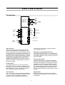
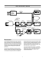
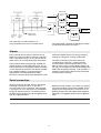
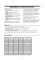
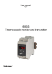
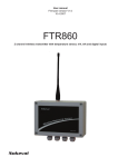
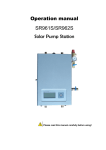
User manual 10.3.2008 V1.4 RMD681 8 channel transmitter DESCRIPTION RMD681 is an 8 channel measurement unit for temperature sensors and other electrical inputs. The unit has both analog and serial outputs. The analog output can be selected among the input channels using binary PNP inputs. Every channel has two alarm levels controlling two common alarm relays. The inputs are galvanically isolated from the outputs and the supply voltage, but not from each other. There is a 2+5 digit display and four push-buttons, that can be used to monitor the readings and to change the settings. The settings can also be edited from a personal computer using RS-485 serial connection. Protocols offered are Nokeval SCL and Modbus RTU. SPECIFICATIONS Inputs Pt100 Range Accuracy Thermal drift Sensor current -200…+700 °C 0.05% rdg + 0.25°C 0.02°C / °C 0.25 mA, multiplexed Ni100 Range Accuracy -60…+180 °C 0.05% rdg + 0.25°C Cu10 Range Accuracy -200…+260 °C 1°C KTY83 Range -55…+175 °C 0.02 °C/°C 0.05% rdg + 1°C + lin.error mV Ranges Accuracy Load ±55 and ±100 mV 0.1% rdg + 0.01 mV >1 Mohm V Ranges Accuracy Load 1V (-1…+1 V) 2.5V (-1…+2.5 V) 10V (-10…+10 V) 0.05% rdg + 0.01 V >1 Mohm mA Range Accuracy Load ±20 mA 0.008 mA 50…80 ohm Ohm Ranges PtXXX, NiXXX, CuXXX Range Same as Pt100, Ni100... Thermocouples TC B C D E G J K L N R S T Ambient comp Accuracy Common A/D conversion Speed range ±lin.error 400…1700°C ±0.3°C 0…2300°C ±0.5 0…2300°C ±1 -100…900°C ±0.2 1000…2300°C ±2 -160…950°C ±1 -150…1370°C ±0.5 -150…900°C ±0.5 0…1300°C ±0.1 0…1700°C ±0.5 0…1700°C ±0.5 -200…400°C ±1 Cable length Overvolt category 2 0…400 ohm 0…4000 ohm 0…40000 ohm 16 bits (±32767) Cycle time is (number of channels + 1) / 12 seconds. All channels in 1.4 seconds. Max 30 m (EMC) Not rated; input common mode potential may not exceed 50 VDC or 120 VAC with respect to ground Analog output Supply voltage Voltage Current mA output Range Accuracy Load 0…20 mA or less 0.008 mA 0…600 ohm V output Range Accuracy 0…10 V or less 0.005 V Common Source Channel select time Environment Oper. temperature Pollution class Direction Passive level Active level Load Cable length Weight Mounting Connectors Galvanic isolation Selecting the input channel to be displayed or for the analog output; can be read with serial comms PNP (active high), internal pull-downs. -0.5...1 V 3…30 V about 5 kohm Max 3 m (EMC) Baud rates Bits Max response time Reading all chs Min response time Termination EMC immunity EN 61326, Annex A EM field 61000-4-3, 10 V/m: criterion A. Burst 61000-4-4, any port, 2 kV: criterion B. Surge 61000-4-5, power supply, 1 kV line-to-line: criterion A. 61000-4-5, inputs: not applied (short-distance wires). 61000-4-5, serial and outputs: 1 kV line-to-ground: criterion B. Conducted RF 61000-4-6, any port, 3 V: criterion A (shielded cable used). RS-485 Nokeval SCL Modbus RTU 1200, 2400, 4800, 9600, 19200, 38400, 57600 SCL: 8N1 Modbus: 8E1, 8O1, 8N2 SCL: typ 3, max 65 ms Modbus: typ 5, max 15 ms (after changing settings, 300 ms for the next command) SCL: 110 ms @38400 baud Modbus: typ 28, max 38 ms 3.5 characters Jumper selectable: None or 110 ohm + 1 nF EMC emissions EN 61326 RF emissions CISPR 16 class B Alarms Response Relays Device unpowered 350 g 35 mm DIN rail 1.5 mm2, detachable Inputs together. Power supply and analog and serial output together. These groups isolated from each other. Regulations Serial connection Connection Protocols -10...+60 °C 1 Other Certain channel, externally selected channel, minimum, maximum, or serial comms < 40 ms Digital inputs Use 24 V ±15% < 100 mA Same as meas. cycle + definable delay 2 A, 250 VAC Relay 1 closed, 2 open. 3 INSTALLING Connections F 6 5 4 3 2 1 Input channels Conn C= 1, 2 Conn D= 3, 4 Conn E= 5, 6 Conn F= 7, 8 Channel select Device select Supply voltage +24 V Com Com 1 2 3 lsb B K msb A L + + Pt100 C 1 2 3 4 5 6 7 8 TC mA + 6 5 4 3 2 1 Com D0 (-) D1 (+) 0-10V Com 4-20 mA 6 5 4 3 2 1 + 2 1 Potent. eq. link RS-485 Analog out Alarm relay 2 Alarm relay 1 current input jumper must be closed inside the case near the connector. Input channels There is three terminals for each input channel: positive and negative input and the ground. The ground connections are connected together among the channels, but the positive and negative inputs are differential and can tolerate about 1 V above or below the ground. Potential equalisation is needed to keep the input voltages near the ground. Most simple way to guarantee this is to connect the negative input to ground (2-3 and 5-6). This is not applied to resistance measurements, that use all the three terminals. Resistance inputs (Pt100 and others) The negative end of the sensor is connected with two wires in terminals 2 and 3. The positive end is connected in terminal 1 with one wire. The sensors must be isolated. Thermocouple inputs The thermocouples are connected in terminals 1 and 2 (or 4 and 5), as in the figure. If the sensors are electrically isolated from the target, the sensor potential is recommended to be bound by linking terminals 2-3 (or 5-6). Instead, if there is several sensors connected to the same conducting target, the potential equalisation can be done with one wire connecting the target to terminal 3 or 6 at any channel. Voltage inputs The voltage inputs (mV or V) are connected in terminals 1 and 2 (or 4 and 5). In addition to that the terminals 2-3 and 5-6 are recommended to be linked together in order to equalise the potential. The current input jumper must be open. Current inputs The current input (mA) is connected in terminals 1 and 2 (or 4 and 5). In addition to that the terminals 2-3 and 5-6 are recommended to be linked together in order to equalise the potential. The Digital inputs Digital PNP inputs are used to select the input channel for the analog output (or the channel that is displayed). 4 Analog output Either mA or V output can be used. They can't be used at the same time (they do work but the other is very inaccurate). The analog output ground is the same as the power supply ground. Serial connection Serial connection RS-485 is available at connector B. Its ground is connected to the supply and analog output grounds. If the potential between serial devices is not equalized through the power network, it is recommended to connect their Common terminals together with an auxiliary wire. If this potential equalisation is not possible, then it is advisable to engage the RS-485 floating jumper inside the case, see Jumpers. D1 is the more positive terminal (Nokeval A or +). The maximum recommended distance is 1 km. The cable should be a twisted pair, wire gauge 0.5 mm minimum. Alarm relays The device is equipped with two relays capable to switch 250 VAC. If either of the relays is connected to a line voltage, the other must not be connected to low-voltage circuits. Relay 1 contacts are closed when no power is applied to the transmitter. Power supply Supply voltage 24 VDC is connected in connector L. 86 100 150 5 Jumpers Inside the case, there is one jumper next to each input channel connector. It has to be closed when using mA input, and else open. should be enabled in the first and last device on the RS-485 bus. When neither of these functios is desired, the jumper may be parked between the top pins of J5 and J6. In the middle card, there is a jumper marked ”2 wire”. It should be closed when there is no potential equalisation between the RS-485 devices. E.g. Nokeval 711 serial converter has no common terminal, so this jumper should be used. Next to that, there is an AC termination jumper J6, that To access the jumpers, prise a screwdriver between the bottom and top covers near the locking tabs at the case ends. Settings The settings can be done with either the front panel buttons or the serial connection. Using the buttons is described in chapter User interface, and the settings in chapter Settings. also a RS-485 connection to your computer. An inexpensive alternative is Nokeval DCS770 USBto-RS485 converter. Select the same communication parameters in each end before attempting to connect. See also chapter Settings. The PC software needed is called Mekuwin. It is free from Nokeval web site. To use it, you need 6 OPERATION Serial interface Digital inputs Digi Analog output Isens CJ1-2 A/D converter Sensor processing Scaling Lowpass filter Display 123.4 Comparator OR function among ch's Delay & NO/NC logic Rel Relay output + - Other channels Measurement The transmitter measures every active channel at a time. When all is done, the transmitter does one internal measurement, that means measuring the RTD sensor current or one of the four cold junction sensors. There is only one A/D converter, and it is connected to one channel at a time using semi conductor switches, along with the RTD current generators. the terminals 3 and 6 at every input channel. With resistance sensors, the third wire will do it, but with the other inputs the potential equalisation should be done as described in chapter Connections. If the wires are short, it may not be necessary. See also Differential in chapter Settings. The normal measurement speed is 12 channels per second. If there is 10 channels used, they are updated every second. Remember that there is one internal measurement in addition to the external measurements. The A/D input is differential, measuring only the difference between the positive and negative input terminal. However these voltages must be within 1 V of the input circuit ground, which is available at 7 Analog output and digital inputs RMD681 has one analog output. It can be selected to follow a selected input channel, or use the digital input to select the channel to be output. See Output/Source setting. For external channel selection, the device is equipped with 8 digital inputs of PNP type. A positive voltage (3-24 V) is active state. First four terminals (K1-K4) are used to select the input channel, that is used for the analog output. When these are passive (0 V), channel 1 is used. K1 is the least significant bit. If 8 channels is not enough, several RMD681's can be connected in parallel to one mA output. In this case, only one transmitter is activated at a time using the other digital inputs (K5-K8). When the binary word 0-15 at these terminals correspods to the Addr setting in Output menu, the analog output is activated. There is two ways to use this: If the terminals K1-K8 are connected in parallel in several transmitters and a different address is selected in every transmitter (Output/Addr), any transmitter can be activated using a binary word. Maximum number of transmitters is 16. 8 Conf menu > ^+* Item 1 Edit value * ^ v > > Item 2 * Save ^ ^ > Edit value * v Submenu v > Item 3 Undo Item 3.1 * Edit value * ^ v Item 3.2 The other way is to select address 1 in every transmitter and connect a enable line to every transmitter connector K5. Bringing a voltage to this terminal activates the output. Alarms Every channel has two alarms, and they can be either low or high level alarms. Alarms 1 operates relay 1 and alarm 2 relay 2. If any channel has an alarm active, the corresponding relay will activate. make the lowpass filter to give wrong, decaying reading for a long time, causing a false alarm. The alarm information from each channel is combined using ”OR logic”, meaning that the common alarm will be considered active, if the alarm is active on any channel. Before applying to the relay, the activation and deactivation delays are added and the polarity reversed, if NC operation is enabled. The Rel item in Monitor menu shows the real relay state (1=pulling). These channel alarms simply judge, whether the reading is above or below the alarm level. The A1 and A2 indicators on the display indicate the states on the channel being viewed. The alarms are taken from unfiltered reading. This is because the lowpass filter could work against the delay functions: a short but large input disturbance would Serial connection Serial command is received, then it is processed and finally a response is sent. To process a commend and to form a response, takes typically 3, maximum 15 ms on SCL protocol, except MEA SCAN can take up to 65 ms. The whole process for MEA SCAN 1 8 takes abt 120 ms @9600 baud and 70 ms @38400 baud. Modbus protocol is faster, since there is no need to format the readings to be human-readable. So the response time is typically 5 ms, maximum 15 ms. Reading all the inputs using Read Input Registers takes abt 70 ms @9600 baud and 20 ms @38400 baud. 9 USER INTERFACE Front panel Serial communication Internal or external fault detected Common alarms Configuration state Channel Rel1 Rel2 Serial Fault Conf A1 A2 Channel alarms M Nokeval RMD series * Normal state After the power-up a channel number and a reading is displayed. Depending on the Scan setting, a fixed channel is diplayed, or the channels are scanned. The channel can be selected manually using ^v buttons, and after the last channel minimum and maximum readings and the average are displayed. when a serial message is received at correct address. Fault indicator is lit when a sensor is broken or there is internal fault. Conf is lit when in configuration state. These indicators are not dependent on the channel selected. A1 and A2 indicate, whether there is active alarms at the selected channel. They blink when an alarm level is shown in operator menu. M is not used. Rel1 and Rel2 indicators show the real state of the alarms: active or not active. Serial indicator is lit Operator menu The alarm levels can be changed without entering the configuration state. Use > button to select the function: Alarm level 1 – Alarm level 2 – Normal state. Blinking A1 or A2 indicates that an alarm level is displayed. In this state, the level can be changed by pressing first ^ or v and then ^v>. When done, push *. If common alarm level is used among the channels (Alarms / Cmn levels), the channel display will show Co (=Common) when an alarm level is displayed. If an automatic display scan mode is used (General/Scan), it has to be interrupted temporarily. Just push ^ or v. 10 Configuration state Press * and ^ simultaneously two seconds to enter the configuration state. When entered, the Conf led will light. If configuration password is set, you will need to enter it (Cod.0 displayed). In case the password is not known, switch the power off, hold * and > keys pressed and switch the power on again – PWDC is displayed briefly. This will also set the serial settings to their default values. To edit the setting, push > to start editing, and * to get back to the menu. How to edit, see section Editing. The menu is organizated hierarchically. You can enter General, Input, Output, Alarms, and Serial submenus by selecting them with ^v keys, and entering the submenu with > key. See the menu chart in chapter Settings. The main level of the configuration menu is shown. You can select among menu items using ^v keys. When all settings are done, exit from the menu with * key. Two options are shown: Save to keep the settings made, and Undo, to discard all changes. Select Save or Undo and push >. Editing Most data types are edited with simply ^v keys, finally exiting with * key. Floating point values, such as scaling and the lopass filter, are edited with ^v> keys: select digit to edit (blinking) with > and change it with ^v. When the decimal point is blinking, it can be moved with ^v. The first digit can be replaced with a minus sign. To set a password, push ^ to select Set (means password will be used), then push > to enter the new password. Cod.0 is shown. The password is a sequence of six keypresses using all the four keys. Enter the same password twice; if they match, Set is shown again and you can exit with *. If they didn’t match, Off is shown. Redo from start. To disable a password, push v to select Off and exit with *. Monitoring state Monitoring can be used to examine some internal readings. Use the monitor mode in the PC software or the built-in monitor mode. CJ1-C2: internal cold junction temperatures. Digi inputs: digital inputs as an integer 0- 255. The built-in monitoring is started by pressing * and v together. Select the item using ^v keys, and exit with *. Out: analog output value mA or V. Rel: alarm relays 0=none, 1=Rel1, 2=Rel2, 3=both active. Cycle time: measurement cycle time in seconds. Items Last item is Diag, that can be used to see diagnostic messages. Push >. If nothing happens, then there is no messages. If happens, try ^v to see if there is several messages. Exit with *. In1-In8: latest readings. Min, Max: minimum and maximum reading on channels 1-8. Avg: average of the channels. Ext: ”ext” channel controlled by serial RMD681 has two messages: Sensor Fault: some channel has improper connection, overranging or a broken sensor or wires. AD Error: A/D converter is not working. Needs service. communications; see Out\Source Isens: measured resistance sensor measurement current, normally about 0.25 mA. 11 SETTINGS General Input Output Alarms Serial General submenu General submenu has settings that do not belong to the other groups. Common Ch1 Ch2 Alm1 Alm2 Ch16 Scan Automatic changing of the displayed channel. • Off: The channel is changed only manually using buttons ^v. • All: All the active channels are scanned, at one second interval. • Alarming: Like All, but if any channel has active alarm, only alarming channels are scanned. • Mux: The channel to be displayed is selected using digital inputs K1-K4, like the analog output. If the Output/Source setting is set to Mux, the Output/Addr must correspond to the digital input at K5-K8, otherwise dashes ”--” are shown in the channel display and the reading display is empty.. Differential Internal grounding of the differential inputs. Not applicable to resistance inputs, like Pt100. • No: The transmitter uses a semiconductor switch to groud the negative terminal of the channel being measured. • Yes: The inputs are differential (or floating) and the potential equalisation must be done externally. Pullup Sensor/wire break sensing. If enabled, a weak current is fed to thermocouple sensors to detect breaks. The scanning can be always stopped temporarily by pushing ^ or v in the normal state. Then the channels can be selected manually using ^v buttons and alarm levels viewed using > button. Automatic scanning is activated again if the buttons are not touched for 10 seconds, or ^ and v are pushed together. Input/Ch1-Ch8 submenus Sensor Input range and sensor selection. • Off: Channel not used. It is recommended to set unused channels off, in order to speed up the measurement cycle. • 55mV, 100mV, 1V, 2.5V, and 10V: Voltage inputs. Can measure also negative voltage, however 2.5V range reaches only -1 V. The reading is in millivolts or volts according to the name of the range. • 20mA and 50mA: Current inputs. Can measure also negative current. The jumper inside the case has to be closed. • 400ohm, 4000ohm, and 40000ohm: Resistance inputs. The resistor is connected in three-wire connection. The reading in ohms. • Pt, Ni, Cu, and KTY83: Resistance thermometers (RTD's). The nominal resistance is set in R0 (see below). The reading is in celsius. • TcB-TcT: Thermocouples. The result is in celsius. CfCode Selecting password for the settings. If enabled, the configuration menu can not be entered anymore without knowing the password. How to enter the password using the front panel, see chapter User interface. Input submenu Input submenu contains the input settings. It is further divided in Common and Ch1-Ch8 submenus. Input/Common submenu Speed Mesurement speed selection. Speed 1 is intended for normal use, and the specifications are valid for that. The higher speeds will increase noise. R0 The nominal resistance of a resistive temperature sensor. With Pt and Ni sensors, this is the resistance at 0°C, e.g. Pt100 R0=100. With Cu and KTY83, the nominal resistance is given at 25°C. If the real resistance of the sensor at the nominal 12 temperature is known, it can be fed here, in order to cancel the sensor error. Level Alarm level. If the Cmn Levels setting in Alarms submenu is on, these channel-specific level settings are hidden and replaced with one common setting in Alarms submenu. Lopass First-order lowpass filter for the reading. Will attenuate noise and disturbances. Set time constant (to 63% of step change) in seconds, or 0 to disable. There is no hysteresis function in the alarms. It is replaced with user-selectable delays, see Alarms menu. Dec The number of digits after the decimal point to be displayed. Can be set negative, to round the corresponding number of last digits to zero. In addition, this defines the decimal point location to the Modbus 16 bit integer readings (input regs 1000-1015). Examples how 123.45678 is rounded: Dec=2: ”123.45” Dec=0: ”123” Dec=-2: ”100” Output submenu Analog output settings. Source Where the output is taken from: • Mux: Multiplexing, selecting the channel using the digital PNP inputs. • Single: Fixed channel, see Ch below. • Min: Minimun reading among input channels 18. • Max: Maximum reading. • Avg: Average reading. • Ext: Ext channel, controlled by serial communications (SCL OUT or Modbus Holding 2000). Pts Number of scaling points. The scaling means converting the reading to represent some other (engineering) reading. The scaled value is used on the display, serial output, analog output, and alarms. • 0: No scaling. • 1: One point offset correction. The reading corresponding to Mea1 is scaled to be Sca1 when displayed, using appropriate offset value. • 2: Two point scaling. Readings from Mea1 to Mea2 are scaled to be Sca1 to Sca2 on the display. Any values can be used, these have not to be the end points. Ch Fixed input channel selection. Visible only when Source=Single. Select input channel 1-8, that is used to control the analog output. Mea1, Sca1, Mea2, and Sca2 Scaling points. Visibility of these settings depend on the Pts setting. Unscaled reading Mea1 is converted to Sca1, and Mea2 to Sca2. Addr Multiplexing address. Visible only when Source=Mux. Select address 0-15. The analog output is active only when the digital inputs K5-K8 are controlled to correspond to this address. Alm1 and Alm2 Submenus for alarm settings on each channel. Range Analog output range mA or V. Rdg1, Out1, Rdg2, and Out2 Output scaling. Reading Rdg1 on display corresponds to output signal Out1 (in mA or V), and Rdg2 to Out2. These have not to be the end points, since the transmitter is able to extrapolate. Input/Ch1/Alm submenus Every input channel has two alarm functions. They are configured in submenus Alm1 and Alm2 below each input channel settings. Some more settings concerning the alarms are in the Alarms submenu in the Conf main level. Alarms submenu Type Alarm type: • Off: Alarm not used. • Lo: Low level alarm. The alarm is activated when the scaled reading on this channel goes below the alarm level. • Hi: High level alarm. Common settings of the alarms. Cmn levels • No: Every channel has alarm limits of its own (e.g. Input/Ch1/Alm1/Level). • Yes: Common alarm levels are used on all channels. The levels are defined in this menu, 13 items Lev1 and Lev2. However the alarms has to be switched on on every channel separately. Serial submenu Lev1, Lev2 Common alarm levels when Cmn levels is enabled. Serial connection settings. Note that the changes here do not affect until the configuration state is exit. ActDelay, DeaDelay Alarm activation and deactivation delays. An alarm must be continuously active for the time specified in ActDelay in order to cause a real, common alarm. The functional diagram in chapter Operation clarifies this. Protocol Serial protocol: • SCL: Nokeval SCL protocol. The description of this protocol can be obtained from Nokeval www pages, and the commands are listed in chapter SCL protocol. • Modbus: Modbus RTU protocol. The registers and data representation are described in chapter Modbus protocol. The delay times are given in seconds. The maximum delay time is 3495 seconds. Note that the alarm is taken from unfiltered reading, so these delays are the only protection against false alarms. Address Serial bus address. Valid choices for SCL are 0123 and for Modbus 1-247. NC1, NC2 Inverting the relay operation. Affects only the coils of the relays, but not the LED indicators. • No: Normal operation, normally open: the relay pulls when an alarm is active. • Yes: Inverse operation, normally closed: the relay releases when an alarm is active. Baud Baud rate selection. Options 1200, 2400, 4800, 9600, 19200, 38400, and 57600 bits per second. Bits Parity and stop bits. Visible with Modbus only; SCL uses always 8N1. Options 8E1 (recommended), 8O1, 8N2. 14 SCL PROTOCOL A more detailed description of the Nokeval SCL protocol can be downloaded from Nokeval www pages http://www.nokeval.com/ under the data acquisition pages. MEA SCAN 1 8 Returns the readings on channels 1-8 separated by one space. See MEA CH for data representation. RMD681 understands the following SCL commands: OUT CH 1 23.45 Writes to the ”Ext” channel a value of 23.45. The analog output can be set to follow the Ext channel by selecting Out/Source=Ext. TYPE ? Returns the model name and software version ”RMD681 V1.4” without the quotation marks. DI CH 1 ? Returns the state of the digital input 1 (connector K1). The answer is either ”0” or ”1” without the quotation marks. SN ? Returns the serial number, e.g. ”A123456”. MEA CH 1 ? Returns the scaled reading on channel 1. Channels 1-8 can be read this way. Moreover: • channels 9 and 10 = minimum ja maximum • channels 11 and 12 = average and Ext • channels 13 and 14 = cold junction temperatures DI SCAN 1 8 Returns the states of the digital inputs separated with a space, e.g. ”1 1 0 0 1 1 1 1”. The digital input K1 is returned first. MN xxxxx Commands used by Mekuwin configuration software. The response consists of characters -.0123456789. The scientific notation (1E3) is not used. In case of invalid reading, the response consists of dashes ”------”. With over/underflow, the response is ”^^^^^” or ”uuuuu”. The reading is always represented with six significant digits (except negative readings with five), e.g. pi would be represented ”3.14159”. After power-up, before the first reading is obtained, the transmitter will return NAK 0 message to MEA commands, in order to prevent logger software from logging invalid readings. 15 MODBUS PROTOCOL Supported commands: • 2 Read Discrete Inputs: reading the digital inputs. • 3 Read Holding Registers: reading the settings. • 4 Read Input Registers: reading the input readings. • 6 Write Single Register: changing the settings and the Ext channel. • 16 Write Multiple registers: changing the settings. • 17 Report Slave ID: checking the device type. • 109 Meku: Mekuwin configuration software uses this. non-voltatile EEPROM memory immediately. It might take several dozens of milliseconds for the transmitter to respond to the next command. The maximum length of the command is 150 bytes. The maximum length of the response is the same. This sets the limit to number of registers with commands 3, 4, and 16. The command 17 will return 0x11 <byte count> 0x00 0xFF, followed with ”RMD681 V1.3 A123456”, for example. When the serial connection settings are changed, the changes do not affect until the transmitter is powered down. This is to prevent breaking the connection while making the changes. When the settings are changed by writing to a Holding register, the settings are changed to the Data types • • • • • • BOOL: Off/on setting. Only the least significant bit is used. BYTE: One byte setting. Only the lower word of the Modbus register is used. WORD: 16-bit setting. ENUM: Option list setting. The options listed in section Enum tables. CODE: Password 12 bits. 0=not used. FLOAT: 32-bit floating point number IEEE 754. Least significant word first (LSWF, little-endian). Within one Modbus register, the data is represented the most significant byte first (MSBF, big-endian). Input registers Register 0..1 2..3 4..5 6..7 8..9 10..11 12..13 14..15 16..17 18..19 20..21 22..23 24..25 26..27 Integer register 1000 1001 1002 1003 1004 1005 1006 1007 1008 1009 1010 1011 1012 1013 Name In1 In2 In3 In4 In5 In6 In7 In8 Min Max Avg Ext Isens CJ1 Type Values FLOAT FLOAT FLOAT FLOAT FLOAT FLOAT FLOAT FLOAT FLOAT FLOAT FLOAT FLOAT FLOAT FLOAT Signed Signed Signed Signed Signed Signed Signed Signed Signed Signed Signed Signed Unsigned Signed 16 28..29 30 31..32 33 34..35 1014 1015 1016 1017 1018 CJ2 Digi inputs Out Rel Cycle time FLOAT BYTE FLOAT BYTE FLOAT Signed Unsigned 0...255 Signed Bits 0...3 Unsigned The channel 1-8 readings can also be read as 16-bit signed integers in registers 1000-1018. The readings have as many digits after the decimal points as is set with the Dec setting in the settings of that channel. E.g. Dec=1: divide the integer by 10 (=101) to get the reading. Holding registers The registers 0..1999 contain the configuration settings. Register pair 2000..2001 is the Ext register that can be used to control the analog output. The input readings can be accessed through Holding registers 5000 onwards, although using Input registers is recommended. Register 0 1 2 3 4 5 6..7 8..9 10 11 12..13 14..15 16..17 18..19 20 21..22 23 24..25 26..172 173 174 175 176 177..178 179..180 181..182 183..184 185 186..187 Name Conf\General\Scan Conf\General\CfCode Conf\Input\Common\Speed Conf\Input\Common\Differential Conf\Input\Common\Pullup Conf\Input\Ch1\Sensor Conf\Input\Ch1\R0 Conf\Input\Ch1\Lopass Conf\Input\Ch1\Dec Conf\Input\Ch1\Pts Conf\Input\Ch1\Mea1 Conf\Input\Ch1\Sca1 Conf\Input\Ch1\Mea2 Conf\Input\Ch1\Sca2 Conf\Input\Ch1\Alm1\Type Conf\Input\Ch1\Alm1\Level Conf\Input\Ch1\Alm2\Type Conf\Input\Ch1\Alm2\Level Type ENUM CODE ENUM BOOL BOOL ENUM FLOAT FLOAT BYTE BYTE FLOAT FLOAT FLOAT FLOAT ENUM FLOAT ENUM FLOAT Values See table E1 The register address of the other channels is obtained by adding 21*(Ch-1) to the channel 1 settings. Conf\Output\Source Conf\Output\Ch Conf\Output\Addr Conf\Output\Range Conf\Output\Rdg1 Conf\Output\Out1 Conf\Output\Rdg2 Conf\Output\Out2 Conf\Alarms\Cmn levels Conf\Alarms\Lev1 ENUM BYTE BYTE ENUM FLOAT FLOAT FLOAT FLOAT BOOL FLOAT See table E5 Unsigned 1...8 Unsigned 0...15 See table E6 Signed Signed Signed Signed 17 See table E2 See table E3 Unsigned Unsigned Signed -3...4 Unsigned 0...2 Signed Signed Signed Signed See table E4 Signed See table E4 Signed Signed 188..189 190..191 192..193 194 195 196 197 198 199 2000..2001 2002 5000..5035 6000..6018 Conf\Alarms\Lev2 Conf\Alarms\ActDelay Conf\Alarms\DeaDelay Conf\Alarms\NC1 Conf\Alarms\NC2 Conf\Serial\Protocol Conf\Serial\Address Conf\Serial\Baud Conf\Serial\Bits Ext Ext In1.. In1 FLOAT FLOAT FLOAT BOOL BOOL ENUM BYTE ENUM ENUM FLOAT WORD FLOAT WORD Discrete input registers The discrete input registers 0-7 correspond to the digital inputs K1-K8. Enum tables Table E1 Value Scan 0 Off 1 All 2 Alarming 3 Mux Table E2 Value Speed 0 1 normal 1 2 2 3 3 4 fastest Table E3 Value Sensor 0 Off 1 55mV 2 100mV 3 1V 4 2.5V 5 10V 6 20mA 7 50mA 8 400ohm 9 10 11 12 13 14 15 16 17 18 19 20 21 22 23 24 25 26 4000ohm 40000ohm Pt Ni Cu KTY83 TcB TcC TcD TcE TcG TcJ TcK TcL TcN TcR TcS TcT Table E4 Value Type 0 Off 1 Lo 2 Hi 18 Signed Unsigned Unsigned See table E7 Unsigned 0...255 See table E8 See table E9 Signed Signed Signed Table E5 Value Source 0 Mux 1 Single 2 Min 3 Max 4 Avg 5 Ext Table E6 Value Range 0 mA 1 V Table E7 Value Protocol 0 SCL 1 Modbus Table E8 Value Baud 0 1200 1 2400 2 4800 3 9600 4 19200 5 38400 6 57600 Table E9 Value Bits 0 8E1 1 8O1 2 8N2 19