1
ADPRO Presidium by
Xtralis
(includes Presidium-Mini)
Installation and
User Manual
March 11, 2010
Part 201975.05
ADPRO Presidium by Xtralis
Installation and User Manual
Disclaimer
The contents of this document are provided on an "as is" basis. No representation or warranty (either express or implied) is made as to the
completeness, accuracy or reliability of the contents of this document. The manufacturer reserves the right to change designs or
specifications without obligation and without further notice. Except as otherwise provided, all warranties, express or implied, including
without limitation any implied warranties of merchantability and fitness for a particular purpose are expressly excluded.
Intellectual Property and Copyright
This document includes registered and unregistered trademarks. All trademarks displayed are the trademarks of their respective owners.
Your use of this document does not constitute or create a licence or any other right to use the name and/or trademark and/or label.
This document is subject to copyright owned by Xtralis AG ("Xtralis"). You agree not to copy, communicate to the public, adapt, distribute,
transfer, sell, modify or publish any contents of this document without the express prior written consent of Xtralis.
General Warning
This product must only be installed, configured and used strictly in accordance with the General Terms and Conditions, User Manual and
product documents available from Xtralis. All proper health and safety precautions must be taken during the installation, commissioning
and maintenance of the product. The system should not be connected to a power source until all the components have been installed.
Proper safety precautions must be taken during tests and maintenance of the products when these are still connected to the power source.
Failure to do so or tampering with the electronics inside the products can result in an electric shock causing injury or death and may cause
equipment damage. Xtralis is not responsible and cannot be held accountable for any liability that may arise due to improper use of the
equipment and/or failure to take proper precautions. Only persons trained through an Xtralis accredited training course can install, test and
maintain the system.
Liability
You agree to install, configure and use the products strictly in accordance with the User Manual and product documents available from
Xtralis.
Xtralis is not liable to you or any other person for incidental, indirect, or consequential loss, expense or damages of any kind including
without limitation, loss of business, loss of profits or loss of data arising out of your use of the products. Without limiting this general
disclaimer the following specific warnings and disclaimers also apply:
Fitness for Purpose
You agree that you have been provided with a reasonable opportunity to appraise the products and have made your own independent
assessment of the fitness or suitability of the products for your purpose. You acknowledge that you have not relied on any oral or written
information, representation or advice given by or on behalf of Xtralis or its representatives.
Total Liability
To the fullest extent permitted by law that any limitation or exclusion cannot apply, the total liability of Xtralis in relation to the products is
limited to:
(i) in the case of services, the cost of having the services supplied again; or
(ii) in the case of goods, the lowest cost of replacing the goods, acquiring equivalent goods or having the goods repaired.
Indemnification
You agree to fully indemnify and hold Xtralis harmless for any claim, cost, demand or damage (including legal costs on a full indemnity
basis) incurred or which may be incurred arising from your use of the products.
Miscellaneous
If any provision outlined above is found to be invalid or unenforceable by a court of law, such invalidity or unenforceability will not affect the
remainder which will continue in full force and effect. All rights not expressly granted are reserved.
FCC Compliance Statement
This equipment has been tested and found to comply with the limits for a Class B digital device, pursuant to part 15 of the FCC Rules.
These limits are designed to provide reasonable protection against harmful interference in a residential installation. This equipment
generates, uses and can radiate radio frequency energy and, if not installed and used in accordance with the instruction, may cause
harmful interference to radio communications. However, there is no guarantee that interference will not occur in a particular installation. If
this equipment does cause harmful interference to radio or television reception, the user is encouraged to try to correct the interference by
one or more of the following measures; re-orientate or relocate the receiving antenna, increase the separation between the equipment and
receiver, connect the equipment to a power outlet which is on a different power circuit to the receiver or consult the dealer or an
experienced radio/television technician for help.
Document Conventions
The following typographic conventions are used in this document.
Doc. 12384_05
Convention
Description
Bold
Used to denote: emphasis
Used for names of menus, menu options, toolbar buttons
Italics
Used to denote: references to other parts of this document or other documents. Used for the result of an
action
i
Installation and User Manual
ADPRO Presidium by Xtralis
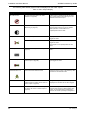
The following icons are used in this document
Convention
Description
Caution: This icon is used to indicate that there is a danger to equipment. The danger could be loss of data,
physical damage, or permanent corruption of configuration details.
Warning: This icon is used to indicate that there is a danger of electric shock. This may lead to death or
permanent injury.
Warning: This icon is used to indicate that there is a danger of inhaling dangerous substances. This may
lead to death or permanent injury.
Information: This icon is used to indicate that the particular feature or action is not available when using the
Presidium Mini product.
Apple m DNSResponder Licence Agreement
Presidium uses Apple mDNSResponder open source software. This software is covered by the Apple Public Source Licence. PApple
mDSNSResponder software is available from Apple website: http://developer.apple.com/opensource/internet/bonjour.html
The ADPRO Product Installation and Upgrade DVD contains a copy of all distribution licences relevant to Presidium.
Tradename statement
Xtralis ADPRO is a registered trademark of Xtralis AG Pty Ltd.
Lightning or Related Voltage Surges
Damage or malfunction caused by lightning or related voltage surges may be excluded from the manufacturer’s warranty at the
manufacturer’s discretion.
Safety Procedures
Installations in the United States of America and Canada
For systems installed in the United States of America and Canada the following requirement is applicable:
All equipment installations are required to be in accordance with the National Electrical Code (NEC) ANSI/NFPA 70 and the Canadian
Electrical Code (CEC) Part 1, CAN/CSA C22.1.
If the power cord is not supplied with the Presidium select the proper power cord according to your local national electricity code.
USA: use a UL listed type SVT or SJT detachable power cord.
Canada: use a CSA certified detachable power cord.
Radio Interference
The Presidium complies with Part 15 of the FCC Rules. Operation is subject to the following two conditions: (1) This device may not cause
harmful interference, and (2) this device must accept any interference received, including interference that may cause undesired operation.
The Presidium complies with the electromagnetic emission limit requirements of AS/NZS CISPR22 and EN55022 Class A. In a domestic
environment this product may cause radio interference in which case the user may be required to take adequate measures.
Internal Lithium Battery
Caution:
ii
The Presidium contains an internal lithium battery.
There is danger of explosion if the battery is incorrectly replaced.
The battery is not user replaceable and can only be replaced by Xtralis or their Authorised Service Representative.
Doc. 12384_05
ADPRO Presidium by Xtralis
Installation and User Manual
Compliance of Power Cord
Caution:
If the power cord supplied with the Presidium or the Presidium Mini plug pack is not suitable for your local power
connection, do not modify the cord or plug pack. Please purchase a power cord that has the safety approvals
appropriate for your country.
Connection to Other Equipment
Caution:
All interface ports on the Presidium must be only connected to other equipment or systems that are Safety Extra Low
Voltage (SELV) rated. Failure to do so will invalidate the electrical safety approval and may cause injury or loss of life
Contact Us
The Americas +1 781 740 2223 Asia +852 2916 8894 Australia and New Zealand +61 3 9936 7000
Continental Europe +32 56 24 19 51 UK and the Middle East +44 1442 242 330
www.xtralis.com
Doc. 12384_05
iii
Installation and User Manual
ADPRO Presidium by Xtralis
Declaration of Conformity
Manufacturer's Name:
Manufacturer's Address:
Xtralis AG Pty Ltd
4 North Drive,
Virginia Park
236-262 East Boundary Road
Bentleigh East
VIC 3165
Australia.
Authorised EU Representative:
Xtralis (UK) Ltd,
Vision House,
Focus 31, Mark Road
Hemel Hempstead
Hertfordshire HP2 7BW, UK
declares, that the product(s):
Product Name:
Model Number:
ADPRO Presidium by Xtralis Intelligent Video System
PDM-xx
VM-15
Product Options:
All
Product Name:
Model Number:
ADPRO Presidium-Mini Intelligent Video System
PDM-Mini
meet the Standards detailed below.
EMC Emissions
EN55022:1998 (CISPR 22:1997) + A1, A2, AS/NZS CISPR 22:2006 Class A
Conducted and radiated emissions.
FCC Part 15 Class A Conducted and radiated emissions.
EN 61000-3-2:2000 + A1 + A2 Current harmonic emissions.
EN 61000-3-3:1995 + A1 Voltage fluctuations and flicker.
EMC Immunity
EN 50130-4:1995 +A1 + A2 Alarm systems immunity.
Safety
EN 60950-1:2001 Safety of Information Technology Equipment
IEC 60950-1:2001 1991 Safety of Information Technology Equipment
Supplementary Information
The products listed comply with the requirements of the Low Voltage Directive 2006/95/EC (where applicable) and the
EMC Directive 2004/108/EC and carries the CE marking accordingly. The products were tested in a typical configuration.
The CE Mark first applied in 2002.
iv
Doc. 12384_05
ADPRO Presidium by Xtralis
Installation and User Manual
Contents
1 Introduction ......................................................................................................................................1
1.1 Features of the Presidium ..................................................................................................1
1.2 Unique Features of Presidium Mini ...................................................................................1
1.3 Installation Steps ................................................................................................................2
2 Design Guide ....................................................................................................................................3
2.1 Introduction .........................................................................................................................3
2.1.1 Purpose .................................................................................................................... 3
2.1.2 Scope .......................................................................................................................3
2.1.3 Intended Audience ...................................................................................................4
2.1.4 Other Resources ......................................................................................................4
2.2 Quick Guide .........................................................................................................................4
2.3 The Role of Security ...........................................................................................................5
2.3.1 ADPRO Solutions ....................................................................................................5
2.3.2 Presidium - an ADPRO Solution ..............................................................................5
2.4 Presidium System Concept ................................................................................................6
2.4.1 Operational Concept ................................................................................................6
2.4.2 Basic Parameters .....................................................................................................6
2.5 System Design .................................................................................................................... 6
2.5.1 Preliminary Information ............................................................................................7
Assess Site Plans ....................................................................................................7
Discuss Requirements .............................................................................................7
Recommendations ...................................................................................................7
2.5.2 Site Survey ...............................................................................................................7
Detailed Site Plan ....................................................................................................8
Site Images ..............................................................................................................8
Clarify Requirements ............................................................................................. 10
2.5.3 System Hardware .................................................................................................. 11
Camera Selection and Location ............................................................................. 11
Other Detectors Selection and Location ................................................................ 15
PIR Alignment ........................................................................................................ 17
PIR Termination ..................................................................................................... 18
Camera/PIR Alignment .......................................................................................... 19
Illumination Requirements ..................................................................................... 19
Equipment Room ................................................................................................... 20
Monitoring Equipment ............................................................................................ 21
2.6 System Installation ........................................................................................................... 22
2.6.1 Camera Installation ................................................................................................ 22
Alignment ............................................................................................................... 22
Installation Hints ..................................................................................................... 23
Interference Caused by High Voltage or Ground Loops ........................................ 23
Installation Adjacent to Roads ............................................................................... 23
2.6.2 PIR Installation ....................................................................................................... 23
Alignment ............................................................................................................... 23
2.6.3 Instrument Racks and Cablings ............................................................................. 24
2.7 Site Commissioning .......................................................................................................... 25
2.7.1 Presidium Configuration ......................................................................................... 25
2.7.2 Performance Assessment ...................................................................................... 25
Detection Tests ...................................................................................................... 25
Soak Tests ............................................................................................................. 26
2.7.3 System Tests ......................................................................................................... 26
2.7.4 Recording System Configuration ........................................................................... 26
Doc. 12384_05
Installation and User Manual
ADPRO Presidium by Xtralis
2.8 Site Maintenance ............................................................................................................... 26
2.8.1 Routine Maintenance ............................................................................................. 27
2.8.2 Routine Site Maintenance ...................................................................................... 27
2.8.3 Routine Equipment Maintenance ........................................................................... 28
2.8.4 Routine Detection Tests ........................................................................................ 28
2.8.5 Maintenance to Regulatory Requirements ............................................................ 28
3 Presidium Connectors ................................................................................................................... 29
3.1 Presidium ........................................................................................................................... 29
3.2 Presidium Mini .................................................................................................................. 30
3.3 Power Connection ............................................................................................................ 32
3.3.1 Presidium ............................................................................................................... 32
3.3.2 Presidium Mini ....................................................................................................... 32
3.4 Earthing Screw .................................................................................................................. 32
3.5 Video Connections ........................................................................................................... 32
3.5.1 Inputs ..................................................................................................................... 32
3.5.2 Outputs .................................................................................................................. 33
3.6 Alarm Inputs ...................................................................................................................... 35
3.7 Isolation ............................................................................................................................. 36
3.8 Alarm Outputs ................................................................................................................... 37
3.9 General I/O Connector ...................................................................................................... 37
3.9.1 Access/Secure Input .............................................................................................. 38
3.9.2 Fault Relay ............................................................................................................. 39
3.9.3 General Alarm Relay Output .................................................................................. 40
3.10 Network Communications .............................................................................................. 40
3.10.1 Presidium ............................................................................................................. 40
3.10.2 Presidium Mini ..................................................................................................... 40
3.10.3 Network Connector LEDs .................................................................................... 40
3.11 Status LEDs ..................................................................................................................... 41
4 Installation / Configuration ............................................................................................................ 43
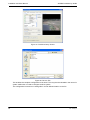
4.1 Unpacking .......................................................................................................................... 43
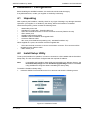
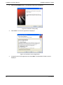
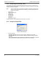
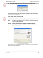
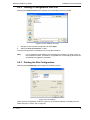
4.2 Install Setup Utility ............................................................................................................ 43
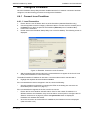
4.3 Configure the PC Network Connections ......................................................................... 45
4.4 Configure Presidium ......................................................................................................... 47
4.4.1 Connect to an Presidium ....................................................................................... 47
Presidium (standard) ............................................................................................. 48
Presidium Mini ....................................................................................................... 49
4.4.2 Setup Utility No Activity Timer ............................................................................... 50
4.4.3 Using the Setup Utility ........................................................................................... 50
4.4.4 System Status ........................................................................................................ 53
4.4.5 Configure Channels ............................................................................................... 54
General Setup ........................................................................................................ 54
Camera Calibration ................................................................................................ 56
Areas ..................................................................................................................... 57
Trigger Area Properties ......................................................................................... 58
Detection Parameters ............................................................................................ 60
Alarm Behaviour .................................................................................................... 63
Video Monitoring .................................................................................................... 65
4.4.6 Network Tab .......................................................................................................... 66
Device Name ......................................................................................................... 66
IP Address Configuration ....................................................................................... 66
4.4.7 High Level Interface Tab ........................................................................................ 67
Doc. 12384_05
ADPRO Presidium by Xtralis
Installation and User Manual
4.4.8 Security Tab ........................................................................................................... 68
Access/Secure Input Type ..................................................................................... 68
Authentication ........................................................................................................ 68
Default Settings ...................................................................................................... 69
4.4.9 Status Tab ..............................................................................................................69
4.5 Saving the Site Records ................................................................................................... 69
4.5.1 Saving a Configuration to File ................................................................................ 69
4.5.2 Loading a Configuration from File .......................................................................... 71
4.5.3 Printing the Site Configuration ............................................................................... 71
4.5.4 Upgrading Presidium Software .............................................................................. 72
4.6 Troubleshooting ................................................................................................................ 73
4.6.1 Detection Problems ................................................................................................ 73
4.6.2 IP Address Forgotten ............................................................................................. 73
4.6.3 Presidium Will Not Connect ................................................................................... 73
Presidium Appears in List of Local Units ................................................................ 73
Presidium Does Not Appear in List of Local Units ................................................. 74
4.6.4 Password Forgotten ............................................................................................... 74
4.6.5 HLI Connection to FastTrace Fails to Operate ...................................................... 75
4.6.6 Presidium Setup Utility cannot be Started ............................................................. 75
5 Connection to ADPRO FastTrace / FastTx / FastTrace-R by Xtralis .......................................... 77
5.1 Entering the FastTrace / FastTx / FastTrace-R Setup Screen ....................................... 79
5.2 Presidium Inputs ............................................................................................................... 80
5.2.1 Presidium Input Settings ........................................................................................ 81
Presidium Input Name ........................................................................................... 81
Presidium Input Camera View Style ....................................................................... 81
Camera Behaviour Setup ....................................................................................... 81
5.3 Advanced Communication Properties ............................................................................ 82
5.3.1 Presidium High Level Interface Properties ............................................................. 83
5.4 IP Address Requirements ................................................................................................ 83
6 Connection to a Third-Party DVR ................................................................................................. 85
7 Adding a VM15 Module .................................................................................................................. 87
8 Specifications ................................................................................................................................. 89
Appendix A False and Nuisance Alarms ......................................................................................... 91
Appendix B Site Survey Checklist ................................................................................................... 93
Appendix C Example Site Plan ........................................................................................................ 95
Appendix D System Design and Equipment Checklist .................................................................. 97
Appendix E Camera / Lens Selection .............................................................................................. 99
Appendix F Commissioning Checklist .......................................................................................... 101
Appendix G Site Detection Tests ................................................................................................... 103
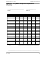
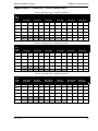
Appendix H Site Maintenance Tables ............................................................................................ 105
Appendix I Installation Quick Reference ....................................................................................... 107
Appendix J Presidium Do’s and Don’ts ........................................................................................ 109
Doc. 12384_05
Installation and User Manual
ADPRO Presidium by Xtralis
List of Figures
Figure 1: Suitable/Unsuitable Perimeter Conditions .............................................................................. 9
Figure 2: Suitable/Unsuitable Area Detection Scenes ......................................................................... 10
Figure 3: Required Video Signal .......................................................................................................... 11
Figure 4: Camera Dead Zone .............................................................................................................. 13
Figure 5: Camera Dead Zone Coverage.............................................................................................. 13
Figure 6: Recommended Presidium Pole Installation .......................................................................... 14
Figure 7: Presidium Pole Front View.................................................................................................... 15
Figure 8: FOV of Curtain PIR with Camera.......................................................................................... 16
Figure 9: FOV of Wide angle PIR with Camera ................................................................................... 16
Figure 10: Camera/PIR Mounting Details ............................................................................................ 16
Figure 11: Camera/PIR Dead Zone Comparison ................................................................................. 17
Figure 12: Optimal PIR Angle .............................................................................................................. 17
Figure 13: PIR Alignment on Fenceline ............................................................................................... 18
Figure 14: Example PIR Barrier ........................................................................................................... 18
Figure 15: Camera/PIR Alignment ....................................................................................................... 19
Figure 16: Correctly Illuminated Scenes .............................................................................................. 20
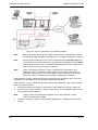
Figure 17: Typical Connections to a standard Presidium..................................................................... 22
Figure 18: PIR Alignment on Fenceline ............................................................................................... 24
Figure 19: Rear View of the Presidium ................................................................................................ 29
Figure 20: Cable Entry Requirements.................................................................................................. 30
Figure 21: Rear View of the Presidium Mini enclosure ........................................................................ 30
Figure 22: Typical Connections to a standard Presidium..................................................................... 31
Figure 23: Typical Connections to a Presidium Mini ............................................................................ 31
Figure 24: Connection to the VM15 Video Module .............................................................................. 33
Figure 25: PIR Connections (VM15 shown)......................................................................................... 35
Figure 26: Alarm and Isolate Input Configuration................................................................................. 36
Figure 27: Alarm Outputs ..................................................................................................................... 37
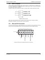
Figure 28: Pinouts for Presidium General I/O Connector..................................................................... 37
Figure 29: Pinouts for Presidium Mini I/O connector............................................................................ 38
Figure 30: Access/Secure Input Configuration..................................................................................... 39
Figure 31: Installation Screen .............................................................................................................. 43
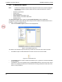
Figure 32: Presidium Setup Utility........................................................................................................ 44
Figure 33: Presidium Licence Agreement ............................................................................................ 44
Figure 34: Choose Setup Type ............................................................................................................ 45
Figure 35: Local Area Connection Properties ...................................................................................... 46
Figure 36: Internet Protocol Properties ................................................................................................ 46
Figure 37: Establish Connection to the Presidium ............................................................................... 47
Figure 38: Establish Connection to the Presidium ............................................................................... 48
Figure 39: Entering IP Address and Port Number................................................................................ 48
Figure 40: Port Redirection Example ................................................................................................... 49
Figure 41: Enter Password................................................................................................................... 50
Figure 42: Select Function ................................................................................................................... 51
Figure 43: Change Video Standard...................................................................................................... 51
Figure 44: Presidium Setup.................................................................................................................. 52
Figure 45: General Tab........................................................................................................................ 54
Figure 46: Contrast Level Indicator ...................................................................................................... 55
Figure 47: Camera Calibration............................................................................................................. 55
Figure 48: Areas................................................................................................................................... 56
Figure 49: Trigger Area Properties....................................................................................................... 58
Figure 50: Alarm Logic......................................................................................................................... 59
Figure 51: Detection Parameters ......................................................................................................... 60
Figure 52: Customise Detection Sensitivity.......................................................................................... 61
Figure 53: Alarm Behaviour ................................................................................................................. 63
Figure 54: Video Monitoring................................................................................................................. 65
Figure 55: Network Tab........................................................................................................................ 66
Doc. 12384_05
ADPRO Presidium by Xtralis
Installation and User Manual
Figure 56: IP Address Configuration .................................................................................................... 66
Figure 57: Advanced Communication .................................................................................................. 67
Figure 58: High Level Interface ............................................................................................................ 67
Figure 59: Security Tab ........................................................................................................................ 68
Figure 60: Status Tab........................................................................................................................... 69
Figure 61: Presidium Setup Screen ..................................................................................................... 70
Figure 62: Save to File ......................................................................................................................... 70
Figure 63: Load Settings from File ....................................................................................................... 71
Figure 64: Print Settings....................................................................................................................... 71
Figure 65: Software Upgrade option .................................................................................................... 72
Figure 66: Enter Password Window ..................................................................................................... 74
Figure 67: Reset Password.................................................................................................................. 74
Figure 68: Complete standard Presidium Installation........................................................................... 77
Figure 69: Typical Connections to a standard Presidium ..................................................................... 78
Figure 70: Installer Menu Icon.............................................................................................................. 79
Figure 71: Typical Video Transmitter User Settings............................................................................. 79
Figure 72: Presidium Inputs List........................................................................................................... 80
Figure 73: Unallocated Icon ................................................................................................................. 80
Figure 74: Presidium Input Settings ..................................................................................................... 81
Figure 75: Mapping the camera inputs. ................................................................................................ 82
Figure 76: FastTrace / FastTx / FastTrace-R Communications ........................................................... 82
Figure 77: Advanced Communication Properties................................................................................. 83
Figure 78: Typical Connections to a Third Party DVR.......................................................................... 85
Figure 79: VM15 Module Installation.................................................................................................... 87
List of Tables
Table 1: Quick Guide..............................................................................................................................4
Table 2: Video Output Display.............................................................................................................. 34
Table 3: Fault Relay ............................................................................................................................. 39
Table 4: Network Connection Indicators .............................................................................................. 41
Table 5: Video Motion Thresholds Explanation.................................................................................... 62
Table 6: Presidium Specifications ........................................................................................................ 89
Table 7: Horizontal FOV - 20 Metres (66 Feet) .................................................................................... 99
Table 8: Horizontal FOV - 22 Metres (75 Feet) .................................................................................... 99
Table 9: Horizontal FOV - 25 Metres (83 Feet) .................................................................................... 99
Table 10: Horizontal FOV - 30 Metres (98 Feet) ................................................................................ 100
Table 11: Camera Maintenance Table ............................................................................................... 105
Table 12: PIR Maintenance Table...................................................................................................... 105
Doc. 12384_05
Installation and User Manual
ADPRO Presidium by Xtralis
Doc. 12384_05
ADPRO Presidium by Xtralis
1
Installation and User Manual
Introduction
The Presidium Intelligent Video System is a high performance, modular, multi channel video
movement detection system. It is optimised for maximum protection and reliability in the outdoor
environment.
Presidium Mini is a high performance, DC powered, 2-channel video movement detection
system in a desktop/wallmount enclosure for the protection of smaller properties.
Note:
For consistency in this manual, the generic term “Presidium” is used to refer
to both standard Presidium and Presidium Mini.
Important: This symbol is shown next to the section where a feature or procedure
is not applicable to the Presidium Mini.
Presidium employs state of the art digital signal processing hardware and software to provide a
high level of performance by reducing unwanted alarms without compromising detection.
The Presidium has been designed to be fully compatible with all CCIR/PAL and RS170/NTSC
CCTV systems (monochrome and colour). It is simple to include in new designs or to retrofit to
existing CCTV systems to improve security.
1.1
•
•
•
•
•
•
•
•
•
•
•
•
•
1.2
•
•
•
Doc. 12384_05
Features of the Presidium
Modular expansion from 2 to 20 channels per Presidium chassis
Advanced algorithms to maximise target acquisition and tracking under a wide range of
environmental conditions
Low probability of false alarms from small animals, clouds, wind and rain
Multiple free form detection zones
Additional functionality to enhance the Presidium detection capability and reduce unwanted
alarms to near zero such as directional object detection, dual edge trigger areas used to
qualify alarms, single edge target detection and timer enabled detection for sterile zone
loitering.
Contrast alarms for sabotage detection
No video detection for camera, lens or cable failure
Easy to commission via quick setup feature
Single cable, High Level Interface to ADPRO FastTrace, ADPRO FastTx and ADPRO
FastTrace-R, reducing wiring and setup time, providing seamless integration (standard
Presidium only)
External access control input for easy integration into a security system
External detection inhibit input to reset all alarms
External alarm inputs for integration of other alarm sensors
Over temperature alarm (standard Presidium only).
Unique Features of Presidium Mini
Two channels
Small size footprint via desktop/wallmount enclosure
12V DC power supply supports battery based operation.
1
Installation and User Manual
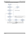
1.3
ADPRO Presidium by Xtralis
Installation Steps
The following steps must be followed to install a Presidium system:
•
•
•
2
Design the system
Gather site information (refer to Preliminary Information on page 7)
Discuss requirements with client
Survey the site (refer to Site Survey on page 7)
Select the equipment (refer to System Hardware on page 11)
Install the system
Commission the system
Install Presidium Setup Utility software on PC (refer to Install Setup Utility on page 43)
Configure the Presidium (refer to Configure Presidium on page 47)
Assess the system performance (refer to Performance Assessment on page 25)
Soak test the system (refer to Soak Tests on page 26)
Perform system tests (refer to System Tests on page 26)
Doc. 12384_05
ADPRO Presidium by Xtralis
2
Installation and User Manual
Design Guide
2.1
Introduction
The Presidium Intelligent Video System is designed to provide reliable and predictable detection
of intrusion into secure areas. The system analyses images from strategically placed CCTV
1
cameras to detect 'human-like ’ movement, and if the movement fulfils a number of criteria,
alarms are generated. These alarms can be handled locally or, coupled with ADPRO FastTrace,
ADPRO FastTx and ADPRO FastTrace-R and Monitoring Software, can be transmitted to a
remote central monitoring station, assessed and managed by experienced security personnel. A
well designed, installed and maintained Presidium system can remove the need for onsite
guards or patrols, or provide an adjunct to local monitoring, improving the effectiveness of the
overall site security.
2.1.1 Purpose
The purpose of this Design Guide is to describe the specification, design, installation,
commissioning and maintenance of Xtralis’s ADPRO Presidium Intelligent Video System. The
recommendations presented are designed to achieve optimal system performance and high
reliability. Although there are many variations to the recommended scenarios, any departure from
these recommendations may result in less than ideal system performance.
This document describes a typical installation scenario for a medium security Presidium system.
To provide a high security installation, where the intrusion is expected to be covert, detailed
consultation with Xtralis staff is required.
2.1.2 Scope
The following items are addressed in this Design Guide:
•
•
•
•
•
Presidium Operational Background
Site Survey and System Design
Equipment Installation
System Commissioning
Site and Equipment Maintenance
The following items are not discussed in detail in this guide:
•
•
•
•
Design, installation, configuration or maintenance of complementary detection technologies
excepting PIRs supplied by ADPRO (refer to other manufacturer's technical and application
information).
Installation or configuration of ADPRO FastTrace, ADPRO FastTx or ADPRO FastTrace-R
(refer to the FastTrace / FastTx / FastTrace-R Installation and User Manuals).
Installation or configuration of Xtralis’s ADPRO VideoCentral Monitoring Software (refer to
Central Monitoring Station Design Guide, Part No: 201700).
Any relevant Application Notes, Tech Tips and FAQs. Refer to Xtralis website www.xtralis.com.
1.Human-like: a feature that is able to differentiate between human and non-human movement for intrusion detection.
Doc. 12384_05
3
Installation and User Manual
ADPRO Presidium by Xtralis
2.1.3 Intended Audience
The intended audience for this Design Guide includes the following key stakeholders:
•
•
•
•
Security Consultants
System Integrators
System Installers
Facilities / Building / Site Managers
2.1.4 Other Resources
A number of other resources should also be used in conjunction with this Design Guide.
•
•
•
Presidium Design Forms - refer to System Design and Equipment Checklist on page 97.
Presidium Commissioning Forms - refer to Commissioning Checklist on page 101.
Presidium Maintenance Forms - refer to Site Maintenance Tables on page 105.
Where Remote Monitoring is a requirement, the Central Monitoring Station Design Guide should
be used in conjunction with this Design Guide.
2.2
Quick Guide
This guide divides the implementation of an Presidium system into four main areas:
•
•
•
•
System Design
System Installation
Site Commissioning
Site Maintenance
The Quick Guide shown in Table 1 provides an overview of key design considerations allocated
in each step and may be used as a quick reference. It should be used in conjunction with the
entire Presidium Manual to produce a robust system design.
Table 1: Quick Guide
4
Area
Key Design Considerations
Reference
Site Survey & Checklist
Conducting a site survey and what
information should be gathered
Site Survey on page 7 and Site Survey Checklist on
page 93
Illumination
Illumination selection and location for
use with Presidium
Illumination Requirements on page 19
Cameras
Camera selection and location for
use with Presidium
Camera Selection and Location on page 11,
Camera/PIR Alignment on page 19, Camera
Installation on page 22 and Camera / Lens Selection
on page 99
PIRs
Design and installation of PIRs with
Presidium
Other Detectors Selection and Location on page 15,
PIR Alignment on page 17, Camera/PIR Alignment
on page 19 and PIR Installation on page 23
Presidium Configuration
Configuring the Presidium system for
operation
Presidium Configuration on page 25
Commissioning and
System Test
Testing the system and checking the
detection performance
Performance Assessment on page 25, System Tests
on page 26 and Site Detection Tests on page 103
System Maintenance
Ensuring the system continually
operates to the required criteria
Site Maintenance on page 26, Site Detection Tests
on page 103 and Site Maintenance Tables on
page 105
Doc. 12384_05
ADPRO Presidium by Xtralis
2.3
Installation and User Manual
The Role of Security
Security is becoming an increasingly accepted part of every day living. It is imperative for
organisations to consider physical and information security as a fundamentally important element
of their overall management strategy. Suitable security must include detailed Risk Analysis and
Management as well as an awareness of Business Continuity Management, ensuring that the
system instituted provides the organisation with the best approach to achieve ongoing success.
The key elements to instituting a security solution are:
•
•
•
Identify and Evaluate Risks
Develop Strategy to Remove or Reduce Risks
Test and Monitor Strategy
2.3.1 ADPRO Solutions
ADPRO provides a range of video security solutions that focus on remote monitoring of facilities,
but also provide excellent onsite monitoring capabilities. The product range features video
transmission, video recording and video detection systems that link to an industry leading
software package, VideoCentral, for remote management and control. A typical approach to
security is to provide an indication when an intrusion has occurred, ADPRO, however,
recognises the value in being able to immediately identify the cause, evaluate the situation and
respond accordingly.
ADPRO's combination of onsite detectors, audio/video recording and transmission to monitoring
stations, provides security in a wide variety of markets and application areas. Presidium forms an
important element of security solutions where automatic detection and verification of an intrusion
is paramount.
2.3.2 Presidium - an ADPRO Solution
ADPRO Presidium and Presidium Mini, in conjunction with the other Xtralis products, are ideally
suited for security solutions where the risk is illegal intrusion into a high value asset. The
Presidium approach provides reliable protection of a perimeter or sterile area, with rapid
identification of the cause of any intrusion within that perimeter.
The Presidium system, coupled with other ADPRO technologies, can form an important link in
responding to different scenarios:
•
•
Doc. 12384_05
A remotely monitored standard Presidium System, linked to a FastTrace or FastTx provides
rapid remote response, with an option for local response follow up. The response from a
remote monitoring station, followed by dispatch of security guards or law enforcement
provides a powerful, flexible and effective solution to many site security problems.
The presence of a Presidium System at a site can provide rapid local response. When local
notification via standard CCTV monitors is linked to alarm systems for visual and audible
notification at a local monitoring station, it is possible for guards to respond appropriately in
the minimum timeframe. Automatic monitoring of multiple video channels provides
significant security and cost benefits.
5
Installation and User Manual
2.4
ADPRO Presidium by Xtralis
Presidium System Concept
This section provides a brief description of how Presidium performs image processing to
determine if an intruder is present in the protected area.
2.4.1 Operational Concept
Presidium analyses video from CCTV cameras to detect movement that is likely to be an
intruder. A number of criteria, used in conjunction with complex image processing routines, are
used to distinguish between an intruder and some other form of movement. The same
techniques are used to reduce other factors such as changes in contrast from shadows cast by
clouds and moving trees.
Presidium monitors contrast changes and rate of contrast change within the defined detection
areas. This information on contrast changes and rates of change is fed into a number of
computational routines that analyse the changes and extract valid targets from the images whilst
rejecting changes from background movement. The detected targets are further analysed to
ensure that they meet criteria based on size and speed. If the criteria is met, an alarm is
generated.
What is actually considered a target will depend on your particular security requirements. In a
high security environment, the maximum horizontal Field of View (FOV) should be less than for
that in a medium security environment.
2.4.2 Basic Parameters
To achieve high detection probability and effective nuisance alarm rejection, the field of view at
the maximum detection distance should be no more than 16.7 times the target size.
For example, to detect a 1.8m high human target, the recommended maximum field of view at
the maximum detection distance is:
FOV = 16.7 x 1.8m = 30m
If a larger field of view is used, then the detection probability is reduced.
In this scenario, increasing Presidium's sensitivity can only partially compensate for the reduced
detection probability and may lead to an increase in the number of false alarms. It is not
recommended.
The maximum horizontal FOV, and the required target size to be detected determines the
required camera and lens configuration.
2.5
System Design
The system design phase consists of three elements:
•
•
•
6
Preliminary Information: Gather general site information and discuss the security
requirements with the customer to ensure that the Presidium meets the customer's
requirements.
Site Survey: Conduct a site survey to determine site requirements such as the positioning
of cameras and other detectors, lighting, and existing and required communications
infrastructure.
Equipment Selection: Conduct a comprehensive analysis to determine equipment
requirements, such as camera types and lenses, level and type of illumination, and
communications and control room equipment.
Doc. 12384_05
ADPRO Presidium by Xtralis
Installation and User Manual
The system design is critical to ensure that the Presidium system performs as expected. A welldesigned system can deliver exceptional performance, whereas a system that has not had a
rigorous design process will not perform to expectations. Presidium provides a high level of
flexibility in its configuration, but is dependent on the quality of video signals and scene content
to deliver a high performance solution.
2.5.1 Preliminary Information
Gather site information to determine Presidium's suitability for the site. If possible, obtain a copy
of the site plans to check the layout and suitability of Presidium.
Assess Site Plans
Assessing the site plans prior to visiting the site allows a quick overview, as knowledge of this is
important for a good Presidium system design. If unable to obtain site plans prior to visiting the
site, then once on site prepare a sketch of the site, remembering to include the immediate
external environment, such as roads and location of neighbouring buildings.
Discuss Requirements
During the preliminary stages, discuss the security requirements and expectations with the
customer's representative. Different areas of the site may have varying security requirements
and knowledge of the external environment is critical in understanding the customer's
requirements and performance expectations from the system. Collect information about the
customer's response requirements, such as use of local guards and/or remote monitoring.
Recommendations
If, after the preliminary investigation phase, the site is deemed suitable for Presidium and the
customer's performance expectations can be met, a site survey should be conducted. The
following criteria determine the site's suitability for a Presidium System:
1.
2.
3.
4.
5.
Sterility of protected area, i.e. how well defined is the border surrounding the protected
area, is the area free from general or expected activity, and are there clear areas in which
detection can occur.
Customer requirements for response (onsite or remote).
Customer expectations of system performance, such as false alarms or integration into third
party systems.
Possible addition of other detection technology, e.g. PIR.
At the maximum distance from the camera where a target is expected to be detected, the
horizontal field of view should not exceed 25m, or 20m for high security.
2.5.2 Site Survey
Once preliminary information is collected and the site considered suitable for protection with
Presidium, a site survey can be conducted. Conduct the site survey taking into account any
customer tender or requirements documents to ensure that the survey and subsequent design
meet the customer's specifications and requirements. The site survey draws on the preliminary
information to design a complete system. Determine all necessary criteria for the system and
ensure all relevant information is collected. Where clarification is required, ensure that this is
received from the customer (or their representative). Appendix B contains a checklist for a Site
Survey.
The items required to perform a detailed site survey include (1) Digital Camera (2) Tape measure
(3) Workbook, and (4) Site Plans (accurate engineering drawings of the site).
The different stages of a site survey are described below.
Doc. 12384_05
7
Installation and User Manual
ADPRO Presidium by Xtralis
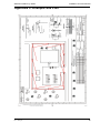
Detailed Site Plan
The production of a detailed site plan annotated with key information (refer to Appendix C for an
example) is the key element in completing a successful site survey. As a minimum, the following
information must be included:
1.
Location and type of existing illumination, including coverage, to determine its suitability. If
necessary specify additional illumination.
2. The location for the installation of the Presidium system, to confirm cable run lengths for
cameras.
3. If remote monitoring is to be used, confirm the location and type of any existing
communications infrastructure.
4. Location of trees, and other vegetation that may affect detection performance, camera
positioning and field of view.
5. Type and height of fences or barriers to check where intrusion is likely to occur. Also
determine if any concealment of intruders may occur, and what is visible through fences.
6. Any other permanent or semi-permanent structures not already marked on the site plan,
e.g. semi-permanent location of large cable drums, which may obscure camera views.
7. Location of any nearby roads, to determine whether street lighting or car lights from any
roads nearby may present a lighting problem.
8. Location and description of nearby buildings or structures to understand whether lighting
may spill from adjacent properties, or shadows from industrial equipment may affect
performance, e.g. a shadow from a moving crane cast across the FOV of a camera may
cause nuisance alarms.
9. Location of any existing CCTV cameras or other detectors and their suitability with the
Presidium system, or incorporation as a third party detector.
10. Special requirements within protected areas, i.e. high security critical areas within the site,
or special requirements due to dangerous chemicals and/or service reliability.
11. If audio is considered for offsite response, identify the location of any noisy equipment, e.g.
generators, to ensure that any microphones to be installed will not be affected by the noise.
This also relates to onsite audio broadcast equipment, i.e. speakers and horns should be
appropriately located and specified with appropriate power.
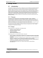
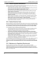
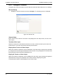
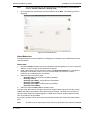
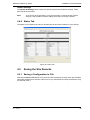
Site Images
Collect a detailed set of site images covering all protected areas. The site images provide a
visual reminder when assessing the site plan offsite. These also provide a reference point during
installation and commissioning. Ideally the digital images should be taken under a variety of
lighting conditions, i.e. dawn, daylight, dusk and night. The most challenging lighting conditions
for CCTV systems can occur at dawn and/or dusk. It is vitally important to be aware of the
variable lighting conditions under different circumstances and in different seasons.
The detailed site survey must consider the likely occurrence of seasonal variations. Shedding or
sprouting of new leaves on nearby trees may affect lighting conditions and camera views. Ideally
there should be no trees in any camera views, however this is not always possible. Lighting and
views change as foliage grows or drops, affecting nuisance alarm rates or detection probability.
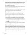
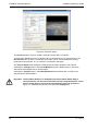
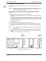
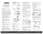
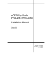
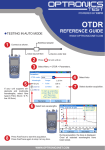
The following images illustrate some suitable and unsuitable perimeter and area protection
scenarios for a Presidium system.
8
Doc. 12384_05
ADPRO Presidium by Xtralis
Installation and User Manual
Figure 1: Suitable/Unsuitable Perimeter Conditions
Doc. 12384_05
9
Installation and User Manual
ADPRO Presidium by Xtralis
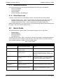
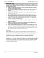
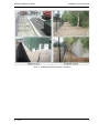
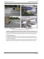
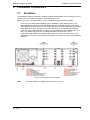
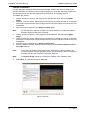
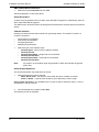
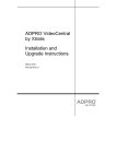
Figure 2: Suitable/Unsuitable Area Detection Scenes
Presidium is used in perimeter and area protection scenarios. The key to providing a successful
solution is installing Presidium into a scenario that is suited to its requirements. Essentially, the
sterility of the area/perimeter to be protected is paramount. It is essential to have clear areas for
target observation with minimum continuous or sporadic movement from non-target sources.
Clarify Requirements
The exact requirements for site security must also be clarified through tender documents or
engineering specifications. This is vital to ensure that the system design and installation meets
the customer's expectations.
It is good practice to draft a commissioning schedule to further clarify the system acceptance
criteria. Details of system commissioning are described in Site Commissioning on page 25.
10
Doc. 12384_05
ADPRO Presidium by Xtralis
Installation and User Manual
2.5.3 System Hardware
Appendix D contains a checklist for system design and equipment selection.
Camera Selection and Location
The selection and location of cameras is vitally important for the successful operation of the
Presidium Video Intrusion System. The cameras are intrinsically linked with any other detectors
in use and the availability of suitable lighting.
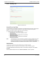
1. Camera and Video Signal Requirements
Cameras must adhere to the CCIR/PAL or RS170/NTSC standard for suitable operation with
Presidium. Each camera channel can pass both colour and monochrome video signals.
Presidium only processes the monochrome section of the video signal. Any colour signal
present, neither adds nor detracts from the performance.
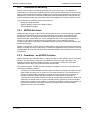
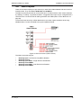
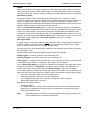
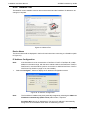
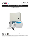
The following conditions must be met for the Presidium to synchronise to an incoming video
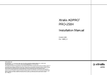
signal from the camera and to provide good video motion detection:
•
•
The sync amplitude at the video input of the Presidium must be within 0.2V to 0.4V range
The video amplitude (not including sync) at the video input of the Presidium must be within
the range of 0.5V to 1.0V.
Figure 3: Required Video Signal
If the video level at the video input of the Presidium is low, cable compensators, or line drivers,
should be installed at the camera end and adjusted to boost the video signal to within the correct
voltage levels. Typically, the best solution is to ensure that the correct grade of coaxial cable is
installed to transmit the images over the required distance. Take into consideration impedance
and capacitance qualities of the selected cable type to ensure that image degradation is
minimised from the outset.
The quality of the video is influenced by the cable length. Generally the shorter the cable runs
between the Presidium and the camera, better the quality of the picture. For long cable runs,
cable compensators may be required.
A video contrast level indicator may be displayed on the Presidium video output, if required, to
assist with setting the video contrast levels. Refer to Display All Tracks on Video Output on
page 54 for more information.
Doc. 12384_05
11
Installation and User Manual
ADPRO Presidium by Xtralis
2. Camera Field of View (FOV)
Setting the correct horizontal FOV of the camera is critical for reliable detection. The horizontal
FOV determines the lens required on the camera. The following guidelines are important:
•
•
•
•
•
•
Ensure there is adequate detection area. The minimum detection area requirement is 6m
(19ft) width, i.e. if there is only a 2m (6ft) gap between a building and a fence, then reliable
detection will not be possible.
Ensure that the horizontal FOV at the maximum detection range does not exceed the
recommended maximum of 25m (82ft).
The tilt of the camera should be such that the FOV does not include large areas of the sky,
thereby reducing the detection area of the Presidium system.
Ensure the FOV is clear, with minimum views of foliage and obstructions that provide cover
for intruders.
Presidium uses perspective compensation for its motion detection algorithms, hence it is
important that the FOV is not obtuse, i.e. a target in the background on the left edge of the
FOV must be the same size as a target on the right edge of the FOV.
When designing cameras to look along a fenceline, the majority of the horizontal FOV of the
camera should be on the monitored side of the fence.
3. Camera and Lens Selection
The maximum horizontal field of view and the likely target size to be detected, determines the
required camera and lens configuration. The absolute maximum horizontal field of view where
detection occurs should not be more than 30m (98ft).
Presidium functions most effectively when the camera is not mounted too high. The perspective
characteristics used in the detection algorithms will not function as expected when the camera is
mounted too high. When looking directly down on a cat or a person, their relative sizes are quite
similar, the true sizes can be judged only when viewing at an angle. Place the camera at a height
that it is out of reach of intruders. This should be between 3 - 6 metres (9.8 - 19.7ft). The ideal
height is 4.2m (14ft), as this allows the detection algorithms to function and is high enough to
prevent tampering with the camera.
Analysis of the site plans and information from the site survey determine the FOV of the camera
to ensure coverage of all areas requiring protection. Always ensure that the maximum horizontal
FOV is no greater than 25m (82ft), to avoid compromising detection of small targets.
The tables in Appendix E show the approximate maximum distance between the camera and the
target for reliable detection, at a maximum horizontal field of view of 20m (66ft), 22m (75ft) and
25m (82ft) respectively. The approximate dead zone beneath the camera is also shown, for a
camera mounted at 4.2m (14ft), although this will vary depending upon the final angle at which
the camera is set. These figures should be used for guidance only. Other considerations, such as
lighting and external environmental aspects, may dictate the use of different camera/lens
combinations.
The formula for determining the distance from camera to target based upon the maximum
horizontal FOV is as follows:
(Lens focal length) x (Maximum horizontal field of view)
Distance between camera and target = ____________________________________________
(Camera format width)
Where:
12
Distance between the camera and target is in metres.
Maximum horizontal field of view is in metres
Lens focal length is in millimetres
Camera format in millimetres =
8.8 mm for a 2/3" camera.
6.4 mm for a 1/2" camera.
4.4 mm for a 1/3" camera.
3.2 mm for a 1/4" camera.
Doc. 12384_05
ADPRO Presidium by Xtralis
Installation and User Manual
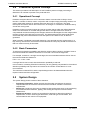
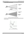
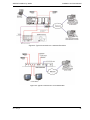
4. Dead Zones
The dead 'zone' is the area under the camera that the camera cannot view and should be
considered during system design. The following figure shows the dead zone area.
Figure 4: Camera Dead Zone
Camera positioning should be such that the 'dead zone' of one camera is covered by another
camera's field of view. The area just in front of the 'dead zone' can also be vulnerable to fast
moving targets. It is a good practice to ensure that the field of view of the camera covering the
'dead zone' includes the 'dead zone' plus an extra 10% to 15% of the area adjacent to the 'dead
zone'. The following diagram shows the camera's FOV and 'dead zone' in both perimeter and
area protection scenarios.
Figure 5: Camera Dead Zone Coverage
5. Optimal Camera Angle
Figure 4, which shows the 'dead zone' of a single camera, also shows the optimal camera angle.
The target closest to the camera should have its feet at the base of the camera FOV, and the
head of the target at the furthest detection distance should be just below the top of the FOV of
the camera.
Normal video monitors do not show the full horizontal video available. Presidium uses all of the
horizontal video for detection. Hence when aligning cameras, it is important to take this into
account, and if normal monitors are to be used (as opposed to underscanning monitors), then
care must be taken to mask out the extreme left and right hand edges of the image using the
detection area selection capability of Presidium.
Doc. 12384_05
13
Installation and User Manual
ADPRO Presidium by Xtralis
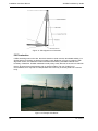
6. Camera Positioning and Mounting
The position and mounting of cameras is vital to ensure reliable performance from a Presidium
System. The essentials when choosing a position and mount for cameras are:
•
Ensure the camera mount and pole are stable, even in windy conditions. As the lens size
increases, smaller movements appear magnified and the stability of the camera mounting
becomes increasingly important. Ensure that there are at least three mounting points on the
selected camera housing mounting. A camera mounting used for a standard CCTV site
implementation may not be suitable, as some camera movement generally does not cause
distress to an operator, however Presidium relies on steady camera images. Though the
algorithms within Presidium allow for some camera shake, it is advisable to use a heavy
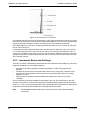
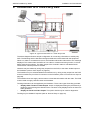
duty mounting location or pole. The following figure shows a typically recommended
mounting pole for a camera/PIR combination as well as infra-red illuminator.
Figure 6: Recommended Presidium Pole Installation
•
•
14
The position of the cameras relative to lighting is extremely important. Do not install
cameras close to lights (particularly infrared illuminators) which could attract insects, or face
cameras into lights, windows, the sun, or in areas which have a large number of reflections
or shadows. When the lighting is below or to the side of the camera, the recommended safe
distance is 2 metres (6 feet).
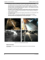
If the lighting is directly above the camera, then insects flying up towards the light in front of
the camera may cause nuisance alarms or obscure the view. If this is the case, ensure that
the lighting is well above the camera, in excess of 4m. The previous image of the pole
shows the location of an IR illuminator. The figure below shows this in greater detail.
Doc. 12384_05
ADPRO Presidium by Xtralis
Installation and User Manual
Figure 7: Presidium Pole Front View
•
•
•
•
Do not install cameras facing at trees or plants, which may move in the wind or drop leaves
(tree shadows may also move in the wind). In many circumstances this is unavoidable, but
should be limited as far as possible. Use the Presidium detection area selection
functionality to mask out areas with foliage.
Do not install cameras facing into areas where there is likelihood of vehicle headlights at
night. The presence of roads near sites is unavoidable, and the positioning of cameras must
account for this. The placement of opaque material on fences near roads can alleviate most
nuisance alarms from lighting.
Take into consideration the position of sunrise and sunset, as well as reflections from
objects in the FOV to limit any 'blinding' of the camera due to bright light.
Do not install cameras facing into bright lights or IR illuminators.
7. Cable Selection
Typically RG59 standard (75 ohm) cable should be used as a minimum requirement:
•
•
In a monochrome system, the cable length should be restricted to 250m (800ft) before
cable compensators are installed.
Signal degradation due to cable length has a far greater effect on colour video, where the
coaxial cable should be restricted to 150m (500ft) before cable compensators are installed.
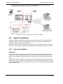
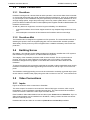
Other Detectors Selection and Location
The rationale behind using an additional detection technology is to provide a system that is not
susceptible to any one possible cause for nuisance or false alarms, i.e. using complementary
technologies to limit false and nuisance alarms whilst maintaining the highest detection
probability. ADPRO recommends using either long-range (for perimeter protection) or wide-angle
(for area protection) Passive Infra-Red (PIR) technology in conjunction with Presidium.
In many instances using other detection technologies with Presidium is extremely beneficial to
provide a 'double-knock' scenario. 'Double-knock' installations using a different technology can
reduce nuisance and false alarm rates to minimal levels, dramatically increasing the overall
effectiveness of the system. The benefit of verifying the nature of the intrusion through video
images is paramount, with the additional technology providing an extra level of security.
The use of PIR detectors is a well-established and field-hardened method of providing security.
The ADPRO range of PIR detectors feature long range and wide angle detectors suitable for
perimeter protection and for area protection respectively. The operable range of the detectors
varies from 18m (60ft) for the wide angle, up to 150m (500ft) for the longest range PIR. Prevailing
site conditions determine the effective range. The recommended maximum is 100m (330ft).
Doc. 12384_05
15
Installation and User Manual
ADPRO Presidium by Xtralis
The following diagrams illustrate the alignment of a long range PIR with the camera field of view,
and a wide angle PIR with the camera FOV.
Figure 8: FOV of Curtain PIR with Camera
Figure 9: FOV of Wide angle PIR with Camera
To aid aligning the camera and the PIR it is recommended that the PIR is mounted as close to
the camera as possible, preferably mounting off the same bracket as the camera, as shown in
the following diagram:
Figure 10: Camera/PIR Mounting Details
16
Doc. 12384_05
ADPRO Presidium by Xtralis
Installation and User Manual
The difference in dead zones of the two technologies is an important factor to consider when the
PIR/camera combination is used. The PIR may have a very steep downwards angle, whereas a
camera may have a much larger dead zone, as illustrated below. This is a very important
consideration as a moving target in the camera's dead zone may activate the PIR. The target will
not be visible to the camera mounted with the PIR, however the target will be visible to the
camera covering the first camera's dead zone. If the PIR/camera dead zones require matching,
carefully check the comparative dead zones to ensure that this can be achieved.
Also consider mounting the PIR and camera on separate poles.
Figure 11: Camera/PIR Dead Zone Comparison
The installation and use of any detection technology should consider:
•
•
•
•
•
•
The angle of elevation and the horizontal alignment with the camera is critical in providing a
high degree of performance.
It is recommended to keep foliage trimmed and grass cut for a clear PIR and camera FOV.
Termination barriers are important so that targets past the protected area are not detected.
Minimise reflective material in the FOV to ensure reflections from sunlight do not affect the
PIR.
Minimise facing PIRs in the direction of sunrise or sunset.
PIRs also require a maintenance program to clean the lenses and to regularly check
performance and alignment.
PIR Alignment
For good PIR performance ensure PIR and camera alignment match. The following figure shows
the optimal PIR placement angle, where the top of the curtain is approximately 1m (3ft) high at
the maximum detection range.
Figure 12: Optimal PIR Angle
When using a long range PIR next to a fenceline, it is important that the PIR curtain is aligned
approx 0.5m (2 ft) inside the fenceline, as shown in the next figure.
Doc. 12384_05
17
Installation and User Manual
ADPRO Presidium by Xtralis
Figure 13: PIR Alignment on Fenceline
PIR Termination
If PIRs are being used on the site, then their detection curtain must be terminated suitably, in a
similar fashion to blocking out lights from nearby roads. Referring to Figure 15 under the PIR
alignment section, the detection curtain should be terminated by a suitable material at the
boundary of detection. Suitable materials include privacy mesh that can be woven into chain link
fences, plywood, heavy landscaping cloth or plastic facades. The use of steel is not
recommended, as it may heat to a temperature that a PIR may incorrectly detect as a human
body.
Figure 14: Example PIR Barrier
18
Doc. 12384_05
ADPRO Presidium by Xtralis
Installation and User Manual
Camera/PIR Alignment
The camera alignment relative to the boundary and other cameras is paramount in ensuring that
there are no 'blind-spots' on the site. Align each camera to cover the dead zone of the next
camera, and to adequately cover the area under protection. If, due to practical limitations,
external areas not requiring detection are included in the camera view, use the detection area
selection feature in Presidium configuration to mask out such areas. The following figure shows
camera alignment and PIR alignment around the perimeter of a facility.
Figure 15: Camera/PIR Alignment
Illumination Requirements
Ideally, the illumination around the site should be even, with no major contrast changes caused
by shadows at all times of the day and night. Typically, to provide more even illumination, it is
better to utilise high levels of ambient lighting throughout the field of view of the camera rather
than subjective lighting systems. To ensure continuous monitoring by Presidium, the lighting (or
illuminators) should be on at all times during hours of darkness (typically photo-cell controlled).
Switching illuminators on at the point of alarm in order to deter intruders is not effective because
if illumination levels are too low, Presidium may not detect the intrusion. If the scene contrast is
poor, and no additional lighting can be installed, then the contrast can be increased by adding
stripes to walls and pathways, by painting the background surfaces a light colour or by laying
strips of different colours of gravel.
Determining the required lux level from a mathematical calculation can be difficult. There are
references available that describe this process in detail. Refer to these references, or other
sources for a mathematical approach in determining the lux level required at a site to provide
adequate illumination for the cameras selected. Lux meters are available for checking the
illumination level at a site and to relate the measurements to camera specifications. A good rule
of thumb is, if the target is clearly visible to the human eye at the maximum range under the worst
lighting conditions, then a camera can detect it.
Doc. 12384_05
19
Installation and User Manual
ADPRO Presidium by Xtralis
The following are some key considerations in determining the best illumination method:
•
•
•
•
•
The requirements will dictate if IR illuminators or visible lighting is used. The cameras used
with IR illuminators must be either B&W or day/night cameras capable of automatically
switching between colour/B&W depending on the conditions. Visible lighting must be used
for colour cameras. The level of lighting required is higher for colour cameras as these have
less sensitivity compared to B&W cameras.
The sensitivity of the cameras determines the required level of illumination. When visible
illumination is used, the lighting should be sufficient for the human eye to see targets at the
maximum detection range. When using IR illumination, verify the intensity by viewing the
camera output on a monitor.
It is important to ensure that areas where lighting casts shadows do not provide dark areas
for intruders to utilise.
Illuminators (visible or IR) should not be positioned to face directly into a camera.
Typically, the best type of visible lighting is closest to normal daylight, i.e. a white light
source rather than a coloured light source such as sodium vapour.
Figure 16: Correctly Illuminated Scenes
Equipment Room
The equipment room for mounting the Presidium equipment should meet the following
requirements:
20
Doc. 12384_05
ADPRO Presidium by Xtralis
Installation and User Manual
Environmental Requirements
The equipment room should meet the following environmental specification:
•
•
•
Temperature: 0°C (32°F) to 40°C (104°F) - standard Presidium
Temperature: 0°C (32°F) to 40°C (104°F) - Presidium Mini
Humidity: less than 90% non-condensing
Power Supply
Depending upon security requirements, a backup power supply (such as a UPS) should be
considered. To ensure total system reliability in the event of power failure, a backup supply would
also need to provide power for all the cameras and other detectors, as well as any
communications equipment. Refer to Power Connection on page 32 for details on power
consumption, and the manuals for respective equipment for their power consumption details.
Access Requirements
Access to Presidium equipment should be limited to authorised personnel. An access control
system may be used to limit access.
Equipment Mounting
Presidium is compatible with 19" racking systems. To ensure proper cooling, ideally allow
spacing equivalent to 1U between different equipment in the racking. Consider providing cooling
within the rack if the rack has a significant amount of equipment.
Presidium Mini is housed in a desktop/wall mount enclosure. To ensure proper cooling, the
enclosure must be location where it is clear of other heat generating equipment (for example,
computers, printers. photocopiers, generators etc). Do not place the enclosure in a position
where it will be subject to strong or continuous sunlight.
Monitoring Equipment
A standard Presidium system may be remotely monitored through a FastTrace / FastTx/
FastTrace-R and VideoCentral.
Refer to the Central Monitoring Station Design Guide for details of selection, configuration,
operation and maintenance of the remote monitoring station equipment.
Communications Infrastructure
For remote monitoring to be used with ADPRO products, suitable communications infrastructure
must be provided. There is a range of communications media choices available for use, such as
PSTN, ISDN, ADSL, microwave or RF. The type of communications link is dependent upon a
number of criteria:
1.
2.
3.
4.
5.
Doc. 12384_05
Existing infrastructure: To provide a cost effective solution, consider using any existing
communications infrastructure at the site, subject to it meeting required bandwidth and
other operational requirements.
Backup communications: Under some circumstance, a secondary communications link
may be required if the primary method is negated.
Availability: Consider the availability of different telecommunications options, as not all
telecommunication solutions will be provided by a single provider, or site requirements
might exclude certain types of communications.
Installation and operational cost: The installation and operational cost are a major factor
in deciding the type of communications infrastructure selected. The cost is generally linked
to the bandwidth provided on the link.
Bandwidth requirements: The expectation of bandwidth, which ultimately drives how
quickly video information can be transmitted, is extremely important to ascertain. Links with
throughput of 9600 baud right through to 2 mega baud are available. ADPRO video
21
Installation and User Manual
ADPRO Presidium by Xtralis
transmitters are optimised for operation over low-bandwidth links, however they also
provide outstanding operation over higher bandwidth links.
Figure 17: Typical Connections to a standard Presidium
2.6
System Installation
Install the Presidium system and associated hardware in accordance with appropriate CCTV
installation practices. Ensure adherence to any local, legal or mandatory requirements for
electrical or telecommunications infrastructure.
Appendix I contains a flowchart providing an overall view of the installation and commissioning
process. It can be used as a guide for the installation and commissioning sequence of events.
2.6.1 Camera Installation
Alignment
Confirming the FOV of the camera is very important. The initial design must ensure that the
perimeter (or area) is completely protected and no dead zones are present. Adherence to the
design during installation ensures there will be no dead zones or blind spots in the protected
area.
Placing traffic cones or markers at the edges of the expected detection areas (foreground and
background) provides a mechanism to initially align the camera and ensure that the FOV is as
per requirement. Alternatively have one person watch a monitor and direct another (use a walkietalkie) to walk the site.
22
Doc. 12384_05
ADPRO Presidium by Xtralis
Installation and User Manual
Installation Hints
When installing cameras in camera housings, the following hints will avert some nuisance
alarms.
•
•
•
The application of insect repellent material such as pest control strips or surface spray
reduces any nuisance alarms caused by insects or spiders in or near camera housings.
Place a bead of silicone across the top of the shield or housing near the front. This prevents
water droplets falling in front of the camera off the front of the sun or rain shield of the
housing. When water hits the bead, it diverts to the side and does not collect along the front
of the housing.
Rain or sun shields can catch the wind, causing significant camera shake. To restrict
camera movement, appropriately increase the strength of the fixing hardware as the size of
the shield increases.
Interference Caused by High Voltage or Ground Loops
There is significant potential for interference to video signals in some installations, particularly on
sites with high voltage infrastructure, such as electricity substations. High 'ground loop' currents
are produced between equipment earthed at different points around the site. Depending upon
the level and type of interference, the ground loop currents have the potential of causing
nuisance alarms or a reduced detection rate by causing interference on the video signal (i.e. the
picture displayed on the monitor). During the design stage it is important to consider the
likelihood of interference from high voltage or ground loops, and factor counter measures into the
design, such as floating earths, and isolation transformers on video signals.
Installation Adjacent to Roads
Headlights sweeping across the area under surveillance have the potential to cause nuisance
alarms. If the area is near a road and has the likelihood of headlights sweeping over it, consider
some sort of light barrier to ensure the headlights do not cause nuisance alarms. The options for
light barriers includes a solid panel such as plastic or metal facades placed on fences next to the
road, high opacity shade or greenhouse/landscaping cloth, or privacy mesh interwoven on chainlink fences.
2.6.2 PIR Installation
Alignment
Aligning the PIR with the camera is critical for good performance. There are a number of ways of
checking PIR alignment.
•
•
•
•
Doc. 12384_05
A slot in the top of some of ADPRO's range of PIRs can be used as a simple method to
align the PIR. Looking through a drinking straw into the slot, or resting a laser pointer in the
slot can be used to help with alignment.
ADPRO offers an alignment telescope for aligning PIRs across the full range.
A cordless walk tester (CT 45) is available. During a walk test it indicates a detector alarm
with a beeper and an LED.
In addition, a tester and software available for each type of ADPRO PIR provides a very
accurate method of aligning the PRO detector. The tester provides an output showing the
IR activity that the PIR is sensing. This requires two people, where one acts as a target
while the other adjusts the alignment of the PIR to cover the required detection area.
23
Installation and User Manual
ADPRO Presidium by Xtralis
Figure 18: PIR Alignment on Fenceline
It is important that the PIR curtain is aligned approx 0.5m (2ft) inside the fence when a long range
PIR is used next to a fence line (the previous figure illustrates this). The PIR can be aligned using
previously described methods. Confirm correct alignment, with a walk test performed
immediately adjacent to the fence, ensuring that detection does not occur in the 0.5m (2ft) area
directly next to the fence.
It is important to ensure that the extents of the PIR detection are within the FOV of the camera,
i.e. if a wide angle type PIR is used, the camera FOV must overlap the PIR detection area. To
confirm this, the alarm output status (or the test output using the PIR tester software) of the PIR
should be monitored as a person walk tests the site. Ensure the person remains within the FOV
of the relevant camera.
2.6.3 Instrument Racks and Cablings
There are a number of standard procedures that should be followed while installing any electrical
equipment including a rack mounted Presidium:
•
•
•
•
Ensure all local safety regulations regarding installation of electrical equipment are
followed.
All cables should be routed neatly and held in place using routing trays, channels or ties.
All cables should be labelled for future reference and the identifiers marked on cabling
diagrams or plans.
Adequate space should be allocated between all equipment in the rack to provide
ventilation.
Once all equipment has been installed and operating in the rack, the temperature in the rack
should be monitored to check that the equipment is operating within specified limits (operating
range 0°C - 40°C). Even though equipment may be operating within specified limits, reducing the
temperature will increase the operable life of all equipment in the system.
Note:
24
Do not stack Presidium Mini units on each other due to heat transfer between
enclosures.
Doc. 12384_05
ADPRO Presidium by Xtralis
2.7
Installation and User Manual
Site Commissioning
The Commissioning Phase consists of the following steps:
•
•
•
•
Presidium Configuration
Detection Tests
Soak Tests
Monitoring Tests
Appendix F contains a commissioning checklist for each Presidium channel.
2.7.1 Presidium Configuration
The first element of Site Commissioning is to configure the Presidium system. Refer to
Installation / Configuration on page 43 for instructions.
2.7.2 Performance Assessment
Detection Tests
Presidium, as a detection system, should initially be configured to ensure detection occurs
effectively, and then corrective action can occur to limit any nuisance alarms. Whilst performing
the detection tests, it is important to ensure that the tests are adequately documented and
described for proper ongoing maintenance. A subset of the tests should be performed on a
regular basis to confirm correct operation. The detection tests should also be annotated on a site
plan to highlight the areas where the tests are performed. Refer to Site Maintenance on page 26
for a description of the necessary maintenance procedures.
Site Detection Tests on page 103 contains a table for documenting the detection tests performed
and their outcome. Prior to performing the detection tests, Display all Tracks on Video Output
should be disabled. Refer to General Setup on page 54.
For each detection area, the following should be performed:
•
•
•
Doc. 12384_05
Check that the detection area covered by each camera connected to Presidium matches
the design, and that the detection areas programmed for Presidium are correctly aligned
within the field of view of the camera.
Check that any PIR detector is aligned as initially designed. This may require using the PIR
tester and software to ensure that the angle of the tilt is correct, i.e. approximately 1m (3ft)
high at the maximum detection distance, as well as the horizontal alignment of the PIR,
using another person as an IR target when required.
Determine the level of intrusion to be detected, such as a casual opportunistic intruder, or a
well planned and executed covert intrusion. Design and document tests based around the
security level and scene content. Factors that may vary include the speed of target, the size
of the target and the location in the scene. The following describes how to perform the tests,
and is suitable for both the PIR and Presidium detection testing:
Tests should be performed at three separate locations: the foreground FOV, in the
middle of the scene and at the maximum FOV.
The target should move to the point where intrusion would expect to start. If this is
within the detection area, then once the target has moved to the start point, the target
should stay motionless for one minute to allow Presidium to settle.
The target should then perform the detection test. As a minimum a walk test and a run
test should be performed at each distance. More tests can be performed as required in
each individual scene, but most importantly all possible intrusion points must be tested.
For size discrimination testing, a small target, such as a basketball rolled across the
scene, could be used to check that small targets are or are not being detected by
Presidium as required.
25
Installation and User Manual
•
•
ADPRO Presidium by Xtralis
Execute tests in each detection area based on the type of intrusion, and where possible
differing environmental conditions, e.g. day/night/dusk/dawn. Ensure that the alarm
activation is reported as expected at the Presidium system, and also that any third party
system triggered from the Presidium system receives an alarm notification.
If the system is installed in a high security installation, then tests with different types of
camouflaged clothing should also be performed.
Soak Tests
Once the system has been installed and the detection tests performed, then the system must be
monitored for its performance in relation to the ambient environment. Changes in environmental
conditions, or just routine actions can produce nuisance alarms. The system should be
monitored on a daily basis prior to going 'live' to highlight issues of concern, and then adjust the
Presidium parameters as required. Every time detection parameters are modified, detection tests
should be performed again to ensure the detection performance has not been compromised.
Once the performance of the soak tests has reached an acceptable level, and the detection
performance is as required, the system can go 'live'.
2.7.3 System Tests
Typically Presidium is an element of a larger system. The integration and performance of
Presidium as a system component must be verified to ensure the complete system behaves as
required and expected. There are a number of areas to check:
•
•
•
For remote monitoring, ensure that generated alarms are successfully transmitted to the
Central Monitoring Station.
If functions such as Access/Secure are being used within Presidium, test that the behaviour
meets expectation and the system generates alarms when it is armed.
If the Presidium is integrated into a larger matrix or CCTV system, ensure that any inputs/
outputs to/from the larger CCTV system function as expected.
2.7.4 Recording System Configuration
Once all the Presidium channels have been configured, the configuration details should be
saved. Selecting the Save to File button on the Presidium Setup screen will cause all settings
currently within the software to be saved to the PC (a confirmation box will be presented to verify
the required action).
This enables the complete configuration to be saved. This may then be reloaded in the case of a
system malfunction or used to configure another system.
The configuration is saved as a .settings file in a user defined location on the PC.
Selecting the Load from File button enables the saved configuration to be uploaded to the
connected Presidium.
2.8
Site Maintenance
This section covers the following five areas of system maintenance and management:
•
•
•
•
•
26
Routine Maintenance
Routine Site Maintenance
Routine Equipment Maintenance
Routine Detection Tests
Maintenance to Regulatory Requirements
Doc. 12384_05
ADPRO Presidium by Xtralis
Installation and User Manual
2.8.1 Routine Maintenance
On many sites, Presidium will be used in conjunction with other detection technologies. The
respective maintenance and testing procedures for the other products should be used in
conjunction with this information to ensure overall site security is maintained at the required level.
Maintenance of the PRO series of PIR detectors is also covered in this section.
To perform maintenance in a repeatable and consistent manner, it is suggested that a table of
tests and checks to be carried out in each inspection/maintenance cycle be drawn up, which
should have been done as part of the commissioning phase. This will ensure that the system is
tested in a similar fashion each time, particularly if sufficient detail is provided for each test.
These tables should include the following information for each camera, PIR and/or detection
area:
•
•
•
•
•
Date/Time/Person conducting tests,
Description of test or maintenance to be performed,
Results of test or maintenance performed,
Highlight any maintenance or site issues to be addressed,
Date/Time for next maintenance/test.
In addition, copies of site plans annotated showing camera locations as well as location of any
other detector technologies should be used to document detection areas and the path of
detection tests.
Site Maintenance Tables on page 105 contains examples of tables for tracking maintenance
procedures and outcomes.
2.8.2 Routine Site Maintenance
Regular site inspections, preferably on monthly basis, that check the listed site conditions should
occur as a minimum. These conditions can impact on the performance of Presidium or the level
of security provided, but are by no means an exhaustive list. If a very significant change occurs,
then a site re-evaluation may be required to ensure optimum performance.
Foliage can impact Presidium in a number of ways, and must be kept controlled so that the
following scenarios do not occur:
•
•
•
•
•
Masking areas where detection should occur,
Causing nuisance alarms where foliage has grown to be visible in the field of view,
Blocking lighting of areas during the night,
Removal of foliage causing changed lighting conditions, such as removal of shrubs along a
fence line allowing multiple vehicle headlights to sweep across a camera's field of view,
Moving shadows from wind blown foliage in the field of view of the camera causing
nuisance alarms.
Lighting is an essential element of the performance of Presidium. Lighting should be checked to
ensure that all areas are adequately lit at all times, and in particular structures or foliage are not
blocking lights.
There are other environmental factors that can impact on the performance of Presidium or the
level of security provided. These include:
•
•
Doc. 12384_05
Changes to adjacent premises, such as the erection of temporary or permanent structures,
can alter lighting, provide a path for intruders to access the site, or change activity levels
expected around the site.
Changes within the premises, such as erection of temporary or permanent structures,
facilities maintenance activities or new operating procedures.
27
Installation and User Manual
ADPRO Presidium by Xtralis
2.8.3 Routine Equipment Maintenance
There are a number of regular maintenance tasks that should be performed monthly to ensure
that the Presidium system continues to perform as expected.
•
•
•
•
•
•
•
General inspection of all cabling, conduit, connectors, glands and housings to ensure that
they are all in good working order and not suffering deterioration.
General inspection of the standard Presidium chassis, ensuring that it is dust free and the
fan mounted on the power supply is not obstructed in any way.
Remove the fan cover from the front panel (it clips off) and check whether the fan filter
requires cleaning or replacement.
Regular cleaning of camera housing windows with lens cleaner and a lint-free cloth to
ensure that the performance of the system is not prejudiced by poor image quality.
Check that any heaters, blowers, washers or wipers installed on camera housings are
operating as expected.
Regular cleaning of the window on any PRO series PIR. The window should be cleaned
with lens cleaner and a lint free cloth. If the window is showing signs of deterioration or
peeling, please contact your Xtralis supplier for replacement details.
Where insects or spiders can be a problem in or near camera housings, the provision of
insect repellent material such as pest control strips or surface spray will reduce any
nuisance alarms caused by such events.
2.8.4 Routine Detection Tests
Regular site detection tests should be performed at least once per month, but preferably weekly,
to check the Presidium system detects unauthorised intrusions. The detection tests used as part
of the maintenance program should follow the tests performed as part of the initial installation
and commissioning. The descriptions of these tests should have been documented in tables.
For each detection area, the following should be performed:
•
•
•
•
Check that the detection area covered by each camera connected to Presidium matches
the initial design and commissioning, and that the detection areas programmed for
Presidium are still aligned within the field of view of the camera.
Check that any PIR detector is still aligned as initially designed and commissioned.
Execute a test in each detection area based on the type of intrusion, such as a walking
target for opportunistic intruder. Ensure that the alarm activation is reported as expected at
the Presidium system, and also that any third party system triggered from the Presidium
system receives an alarm notification.
Repeat the tests under the different lighting conditions, e.g. day or night. Conducting tests
at dawn/dusk should also be considered as the lighting conditions at these times can
provide the most challenging environment for detection.
It is also important to check that detection is not occurring in areas in which detection should not
occur. In each detection area, check that detection does not occur in areas that should be
masked out, or should not be aligned with PRO series PIRs or other detection technology. With
the PIRs in particular, check that detection does not occur past the defined maximum detection
point.
2.8.5 Maintenance to Regulatory Requirements
Regular maintenance and testing of security systems may be mandated by internal
organisational requirements, but in some industries, specifically 'high risk' industries, such as
nuclear power generation, there may be statutory requirements for maintenance and testing.
Please check with the appropriate government agencies to determine whether any such criteria
apply in your industry area.
28
Doc. 12384_05
ADPRO Presidium by Xtralis
3
Installation and User Manual
Presidium Connectors
3.1
Presidium
The standard Presidium is housed in a DIN4194 (Eurocard) standard 3U high subrack unit. It is
designed to be mounted horizontally in a standard 19 inch rack.
Referring to Figure 19, the Presidium may be configured with the following modules:
•
•
From one to ten VM15 Video Modules may be installed in Video Module slots 1 to 10,
depending on the number of video movement detection channels required. Each VM15
Video Module provides video movement detection for two channels (cameras). Extra VM15
Video Modules may be retro-fitted to provide a maximum of 20 channels per Presidium
(refer to Adding a VM15 Module on page 87). VM15 Modules must be added in order, i.e.
slot 1 first, followed by slot 2 etc, to ensure that camera numbers are correct.
Each VM15 Video Module incorporates Alarm Input Connectors, one per channel. This
enables alarm sensors (e.g. Passive Infra-Red (PIR), microwave etc.) to be associated with
cameras.
Figure 19: Rear View of the Presidium
Note:
Doc. 12384_05
The VGA, RS232 and USB ports are currently not used.
29
Installation and User Manual
3.2
ADPRO Presidium by Xtralis
Presidium Mini
Presidium Mini is housed in a metal enclosure suitable for desktop placement or vertical
attachment to a wall via two screw-mounting tabs.
Important: It is a UL requirement that cabling to a wall mounted Presidium Mini is
only from the side or top.
Figure 20: Cable Entry Requirements
Note:
When Presidium Mini units are located on a desk top, do not stack on each other
due to heat transfer between enclosures.
Referring to Figure 20, Presidium Mini has two video movement detection channels, Video A and
Video B.
Each channel incorporates Alarm Input Connectors, one per channel, to enable alarm sensors
(e.g. Passive Infra-Red (PIR), microwave etc.) to be associated with cameras.
Figure 21: Rear View of the Presidium Mini enclosure
30
Doc. 12384_05
ADPRO Presidium by Xtralis
Installation and User Manual
Figure 22: Typical Connections to a standard Presidium
Figure 23: Typical Connections to a Presidium Mini
Doc. 12384_05
31
Installation and User Manual
3.3
ADPRO Presidium by Xtralis
Power Connection
3.3.1 Presidium
Presidium is designed for 100-240 VAC 50-60Hz operation. It should not share electrical outlets
or circuits with devices that may cause significant electrical interference, such as air conditioners
or a photocopier. Some installations may have particularly bad mains power disturbances, such
as large voltage spikes, surges and power sags, which may cause system failure. In this case,
power line filters/conditioners and/or uninterruptible power supplies should be fitted between the
Presidium and the mains.
As with any electronic equipment, to ensure long term reliability, it is advisable to:
•
•
mount the Presidium clear of other equipment which may dissipate large amounts of heat,
and
ensure adequate convective air flow between the Presidium and its surroundings.
3.3.2 Presidium Mini
The Presidium Mini is designed for regulated 12V DC operation. The recommended method of
obtaining this power is from the supplied plug-pack unit via 100-240 VAC 50-60Hz operation.
Alternatively, the DC power may also be supplied from a suitable 12V battery source with fuse
protection.
3.4
Earthing Screw
IEC 60950-1 (the relevant product safety standard for Presidium) classifies the CCTV systems
that Presidium is typically used in, as Cable Distribution Systems.
The integrity of the Presidium protective earth must be ensured. This is to protect service
persons, and users of other equipment connected to the CCTV system, from potentially
hazardous voltages that may appear on the cables that connect the video cameras to the
Presidium.
To ensure the integrity of the protective earth (that is provided via the grounded AC power outlet),
Presidium is fitted with an earthing/grounding screw located on the top right corner of the rear
panel.
The Presidium earthing/grounding screw must be connected to a suitably grounded object (such
as rack frame or metallic water pipes) using wire with a minimum of 2.5 mm2 cross-section area.
3.5
Video Connections
3.5.1 Inputs
Figure 24 shows the video connections to Presidium.
The video output of a camera is connected to a Video In BNC type connector, which may be
terminated in 75 ohms (software controlled at setup time). The camera should be terminated
unless the camera is teed off the video input to another device.
Each Presidium VM15 Video Module has two video inputs: Video A In and Video B In. Up to 10
VM15 Video Modules may be installed into a Presidium, making a total of 20 video movement
detection channels per unit.
Presidium Mini has two Video In connections (Video A In and Video B In) available.
32
Doc. 12384_05
ADPRO Presidium by Xtralis
Installation and User Manual
.
Figure 24: Connection to the VM15 Video Module
In order to synchronise to the incoming video from the camera and to avoid reduced
performance of the video movement detection, the following conditions must be met:
•
•
the sync amplitude at the Video Input of each VM15 Video Module must be within the range
of 0.2 V to 0.4 V, and
the video amplitude (not including sync) at the Video Input of each VM15 Video Module
must be within the range of 0.5 V to 1.0 V.
If the video level at the Video Input is poor, cable compensators, or video line drivers, should be
installed at the camera end. This boosts the video signal to within the voltage limits given above.
A video contrast level indicator may be displayed on the Presidium video output, if required, to
assist with setting the video contrast levels. Refer to Display All Tracks on Video Output on
page 54 for more information.
3.5.2 Outputs
There are two video outputs on each VM15 Video Module and on Presidium Mini:
•
•
Video A Out; and,
Video B Out.
The video outputs provide standard composite video signals when driving 75 ohm loads.
In the event of a power failure at the Presidium, the video input signal is passed directly through
from the video input to the video output.
Doc. 12384_05
33
Installation and User Manual
ADPRO Presidium by Xtralis
The following table details graphics that are displayed on the video outputs:
Table 2: Video Output Display
Display
When
Explanation
No Video Screen
No video detected (refer to No-Video
Detection on page 65)
A blue screen is displayed with the No Video
icon superimposed if valid video signal is not
detected at the channel input.
Contrast Icon
Contrast Alert active (refer to Contrast
Monitoring on page 65)
Displayed when a message is sent to indicate
that the video quality is too poor for reliable
VMD operation. The Contrast icon is
superimposed over the video.
Tamper Icon
Alarm Input Tamper active
Displayed when a tamper on an alarm input
triggers an alarm
Isolate Tamper active
Displayed when tamper on the isolate input
triggers an alarm.
The Tamper icon is superimposed over the
video.
34
Alarm Input Icon
Alarm Input active (refer to Alarm Inputs on
page 35)
Displayed when the alarm input is in the 'alarm'
state.
Chassis Tamper Icon
Secure Tamper active (refer to Access/
Secure Input on page 38)
Displayed when a tamper on the access/secure
input triggers an alarm
Video Detection Icon
Video Movement Detection active
Displayed when an alarm is generated by video
movement in the detection area.
Alarm Tracks
Alarm event active and Alarm Tracks
selected (refer to Display Alarm Tracks on
Video Output on page 54)
A target bounding box and track history is
displayed from the time that an alarm triggers.
All Tracks
Connected and All Tracks selected (refer
to Display All Tracks on Video Output on
page 54)
All active tracking information is displayed. Pre
and post alarm tracking is distinguished using
colour. Any movement (real or imagined) is
tracked. This mode is primarily for diagnostics.
Doc. 12384_05
ADPRO Presidium by Xtralis
3.6
Installation and User Manual
Alarm Inputs
There are two alarm inputs (one per channel) on each VM15 Video Module and two in total on
Presidium Mini. They are labelled ALM A I/P and ALM B I/P.
The alarm inputs may be used to connect PIRs etc to combine with the video motion detection,
by ‘ANDing’ or ‘ORing’, to generate an alarm. A triggered alarm input may be configured with a
‘hold time’ from 0 to 60 seconds for alarm generation with VMD (refer to Alarm Behaviour on
page 63).
To ensure the best immunity to EMC disturbances, the alarm inputs should be wired using
shielded cable. Connect the shield to the ground (GND) terminal.
Figure 25: PIR Connections (VM15 shown)
The Alarm Input state may be:
•
•
•
•
•
•
Doc. 12384_05
Normally Open - No End Of Line (NEOL) Resistor
Normally Closed
Normally Open SEOL - Single End Of Line Resistor
Normally Closed SEOL
Normally Open DEOL - Dual End Of Line Resistor
Normally Closed DEOL.
35
Installation and User Manual
ADPRO Presidium by Xtralis
Figure 26: Alarm and Isolate Input Configuration
3.7
Isolation
Isolation inputs are provided for each video channel: ALM Isolate A and ALM Isolate B. These
connections allow individual channels to be isolated (prevented from generating an alarm). This
feature is useful in a number of scenarios:
•
•
•
•
Commissioning a Presidium
Fault finding an installation
Configuring detectors
Disabling faulty detectors
Both the alarm input and alarm isolate connections are tamper protected (regardless of the
access/secure state).
To ensure the best immunity to EMC disturbances, the isolation input should be wired using
shielded cable. Connect the shield to the ground (GND) terminal.
Note:
If a channel is isolated, no alarm input or tamper alarm will be generated.
The Isolate input state may be:
•
•
•
•
•
•
36
Normally Open - No End Of Line (NEOL) Resistor
Normally Closed
Normally Open SEOL - Single End Of Line Resistor
Normally Closed SEOL
Normally Open DEOL - Dual End Of Line Resistor
Normally Closed DEOL.
Doc. 12384_05
ADPRO Presidium by Xtralis
3.8
Installation and User Manual
Alarm Outputs
There are alarm outputs provided for each video channel on a VM15 module or Presidium Mini
and labelled ALM A O/P and ALM B O/P. Alarm outputs may be used to connect the Presidium
to third party alarm panels / DVRs etc.
The alarm outputs are normally open. When in an alarm state, the alarm outputs are closed.
Figure 27: Alarm Outputs
Alarm output relay activates on the occurrence of an intrusion alarm or tamper condition.
All outputs on the alarm connector share a common ground.
3.9
General I/O Connector
To ensure the best immunity to EMC disturbances, the connections on the general I/O connector
should be wired using shielded cable. Connect the shield to the ground (GND) terminal.
8 pin Screw Terminal Connector
2
3
4
7
8
ALM NO
6
ALM COM
FLT COM
A/S
FLT NC
GND
5
ALM NC
1
FLT NO
Pin 1-8
Figure 28: Pinouts for Presidium General I/O Connector
Doc. 12384_05
37
Installation and User Manual
ADPRO Presidium by Xtralis
Figure 29: Pinouts for Presidium Mini I/O connector
3.9.1 Access/Secure Input
The Access/Secure input (pin 2) is used to put the Presidium into the Access or Secure state.
When in the Access state, alarm triggers are disabled for alarm inputs and VMD, however alarm
input tamper, contrast, and no-video triggers are still enabled (unless disabled by the Alarm
Isolate). When in the Secure state, all alarm triggers are enabled (unless otherwise disabled by
the Alarm Isolate). The Fault Relay is not affected by this state.
The Access/Secure input allows the Presidium to be independently set into the Access state of
operation. This input is usually connected to an alarm panel or access control system.
The access/secure input is tamper protected (regardless of the access/secure state).
Note:
If a tamper is generated on the Access / Secure input then all Presidium channels
will send an alarm.
When connected to a FastTrace / FastTx / FastTrace-R or third party DVR, the Access/Secure
input must be set to Secure. The state is then controlled by the connected DVR.
The Access/Secure Input state may be:
•
•
•
•
•
•
38
Normally Open - No End Of Line (NEOL) Resistor
Normally Closed
Normally Open SEOL - Single End Of Line Resistor
Normally Closed SEOL
Normally Open DEOL - Dual End Of Line Resistor
Normally Closed DEOL.
Doc. 12384_05
ADPRO Presidium by Xtralis
Installation and User Manual
Figure 30: Access/Secure Input Configuration
3.9.2 Fault Relay
Presidium has a fault relay, which is a Form C single pole changeover contact, available on pins
3, 4 and 5 of the General Inputs / Outputs connector. The relay has the following behaviour.
Table 3: Fault Relay
Normally Closed (FLT NC)
Pole
Normally Open (FLT NO)
Pole
Power Off (Status LED is off)
Open
Closed
Unit powered on and is booting, i.e. the Status
LED is on
Open
Closed
Closed
Open
Open
Closed
Unit State
Operating Normally (Status LED is off)
Any system fault is detected (Status LED is
on)
In the case of an over-temperature situation (standard Presidium only), the fault relay will
indicate a fault condition and the unit will turn off, but no front panel LEDs will be illuminated. A
hard power cycle must be performed to restart the unit. Refer to Specifications on page 89 for the
relay specifications.
Doc. 12384_05
39
Installation and User Manual
ADPRO Presidium by Xtralis
3.9.3 General Alarm Relay Output
Pins 6, 7 and 8 contain a Form C single pole changeover contact set. The general alarm relay
(GAR) will activate (i.e. the normally open pole will close) if any of the following valid alarms are
triggered on any channel of the Presidium:
•
•
•
•
•
video motion detection
contrast
no video
external alarm input
tamper
The GAR contacts will remain in the changeover condition until all alarms are reset, with the
following conditions:
•
•
•
•
When an alarm output is set to ‘pulse’, the GAR will remain active for the duration of the
longest pulse time of any alarm input source that has been activated.
When an alarm output is set to ‘while active’, the GAR will remain active while any alarm
input source is active.
When a combination of ‘pulse’ and ‘while active’ is used by various inputs, the GAR will
remain active for the longest pulse time (of teh various sources that have become active),
or,.while any source (not set to a pulse time) is active.
When set to ‘pulse’, the GAR will not re-activate until the longest alarm hold-off period (for
any channel that has gone into alarm) has expired.
Refer to Specifications on page 89 for the relay specifications.
3.10 Network Communications
3.10.1 Presidium
Two 10/100/1000Base -T network ports (LAN1 and LAN2) are provided on the back panel.
One 10/100Base-T network port (labelled SETUP) is provided on front panel. This port is
primarily used to setup and program the Presidium.
3.10.2 Presidium Mini
One 10/100Base -T network port (ETHERNET) is provided.
3.10.3 Network Connector LEDs
Integrated LED diodes in the network connectors are used to indicate LINK UP, LINK SPEED
and LINK Activity as defined in the following table:
40
Doc. 12384_05
ADPRO Presidium by Xtralis
Installation and User Manual
Table 4: Network Connection Indicators
Port
Link Status
Network Speed
LED Displays
10/100/1000 LAN1
and LAN 2 ports
(on rear panel)
Down
Any
All LEDs off
UP
10 Mbps
RH Dual coloured speed LED = OFF
LH Green Activity LED = LINK/ACTIVITY (ON if link up or
flashing if link up and data transfer activity).
UP
100 Mbps
RH Dual coloured speed LED = GREEN
LH Green Activity LED = LINK/ACTIVITY (ON if link up or
flashing if link up and data transfer activity).
UP
1000 Mbps
RH Dual coloured speed LED = Yellow
LH Green Activity LED = LINK/ACTIVITY (ON if link up or
flashing if link up and data transfer activity).
10/100 SETUP
port on front fascia
Down
Any
All LEDs off
UP
10 Mbps
LH GREEN LED = OFF
RH GREEN LED = LINK/ACTIVITY (ON if link up or
flashing if link up and data transfer activity).
UP
100 Mbps
LH GREEN LED = ON
RH Green LED = LINK/ACTIVITY (ON if link up or
flashing if link up and data transfer activity).
Note:
ALWAYS consult with the IT or Network Manager for the network BEFORE
physically connecting Presidium to the network.
3.11 Status LEDs
The are two LEDs displaying the unit’s condition: Power and Status.
•
•
Power LED: The Power LED illuminates green when power is supplied to the Presidium.
Status LED: The Status LED illuminates red when a fault has been detected in the
Presidium (the fault relay is also activated) or during bootup.
The Presidium Mini also has 2 additional LED indicators to display which channel is in alarm.
Doc. 12384_05
41
Installation and User Manual
42
ADPRO Presidium by Xtralis
Doc. 12384_05
ADPRO Presidium by Xtralis
4
Installation and User Manual
Installation / Configuration
Before installing the ADPRO Presidium, this section should be read thoroughly.
If any difficulties arise, contact your supplier or Xtralis Pty Ltd directly.
4.1
Unpacking
After unpacking the Presidium, carefully check for any signs of damage. Any damage should be
reported to your supplier, or to Xtralis Pty Ltd directly, before the Presidium is installed.
Check that the packing carton contains the following items:
•
•
•
•
•
•
•
•
1 detachable power cord
1 regulated 12 V plug pack - Presidium Mini only
1 I/O screw terminal connector to connect to the I/O connector (fitted to the unit)
1 EOL resistor pack
1 Presidium Quick Setup Guide
1 ADPRO Product Installation and Upgrade DVD
1 crossover Ethernet cable
1 fan cover (to be fitted before powering unit) - standard Presidium only
When supplied as a spare, each VM15 module is supplied with:
•
•
1 I/O screw terminal connector to connect to the Alarm connector. This connector will be
plugged into each VM15 module.
1 EOL resistor pack
4.2
Install Setup Utility
To set up the Presidium for operation, it must be connected to a PC installed with the Presidium
Setup Utility. The PC must also be configured with the required IP Address.
Note:
If uninstalling the Presidium Setup Utility and reinstalling to a different directory, the
Presidium Setup Plugin and the Presidium Upgrade Plugin must be uninstalled
using Add/Remove Programs before reinstalling the Setup Utility.
To install the Presidium Setup Utility:
1.
Insert the ADPRO Product DVD into the PC to autorun and show the following screen.
Figure 31: Installation Screen
Doc. 12384_05
43
Installation and User Manual
2.
ADPRO Presidium by Xtralis
Select the Presidium button. The following screen will be displayed.
Figure 32: Presidium Setup Utility
3.
Select Next. The Licence Agreement is displayed.
Figure 33: Presidium Licence Agreement
4.
44
Accept the terms of the agreement and select Next. The Destination Folder screen is
displayed.
Doc. 12384_05
ADPRO Presidium by Xtralis
Installation and User Manual
Figure 34: Choose Setup Type
5.
6.
7.
4.3
Select Next to install the Setup Utility in the default folder, or select Browse to specify a
different installation location.
Select Install. The Presidium Setup Utility commences installation.
Select Finish when the installation has completed. A shortcut to the setup utility is placed
on the desktop.
Configure the PC Network Connections
The (factory) TCP/IP network addressing for the Presidium is 192.168.1.3.
The Presidium Mini has two factory IP addresses, 192.168.1.3 and 192.168.1.4.
The (factory) subnet mask address is 255.255.255.0
For the PC to be able to successfully connect to the Presidium, the PC IP settings must be
modified to a class C address on the 192.168.1.x subnet.
1.
2.
Doc. 12384_05
Select Network Connections from the Control Panel.
Double click on Local Area Connection (or other type of connection displayed).
45
Installation and User Manual
3.
ADPRO Presidium by Xtralis
Select Properties. The following screen is displayed.
Figure 35: Local Area Connection Properties
4.
Highlight Internet Protocol (TCP/IP) and select Properties. The following screen is
displayed.
Figure 36: Internet Protocol Properties
5.
6.
7.
46
Change the PC IP settings to the following: 192.168.1.2
Set the subnet mask address to: 255.255.255.0
Click OK, and the Local Area Connection Properties box is displayed again. Click OK and
close the Network and Dial up Connections panel.
Doc. 12384_05
ADPRO Presidium by Xtralis
4.4
Installation and User Manual
Configure Presidium
Once the Presidium Setup Utility has been installed and the PC’s network connection has been
configured, use the following procedure to configure the Presidium.
4.4.1 Connect to an Presidium
4.4.1.1 Local Connection
1.
2.
3.
4.
Ensure the fan cover is fitted to the front of the Presidium (standard Presidium only)
Use the supplied crossover Category 5 Ethernet cable to connect the PC’s network port to
the Setup port on the front panel of the Presidium (Ethernet port on Presidium Mini).
Power on the Presidium.
Double click on the Presidium Setup Utility icon on the PC desktop. The following screen is
displayed.
Figure 37: Establish Connection to the Presidium
5.
Wait for approximately 60 seconds for the connected device to appear in the List of Local
Units (if the Presidium is connected locally).
The default Presidium IP address is 192.168.1.3 and the subnet mask is 255.255.255.0.
6.
Highlight the required device and select Connect.
If the connected device does not appear in the list, check the following:
•
Check the ethernet connection by ensuring the LEDs on the Setup port connector are
illuminated (refer to Table 4 on page 41).
If the connected device appears in the list, but will not connect:
•
Ensure the PC and Presidium subnets match. If the PC has a static IP address on a
different subnet to the Presidium, they won’t be able to connect (refer to Configure the PC
Network Connections on page 45). Select the System Info button to display the
Presidium’s IP address and subnet.
7.
Once the connection to the Presidium is established, the Password screen is displayed
(refer to Section 4.4.3)
Doc. 12384_05
47
Installation and User Manual
ADPRO Presidium by Xtralis
4.4.1.2 Remote Connection
1.
2.
3.
4.
Ensure the fan cover is fitted to the front of the Presidium (standard Presidium only)
Use the supplied crossover Category 5 Ethernet cable to connect the PC’s network port to
the Setup port on the front panel of the Presidium (Ethernet port on Presidium Mini).
Power on the Presidium.
Double click on the Presidium Setup Utility icon on the PC desktop. The following screen is
displayed.
Figure 38: Establish Connection to the Presidium
Presidium (standard)
1.
Enter the IP Address (or Host Name) and Port Number of the Remote Network. Select the
Connect button.
Note:
Port 80 is used as the default.The number can be changed in the Setup Utility to a
valid number between 80 and 65535 - excluding 88 and 20001 to 20004.
Figure 39: Entering IP Address and Port Number
48
Doc. 12384_05
ADPRO Presidium by Xtralis
2.
Installation and User Manual
Once the connection to the Presidium is established, the Password screen is displayed
(refer to Section 4.4.3)
Presidium Mini
1.
2.
3.
The Presidium Mini requires connection to two consecutive IP Address on Port Number 80.
The default addresses are 192.168.1.3 and 192.168.1.4 (on Port 80)
While some network configurations may allow the use of two IP Addresses, other simple
network configurations such as xDSL may not. To allow connection via simple xDSL
services for example, the Port Redirection feature of the xDSL Router (connected to the
Presidium Mini) can be used. This will cause two public ports to be redirected to the private
Port 80 utilised for both addresses. Refer to Figure 40 for an example using a DrayTek
xDSL Router of redirecting two public ports (in this example Port 81 and Port 82) to Port 80.
Once the router has been configured at both ends of the network, enter the xDSL IP
Address and the first Port Number for the Remote Public Network (within the Presidium
Setup Utility) and select the Connect button.
Note:
The Presidium Mini IP Addresses can be change to suit the setup of the respective
network.
The Presidium Mini Port Address cannot be changed.
Figure 40: Port Redirection Example
4.
Doc. 12384_05
Once the connection to the Presidium is established, the Password screen is displayed
(refer to Section 4.4.3)
49
Installation and User Manual
ADPRO Presidium by Xtralis
4.4.2 Setup Utility No Activity Timer
The Presidium Setup Utility will automatically disconnect the connection to a Presidium if no
mouse movement is detected within a 5 minute period. This action is performed to ensure the
Presidium’s detection is enabled.
Note:
•
•
•
•
•
•
•
•
When the Setup Utility is connected to a Presidium, the following outputs and onscreen monitor output displays are not updated. This means they will retain and
display there last state.
Target Trucks
Target Bounding boxes
Trigger areas
Contrast level
No video alarm
Contrast alarm
VMD alarm
General alarm output
Presidium detection is also disabled when Setup Utility is connected.
4.4.3 Using the Setup Utility
Figure 41: Enter Password
1.
Enter the password;
Presidium (standard): Enter the password (default = admin) and select OK.
Presidium Mini: Enter username (default = admin) and password (default = admin),
select OK.
(Note that the defaults should be changed to a user defined a new username or password,
refer to Authentication on page 68).The following screen is then displayed.
50
Doc. 12384_05
ADPRO Presidium by Xtralis
Installation and User Manual
Figure 42: Select Function
2.
Select the ADPRO Presidium Setup radio button and select Next.
If this is the first time this Presidium has been connected to, the following screen is displayed.
Figure 43: Change Video Standard
This screen enables PAL or NTSC to be selected as the video standard.
3.
Doc. 12384_05
Select the video standard of the cameras connected to the Presidium and select OK. The
following screen is displayed.
51
Installation and User Manual
ADPRO Presidium by Xtralis
Figure 44: Presidium Setup
The Connect button is used to enable a channel to detect alarm conditions.
To temporarily disable the use of a camera and any alarms that may be generated by it, the
Disconnect button is used. For example, Disconnect can be set if maintenance is being
performed on that camera, or if no camera is connected to that input.
The Channel Status area displays the settings that have been applied to this channel.
Selecting the Change button in the Unit of Measure section enables metres or feet to be
selected as the displayed unit of measurement.
Selecting the Change button in the Video Standard section enables PAL or NTSC to be
selected as the video standard.
Important: The Presidium detection is disabled when the Presidium Setup Utilty is
connected to the unit. Once the Presidium has been programmed then ensure
that the setup utility is disconnected and displaying the site list (refer to
Figure 37 – Establish Connection to the Presidium on page 47).
52
Doc. 12384_05
ADPRO Presidium by Xtralis
Installation and User Manual
4.4.4 System Status
The status of the Access/Secure input, Alarm Inputs and Isolation Input can be determined
through the Setup Utility GUI. Status information may be useful while commissioning or fault
finding a Presidium.
Access / Secure
Alarm Sealed
Alarm Unsealed
Isolated
Isolation with Alarm
Input Tamper
Doc. 12384_05
53
Installation and User Manual
ADPRO Presidium by Xtralis
4.4.5 Configure Channels
Configuring the channels enables cameras, detection areas and alarm behaviour to be defined.
General Setup
1.
Highlight the required channel and select Configure. The following screen is displayed.
Figure 45: General Tab
Channel Name
Enter a name for this channel. The name is only displayed on the Setup screen, but not on the
video output.
Terminate Video Input
Select this check box to terminate the camera in 75 ohms, unless the video input is teed off to
another device. The video input should normally be terminated.
Display Alarm Tracks on Video Output
When this checkbox is selected, a track is displayed on the video output, showing the path taken
by a target as it moves through the detection area. The track is only displayed once an alarm has
been generated. Alarm tracks are displayed as red.
Display All Tracks on Video Output
When this checkbox is selected, a track is displayed on the video output, showing all registered
objects that are moving in the detection area. These tracks are displayed as green.
A contrast level indicator is also displayed on the video output.
54
Doc. 12384_05
ADPRO Presidium by Xtralis
Installation and User Manual
Figure 46: Contrast Level Indicator
The contrast level indicator shows the dynamic range of the video on the current channel, with
black level at the base and peak white at the top.
The black portion at the base shows the unused levels at the lower range of the video signal. If
there is no black at the base of the indicator then the black level of the video is correct. This can
be changed by adjusting the camera's brightness level.
The green portion shows the active video range, and should ideally extend from the base of the
indicator to near the top of the indicator in order to maximise detection capability.
The white portion at the top shows the unused levels at the upper range of the video signal. This
can be changed by adjusting the camera's contrast level after the black level has been set.
Important: It is not recommended to enable the Display All Tracks function during
general use of the Presidium. It should only be used as a diagnostics
tool when setting up the Presidium.
1.
Once all settings are selected, select Next. The following screen is displayed.
Figure 47: Camera Calibration
Doc. 12384_05
55
Installation and User Manual
ADPRO Presidium by Xtralis
Camera Calibration
Camera calibration calibrates the dimensions and depth of field of the camera’s field of view.
Camera calibration is important to ensure that Presidium can accurately determine target sizes.
The detection areas and detection parameters are defined in the following sections.
To calibrate the camera:
1.
2.
3.
Position a person or object in the foreground of the detection area and press Update
Image.
Drag line A over the object, adjusting the horizontal bars to extend from the top to the base
of the object. Ensure that the object is larger than the minimum height to which the line may
be adjusted.
Enter the height of object A in the Height of object A box.
Note:
4.
5.
6.
7.
An indicator of the position of object A should be retained, to enable the distance
between object A and B to be measured.
Position a person or object in the background of the detection area and press Update
Image.
Drag line B over the object, adjusting the horizontal bars to extend from the top to the base
of the object. Ensure that the object is larger than the minimum height to which the line may
be adjusted.
Enter the height of object B in the Height of object B box.
Enter the distance between the base of the two objects in the Distance between base of
each object (C) box.
Note:
The greater the distance from foreground to background of the two objects, the
more accurate the camera calibration will be. This is because small inaccuracies in
measurement are less significant over larger distances.
Note:
The Darken Image checkbox increases the visibility of the calibration lines.
8.
Select Next. The following screen is displayed.
Figure 48: Areas
56
Doc. 12384_05
ADPRO Presidium by Xtralis
Installation and User Manual
Areas
Defining the “detection” and “trigger” areas for a camera determines which areas of a camera’s
field of view will generate a motion detection alarm. To reduce false alarms, areas of a camera
view that contain trees, roads etc should, if possible, be excluded from detection or trigger areas.
Add Detection Shape
A Detection Shape is a special area (graphical shape) placed onto a camera view that is
sensitive to target motion within its boundary lines. The parameters used to define and measure
motion of a target within a Detection Shape are defined by the Detection Parameters (see
section on page 60) and all detection parameters must be satisfied before a alarm event can be
triggered. Targets outside of a Detection Shape are ignored.
Click on the Add Detection Shape button (or right click in the image) to place a new detection
area on the image. The detection area is shown in red and is presented with four nodes. Use the
mouse to move the position of the nodes to change the size and shape of the detection area.
To add more nodes, select a boundary line and press the Add Node button or right click on a line
segment. To remove nodes, select Remove Node button or Right Click on a node. To remove an
entire shape, select a shape and press Remove Shape or right click on a shape.
Add Trigger Shape
A Trigger Shape is a special area placed within a Detection Area. A Trigger Shape is sensitive to
target track motion across its boundary lines. The user can select the particular type of target
action (ie. direction) that must occur to trigger an alarm event.
A trigger shape can only be defined within a Detection Area. Multiple Trigger Areas can intersect
and overlay each other.
Trigger Shapes provide enhanced target detection capability, for example:
Simple triggers - the target crosses one of the boundary lines
Directional triggers - the target crosses two of the boundary lines
Loiter triggers - the target crosses one boundary and moves within the area for a preset period
or the target simply “appears” or “disappears” (see Trigger Area Properties)
Click on Add Trigger Shape or right click on a detection area to add a new trigger shape. Move
the position of the nodes or Add Nodes to change the size and shape of the trigger area. To
remove entire shape, select a shape and press Remove Shape or right click on a shape.
A new trigger shape is presented as a square with 4 edges and 4 nodes. A small yellow box will
define the origin node. Each edge of the Trigger Area can be assigned a unique trigger property;
•
•
•
•
Entry Edge (target track must move into the trigger area)
Exit Edge (target track must move out of the trigger area)
Crossing Edge (target track must cross over the edge line in either direction)
Disable Edge (target track is ignored)
By default a new trigger area has:
•
•
All edges disabled.
The Enable Timer set to inactive. This means that no timer function is enabled and alarm
triggers are only defined by the Edge properties (ie target tracks must pass through two
edges to generate an alarm).
Note:
Doc. 12384_05
The default trigger area needs to be programmed by defining edge properties and
area properties before it will detect target activity.
57
Installation and User Manual
ADPRO Presidium by Xtralis
Trigger Area Properties
Figure 49: Trigger Area Properties
Trigger Areas can be given a unique Name to assist with identification. Attached to each trigger
area are options to:
Detect Appearance: Select this option if an alarm is to be generated when a target appears, but
has not entered the trigger area by crossing an edge.
Detect Disappearance: Select this option if an alarm is to be generated when a tracked target
“disappears” from the trigger area (for example, hides behind a pillar) or stops moving.
Enable Timer: By selecting the Enable Timer option, a value of 0 to 180 seconds can be
entered as the Trigger Delay in Seconds. A timer delay of 0 seconds will cause an alarm to be
generated as soon as a target track crosses an Entry or Crossing edge. A value of 1-180
seconds defines the maximum time a target track can remain within the trigger area before an
alarm is generated.
The entire field of view of a Detection Area may be selected using the Select Entire Area button.
The Invert Active Region checkbox selects the previously unselected part of the detection area.
The Darken Image checkbox increases the visibility of the detection area lines.
When a Trigger Area is selected using the right mouse click an option will be present in the drop
down list to duplicate the current selected shape including properties. Using this option may
decrease setup time when requiring multiple Trigger Area shapes that are simular in shape and
properties.
58
Doc. 12384_05
ADPRO Presidium by Xtralis
Installation and User Manual
The following figure defines the Logic used to generate VMD alarms. It is important to note that
Trigger Areas require 2 events before an alarm is generated.
Figure 50: Alarm Logic
Doc. 12384_05
59
Installation and User Manual
ADPRO Presidium by Xtralis
Once all required areas have been defined, select the Next button. The following screen is
displayed.
Figure 51: Detection Parameters
Detection Parameters
The Detection Parameters enables the detection sensitivity of the Presidium channels to be
adjusted.
Detection Sensitivity
This setting adjusts the sensitivity of the channel to movement within the detection area. This
setting defines the level of intrusion being guarded against.
There are three default levels of sensitivity: low, medium and high. If detection problems are
experienced with the default levels, it is possible to customise a new sensitivity level, however,
the default levels should normally be used.
Please refer to the on-screen descriptions for guidance on the setting to use, based on the
camera view.
Environmental Activity
This setting defines how busy the background scene of the detection area is generally likely to
be. Ideally, there should be very little activity (caused by car headlights, trees etc.) in the
background, to avoid false alarms. Please refer to the on-screen descriptions for guidance on the
setting to use, based on the camera view.
60
Doc. 12384_05
ADPRO Presidium by Xtralis
Installation and User Manual
If a cluttered background scene is unavoidable, it is recommended that motion detection be
combined with another method of alarm generation (e.g. PIR, microwave detector or fence
sensor). Both motion detection AND the alarm input must be triggered before an alarm is
generated. This is configured on the next screen (Alarm Behaviour).
Defining trigger areas can also be used to minimise nuisance alarms in these circumstances.
Please refer to the on-screen descriptions for guidance on the setting to use, based on the
camera view.
Increased Sensitivity
To increase the sensitivity of detection under constant lighting conditions, tick the Increased
Sensitivity” check box. Constant lighting usually refers to indoor locations where there is little
change in the lighting level and contrast of a camera view.
Customise Sensitivity
Figure 52: Customise Detection Sensitivity
This window may be used to create a customised sensitivity level or to edit an existing custom
level.
Note:
Doc. 12384_05
The standard Low, Medium and High sensitivity levels may not be modified or
deleted.
61
Installation and User Manual
ADPRO Presidium by Xtralis
To create a customised sensitivity level:
1. Highlight the sensitivity level on which the new level is to be based.
2. Select New Sensitivity.
3. Enter a name for the new sensitivity level and select OK.
4. Modify the Video Motion Thresholds on the right side of the window as required (values
outside of the valid ranges may not be entered).
5. Select OK. The window closes and the new level is selected for this channel.
To remove a (previously created) customised sensitivity:
1. Highlight the custom level to be removed.
2. Click the Remove Sensitivity button
3. Click Yes
To modify a custom level:
1. Highlight the custom level to be modified.
2. Modify the Video Motion Thresholds on the right side of the window as required (values
outside of the valid ranges will not be able to be entered).
3. Select OK. The window closes and the modified level is selected for this channel.
Table 5: Video Motion Thresholds Explanation
Threshold
Explanation
Minimum Area (sq m)
The minimum area in square metres an object must be* to generate an alarm.
Maximum Area (sq m)
The maximum area in square metres an object must be* to generate an alarm.
Minimum Width (m)
The minimum width in metres an object must be* to generate an alarm.
Maximum Width (m)
If an object is wider than this measurement* it is deemed too large to generate an alarm.
Minimum Height (m)
The minimum height in metres an object must be* to generate an alarm.
Maximum Height (m)
If an object is higher than this measurement* it is deemed too large to generate an
alarm.
Minimum Speed (m/s)
The minimum velocity in metres per second that an object may be to generate an alarm.
Maximum Speed (m/s)
The maximum velocity in metres per second that an object may be to generate an
alarm.
Minimum Distance (m)
The minimum distance in metres that a motion detection track must be to cause an
alarm. Note: If the intruder has taken a meandering path, the track length is measured
as the crow flies, and not along their entire distance of travel.
Minimum Density (%)
The minimum allowed ratio of motion detection pixels to bounding box area for each
tracked object. For example, the bounding box area for a tree may be very large if there
is movement at the extremity of the branches, but the number of motion detection pixels
through the rest of the box may be small, whereas a moving human will generate a large
number of detection pixels for a relatively small bounding box.
Scene Change Threshold
(%)
If the scene changes by the percentage specified, the scene learning mechanism is
retriggered. This may prevent nuisance alarms caused by sudden changes in lighting
levels, eg. when lights are turned on at night. Note: It should not be necessary to
change this value with normal use.
Scene Change Holdoff (s)
The scene change percentage specified above must exist for this length of time before
the scene is relearnt. Note: It should not be necessary to change this value with normal
use.
Detect Delay (seconds)
A track needs to continue to meet the size, area, velocity, and density criteria for this
duration before an alarm will be generated. The remaining criteria must also be met
before an alarm can be generated.
(*) Subject to the figure entered in the Detect Delay parameter.
62
Doc. 12384_05
ADPRO Presidium by Xtralis
Note:
1.
Installation and User Manual
The above thresholds may also be displayed in feet (depending on the selection
made in Camera Calibration / Display Units).
Once the Detection Parameters have been defined, select Next. The following screen is
displayed.
Figure 53: Alarm Behaviour
Alarm Behaviour
The Alarm Behaviour screen enables the configuration of the alarm input, VMD behaviour and
channel isolation.
Alarm Input
1.
2.
3.
4.
Check the Enable checkbox if a second detection technology/device (e.g. PIR, microwave
detector or fence sensor) is connected to this channel.
Enter a descriptive name for the alarm input in the Alarm Input Name box. This name is
displayed on the Setup screen, but is not communicated to a FastTrace / FastTx /
FastTrace-R or VideoCentral (if connected).
Select the type of the Alarm Input:
Normally Open - No End Of Line (NEOL) Resistor
Normally Closed
Normally Open SEOL - Single End Of Line Resistor
Normally Closed SEOL
Normally Open DEOL - Dual End Of Line Resistor
Normally Closed DEOL.
Select the required Hold Time for the alarm input.
The Hold Time determines the length of time that a triggered alarm input is active when being
ANDed with VMD to generate an alarm (double-knock method). The Hold Time commences
when the alarm input has stopped triggering. A VMD alarm must be triggered within the Hold
Time for an alarm to be generated.
Any tamper condition on the alarm input will generate an alarm and activate the general alarm
relay.
Note:
Doc. 12384_05
An alarm input or input tamper alarm will not be generated if the channel is isolated.
63
Installation and User Manual
ADPRO Presidium by Xtralis
VMD (Video Motion Detection)
1.
Select the required Hold Time for the VMD.
See the explanation of Hold Time above.
Alarm Generation
An alarm may be generated when an alarm input OR VMD is triggered; or alternatively, when an
alarm input AND VMD is triggered.
The AND function should be used if the background of the detection area has high environmental
activity.
Channel Isolation
Isolating a channel prevents that channel from generating alarms. This feature is useful in a
number of scenarios:
•
•
•
•
Commissioning a Presidium
Fault finding an installation
Configuring detectors
Disabling faulty detectors
1.
Select the type of the Isolation Input:
-
Note:
Normally Open - No End Of Line (NEOL) Resistor
Normally Closed
Normally Open SEOL - Single End Of Line Resistor
Normally Closed SEOL
Normally Open DEOL - Dual End Of Line Resistor
Normally Closed DEOL.
Any tamper on the isolation input will generate an alarm and activate the general
alarm relay.
Alarm Output Behaviour
The way that the alarm output behaves can be set.
1.
Select the behaviour options required:
When Alarm active - the output is active while the alarm condition is present
Pulse on Alarm - a specific time duration may be defined by “Pulse Length”.
Pulse Length (seconds) is only available for the “Pulse on Alarm” behaviour option. It can be
set between 1 and 60 seconds.
2.
Once all settings are complete, select Next.
The following screen is displayed.
64
Doc. 12384_05
ADPRO Presidium by Xtralis
Installation and User Manual
Figure 54: Video Monitoring
Video Monitoring
Video Monitoring enables the generation of an alarm when the video signal is tampered with or a
camera develops a fault.
Contrast Monitoring
The Contrast Monitoring feature is provided as a check that the contrast of the camera image is
acceptable. The settings allow detection of unusually low contrast levels.
A contrast level indicator may be displayed on the video output, refer to Display All Tracks on
Video Output on page 54 for instructions.
A contrast alarm is triggered if low contrast is detected in a larger percentage of the image than
specified in the Contrast Threshold %.
Note:
The contrast must be below the threshold for the entire duration defined in the
Minimum Time to Cause Activation setting for a contrast alarm to be generated.
A low contrast alarm will be generated for both the following situations:
•
•
the camera is ‘bagged’ by placing an opaque material over the lens, causing the image to
go dark
the camera has a very bright light shone into the lens, causing the image to flare and
‘whiteout’
Note:
A contrast alarm will not be generated if the channel is isolated.
No-Video Detection
When checked, Presidium will generate an alarm in the event of lost video on this camera
channel, for the defined time, due to camera disconnection or output failure.
Note:
1.
2.
A no-video alarm will not be generated if the channel is isolated.
Once all Video Monitoring settings are complete, select Finish. The Presidium Setup
screen is displayed (refer to Figure 44).
Repeat the channel configuration for all channels.
Once all channels are configured, the following optional settings may be adjusted.
Doc. 12384_05
65
Installation and User Manual
ADPRO Presidium by Xtralis
4.4.6 Network Tab
The Network screen enables a device name to be entered and the Presidium IP address to be
changed, if required.
Figure 55: Network Tab
Device Name
The Device Name will be displayed in the list of local units when connecting to a Presidium (refer
to Figure 37).
IP Address Configuration
Note:
1.
If the Presidium is to be connected to a FastTrace / FastTx / FastTrace-R, a static
address in the same range, with the same subnet mask as the FastTrace / FastTx /
FastTrace-R, must be entered, (refer to Connection to ADPRO FastTrace / FastTx /
FastTrace-R by Xtralis on page 77 for more details).
Select the Configure... button to display the IP Address Configuration screen.
Figure 56: IP Address Configuration
Note:
The Presidium IP Address may be dynamically assigned by selecting the Obtain an
IP Address automatically (DHCP Client) radio button, if required.
Presidium Mini has two IP addressses. The second IP address is automatically
assigned to the next address when static IP addressing is used.
66
Doc. 12384_05
ADPRO Presidium by Xtralis
2.
Installation and User Manual
Select the Advanced... button to display the Advanced Communication screen.
Figure 57: Advanced Communication
The port used to accept connections may be changed, if required. By default, the port used is
port 80. The valid port range is 80 - 65535 (excluding 88 and 20001 - 20004). The default port
should be used in most installations.
4.4.7 High Level Interface Tab
The High Level Interface (HLI) only requires configuration if the Presidium is connected to an a
FastTrace / FastTx / FastTrace-R or other DVR which supports the Presidium HLI.
Note:
The address of the FastTrace / FastTx / FastTrace-R must be programmed in the
FastTrace / DVR IP address field.
Warning:
It should not be necessary to change the port number on which the
Presidium High Level Interface communicates with the FastTrace /
FastTx / FastTrace-R. Do not change this setting unless instructed by
Xtralis technical support.
Figure 58: High Level Interface
Refer to the High Level Interface Manual (available on the website: www.xtralis.com/adpro) for
details of the Presidium HLI operation.
Doc. 12384_05
67
Installation and User Manual
ADPRO Presidium by Xtralis
4.4.8 Security Tab
Figure 59: Security Tab
Access/Secure Input Type
The Access/Secure input allows the Presidium to be independently set into the Access state of
operation. This input is usually connected to an alarm panel or access control system.
Refer to Access/Secure Input on page 38 for more information.
1.
Select the type of the Access/Secure Input:
Normally Open - No End Of Line (NEOL) Resistor
Normally Closed
Normally Open SEOL - Single End Of Line Resistor
Normally Closed SEOL
Normally Open DEOL - Dual End Of Line Resistor
Normally Closed DEOL.
Note:
If the Presidium is to be connected to a FastTrace / FastTx / FastTrace-R, ensure
the Access/Secure input is set in the default state of Normally Open and that
nothing is connected to this input. This ensures the Presidium is in the Secure state
at all times and access is controlled at the FastTrace / FastTx / FastTrace-R.
Authentication
A Password is required to access Presidium setup or software upgrade.
Presidium Mini requires a Username and Password for setup or software upgrade.
The default password (and username) is ‘admin’, this should be changed to a user defined
password.
The new password takes effect once the Save to Presidium... button is pressed.
68
Doc. 12384_05
ADPRO Presidium by Xtralis
Installation and User Manual
Default Settings
The Default All Settings button resets the channel, password and network settings. It also
disconnects the Presidium.
Note:
To reconnect to the Presidium, it may be necessary to change the PC network
settings, if the Presidium network settings have been previously modified.
4.4.9 Status Tab
The Status screen displays the value of all settings that have been entered for each channel.
Figure 60: Status Tab
4.5
Saving the Site Records
4.5.1 Saving a Configuration to File
Selecting the Save to File button at any time will cause all settings currently within the Presidium
setup utility software to be saved to a file on the PC (a confirmation box will be presented to verify
the required action).
Doc. 12384_05
69
Installation and User Manual
ADPRO Presidium by Xtralis
Figure 61: Presidium Setup Screen
Figure 62: Save to File
This enables the complete configuration to be saved. This may then be reloaded in the case of a
system malfunction or used to configure another system.
The configuration is saved as a .settings file in a user defined location on the PC.
70
Doc. 12384_05
ADPRO Presidium by Xtralis
Installation and User Manual
4.5.2 Loading a Configuration from File
Selecting the Load from File button displays the Load Settings from File window.
Figure 63: Load Settings from File
1.
2.
Navigate to the required .settings file and select Open.
Select the Save to Presidium... button.
The saved configuration is uploaded to the connected Presidium.
Note:
It is not possible to load settings from a Setting File created by an older version of
the Presidium firmware. If Presidium is upgraded then a new settings file should be
saved after the upgrade is completed.
4.5.3 Printing the Site Configuration
Selecting the Print Settings button displays the following screen.
Figure 64: Print Settings
Printing the site configuration produces a print out of all channel settings, as displayed in the
Status tab (refer to Status Tab on page 69).
Doc. 12384_05
71
Installation and User Manual
ADPRO Presidium by Xtralis
4.5.4 Upgrading Presidium Software
Ensure the Presidium Setup Utility is first upgraded to the latest version (refer to the Xtralis web
site). The latest version of the Setup Utility is available on the website: www.xtralis.com/adpro
Important: Do not upgrade the Presidium software to Version 2 or greater with a
Setup Utility V1.xx as this process may leave the unit in a state whereby
the default setting may need to be reloaded.
Use the ADPRO Presidium Setup Utility to select and connect to the Presidium site to be
upgraded.
Figure 65: Software Upgrade option
•
•
•
Check the Software Upgrade option
Browse to the location of the upgrade file and select the file to be used (for example;
Presidium_upgrade_02.00.02_0001.adu)
Click the Upgrade button to start the process. The following warning message is displayed;
•
Click OK to continue.
Important: It is not recommended the Presidium Mini be upgraded over any type of
WAN connection. This is because if the link is dropped during the
upgrade process the unit may be left in an inoperatable state.
Important: Upgrades performed over a WAN communications network such as
xDSL may take upto 30 minutes to complete. Also updates to video
images within the Setup Utility can typically take 10-15 seconds.
Important: Do NOT switch off the power to the Presidium during the upgrade
process, as it may leave the unit in a non-operational state which will
require the unit to be returned to the manufacturer for restoration.
Important: Once the upgrade has been completed, reconnect to the unit and follow
the process described in Saving a Configuration to File on page 69 to
save a copy of the settings. This procedure is required as previous
“saved settings” files cannot and should not be loaded.
72
Doc. 12384_05
ADPRO Presidium by Xtralis
4.6
Installation and User Manual
Troubleshooting
4.6.1 Detection Problems
Troubleshooting may be performed using a video monitor connected to the Presidium video
output, if required.
If detection is not occurring as expected, check the following:
•
•
•
•
•
•
•
•
Ensure that Camera Calibration has been properly performed (refer to Camera Calibration
on page 56).
Ensure that the Detection Areas have been defined as required (refer to Areas on
page 57).
Ensure Trigger Areas have ben positioned and programmed correctly.
Adjust the Detection Sensitivity as required (refer to Detection Sensitivity on page 60). It
may be necessary to increase the sensitivity. The sensitivity may be customised (refer to
Customise Sensitivity on page 61).
Adjust the Environment Activity as required (refer to Environmental Activity on page 60).
Each Presidium channel may be isolated, which will prevent any alarms from being
generated by that channel. Ensure that the channel is not isolated.
The Presidium must be set to Secure for detection to occur. Check that the physical input to
the Presidium is in the Secure position (refer to Access/Secure Input on page 38).
To perform detection diagnostics, select Display all Tracks on Video Output (General
Setup on page 54), this displays all movement that the Presidium is detecting in the
detection area. This may be used to ensure that all movement is being detected.
Note:
It is not recommended to enable this function during general use of the Presidium. It
should only be used as a diagnostics tool when setting up or fault finding the
Presidium.
Note:
The Presidium Setup utility must not be connected to the Presidium during normal
operation. The setup utility should only be connected when programming or
changing settings. All VMD detection is temporarily disabled when the Setup Utility
is connected.
It is also important to check that detection is not occurring in areas in which detection should not
occur. This will minimise the number of nuisance alarms. In each detection area, check that
detection does not occur in areas that are masked out, or should not be aligned with PRO series
PIRs or other detection technology.
4.6.2 IP Address Forgotten
If the Presidium appears in the list of local units on the Establish Connection page (refer to
Connect to an Presidium on page 47), highlight the Presidium and select the System Info
button. The IP Address and Subnet Mask are displayed.
4.6.3 Presidium Will Not Connect
Presidium Appears in List of Local Units
If the Presidium appears in the list of local devices on the Establish Connection page (refer to
Connect to an Presidium on page 47), but will not connect:
1.
Ensure that the PC and the Presidium have correct IP addresses assigned and that the
subnets match.
If the PC has a static IP address on a different subnet to the Presidium, they won’t be able to
connect (refer to Configure the PC Network Connections on page 45).
Doc. 12384_05
73
Installation and User Manual
2.
ADPRO Presidium by Xtralis
Select the System Info button to display the Presidium’s IP address and subnet.
Presidium Does Not Appear in List of Local Units
If the Presidium does not appear in the list of local units:
1.
2.
Ensure that the connected PC has a compatible IP Address. This may be performed by
following the procedure on page 45, Configure the PC Network Connections.
Restart the Presidium Setup Utility.
The Presidium should now appear in the list of local units.
Reboot the PC or reinstall the Presidium Setup Utility if the Presidium does not appear.
4.6.4 Password Forgotten
If the Presidium password has been forgotten:
1.
2.
3.
Connect the Presidium to a PC with the Presidium Setup Utility installed.
Open the Presidium Setup Utility.
Highlight the required Presidium in the list and press Connect.
The Enter Password window is displayed.
Figure 66: Enter Password Window
4.
Select Forgotten Password?.
The Reset Presidium Password window is displayed.
Figure 67: Reset Password
5.
6.
7.
8.
Insert the ADPRO Installation and Upgrade DVD into the PC.
Select the drive letter from the drop down list.
Select Reset P/W.
Select OK at the confirmation screen.
The password is reset to ‘admin’.
74
Doc. 12384_05
ADPRO Presidium by Xtralis
Note:
Installation and User Manual
Presidium Mini uses an internal hardware jumper to reset the unit to its factory
default password. Contact your local Xtralis representative for details.
4.6.5 HLI Connection to FastTrace Fails to Operate
Ensure the IP Address and Port Number programmed within the Presidium High Level Interface
(HLI) match the respective details within the FastTrace.
After programming and the physical network connection has been completed, re-power both the
FastTrace and the Presidium to restore the connection.
4.6.6 Presidium Setup Utility cannot be Started
If the Setup Utility is closed incorrectly, it will be left in a state where an error dialog will appear
when trying to restart. The error dialog box may indicate the Setup is already running.
To rectify this problem using Windows Explorer, navigate to the installation location. The default
is:
C:\Program Files\ADPRO\
Locate the file called Setup Utility 1.0pSU.lock and click DELETE.
The Setup Utility should now start correctly.
Doc. 12384_05
75
Installation and User Manual
76
ADPRO Presidium by Xtralis
Doc. 12384_05
Doc. 12384_05
FastTrace
Network
Communication
1
Video looped through
from Presidium
VIDEO B
OUT
VIDEO B
OUT
NETWORK
20
VIDEO B
IN
VIDEO A
OUT
VIDEO B
IN
VIDEO A
OUT
VIDEO A
IN
VIDEO A
IN
ADPRO FastTrace
ADPRO Presidium
HLI
(sends all alarms to FastTrace)
Setup GUI
used locally
Camera 1
Remote Site
Line Printer
(logging)
Video Central used to monitor
alarms generated by Presidium
and Presidium Setup GUI
Central Monitoring Station
Computer (CMSC)
Serial Link RS232
(com port)
Network
Camera 20
Operator 2
Operator 3
Video Central used to monitor
alarms generated by Presidium
Video Central used to monitor
alarms generated by Presidium
Network
Card
Network
Card
Video Central used to monitor
alarms generated by Presidium
Operator 1
Video Central used to monitor
alarms generated by Presidium
Network
Card
10BaseT or
100BaseTX Hub
Network
Card
Operator 4
Network Card
If also used for site
communications requires
ONE Session Handler
Network
Print
Server
Graphics Printer
(images)
Central Station
ADPRO Presidium by Xtralis
Installation and User Manual
5 Connection to ADPRO FastTrace / FastTx /
FastTrace-R by Xtralis
Figure 68: Complete standard Presidium Installation
77
Installation and User Manual
ADPRO Presidium by Xtralis
Figure 69: Typical Connections to a standard Presidium
Note:
Before connecting the FastTrace / FastTx / FastTrace-R to the Presidium, ensure
the Presidium setup has been completed, refer to Configure Presidium on page 47.
Note:
Ensure the Access/Secure input is set in the default state of Normally Open and
that nothing is connected to this input. This ensures the Presidium is in the Secure
state at all times and access is controlled at the FastTrace / FastTx / FastTrace-R
(refer to Access/Secure Input Type on page 68).
Note:
When connecting a FastTrace / FastTx / FastTrace-R to a Presidium, each
FastTrace / FastTx / FastTrace-R video input must be directly connected to a
Presidium video output. Hence, if the Presidium has 20 channels, a 20 channel
FastTrace / FastTx / FastTrace-R is required to operate all 20 channels.
If the FastTrace / FastTx / FastTrace-R has not been previously configured, refer to the unit’s
Installation and User Manual for the complete configuration procedure.
If the FastTrace / FastTx / FastTrace-R has been previously configured, refer to the procedure
below to add the Presidium.
1.
2.
Connect the FastTrace / FastTx / FastTrace-R to the Presidium as shown in Figure 69.
Connect the PC to the FastTrace / FastTx / FastTrace-R, via the Presidium Setup port on
the front panel of the Presidium.
Note:
3.
78
The PC must have VideoCentral installed, refer to the FastTrace / FastTx /
FastTrace-R Manual for details.
Access the FastTrace / FastTx / FastTrace-R Installer Menu, as detailed in the following
section.
Doc. 12384_05
ADPRO Presidium by Xtralis
5.1
Installation and User Manual
Entering the FastTrace / FastTx / FastTrace-R
Setup Screen
Remote programming of ADPRO video transmitters is carried out via a screen as shown below.
To start the programming operation, connect to the attached FastTrace / FastTx / FastTrace-R
and click on the Installer Menu button behind the Site Actions button in the main VideoCentral
User Interface GUI:
Figure 70: Installer Menu Icon
Note:
Only operators logged on to the system either as Administrators or Installers have
access to this icon. Users defined as Operators do not have access to this function.
If this icon does not appear or appears greyed out, log out the current operator and
log-on a new operator with the correct access rights.
The current settings within the FastTrace / FastTx / FastTrace-R will be downloaded to the
VideoCentral system and the following (typical) screen will appear (Note that FastTrace-R
transmitters have some options disabled).
Figure 71: Typical Video Transmitter User Settings
Doc. 12384_05
79
Installation and User Manual
5.2
ADPRO Presidium by Xtralis
Presidium Inputs
Note:
-
At least one Presidium Input must be configured. If there are no inputs configured,
the following Presidium system alarms will not work at the FastTrace / FastTx /
FastTrace-R:
Presidium Operational
Tamper alert
Over Temperature
Communication to Presidium Lost
Communication to Presidium Resumed
Presidium Fault
The Presidium Inputs option (under the Connected Equipment menu) enables the
configuration of video motion detection alarm output from a Presidium to enable alarms on the
FastTrace / FastTx / FastTrace-R unit.
1.
Select the Presidium Input number from the displayed list.
Figure 72: Presidium Inputs List
The status of an Presidium Input is shown by a small icon to the left of the channel number.
•
A Presidium Input is unallocated when no name is shown next to the number.
Figure 73: Unallocated Icon
•
•
80
The Connect button is used to enable a Presidium Input. A green tick is shown and details
can be modified.
To disable the use of an Presidium Input, the Disconnect button is used and a red cross is
shown. For example, set Disconnect if maintenance is being performed in that area or the
sensor is being replaced.
Doc. 12384_05
ADPRO Presidium by Xtralis
Installation and User Manual
5.2.1 Presidium Input Settings
1.
Highlight the required channel and select the Configure button to setup the Presidium
Inputs.
Figure 74: Presidium Input Settings
Presidium Input Name
Option:
16 characters maximum.
Enter the name to be associated with this Presidium Input.
Presidium Input Camera View Style
Options:
Live, Quad
Factory Default:
Quad
When an alarm is triggered by Presidium, the style of display configuration shown on
VideoCentral can be preset.
The Live option is primarily designed for use with access (entry/exit) points. A live video feed is
displayed at VideoCentral.
The Quad option captures three alarm images in a user-defined period (defined under Camera
Settings/General tab) and displays the images at VideoCentral, along with a fourth pane which
sequences through the three images to highlight movement.
Camera Behaviour Setup
While the FastTrace setup allows any Presidium input to be associated with any camera, they
must be mapped “one to one”, ie. Presidium Input 1 to Camera 1.
See Figure 75 as an example.
Doc. 12384_05
81
Installation and User Manual
ADPRO Presidium by Xtralis
Figure 75: Mapping the camera inputs.
5.3
Advanced Communication Properties
Warning:
1.
It should not be necessary to change the port number on which the
Presidium High Level Interface communicates with the FastTrace /
FastTx / FastTrace-R. Do not change this setting unless instructed by
Xtralis technical support.
Select the Communications option.
Figure 76: FastTrace / FastTx / FastTrace-R Communications
2.
82
Select the Configure button, in the Advanced Communication Properties section.
Doc. 12384_05
ADPRO Presidium by Xtralis
Installation and User Manual
Figure 77: Advanced Communication Properties
5.3.1 Presidium High Level Interface Properties
When a Presidium is connected to the FastTrace / FastTx / FastTrace-R, the Listener Port
Number defines on which port the Presidium High Level Interface communicates with the
FastTrace / FastTx / FastTrace-R.
Warning:
It should not be necessary to change the port number on which the
Presidium High Level Interface communicates with the FastTrace /
FastTx / FastTrace-R. Do not change this setting unless instructed by
Xtralis technical support.
Note:
Ports 15020 to 15029 are valid for connection to the Presidium. This setting must be
the same port as that selected in the Presidium Setup Utility, High Level Interface
tab (refer to High Level Interface Tab on page 67).
5.4
IP Address Requirements
Once the Presidium and the FastTrace / FastTx / FastTrace-R have been configured, it may be
necessary to change the IP Addresses to suit the network requirements.
Note:
Doc. 12384_05
When choosing the FastTrace / FastTx / FastTrace-R and Presidium IP addresses,
it is important to ensure no other devices on the network are using those IP
addresses. Ask your network administrator if you are unsure what IP addresses can
be used.
83
Installation and User Manual
ADPRO Presidium by Xtralis
Example IP Addresses:
•
If the FastTrace / FastTx / FastTrace-R IP address is 192.168.5.10, and the subnet mask is
255.255.255.0, a compatible Presidium IP address would be anything starting with
192.168.5.x (e.g. 192.168.5.11). The Presidium subnet mask should then be set to
255.255.255.0.
•
The FastTrace/DVR IP Address on the HLI tab (refer to High Level Interface Tab on
page 67) should be set to 192.168.5.10.
•
The Status Tab on the Presidium setup will indicate whether the Presidium has connected
to the FastTrace / FastTx / FastTrace-R (in the High Level Interface section ‘Connected to
FastTrace/DVR - yes/no”)
The following IP Addresses must be changed (in the following order):
•
•
•
•
84
Presidium IP Address. Refer to Network Tab on page 66 for instructions to change the
Presidium IP Address.
FastTrace / FastTx / FastTrace-R IP Address. Refer to the FastTrace / FastTx / FastTraceR User Manual (Communications section) for instructions to change the transmitter’s IP
Address.
The Site IP Address used by VideoCentral to communicate with the transmitter. Refer to the
FastTrace / FastTx / FastTrace-R User Manual (Setting the Network Connection section) for
instructions.
PC IP Address (if further configuration is required). Refer to Configure the PC Network
Connections on page 45.
Doc. 12384_05
ADPRO Presidium by Xtralis
6
Installation and User Manual
Connection to a Third-Party DVR
Figure 78: Typical Connections to a Third Party DVR
The above diagram shows a sample configuration for connecting a Presidium to a third-party
DVR. The following section describes settings and behaviour associated with the equipment.
When a no-video or contrast alarm occurs, the Presidium still sends video with an error message
displayed. This means that if the DVR has a no-video or contrast monitoring function, it will not
detect these fault conditions. The alarm output of the channel in alarm is activated and will
remain active until the problem is rectified.
Channels may be isolated by wiring relay outputs from the DVR, to the Alarm Isolate inputs on
the Presidium (refer to Alarm Inputs on page 35).
The Presidium may be switched between access/secure, by wiring a relay output from the DVR
to the Access/Secure pin of the I/O connector on the Presidium (refer to Access/Secure Input on
page 38).
The Presidium does not supply camera names or time/date information with the video. The DVR
must be used to supply channel names and time/date.
Tracking information can be supplied by the Presidium. There a two types of tracking provided:
•
•
Display Alarm Tracks on Video Output: A track is displayed showing the path taken by a
target as it moves through the detection area. The track is only displayed once an alarm has
been generated.
Display All Tracks on Video Output: This option should only be used for diagnostics.
Tracking may be disabled if required (refer to General Setup on page 54).
Doc. 12384_05
85
Installation and User Manual
86
ADPRO Presidium by Xtralis
Doc. 12384_05
ADPRO Presidium by Xtralis
7
Installation and User Manual
Adding a VM15 Module
Extra VM15 Video Modules may be retro-fitted to provide a maximum of 20 channels per
Presidium.
Caution:
ADPRO Presidium system components contain electrical parts that are susceptible
to damage from static discharge. Static voltages of one to thirty kilovolts are
common in unprotected environments.
When installing or servicing Presidium equipment, it is advisable to observe the following
standard precautions for handling electronic assemblies to reduce the risk of component
damage:
•
•
•
•
Minimise handling of electronic assemblies and components.
Transport, temporarily arrange and store electronic components in recognised anti-static
containers.
Discharge any static voltage from your body before handling electronic components or wear
a grounded, Safety-Standard Approved, anti-static wrist strap while handling components.
Avoid handling electronic components in areas which have a floor or work-surface capable
of generating a static charge.
To add a VM15 Module:
1.
2.
3.
Ensure that the Presidium is switched off and all power is removed.
Remove the 10 screws securing the lid to the top of the Presidium, retaining the screws.
Remove the blanking plate from the slot where the new module will be inserted, retaining
the screw.
Note:
4.
5.
6.
The module must be inserted into the next blank space, i.e. closest to the mains
power connector.
Insert the module, ensuring correct polarity and that the pins are not bent or damaged.
Attach the VM15 module to the frame of the Presidium, using the retained blanking plate
screw.
Re-attach the lid of the Presidium, using the 10 screws.
Figure 79: VM15 Module Installation
Doc. 12384_05
87
Installation and User Manual
88
ADPRO Presidium by Xtralis
Doc. 12384_05
ADPRO Presidium by Xtralis
8
Installation and User Manual
Specifications
Table 6: Presidium Specifications
Video Inputs
2 independent camera input per VM15 module or Presidium Mini
Each input 1 V peak to peak, 75 ohm or high impedance
Video Outputs
2 independent video outputs per VM15 module or Presidium Mini
1 V peak to peak video output when terminated by 75 ohm load
Each video output displays channel video and on screen display information and
connects directly to the camera during power failure
Inputs per Channel (2 channels
per module) or Presidium Mini
All external inputs are transient protected and designed to be driven by dry contacts
or logic levels.
Voltage input <0.8 V - logic low, 7 ma (max); between 3.5 V and 5.0 V - logic high.
Screw terminal connectors Normally Open (NO), Normally Closed (NC), Single End of
Line (SEOL) or Dual End of Line (DEOL) tamper detection on each input using
supplied resistors.
Isolate input to disable/enable detection, no video and contrast alarms.
Alarm input with programmable hold time,
Inputs per chassis
Access/ secure (MODE) input to enable/disable detection on all channels.
Screw terminal connectors Normally Open (NO), Normally Closed (NC), Single End of
Line (SEOL) or Dual End of Line (DEOL) tamper detection on each input using
supplied resistors.
Outputs per channel (2 channels
per module) or Presidium Mini
Alarm output relay activates on the occurrence of an intrusion alarm.
Outputs per chassis
1 general alarm relay (normally open and normally closed contacts) activates when
an alarm condition occurs on any module ( standard Presidium only)
Can also be programmed to activate on a no video and/or contrast alarm.
1 fault relay (normally open and normally closed contacts) activates on the
occurrence of any system fault: power loss, over temperature condition, system reset.
Network Connections
Setup Port (Front Panel on standard Presidium and Rear Panel on Presidium Mini)
10BaseT / 100BaseT Ethernet Port supporting TCP/IP.
LAN 1 & 2 (Rear Panel) - standard Presidium only
Both 10BaseT / 100BaseT / 1000Base T Ethernet Port supporting TCP/IP.
Used for HLI connection to FastTrace / FastTx / FastTrace-R and remote network
connection.
Setup
Setup via an intuitive, PC based utility that connects to the unit via a network
connection.
Power Requirements
100-240 volts, AC, 47-63 Hz. Maximum power dissipation 250W
Presidium Mini 11V to 16V DC. Maximum power dissipation 18 W. Universal AC
Power Adaptor supplied.
Construction
Standard 19" rackmount, 3U high subrack to DIN4194
Presidium Mini - Metal desktop enclosure. Two mounting ears used for wall mounting
Dimensions
482 mm (19 inch) W x 132 mm (5.2 inch) H x 281 mm (11 inch) L
Presidium Mini - 263 mm (10.3 inch) W x 73 mm (1.3 inch) H x 236 mm (9.3 inch) L
Weight
Rackmount - Fully configured system 8.7 kgs (19.2 pounds)
Presidium Mini - 2.0 kgs (4.4 pounds)
Temperature Range
Operating range 0 - 40°C (32 - 104°F).
Humidity less than 90% non-condensing
Doc. 12384_05
89
Installation and User Manual
ADPRO Presidium by Xtralis
EMC Compliance
Emissions: Class A compliance to EN55022:1998 +A1+A2, AS/NZS CISPR
22:2006, FCC Part 15
Harmonic Current Emissions to EN61000-3-2:2000
Voltage Fluctuations & Flicker to EN61000-3-3:1995 +A1
Immunity: EN50130-4:1995 +A1 +A2 (Alarm Systems Product Family Immunity
Standard) UPS required for compliance with 100 mS mains voltage interruption
requirement applies to Presidium only.
Safety Compliance
IEC 60950-1:2001 (CB Report including national deviations for AU, CA, KR, US and
EU Group).
UL Listed to US and Canadian Safety Standards under File E219750 (pending)
Warranty
Twenty four (24) months on all components
Configuration Options
The standard Presidium chassis has slots for up to ten video input modules. Each
module has two channels of VMD.
Video Input Module option
VM15 video intrusion detection module, two VMD channels per module
One VM15 module per chassis is required for basic operation.
General Alarm / Fault Relay
Switching Voltage = 30 VDC maximum
Switching Current = 1 Amp maximum
Isolation = 750 V maximum
90
Doc. 12384_05
ADPRO Presidium by Xtralis
Installation and User Manual
Appendix A: False and Nuisance Alarms
Ultimately no security system is perfect, generally through generating false or nuisance alarms.
As a security system is made more sensitive to detecting intrusions, the false and nuisance
alarm rate can increase. False or nuisance activations limit the effectiveness of a security
system, as operators become used to receiving alarms that are not valid, and may miss valid
alarms assuming that the alarm is just another false or nuisance alarm.
•
•
A False Alarm can be defined as an alarm activation that is reported, but the cause of which
can not be identified.
A Nuisance Alarm can be defined as an alarm activation that is reported, but the cause of
the alarm can be verified and no further response is required.
The goal in designing a security system is to provide the highest rate of successful detection,
traded off against the lowest rate of false and nuisance alarms. Using a system such as
Presidium, coupled to FastTrace, FastTx or FastTrace-R, provides the capability to remove
Nuisance Alarms as a problem, as the alarm must be verified remotely at a Monitoring Centre
prior to dispatch of personnel.
The use of a second detection technology/device (e.g. PIR, microwave detector or fence sensor)
may also be useful in minimising false alarms. The second device may be ‘ANDed’ with VMD to
provide ‘double knock’ alarm generation.
In addition, a well-designed and correctly installed system can limit the generation of False
Alarms significantly. The capability of reducing the impact of both of these types of problem
alarms greatly enhances the utility and suitability of the Presidium Intelligent Video System to a
number of scenarios.
Doc. 12384_05
91
Installation and User Manual
92
ADPRO Presidium by Xtralis
Doc. 12384_05
ADPRO Presidium by Xtralis
Installation and User Manual
Appendix B: Site Survey Checklist
Company_____________________________
Date ___________________
Location _____________________________
Survey by ____________________
Site Plan Annotation
Checked
Location of lighting
Location of equipment room
Communications infrastructure identified
Trees identified and marked
Location of fences and barriers
Location of nearby roads
Location of adjacent structures
Location of existing CCTV systems or other detectors
Location of all structures
Other Requirements
Site images acquired
Clarification of customer and security expectation
Clarification of any special security requirements
Doc. 12384_05
93
Installation and User Manual
94
ADPRO Presidium by Xtralis
Doc. 12384_05
ADPRO Presidium by Xtralis
Installation and User Manual
Appendix C: Example Site Plan
Doc. 12384_05
95
Installation and User Manual
96
ADPRO Presidium by Xtralis
Doc. 12384_05
ADPRO Presidium by Xtralis
Installation and User Manual
Appendix D: System Design and Equipment
Checklist
Company________________________________
Date ___________________
Location ________________________________
Design by ____________________
Channel
No
Camera
Selected
Lens
Selected
Field of
View OK
Lighting
OK
Other
Detectors
Camera
Mounting
Cabling
Distance
Any Special Requirements: __________________________________________________
____________________________________________________________________________
____________________________________________________________________________
Doc. 12384_05
97
Installation and User Manual
98
ADPRO Presidium by Xtralis
Doc. 12384_05
ADPRO Presidium by Xtralis
Installation and User Manual
Appendix E: Camera / Lens Selection
Table 7: Horizontal FOV - 20 Metres (66 Feet)
Lens
focal
length
(mm)
1/4” camera format
1/3” camera format
1/2” camera format
Max. Distance
(metres/feet)
Dead zone
(metres/feet)
Max. distance
(metres/feet)
Dead zone
(metres/feet)
Max. distance
(metres/feet)
Dead zone
(metres/feet)
4.8
30
98
6
19
20
65
3
10
14
48
2
5
6.0
37
123
8
25
25
81
4
15
18
60
3
9
8.0
50
164
10
35
33
109
7
22
25
81
4
15
12.0
75
247
16
53
50
164
10
35
37
123
8
25
16.0
100
330
22
71
67
220
14
47
50
164
10
35
25.0
156
515
34
112
104
343
23
74
78
257
17
55
Table 8: Horizontal FOV - 22 Metres (75 Feet)
Lens
focal
length
(mm)
1/4” camera format
1/3” camera format
1/2” camera format
Max. Distance
(metres/feet)
Dead zone
(metres/feet)
Max. distance
(metres/feet)
Dead zone
(metres/feet)
Max. distance
(metres/feet)
Dead zone
(metres/feet)
4.8
33
108
6
20
22
71
3
11
16
53
2
6
6.0
41
135
8
26
27
90
5
15
20
67
3
10
8.0
55
181
11
35
36
120
7
22
27
90
5
15
12.0
82
272
16
54
55
181
11
35
41
135
8
26
16.0
110
363
22
73
73
242
15
48
55
181
11
35
25.0
172
567
35
115
115
378
23
76
86
283
17
57
Table 9: Horizontal FOV - 25 Metres (83 Feet)
Lens
focal
length
(mm)
1/4” camera format
1/3” camera format
1/2” camera format
Max. Distance
(metres/feet)
Dead zone
(metres/feet)
Max. distance
(metres/feet)
Dead zone
(metres/feet)
Max. distance
(metres/feet)
Dead zone
(metres/feet)
4.8
37
123
6
20
25
81
3
11
18
60
2
6
6.0
47
154
8
26
31
102
5
16
23
76
3
10
8.0
62
206
11
36
41
137
7
23
31
102
5
16
12.0
94
309
17
56
62
206
11
36
47
154
8
26
16.0
125
412
23
75
83
275
15
49
62
206
11
36
25.0
195
644
36
117
130
429
24
78
98
322
18
58
Doc. 12384_05
99
Installation and User Manual
ADPRO Presidium by Xtralis
Table 10: Horizontal FOV - 30 Metres (98 Feet)
Lens
focal
length
(mm)
1/4” camera format
1/3” camera format
1/2” camera format
Max. Distance
(metres/feet)
Dead zone
(metres/feet)
Max. distance
(metres/feet)
Dead zone
(metres/feet)
Max. distance
(metres/feet)
Dead zone
(metres/feet)
4.8
45
148
6
21
30
98
4
12
22
73
2
7
6.0
56
185
8
27
37
123
5
17
28
92
3
11
8.0
75
247
11
38
50
164
7
24
37
123
5
17
12.0
112
371
17
57
75
247
11
38
56
185
8
27
16.0
150
495
23
77
100
330
15
51
75
247
11
38
25.0
234
773
37
121
156
515
24
80
117
386
18
60
Note:
100
Caution should be used with the detection ranges shaded grey. At these ranges,
camera visibility and system performance could be adversely affected by rain, mist,
dust storms, snow or aggravated camera vibration. Camera mounting height = 4.2
metres (14 feet)
Doc. 12384_05
ADPRO Presidium by Xtralis
Installation and User Manual
Appendix F: Commissioning Checklist
Company________________________________
Date ___________________
Location ________________________________
Commissioned by ______________
Channel No
Detection Test
Detection Test
Documented
Soak Test
Parameters
Recorded
1
2
3
4
5
6
7
8
9
10
11
12
13
14
15
16
17
18
19
20
Doc. 12384_05
101
Installation and User Manual
102
ADPRO Presidium by Xtralis
Doc. 12384_05
ADPRO Presidium by Xtralis
Installation and User Manual
Appendix G:Site Detection Tests
Company________________________________
Date ___________________
Location ________________________________
Tested by ____________________
1. Detection Test Description
Detection Area
(Camera Name and No)
Test Conditions
(day/night/dusk/
dawn)
Test
Number
Test Description
2. Detection Test Performance
Detection Area
(Camera Name and
No)
Doc. 12384_05
Test
Number
Test Due
Test Performed
Signed
Detection
Pass/Fail
103
Installation and User Manual
104
ADPRO Presidium by Xtralis
Doc. 12384_05
ADPRO Presidium by Xtralis
Installation and User Manual
Appendix H: Site Maintenance Tables
Company_______________________________
Date ___________________
Location________________________________
Maintenance by ____________________
Table 11: Camera Maintenance Table
Camera Name and
Number
Maintenance Due
Maintenance Performed
Signed
Cleaned Window
Housing Condition
Cable Condition
Heater or Blower
functioning
Correct Alignment
Company_______________________________
Date ___________________
Location________________________________
Maintenance by ____________________
Table 12: PIR Maintenance Table
PIR Location
Maintenance Due
Maintenance Performed
Signed
Cleaned Window
Window Condition
Cable Condition
Correct Alignment
Doc. 12384_05
105
Installation and User Manual
106
ADPRO Presidium by Xtralis
Doc. 12384_05
ADPRO Presidium by Xtralis
Installation and User Manual
Appendix I: Installation Quick Reference
This appendix provides a quick reference guide for installation of a Presidium system.
Camera Alignment
Align the camera as described in the site design/plan documentation.
Test the alignment by measuring the FOV at the near range and the
maximum range.
PIR Alignment
Align the PIR as described in the site design/plan documentation. Test
the alignment by a manual check or using test software to confirm
detection.
Set Detection Areas
Set the detection areas on each camera on Presidium to mask out any
unwanted areas that are unavoidably within the FOV of the camera.
Program Detection Parameters
Program the detection parameters in each Presidium channel. Use the
suggested typical settings as described in this document and adjust
later as required.
Test System
Perform walk/run tests in each detection area to check that the
Presidium/PIR is functioning as expected. Alter parameters as required
to achieve detection/reject nuisance alarms and retest as appropriate.
Save the final configuration for all channels.
Doc. 12384_05
107
Installation and User Manual
ADPRO Presidium by Xtralis
Maintain System
Perform routine maintenance on the system to ensure that detection still
occurs as initially planned, and the nuisance alarm rate is at a minimal
level. Take remedial action if the system is not functioning as required.
108
Doc. 12384_05
ADPRO Presidium by Xtralis
Installation and User Manual
Appendix J: Presidium Do’s and Don’ts
Do
Don’t
Walk test at day/dusk/night
Install cameras looking into lights/IR illuminators
Trim foliage regularly
Change parameters without testing the system
Use PIR terminations barriers
Use a FOV of greater than 30m (98ft)
Check alignment of cameras
Check alignment of PIRs
Regularly clean camera windows/lens
Regularly clean PIR windows
Route cables neatly
Spend time performing a thorough survey
Use barriers to prevent light spillage from roads
Account for dead zones in site layout and camera/lens
selection
Check target sizes at the foreground and background
Doc. 12384_05
109
Installation and User Manual
110
ADPRO Presidium by Xtralis
Doc. 12384_05