1
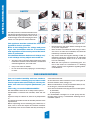
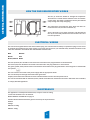
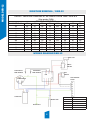
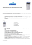
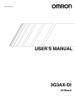
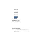
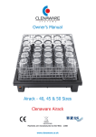
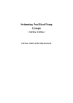
DEHUMIDIFIERS GENERAL INFORMATION DSR SERIES EXPLODED VIEWS DSR-20 DSR-12 PARTS LISTS ENGLISH ATTENTION! 0912R1 There is a time delay on all units fitted with ‘DFC 1’ Controller. When starting or restarting the unit, it could take up to 3 minutes for the fan and compressor to start running. GENERAL INFORMATION SAFETY For safety reasons, read this information carefully before operating. Persons who are not familiar with this type of product must not use it. We strongly recommend keeping this information in a safe place for future reference. This appliance must be earthed. The unit is designated for indoor operation. Refer to the rating plate for voltage and power input. The installation must be in accordance with regulations of the country where the installation is performed. The minimum distance between air inlet(s) and/ or air outlet(s) and any object must be 40 cm. • Do not insert any object into an opening of the unit. • Disconnect from the mains before cleaning the unit or any of its components. • Never connect to an electrical outlet using an extension cord. If an outlet is not available, one should be installed by a licenced electrician. • Any service other than regular cleaning or filter replacement should be performed by an authorized service representative. Failure to do so could result in a loss of warranty. • When the unit is placed in a (swimming) pool, connect to the mains via a transformer or a breaking switch, conform to the regulations regarding electrical installations. • The unit is safe. It has been approved by many safety institutions around the world. However, as with other electrical appliances, use it with care. • Keep out of reach of children. • Do not clean the unit by spraying it or immersing it in water. DSR DEHUMIDIFIERS You can’t control humidity and haze outdoors. But in an indoor swimming pool and other humid interior spaces where hot stuffy air, steamy windows and walls are frequent phenomena, you can. That’s why you need a DSR dehumidifier. often found in the hall. At the same time water condenses on the cooler parts in the hall: windows, walls, ceilings, etc. Water condensation is not only an aesthetic defect, it can, in the long run, cause structural damage. There are two methods for drying the air in humid spaces: - by ventilation, - by heat pumps. Our dehumidifier is designed as a heat pump and has, through energy saving, a considerable advantage over a ventilation system. Our dehumidifiers clear the air in damp interior spaces. Condensation is removed from windows, walls and ceilings. Vaporous stuffy air is drawn off, clean air is pumped back in. You simply set the dial and the air humidity remains at the required level. Water evaporating from a swimming pool, bathroom, archive, store or from wet objects and surfaces increases the humidity of the air and creates the hazy and stuffy air 2 GENERAL INFORMATION HOW THE DSR DEHUMIDIFIER WORKS The fan (1) sucks the humid air through the evaporator. There the air is cooled and the moisture in the air condenses into water. This water is collected in the tray and drained away through the sump and piping. The compressor (5) pumps the heat, which has been extracted from the air, into the condenser (6). There, this heat is once again released, and absorbed by the dry air. The ready wired control box monitors and controls the operation. ELECTRICAL WIRING The unit can be supplied with a cord and an earthed plug. If it ever becomes necessary to replace this plug, be sure to use an earthed plug suitable for the power supply in your area and conform to your national safety standard. The wires of the cable are coloured in accordance with the standard electrical code. Blue Neutral Brown Live Green/Yellow Earth The blue (neutral) wire should be connected to the terminal in the plug marked N or coloured black. The brown (live) wire should be connected to the terminal in the plug marked L or coloured red. The green/yellow (earth) wire should be connected to the terminal in the plug marked E or coloured green or marked with this symbol: The unit must be connected to the power supply with the appropriate leads. The cord should pass through holes with rubber grommets. Properly fused disconnect switches must be installed between the unit and the power source. The unit must be wired with an isolation (mains) switch accessible from outside the wet area in which the unit is installed, to comply with IEE regulations. MAINTENANCE The appliance is actually maintenance free, except in cases of soiling. In this case the filter has to be cleaned. Models DSR-12 and DSR-20 see page 4 Contains Flouronated Greenhouse gasses covered by the Kyoto Protocol R410A Charge: DSR-12= 1.25kg DSR20= 1.5kg 3 GENERAL INFORMATION DSR INDOOR SWIMMING POOL ROOM DEHUMIDIFIERS Our swimming pool dehumidifier is a ready to install, transportable, appliance. It can be mounted on a wall or ceiling console in the pool room or even over a shower booth. It may be mounted in adjoining rooms and connected by ducts to the pool room. We have not adapted normal room air-conditioners for use in indoor swimming pools, we have developed pool dehumidifiers particularly for this purpose. The compressor therefore matches exactly the capacity of the evaporator, thus achieving the optimal balance between efficiency and power consumption. The pool dehumidifier is controlled by a humidistat which operates at a low (=safety) voltage of 24V. The relative humidity in an indoor swimming pool can be adjusted between 50-80% when an external hygrostat is used. INSTALLING THE DSR The minimum distance between inlet(s) and/or outlet(s) and any object must be 40 cm. Installation of the dehumidifier is easy, as the unit is built on a base and slides out of the housing. The individual parts are logically arranged and can be inspected. First, remove the screws of the frame with louvers. Remove the screws on the base. Now the unit can be taken out the housing. Prepare a suitable console and mount it on the wall. Mount the housing on the console and attach it by fastening its base with screws to the legs (which should preferably be lagged with a vibration dampening material). Insert the unit into the housing, fasten the housing to the base and attach the louvered frame in front of the housing. Attach a 3/4” I.D. flexible pipe to the drain nipple located at the back of the dehumidifier. MAINTENANCE The appliance is actually maintenance free, except in cases of soiling. In this case the filter has to be cleaned. INLET To remove the filter, slide open the 2 latches that hold the filter grille, located at the back of the unit. Swing the grille towards you and upwards to access the filter. Remove the filter. Use a vacuum cleaner to remove dust and debris. The filter can then be flushed clean with a stream of water. Let any trapped water drip off the filter fabric and allow to OUTLET dry. Replace the dried filter in reverse order. OPERATING RANGE Max. working temperature Min. working temperature Relative humidity 1/2”BSP 4 35°C 5°C 40-100% MODEL DSR-12 MOISTURE REMOVAL / DSR-12 DSR-12 - MOISTURE REMOVAL AT DIFFERENT ROOM TEMP. EN R.H.% (liter water/24h) RELATIVE HUMIDITY % ROOM TEMP. °C 15 20 24 25 26 27 28 29 30 32 35 85 41 57 73 77 80 84 88 92 96 100 104 80 37 52 66 70 73 77 80 84 87 91 94 75 34 48 60 63 67 70 73 76 79 82 86 70 31 43 55 58 60 63 66 69 72 75 78 65 28 38 49 51 54 56 59 62 64 67 69 60 25 34 43 46 48 50 52 55 57 59 62 55 23 30 39 41 43 45 47 49 51 53 55 50 17 27 34 36 38 40 42 43 45 47 49 WIRING DIAGRAM DSR-12 JACK PLUG SMALL SWITCH EVAPORATOR CONDENSER TEMP SENSOR TEMP SENSOR FAN SWITCH PCB FAN TERMINAL COMPRESSOR BLOCK CAPACITOR MAINS LEAD EARTH POST 5 SYMBOL COLOUR BL BLUE BK BLACK G/Y GREEN/ YELLOW R RED WT WHITE BASE PANEL ASSY DH02-A001 DH02-A003 DH02-C017 DH02-A004 DH02-C012 DH02-C011 DH02-P021 DH02-P004 DH02-C006 DH02-C049 DH02-P003 DH02-C008 DH02-C013 DH02-A010 DH02-A009 DH02-P029 DHO2-P021 DH01-P003 DH02-C047 DH02-C048 DH02-PO33 DH02-P032 1 2 3 4 5 6 7 8 9 10 11 12 13 14 15 16 17 18 19 20 21 22 ROCKER SWITCH SMALL JACK SOCKET COIL BRACE LEFT COIL BRACE RIGHT ROCKER SWITCH FILTER MATERIAL COMPRESSOR CAPACITOR COVER ASSY PCB FAN HOUSING EVAP TOP COVER EVAPORATOR COIL EVAP MOUNT BRACKET RIGHT EVAP MOUNT BRACKET LEFT CONDENSER COIL COMPRESSOR INNER PANEL LH INNER PANEL RH FAN FAN HOUSING MOUNTING BRACKET DRAIN TRAY ASSY DESCRIPTION No. PART No ASSEMBLY PART PART PART ASSEMBLY PART PART ASSEMBLY ASSEMBLY PART PART PART PART PART PART PART PART PART PART PART ASSEMBLY ASSEMBLY TYPE 1 1 1 1 1 1 1 1 1 1 1 1 1 1 1 1 1 1 1 1 1 1 QTY 6 COVER COVER OUTLET END PANEL REAR PANEL ASSY DH02-C030 DH02-C021 DH02-A007 DH02-C026 DH02-P027 DH01-P004 DH02-P021 1 2 3 4 5 6 7 FILTER MATERIAL LATCH HANDLE FILTER DOOR DESCRIPTION No. PART No PART PART PART 1 2 4 1 1 PART 1 ASSEMBLY 1 QTY PART PART TYPE MODEL DSR-12 EXPLODED VIEW DSR 12 MODEL DSR-20 MOISTURE REMOVAL / DSR-20 DSR-12 - MOISTURE REMOVAL AT DIFFERENT ROOM TEMP. EN R.H.% (liter water/24h) RELATIVE HUMIDITY % ROOM TEMP. °C 15 20 24 25 26 27 28 29 30 32 35 85 69 96 121 128 134 141 147 153 160 166 173 80 62 87 110 116 122 128 134 139 145 151 157 75 57 79 100 106 111 116 121 127 132 137 143 70 52 72 91 96 101 106 110 115 120 125 130 65 46 64 81 85 90 94 98 103 107 111 116 60 41 57 72 76 80 84 87 91 95 99 103 55 23 51 64 68 71 74 78 81 85 88 92 50 17 45 57 60 63 66 69 72 75 78 82 WIRING DIAGRAM DSR-20 JACK PLUG SMALL SWITCH EVAPORATOR CONDENSER TEMP SENSOR TEMP SENSOR FAN SWITCH PCB FAN TERMINAL COMPRESSOR BLOCK CAPACITOR MAINS LEAD EARTH POST 7 SYMBOL COLOUR BL BLUE BK BLACK G/Y GREEN/ YELLOW R RED WT WHITE BASE PANEL ASSY DH02-A001 DH02-A003 DH02-C017 DH02-A004 DH02-C012 DH02-C011 DH02-P021 DH02-P001 DH02-C006 DH02-C007 DH02-P002 DH02-C008 DH02-C013 DH02-A010 DH02-A009 DH02-P013 DHO2-P021 DH01-P003 DH02-C047 DH02-C048 DH02-PO33 DH02-P032 1 2 3 4 5 6 7 8 9 10 11 12 13 14 15 16 17 18 19 20 21 22 ROCKER SWITCH SMALL JACK SOCKET COIL BRACE LEFT COIL BRACE RIGHT ROCKER SWITCH FILTER MATERIAL COMPRESSOR CAPACITOR COVER ASSY PCB FAN HOUSING EVAP TOP COVER EVAPORATOR COIL EVAP MOUNT BRACKET RIGHT EVAP MOUNT BRACKET LEFT CONDENSER COIL COMPRESSOR INNER PANEL LH INNER PANEL RH FAN FAN HOUSING MOUNTING BRACKET DRAIN TRAY ASSY DESCRIPTION No. PART No ASSEMBLY PART PART PART ASSEMBLY PART PART ASSEMBLY ASSEMBLY PART PART PART PART PART PART PART PART PART PART PART ASSEMBLY ASSEMBLY TYPE 1 1 1 1 1 1 1 1 1 1 1 1 1 1 1 1 1 1 1 1 1 1 QTY 8 COVER COVER OUTLET END PANEL REAR PANEL ASSY DH02-C030 DH02-C021 DH02-A007 DH02-C026 DH02-P027 DH01-P004 DH02-P021 1 2 3 4 5 6 7 FILTER MATERIAL LATCH HANDLE FILTER DOOR DESCRIPTION No. PART No PART PART PART 1 2 4 1 1 PART 1 ASSEMBLY 1 QTY PART PART TYPE MODEL DSR-20 EXPLODED VIEW DSR-20 9 CONTACT