1
LD2
Operations Manual
VERIPOS
_____________________________________________________________________
Doc. No. AB-V-MA- 00512 LD2 Operations Manual_RevD.doc
6.9.2013 For Customer Release
Originator AW
Checked RR
Approved EM
Table of Contents
LD2 Operations manual
AB-V-MA-00512
1
Introduction .................................................................................................... 3
1.1
VERIPOS ................................................................................................. 3
1.1.1
Veripos .............................................................................................. 3
1.1.2
LD2 ................................................................................................... 3
1.2
Scope and safety ..................................................................................... 4
1.2.1
Safety ................................................................................................ 4
1.3
Target groups .......................................................................................... 4
1.4
Contents .................................................................................................. 5
1.5
Terms and abbreviations ......................................................................... 6
1.6
Document conventions ............................................................................ 8
1.6.1
Typographical conventions ............................................................... 8
1.6.2
Special notices .................................................................................. 8
1.7
Accessories supplied with the unit ........................................................... 9
1.8
VERIPOS Helpdesk ................................................................................. 9
1.9
VERIPOS online support (VOSS) .......................................................... 10
1.10 Enabling the equipment for use ............................................................. 10
1.11 Specification .......................................................................................... 11
1.12 Essential operation tasks ....................................................................... 11
1.13 Disclaimer .............................................................................................. 12
2
Operation ...................................................................................................... 13
2.1
User interface ........................................................................................ 13
2.1.1
Front panel ...................................................................................... 13
2.1.2
Rear panel ...................................................................................... 15
2.1.3
Serial ports and VGA connector ..................................................... 18
2.1.4
Power socket with on/off switch ...................................................... 19
2.2
Main menu structure .............................................................................. 19
2.2.1
Main menu ...................................................................................... 20
2.3
Operating procedures ............................................................................ 21
2.3.1
Initial start up of LD2 ....................................................................... 21
2.3.2
Enabling and disabling the LD2 ...................................................... 24
2.3.3
Checking demodulator status ......................................................... 27
2.3.4
Configuring LD2 demodulator to receive corrections ...................... 29
2.3.5
Available reference stations ............................................................ 33
2.3.6
Configuring demodulator channel 16 .............................................. 35
2.3.7
Checking GPS status ...................................................................... 38
2.3.8
Configuring RTCM output ports ...................................................... 42
2.3.9
Configuring position output from port P1 ........................................ 45
2.3.10 Configure to receive VERIPOS HF corrections .............................. 49
2.3.11 Reconfiguring for a new location .................................................... 54
2.3.12 Determining firmware versions ....................................................... 55
2.3.13 Configuring a 1 pps output from the LD2 ........................................ 56
2.4
System test ............................................................................................ 58
2.5
System information ................................................................................ 58
2.5.1
PC/104 S/W .................................................................................... 59
2.5.2
Installed H/W .................................................................................. 59
2.5.3
Host IP address .............................................................................. 59
2.6
Access code .......................................................................................... 60
2.6.1
Model variant .................................................................................. 60
2.6.2
Checking current status .................................................................. 60
2.6.3
Determine current access code ...................................................... 60
2.6.4
Request enable/disable code ......................................................... 60
2.7
Reference information ............................................................................ 61
2.7.1
Menu structure ................................................................................ 61
2.7.2
Configuration mode ......................................................................... 74
2.7.3
Serial ports configuration ................................................................ 82
2.7.4
Unit status ....................................................................................... 97
2.7.5
GPS receicer menu ....................................................................... 102
2.7.6
NMEA 0183 messages ................................................................. 109
2.7.7
Global coverage chart ................................................................... 116
2.8
Bridge cards ......................................................................................... 117
2.8.1
LD2 – Access code ....................................................................... 117
2.8.2
LD2 – Beam selection, select data channel .................................. 119
2.8.3
LD2 – Configuration of RTCM port outputs ................................... 121
2.8.4
LD2 – Configuration of position output on port P1 ........................ 122
2.8.5
LD2 – Configuration of VERIPOS HF corrections ......................... 124
2.8.6
LD2 – Checks of equipment status ............................................... 126
2.9
Specifications ....................................................................................... 128
2.9.1
LD2 specifications ......................................................................... 128
2.10 GNSS, Ports, SAL and SNF ................................................................. 133
2.10.1 I/O port details ............................................................................... 133
2.10.2 Signal access licence and service notification form ...................... 134
3
Troubleshooting ......................................................................................... 139
3.1
Power fault ........................................................................................... 140
3.2
Enable/disable faults ............................................................................ 141
3.3
L-band signal fault ................................................................................ 142
4
Contact information ................................................................................... 143
4.1
VERIPOS UK ....................................................................................... 143
4.1.1
Helpdesk ....................................................................................... 143
4.2
Additional VERIPOS offices: ................................................................ 144
LD2 Operations manual
AB-V-MA-00512
1 Introduction
1 Introduction
1.1
VERIPOS
This manual contains the information required to operate the Veripos LD2
unit.
1.1.1
Veripos
Veripos specialise in providing robust data broadcast services for precise
positioning applications for the offshore industry. For optimum performance
it is essential that the receiving and processing hardware is of an equally high
standard.
To ensure this, Veripos offers a range of hardware designed and manufactured to the highest specifications, and with relevant certifications.
1.1.2
LD2
The LD2 integrated mobile unit is designed to achieve the product philosophy of standardised, upgradeable hardware with maximum flexibility whilst
beeing simple to operate and maintain.
The LD2 is available in a number of configurations from basic satellite
receiver to a fully integrated mobile positioning unit with demodulator and
multi-frequency GNSS receiver. Completely modular, the unit can be
upgraded to different configurations as required. Functionally, the LD2 can
be used in a virtual “black box” mode to generate any Veripos proprietary
position solution, depending upon the data subscriptions enabled.
Additionally it can be used as a sensor to output received data and GNSS
measurements to external processing or quality control software such as
Veripos’ Verify QC suite.
A small LCD and a keypad allow for quick and easy user setup. In addition
to calculating position the LD2 is able to output all received data in standard
formats such as RTCM and NMEA. The LD2 is exceptionally flexible and in
most configurations overall operating status can be determined via the LED
indicators and the LCD.
For more comprehensive status indication, the LD2 may optionally be
equipped with onboard QC software Verify DP, which has been optimised for
DP operations. The software gives the user basic QC displays such as tracked
satellite signal to noise ratio's, polar plot of satellites in view, current and predicted DOP levels, reference station information as well as Service subscription indicators and warning alarms. The operation of Verify DP software is
documented in a separate manual.
VERIPOS transmit DGPS corrections from geostationary satellites. Highpower transmissions can be received using a compact high-gain omni-directional spot antenna.
Low-power transmissions can only be received using a suitable stabilized
dish antenna. If the vessel is fitted with an Inmarsat communication system
this can generally be utilised by installing an interfacing kit.
LD2 Operations manual
AB-V-MA-00512
3(144)
1 Introduction
Advanced yet robust, easy to install and operate, the Veripos LD2 is an
outstandingly effective and flexible unit that ensures reliable reception of
Veripos services, as well as producing superior positioning from metre to
decimetre level accuracy.
Further information on the LD2 and related products can be found on the
VERIPOS VOSS (details later in this section), including knowledge base,
quick guides and FAQ’s.
Where required, see the LD2 Installation manual, Verify DP Operations
manual and Veripos Verify QC manual.
1.2
Scope and safety
This manual contains the information required for the operation of the
Veripos LD2 unit. For information on the operation of Verify DP see the
Verify DP Operations manual. Information on related products can be found
in the Veripos Verify QC User manual.
Manuals are available at: http://help.veripos.com
1.2.1
Safety
Safety is the responsibility of the individual carrying out the work and all
persons involved in the operation.
•
•
•
•
1.3
On arrival at the worksite contact the wheel house for a site specific
safety induction.
Follow safety rules applying at the work site.
Obtain all permits relevant to the job prior to any work commencing.
Were necessary the safety check-list should be completed, if applicable.
Target groups
The target group for the this manual are the operators of the Veripos LD2
unit.
4(144)
LD2 Operations manual
AB-V-MA-00512
1 Introduction
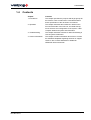
1.4
Contents
LD2 Operations manual
AB-V-MA-00512
Chapter
Contents
1. Introduction
This chapter specifies the purpose and target groups for
the manual. It also contains list of used abbreviations
and a specification of the document conventions.
2. Operation
This chapter describes the interfaces in detail on the
front and back side of the LD2 unit, the initial start-up,
menu structure and configuration of the system. It also
comprise status and system test information.
3. Troubleshooting
This chapter describes routines for basic fault-finding in
case of system malfunction.
4. Contact Information
This chapter contains information about how to contact
the VERIPOS Helpdesk regarding technical or support
issues. It also contains addresses to additional
VERIPOS offices world wide.
5(144)
1 Introduction
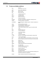
1.5
6(144)
Terms and abbreviations
A
Ampere
ADE
Above Deck Equipment
BDE
Below Deck Equipment
BER
Bit Error Rate
bps
Bits Per Second
CoG
Course Over Ground
CR
Carriage Return
DGPS
Differential GPS
DOP
Dilution of Precision
DP
Dynamic Positioning
EGNOS
European Geostationary Navigation Overlay Service
GDOP
Geometry Dilution of Precision
GLONASS
Global Navigation Satellite System - Russian equivalent to
GPS
GPS
Global Positioning System
GNSS
Global Navigation Satellite System
HDOP
Horizontal Dilution of Precision
HF
High Frequency Radio used to transmit correction data
Hz
Hertz
KPH
Kilometers per Hour
LAN
Local Area Network
LED
Light Emitting Diode
LF
Line Feed
LNA
Low Noise Amplifier
L-band
Methods of transmitting correction data to mobile users
LCD
Liquid Crystal Display
LD2
Unit containing GPS card, demodulator and PC processor
MF
Medium Frequency Radio used to transmit correction data
MHz
Mega-Hertz
MPH
Miles per Hour
m/s
Meter per second
NMEA
National Marine Electronics Association
N/A
Not applicable
PDOP
Positional Dilution of Precision
PPP
Precise Point Positioning
PPS
Pulse per Second
PRN
Pseudo Random Noise
RMS
Root Mean Square
RoHS
Restrictions on the use of certain Hazardous Substances in
electrical and electronic equipment.
RTCM
Radio Technical Commission for Maritime Services
LD2 Operations manual
AB-V-MA-00512
1 Introduction
SAL
Service Access Licence
SD
Standard Deviation
SNF
Signal Notification Form
SNR
Signal to Noise Ratio
Spotbeam
High Power L-Band Signal
Standard / Std
Veripos Single Frequency DGPS System
Standard+ / Std+ Veripos Dual Frequency DGPS System
LD2 Operations manual
AB-V-MA-00512
SV
Space Vehicle
TDR
Time Domain Reflectometer
TTL
Transistor-Transistor Logic
Type 01
Single Frequency Corrections
Type 15
Dual Frequency Correction
Ultra /APEX
Veripos High Accuracy Positioning Systems
USB
Universal Serial Bus
UTC
Coordinated Universal Time
V
Volt
VDOP
Vertical Dilution of Precision
VERIPOS
Global DGPS Service Provider
VGA
Video Graphic Array
VOSS
VERIPOS Online Support System
W
Watt
WAAS
Wide Area Augmentation System
WEEE
Waster Electrical and Electronic Equipment
7(144)
1 Introduction
1.6
Document conventions
1.6.1
Typographical conventions
Italic text is used to emphasize certain parts of the information as well as in
cross-references to other parts of the document.
Bold text is used for push-button commands in the keypad.
“Text within quotes” is used when displaytexts are mentioned in text
Monospace text is used for output strings from the device.
1.6.2
Special notices
WARNING
A warning indicates the risk of bodily harm or serious damage
to the hardware.
CAUTION
A caution indicates the risk of damaging the hardware.
NOTE
A note shows important information that helps you make better use of the
system.
8(144)
LD2 Operations manual
AB-V-MA-00512
1 Introduction
1.7
Accessories supplied with the unit
The LD2 is supplied with documentation and equipment as agreed with the
user.
Typically this will include:
•
•
•
•
equipment packing list showing a list of the equipment supplied
LD2 receiver variant
LD2 manuals and reference material on CD
antenna(s), coaxial, cables and connectors.
Optionally depending upon the variant supplied:
•
•
•
screen and keyboard/mouse for use with software e.g. Verify DP
rack housing VERIPOS equipment
connection equipment & cabling.
To aid the user VERIPOS recommend Verichart software to plot regional
operational coverage charts. Verichart can aid when selecting beams and stations. It also provides azimuth and elevation information for geo-stationary
satellites – useful for predictions.
Verichart may be downloaded from VOSS (see below for details).
1.8
VERIPOS Helpdesk
VERIPOS encourage all users to promptly report problems or operating queries to the Helpdesk so that they may receive assistance.
The VERIPOS Helpdesk is the first point of contact for technical enquiries
and fault reports. It is manned 24 hours per day, 365 days per year.
Helpdesk contact details are in the “Operation” chapter.
For assistance with basic troubleshooting see the “Troubleshooting” chapter.
We recommend initial contact is made by email to the Helpdesk.
Users can also create a fault ticket on the Web site. This will ensure contact
details and the description of the fault are correctly recorded.
The duty operator is trained to provide direct assistance with most queries
and problems and can request technical staff to provide support for more
complex issues.
LD2 Operations manual
AB-V-MA-00512
9(144)
1 Introduction
1.9
VERIPOS online support (VOSS)
VERIPOS have an online customer support system called VOSS (VERIPOS
online support system).
VERIPOS recommend users frequently view the announcements made on
this system.
VOSS includes a facility for raising fault tickets which are then automatically submitted to the VERIPOS Helpdesk.
The VOSS url is: http://help.veripos.com
VOSS has comprehensive help and assistance that provides:
•
•
•
•
•
updates on VERIPOS service availability and notifications
knowledge base
troubleshooter
downloads
online fault reporting.
1.10 Enabling the equipment for use
VERIPOS correction signals are provided as a chargeable service.
In order for the equipment to decode corrections and output positions it must
be enabled.
This is achieved by the user entering an access code supplied by the
VERIPOS Helpdesk.
When not in use some contracts may allow for disabling the service.
The enable/disable procedure is detailed in the “Operation” chapter.
NOTE
To use VERIPOS correction signals a contract between the user's company
and the VERIPOS Operations department must be in place. VERIPOS call
this a service access license (SAL).
To avoid delays users should record the SAL number associated with the
VERIPOS equipment.
The Helpdesk is not authorised to issue a code unless an active SAL exists
and its reference number can be determined.
10(144)
LD2 Operations manual
AB-V-MA-00512
1 Introduction
1.11 Specification
An equipment specification is included in the “Operation” chapter.
The LD2 is available in a range of variants. The options included in each unit
are indicated by its model number:
L X D X -XXX
G1 - L1 GPS Receiver Option
G2 - L1/L2 GPS Receiver Option
GG1 - L1 GPS & GLONASS Reception Option
GG2 - L1/L2 GPS & GLONASS Reception Option
2 - Series 2 Receiver
2S - Series 2 Receiver with second generation L-Band card
Demodulator
- No Optional RF Receiver Installed
H - VERIPOS HF & MF Receiver Installed
I - IALA MF Receiver Installed
L - Band Receiver Installed
i.e. an LHD2-GG2 mobile receiver is capable of L-Band, HF/MF, L1/L2
GPS and GLONASS reception.
1.12 Essential operation tasks
This manual provides the user with the information required for the configuration, operation and monitoring of the VERIPOS LD2 integrated mobile
unit.
The “Operation” chapter provide a description of each menu function.
All LD2 configuration and monitoring is performed using the front panel
two-line LCD and a 3-key switch pad using menu system.
The only additional controls are two toggle switches mounted on the rear
panel.
The “Operation procedures” section of the “Operation” chapter provides step
by step instructions for performing the most common tasks. It is recommended as a good starting point for new users or when commissioning an
installation.
The procedures have been summarised in “Quick Guide” format to assist the
user in performing common tasks, downloaded from VeriposVOSS.
VOSS is available at http://help.veripos.com
LD2 Operations manual
AB-V-MA-00512
11(144)
1 Introduction
Topics covered include:
•
•
Enabling the required VERIPOS services
Beam selection - select data channel
•
•
•
•
Configuration of RTCM port outputs
Configuration of Position output on P1
Configuration of VERIPOS HF corrections
Checks of Equipment status.
1.13 Disclaimer
VERIPOS accepts no responsibility for any damage or injury to the system,
ship or personnel caused by drawings, instructions or procedures not prepared by VERIPOS.
Copyright © 2013 by VERIPOS. All rights reserved.
All rights reserved. No part of this manual may be reproduced without prior
written permission from VERIPOS.
Contents of this manual are subject to change without notice.
Every effort has been made to ensure accuracy of the information contained
within this manual. Please advise VERIPOS of errors you may encounter.
Thank you.
VERIPOS assume no responsibility for errors or omissions contained within
this manual.
12(144)
LD2 Operations manual
AB-V-MA-00512
2 Operation
2 Operation
2.1
User interface
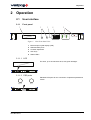
2.1.1
Front panel
1
2
3
4
Page
5
Toggle
DC Supply
Enter
Sync
HF/MF Lock
ID
GPS
Message
DGPS
Contrast
LD2S integrated positioning mobile
Keyboard
Mouse
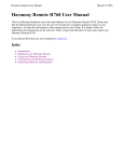
Figure 1. LD2 Front Panel View
1 Back lit liquid crystal display (LCD)
2 Standard PS/2 ports
3 Contrast adjustment
4 User keys
5 Status LED’s
2.1.1.1 LCD
Two lines, up to 20 character each, with green backlight.
Page
Toggle
DC Supply
Enter
Sync
LD2 integrated positioning mobile
HF Lock
ID
GPS
Message
DGPS
Contrast
Keyboard
Mouse
2.1.1.2 PS/2 ports
Standard PS/2 ports for the connection of optional keyboard and
mouse.
Keyboard
Mouse
Page
Toggle
DC Supply
Enter
Sync
LD2 integrated positioning mobile
HF Lock
ID
GPS
Message
DGPS
Contrast
Keyboard
Mouse
LD2 Operations manual
AB-V-MA-00512
13(144)
2 Operation
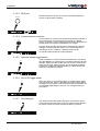
2.1.1.3 Contrast adjustment
A small flat headed screwdriver can be used to adjust the screen
contrast as desired. Turn clockwise to increase.
Contrast
Page
Toggle
DC Supply
Enter
HF Lock
Sync
ID
GPS
Message
DGPS
Contrast
LD2 integrated positioning mobile
Keyboard
Mouse
2.1.1.4 User keys
Page key:
Page
Toggle
Enter
Advances the display through the options in a menu
level. After the last menu option in the current menu
level, the display moves back to the entry point of
that menu.
Toggle key: Shows the range of data entries available in a menu
Enter key: Displays the selected menu option, accepts a data
entry and advances the display to the next data entry
field.
Page
Toggle
DC Supply
Enter
Sync
HF Lock
ID
GPS
Message
DGPS
Contrast
LD2 integrated positioning mobile
Keyboard
Mouse
2.1.1.5 Status LED’s
DC Supply
Illuminated when LD2 is locked onto the downlink
beam.
ID:
Illuminated when LD2 is enabled for service.
Flashing when LD2 is disabled. Off when LD2 has
never been enabled.
Message:
lluminated when a message has been received
from the VERIPOS Helpdesk.
IF Lock:
Present on older LD2's. Illuminated when using a
70 MHz antenna system and signal lock is
detected in the internal upconverter. Not currently
implemented. The IF lock LED is in the same location as that of the HF lock LED on more recent
models of LD2.
HF Lock
Sync
ID
GPS
Message
DGPS
Page
Toggle
DC Supply
Enter
Sync
LD2 integrated positioning mobile
Sync:
HF Lock
ID
GPS
Message
DGPS
Contrast
Keyboard
Mouse
HF/MF Lock: Present on newer LD2's. Illuminated when the
internal HF/MF demodulator has signal lock.
14(144)
GPS:
Illuminated when the GNSS card is outputting a
non differential GGA telegram through port 1.
Flashing indicates the number of satellites used
in the position computation. Can be intentionally
switched off in some configurations/applications.
DGPS:
Illuminated when the GNSS card is outputting a
differentially corrected GGA telegram through
Port 1. Can be intentionally switched off in some
configurations/applications.
Power:
Illuminated when the internal DC power supply is
activated.
LD2 Operations manual
AB-V-MA-00512
2 Operation
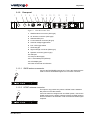
2.1.2
1
Rear panel
2
GPS
3
4
HF ANT
MSE/KBD
5 6
L-BAND
78
ANT.V PORT 3
ON
GPS
9 10 11 12
SPEAKER
13
P2
P4
P5
P1
P3
P6
14
85-264 VAC FUSE 1A
USB
O
SIG LVL
OFF REM I/O
LAN
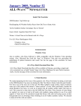
Figure 2. LD2 Rear Panel View
1 GNSS antenna connector (TNC-type)
2 HF antenna connector (TNC-type)
3 Standard PS/2 port
4 L-band antenna connector (N-type)
5 Antenna voltage toggle switch
6 Port 3 I/O toggle switch
7 Grounding pin
8 Signal strength connector (SMA-type)
9 Speaker connector (phono-type)
10 USB port
11 LAN port RJ45-type)
12 5 x serial data ports (RS-232)
13 VGA display port
14 Power socket with on/off switch
2.1.2.1 GNSS antenna connector
Connect the GPS/GNSS antenna here. This is the antenna that is
used to receive GPS/GNSS signals. Do not stress connector.
GPS
GPS
HF ANT
SPKR
L-BAND
ANT.V PORT 3
ON
GPS
SIG
STRENGTH
P2
P4
P5
P1
P3
P6
85-264 VAC FUSE 1A
USB
O
OFF REM I/O
LAN
2.1.2.2 HF/MF antenna connector
This input is only present only where a HF/MF card is installed.
Not present on all LD2 variants.
HF ANT
If the LD2 variant is configured for an HF/MF system, connect the
HF/MF antenna here. HF/MF systems require the HF/MF antenna
and LD2 chassis to be earthed in order to maximize HF/MF signal
reception.
GPS
HF ANT
SPKR
L-BAND
ANT.V PORT 3
ON
GPS
SIG
STRENGTH
P2
P4
P5
P1
P3
P6
85-264 VAC FUSE 1A
USB
O
OFF REM I/O
LAN
LD2 Operations manual
AB-V-MA-00512
15(144)
2 Operation
2.1.2.3 PS/2 port
Standard PS/2 port for the connection of optional keyboard or
mouse (requires PS/2 Y splitter).
MSE/KBD
GPS
HF ANT
MSE/KBD
L-BAND
SPEAKER
ANT.V PORT 3
ON
GPS
P2
P4
P5
P1
P3
P6
85-264 VAC FUSE 1A
USB
O
SIG LVL
OFF REM I/O
LAN
2.1.2.4 L-band antenna connector
Connect either an L-band omni directional spot beam antenna or
the line feed from an Inmarsat system coupler (e.g. Narda,
Rojone or Radiall). Some Inmarsat systems have a dedicated output that does not require the installation of a coupler.
L-BAND
In some cases the LNA feed should be switched off to prevent
damage to vessel Inmarsat system. In the LD2S variant this
switching is done in software – detailed in this manual.
GPS
HF ANT
SPKR
L-BAND
ANT.V PORT 3
ON
GPS
SIG
STRENGTH
P2
P4
P5
P1
P3
P6
85-264 VAC FUSE 1A
USB
O
OFF REM I/O
LAN
All coaxial cables should be 50 W impedance.
2.1.2.5 Antenna voltage toggle switch
Used to disable the 5 VDC antenna LNA feed when connecting
the LD2 VARIANT to certain types of Inmarsat systems to prevent
damage. Where the LD2 variant does not have the switch a DC
block may be used. When using an omni-directional spotbeam
antenna the voltage should be enabled. For LD2S variants this
needs to be enabled in software.
ANT.V
ON
OFF
GPS
HF ANT
SPKR
L-BAND
ANT.V PORT 3
ON
GPS
SIG
STRENGTH
P2
P4
P5
P1
P3
P6
85-264 VAC FUSE 1A
USB
O
OFF REM I/O
LAN
2.1.2.6 Port 3 I/O toggle switch
When the switch is in the GPS position, raw GPS data is output
from the GPS card. When in the REM I/O position either NMEA
messages can be output or new firmware for the demodulator can
be uploaded (depending on how port 3 is configured from the
front panel).
PORT 3
GPS
REM I/O
GPS
HF ANT
SPKR
L-BAND
ANT.V PORT 3
ON
GPS
SIG
STRENGTH
P2
P4
P5
P1
P3
P6
85-264 VAC FUSE 1A
USB
O
OFF REM I/O
LAN
2.1.2.7 Grounding pin
The chassis of the LD2 variant should be connected to vessel
ground and is important when using HF systems where both the
HF antenna and LD2 variant chassis should be grounded.
GPS
HF ANT
SPKR
L-BAND
ANT.V PORT 3
ON
GPS
SIG
STRENGTH
P2
P4
P5
P1
P3
P6
85-264 VAC FUSE 1A
USB
O
OFF REM I/O
16(144)
LAN
LD2 Operations manual
AB-V-MA-00512
2 Operation
2.1.2.8 Signal strength connector
This is not used. (To provide a feedback line to a tracking dish
type antenna such as a Minidome, Inmarsat systems do not usually require signal strength feedback).
SIG
STRENGTH
GPS
HF ANT
SPKR
L-BAND
ANT.V PORT 3
ON
GPS
SIG
STRENGTH
P2
P4
P5
P1
P3
P6
85-264 VAC FUSE 1A
USB
O
OFF REM I/O
LAN
2.1.2.9 Speaker connector
Only used in Verify DP applications where an external speaker is
required for the alarm.
SPKR
GPS
HF ANT
SPKR
L-BAND
ANT.V PORT 3
ON
GPS
SIG
STRENGTH
P2
P4
P5
P1
P3
P6
85-264 VAC FUSE 1A
USB
O
OFF REM I/O
LAN
2.1.2.10 USB port
The USB connector can be used to input external data e.g. gyro.
USB
GPS
HF ANT
SPKR
L-BAND
ANT.V PORT 3
ON
GPS
SIG
STRENGTH
P2
P4
P5
P1
P3
P6
85-264 VAC FUSE 1A
USB
O
OFF REM I/O
LAN
2.1.2.11 LAN port
Used to network the LD2 so that data can be broadcast over TCP/
IP sockets.
LAN
GPS
HF ANT
SPKR
L-BAND
ANT.V PORT 3
ON
GPS
SIG
STRENGTH
P2
P4
P5
P1
P3
P6
85-264 VAC FUSE 1A
USB
O
OFF REM I/O
LAN
LD2 Operations manual
AB-V-MA-00512
17(144)
2 Operation
2.1.3
GPS
HF ANT
SPKR
L-BAND
ANT.V PORT 3
ON
GPS
Serial ports and VGA connector
SIG
STRENGTH
P2
P4
P5
P1
P3
P6
P2
P4
P5
P1
P3
P6
Port 1 – D9
Female
Port 1 is the primary NMEA output for position
either from the LD2 processor or GNSS card.
For ZDA with 1PPS use P1 to output from GNSS card.
Port 2 – D9
Female
Port 2 is the primary RTCM output and is used for
internal connections by the processor algorithms.
The processor card is capable of utilizing 4 stations
in this way.
.
.
.
.
.
Port 3 – D9
Female
Port P3 is used for the remote control of the GPS
Receiver and the Demodulator Board.
85-264 VAC FUSE 1A
USB
O
OFF REM I/O
LAN
GPS Gives Raw GPS out when the Port 3 switch on
the back panel of the LD2 is in the GPS position.
DEM (Demodulator) gives access to the
Demodulator for Firmware upgrades when the
switch on the back panel of the LD2 is in the REM I/
O position.
SKT (socket) allows for NMEA type messages to be
output, when port B on the GPS LD2 has been
configured to output such messages.
OFF No data is output from the port.
Port 4 – D9
Female
Port 4 is the secondary RTCM output.
Port 5 – D9
Female
Port 5 is the GPS I/O port. It is internally connected
to Port A of the GNSS card. When the Port 5 setting
is switched to "Remote", raw GNSS measurements
are available on Port 5 for use with external
positioning software such as Veripos' Verify QC. In
this mode the GPS menu system becomes
disabled.
When the Port 5 setting is switched to “Off”, the
GPS configuration menu’s become active again and
Port 5 becomes disabled.
Port 6 – HD15 This is the VGA port, used to connect an external
Female
monitor to the LD2. Only used when Verify DP is
activated and in use.
18(144)
LD2 Operations manual
AB-V-MA-00512
2 Operation
2.1.4
Power socket with on/off switch
The LD2 uses a standard IEC connector for power interfacing.
The power interface has a built in fuse holder and power switch.
Replace fuse with a 250V/1A anti surge 20 mm.
85-264 VAC FUSE 1A
O
GPS
HF ANT
SPKR
L-BAND
ANT.V PORT 3
ON
GPS
SIG
STRENGTH
P2
P4
P5
P1
P3
P6
85-264 VAC FUSE 1A
USB
O
OFF REM I/O
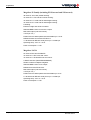
2.2
LAN
Main menu structure
Nearly all LD2 configuration and monitoring is performed using the two-line
LCD in conjunction with the 3-key switch pad and menu system. (Additional
controls are by the two toggle switches mounted on the rear panel.)
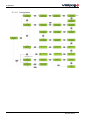
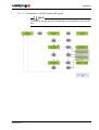
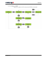
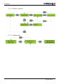
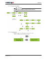
The diagram below shows the top level menu. Menu map diagrams detailing
the complete menu structure are in section section 2.7.1 Menu structure.
NOTE
Repeatedly pressing the *Page* key, from anywhere within the menu structure, will return the user to the main menu.
LD2 Operations manual
AB-V-MA-00512
19(144)
2 Operation
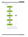
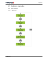
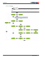
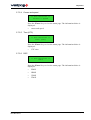
2.2.1
Main menu
Figure 3. LD2 High Level Menu Structure
Press *Page* to step to the required section.
Press the *Enter* key to access the sub-menu.
20(144)
LD2 Operations manual
AB-V-MA-00512
2 Operation
2.3
Operating procedures
2.3.1
Initial start up of LD2
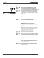
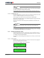
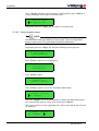
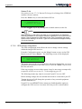
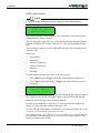
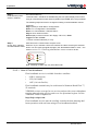
2.3.1.1 Applying power
To power up the LD2 receiver, set the rocker switch (next to the power cable
on the rear panel) to ON ("I") position. The red DC supply LED on the front
panel and the LCD will both illuminate.
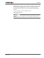
For the first few seconds after power up the LCD display will display the
following (this can take up to 30 seconds):
█ █ █ █ █ █ █ █ █ █ █ █
Veripos
LD2S
SubSea7 - 2008
**** Main Menu ****
Configuration
NOTE
The first two screens will vary according to the LD2 variant in use.
The “Main Menu / Configuration” screen is the entry point for the unit’s
menu system.
2.3.1.2 Checking unit status
After applying power, allow several minutes for the unit to acquire lock on
any available GPS, L-band and HF/MF signals.
The front panel indicators should then be inspected to check the unit status:
DC Supply
HF Lock
Sync
ID
GPS
Message
DGPS
Page
Toggle
DC Supply
Enter
Sync
LD2 integrated positioning mobile
HF Lock
ID
GPS
Message
DGPS
Contrast
Keyboard
Mouse
Figure 4. Status LED’s
LD2 Operations manual
AB-V-MA-00512
21(144)
2 Operation
2.3.1.3 Expected indications for a healthy system
The DC supply indicator must be illuminated. This confirms that an AC
•
supply is connected and that the DC power supply is operational.
•
The Sync indicator must be illuminated. This confirms that the L-band
card is locked onto the downlink beam from a communications satellite
(receiving VERIPOS corrections.)
•
The ID indicator must be steadily illuminated. This confirms that the
unit is enabled (the indicator flashes when the system is disabled).
•
The Message indicator will normally be extinguished. It is only illuminated if a message has been received from the VERIPOS Helpdesk.
•
The GPS indicator should normally be illuminated. This confirms that
the unit is receiving good GPS signals.
NOTE
This indicator reports the satellite status from a GGA telegram which the unit
normally outputs through port P1. Flashing indicates the number of satellites
used in the position computation.
This telegram is present when using the default unit configuration but may
be disabled if certain optional configuration settings are applied. It is therefore possible for the indicator to be extinguished even when good GPS
signals are present.
•
The DGPS indicator should normally be illuminated. This confirms that
the unit is receiving good RTCM corrections.
NOTE
This indicator reports the position correction status from a GGA telegram
which the unit normally outputs through port P1.
This telegram is present when using the default unit configuration but may
be disabled if certain optional configuration settings are applied. It is therefore possible for the indicator to be extinguished even when good corrections are available.
•
The HF/MF Lock indicator should be illuminated if the unit is configured to receive HF/MF corrections and the vessel is in a location where
adequate signals are available.
NOTE
On early units this indicator is labelled “IF Lock”. It is illuminated when using
a 70 MHz antenna system and signal lock is detected in the internal upconverter.
22(144)
LD2 Operations manual
AB-V-MA-00512
2 Operation
If the indicators are as specified above then the antennas, cables and major
components of the LD2 are all operational. If the unit has previously been
configured for its current installation and geographical location, then it
should be fully operational.
NOTE
If the installation has changed or the vessel has moved to a new work area
then reconfiguration may be required even if indicators are normal.
2.3.1.4 Corrective actions if indicators are not as specified
•
DC supply indicator extinguished.
•
No output voltage from internal supply unit – see the “Troubleshooting”
chapter.
Sync indicator extinguished.
•
The L-band card is not locked onto the downlink beam – check demodulator status as detailed in a later section.
ID indicator flashing.
•
The unit is disabled – enable the unit as detailed in a later section.
ID indicator extinguished.
If the unit is an LD2S, the indicator will be extinguished when the
power is switched on. It will not be illuminated until the unit locks to an
L-band signal and the Sync indicator is illuminated (see comments
above concerning Sync).
•
If ID is still extinguished when Sync is illuminated, or if the unit is an
LD2, then there is probably an internal fault. Please call the VERIPOS
Helpdesk and report the problem.
HF/MF Lock indicator extinguished.
•
Not receiving HF/MF signals – see the “Troubleshooting” chapter.
GPS indicator extinguished.
GPS reception problem or non-standard system configuration – check
GPS status as detailed in a later section.
NOTE
If GPS status indicates good satellite reception then the indicator may be
ignored, it is probably inactive because no GGA or GGX output string is
configured on port P1.
LD2 Operations manual
AB-V-MA-00512
23(144)
2 Operation
•
DGPS indicator extinguished.
GPS reception problem, no corrections or non-standard system configuration (where the GPS indicator is extinguished the DGPS indicator will
also be extinguished).
NOTE
Where GPS indicator is flashing then the position output on port P1 is uncorrected. Either the unit is receiving no corrections or stations require enabling
on port P2 – consult VERIPOS Helpdesk.
2.3.2
Enabling and disabling the LD2
NOTE
The VERIPOS Helpdesk can only issue enable codes if a service access
license (SAL) exists and the license number can be determined. Licenses
must be pre-arranged between the user’s company and the VERIPOS
Operations department.
VERIPOS correction signals are provided as a chargeable service. Depending upon the contract between VERIPOS and the user’s company, charges
may be waived during periods when the equipment is not in use. If this is the
case, the user may wish to disable the LD2 during periods of prolonged inactivity.
If the unit has been disabled, the user must re-enable it for the required services before resuming operations.
NOTE
An LD2S unit can only be enabled or disabled if it is receiving L-band
signals from a geo-stationary satellite (the “Access Code” screen may be
blank). The ID indicator will be extinguished when the unit is first switched
on. It will not be illuminated until the unit has locked to the L-band signal
(Sync indicator illuminated).
The user must ensure that the Sync indicator is illuminated before attempting to enter enable or disable codes (see the “Troubleshooting” chapter).
LD2 units can be enabled or disabled without any L-band signal.
2.3.2.1 Checking current status
The current unit status can be determined from the ID indicator on the front
panel.
24(144)
ID LED is on and solid
LD2 variant is enabled
ID LED is flashing
LD2 variant is disabled.
LD2 Operations manual
AB-V-MA-00512
2 Operation
NOTE
LD2S variants – The ID LED may be off until the unit has sync, i.e. is receiving L-band signals.
2.3.2.2 Determine current access code
To enable (or disable) the unit, the user requests an over air enable from
the VERIPOS Helpdesk, so THE FOLLOWING PROCESS IS NOT USED.
In order to generate an enable or disable code, the VERIPOS Helpdesk
require the current access code of the unit. This is found as follows.
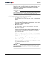
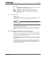
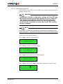
Repeatedly press *Page* until the screen displays:
**** Main Menu ****
Access Code
Press *Enter*. The screen will now display:
*Subsea7 AccessCode*
A08010003D 2A34 66A4
The first 10 characters comprise the access code which must be passed to
the VERIPOS Helpdesk.
In the example screen above, the code is A08010003D:
•
•
•
•
•
•
The first character A is a code for the VERIPOS service(s) use
0801 is the serial number of the LD2 unit
0003 shows the number of times the unit has been enabled/disabled
D indicates that the LD2 is currently disabled (E would indicate
enabled)
2A34 (the second block of characters) indicates the area where the
enable/disable code must be entered
66A4 (the last block of characters) is the confirmation code. This
changes each time the signal activation is changed.
NOTE
It is important the user correctly reports the case (upper or lower) of the first
letter when reporting the access code to the VERIPOS Helpdesk.
Example: Axxxxxxxxx = upper case A
LD2 Operations manual
AB-V-MA-00512
axxxxxxxxx = lower case a
25(144)
2 Operation
2.3.2.3 Request an enable or disable code
Requests for enable/disable codes should be made using the signal notification form (SNF). This should be submitted by email to the VERIPOS
Helpdesk (see the “Contact information” chapter).
NOTE
The current version of the form can be downloaded from the VERIPOS online support web site: http://help.veripos.com
Enable requests can also be submitted by telephone to the VERIPOS Helpdesk (see “Contact information” chapter for current phone numbers).
Before calling Veripos please refer to a signal notification form to ensure that all the
required information is available.
VERIPOS provide a range of services which are available in various combinations. When requesting an enable code the user must specify which services are required.
The full listing of services is provided on the SNF.
The choice of services affects both pricing and system accuracy.
NOTE
Some services are only available on units with specific hardware installed.
2.3.2.4 Enabling the unit
Please refer to instructions on the SNF.
Once VERIPOS receive the SNF form containing the current code and service requirements, the Helpdesk now ENABLE THE LD2 OVER THE AIR so the
example below NO LONGER APPLIES. Skip on to Section 2.3.3.
Enter this code into the screen using the *Toggle* and *Enter* keys.
*Subsea7 AccessCode*
A08010004E 729C 42FF
The confirmation code will change automatically when the access code is
entered.
The new confirmation code (42FF in the example) must now be reported
back to the VERIPOS Helpdesk. This is needed to ensure that the unit has
been successfully activated.
As confirmation, the ID LED on the front panel will change from a flashing
to a solid light indicating the LD2 is enabled for use.
26(144)
LD2 Operations manual
AB-V-MA-00512
2 Operation
NOTE
After enabling the LD2 for the “Verify DP” service, the LD2 must be rebooted
in order to activate the external monitor screen.
Turn the power off for one minute using the switch on the rear of the unit.
2.3.2.5 Disabling the unit
The LD2 is disabled in exactly the same way, obtaining a 4-digit access code
from the VERIPOS Helpdesk and entering it into the unit.
In the example screen above the new access code is A08010004E.
Report the actual code shown to the VERIPOS Helpdesk using the SNF and
they will issue a disable code.
Enter this code into the LD2 and report the confirmation code back to the
Helpdesk.
NOTE
Always report the confirmation code to ensure the correct charges are
applied.
As confirmation the ID LED on the front panel will change from a solid light
to a flashing light indicating the LD2 is disabled.
2.3.3
Checking demodulator status
In order for the LD2 to provide a differential position and RTCM outputs, it
must be locked to the correct communications satellite (referred to as “beam”
or “channel”) for the current location.
For guidance on determining and selecting the correct beam, see the relevant
section.
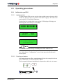
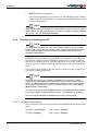
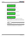
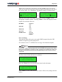
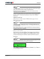
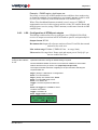
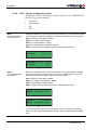
2.3.3.1 Check status
This procedure checks which beam is selected. It also shows the strength of
the received signal and the lock status.
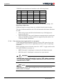
Repeatedly press *Page* until screen displays:
**** Main Menu ****
Status
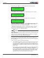
Press *Enter* and screen will display:
*** Status ***
Demodulator
LD2 Operations manual
AB-V-MA-00512
27(144)
2 Operation
Press *Enter*, followed by *Page* to show:
** Demodulator **
Signal Status
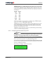
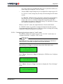
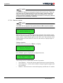
Press *Enter* to access the “Signal Status” page:
This display is for an LD2 unit, see below for LD2S display:
98WEST
3.5V
E-7
-000610Hz ID:R
This display is for an LD2S unit, see above for LD2 display:
98WEST
39.0dB-Hz
-000610Hz ID:V
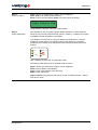
The displays show the following information:
1.
The text at the left of the top line (98WEST) shows the name of the
selected beam (satellite). The possible options are:
AORE, AORW, POR, IOR, 25E, 143.5E and 98W.
2.
The remainder of the top line shows the signal quality.
a. The LD2 displays a signal voltage (3.5V) and the BER (E-7).
Possible signal voltages are: 0.0 V to 3.5 V.
Acceptable values are: 2.0 V to 3.5 V.
Possible BER (bit error rate) values are: E-0 to E-7.
Acceptable values are: E-5 to E-7.
Note: It is important to monitor the BER values. It is sometimes
possible to have high signal strength but a poor BER.
b. The LD2S displays signal strength in the typical range 38-47dB/Hz.
28(144)
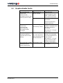
3.
The left of the bottom line shows the lock status (). For correct
operation, all four diamonds must be displayed (see table below for possible displays and their meanings).
4.
The centre of the lower line shows the frequency offset (-000610Hz).
This will typically show values in the range ±3000 Hz.
5.
The right of the lower line shows the service ID (ID:R or ID:V). For
correct operation this is ID:R for an LD2 and ID:V for an LD2S.
LD2 Operations manual
AB-V-MA-00512
2 Operation
Lock status
Reference lock – indicates that the internal synthesiser is locked and is
independent of the received satellite signal.
Symbol lock – indicates that symbol lock has been acquired.
Carrier lock – indicates that carrier lock has been acquired.
Frame synchronisation – indicates that frame synchronisation has
been acquired.
2.3.3.2 Corrective action
Change beam
If the beam shown in the status is not correct for the current location, it must
be changed. See section 2.3.11 Reconfiguring for a new location.
NOTE
If the beam setting is incorrect then it is likely that other settings will also
require re-configuration.
Investigate L-band input problem
If the status display shows that the correct satellite is selected, then there
must be a problem with the L-band input signal. See the “Troubleshooting”
chapter.
2.3.4
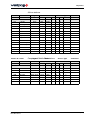
Configuring LD2 demodulator to receive corrections
VERIPOS corrections are broadcast from different geostationary satellites.
The LD2 uses corrections broadcast from one of these satellites. The choice
of satellite is determined by the location of the work area. This is referred to
as “Beam selection” or “Channel selection”.
The beam footprint chosen for use must cover the work area. A chart showing VERIPOS beam coverage is given in section section Figure 10. Global
coverage chart.
Vessels may have more than one LD2 system installed. In most instances
more than one beam with acceptable elevation will be available in the work
area. For best system redundancy the LD2 systems should normally be
configured on different beams.
LD2 Operations manual
AB-V-MA-00512
29(144)
2 Operation
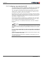
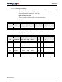
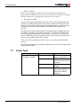
VERIPOS correction data are broadcast on the following beams:
Satellite ULTRA ID
APEX ID
Status
Power
98W
68
81
Operational
High power
AORW
68
81
Operational
High power
25E
68
81
Operational
High power
AORE
68
81
Operational
High power
IOR
68
81
Operational
High power
143.5E
68
81
Operational
High power
POR
68
81
Operational
High power
The above information is updated periodically. For the latest listing, visit:
http://help.veripos.com
Global and region coverage charts are available from the same location.
The type of antenna attached to the LD2 will determine the beams which can
be used:
•
•
When using a spot omni-directional antenna any of the high power
beams can be used.
When interfacing to the vessel’s Inmarsat communications system beam
choice is limited to satellites which are supported by this system. See
VOSS for further information.
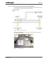
2.3.4.1 Set antenna power toggle switch on rear panel
A spot omni-directional antenna requires a source of DC power for its low
noise amplifiers (LNA). This is supplied by the LD2, via the L-band input
connector.
Before applying power to the unit, ensure the “ANT.V” toggle switch on the
rear panel (if fitted) is correctly set:
•
•
OFF if the unit's L-band input is connected to the Inmarsat system
ON if the unit's L-band input is connected to a spot antenna.
WARNING
Damage may occur if the switch is set to “ON” when connected
to an Inmarsat system. The spot antenna will not function if the
switch is set to “OFF”.
NOTE
Toggle switches must be pulled slightly away from the panel before the
switch position is changed.
30(144)
LD2 Operations manual
AB-V-MA-00512
2 Operation
NOTE
If using an LD2S there is a menu function under “Configuration / Demodulator” which is used to set the “Antenna Power” ON or OFF. This is explained
in section section 2.3.4.4 Check sync indicator.
When the toggle switch is set to OFF it over-rides the LD2S menu selection.
2.3.4.2 Antenna power menu
For LD2S units only there is a menu item to set the antenna power OFF or
ON.
Antenna power should be turned ON when using an omni-directional spot
antenna.
The following steps show how to change this setting in software.
After selecting the channel press *Page* to return to the “Channel Select”
menu:
** Demodulator **
Channel Select
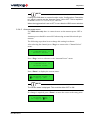
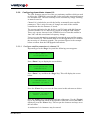
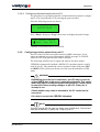
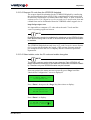
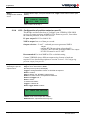
Press *Page* twice to advance to the “Antenna Power” menu:
** Demodulator **
Antenna Power
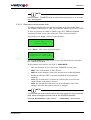
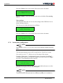
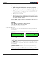
Press *Enter* to display the current status:
* Antenna Power *
█DC Supply: OFF
NOTE
The current status is displayed. This could be either OFF or ON.
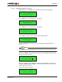
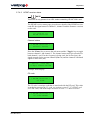
If a change is required, press *Enter* to move the cursor to the entry point:
* Antenna Power *
DC Supply: █OFF
LD2 Operations manual
AB-V-MA-00512
31(144)
2 Operation
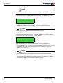
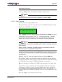
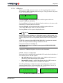
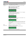
Press *Toggle* until the required setting is displayed then press *Enter* to
accept the change and return to the status menu:
* Antenna Power *
█DC Supply: ON
Repeatedly press the *Page* key to return to the main menu.
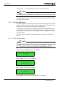
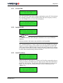
2.3.4.3 Select downlink beam
NOTE
LD2 and LD2S units have different L-band cards. There are slight differences in their menus.The guide below details the differences.
Repeatedly press the *Page* key until the following screen appears:
**** Main Menu ****
Configuration
Press *Enter* and the screen changes to:
*** Configuration ***
Demodulator
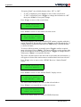
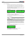
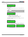
Press *Enter* again:
** Demodulator **
Channel Select
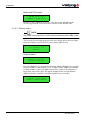
Press *Enter* again to access the downlink channel table:
* Channel Select *
█01. AOR(E)
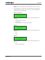
Press the *Toggle* key to step through the available downlink beams until
the required beam appears on the screen, then press *Enter*.
The cursor will move to the right hand side of the screen and the letter N will
be displayed:
* Channel Select *
07. 98WEST
█N
32(144)
LD2 Operations manual
AB-V-MA-00512
2 Operation
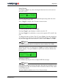
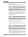
Press *Toggle* to change the N to a Y, then press *Enter* to confirm the
change. The screen will now display:
* Channel Select *
>07. 98WEST
The chevron “>” indicates that the beam now is selected.
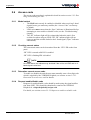
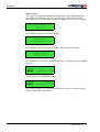
2.3.4.4 Check sync indicator
After a short delay whilst the L-band card acquires lock, the Sync indicator
should illuminate to confirm that the LD2 is receiving the selected beam.
Sync
HF/MF Lock
ID
GPS
Message
DGPS
Figure 5. Status LED’s
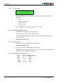
2.3.4.5 Check demodulator status
After changing the beam it is advisable to check the received signal level.
2.3.4.6 Check available reference stations
After confirming that the signal level is satisfactory, check the list of reference stations which are available from the selected beam. This will confirm
the correct operation of the unit and verify that the user has selected the
correct beam. See the following section for details on how to do this.
2.3.5
Available reference stations
NOTE
It may take up to 10 minutes for the unit to accumulate a full station list after
selecting a new beam. (Station data is not available until a Type 3 message
has been received.)
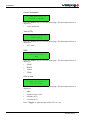
Check the available reference stations as follows.
Repeatedly press the *Page* key until the following screen appears:
**** Main Menu ****
Configuration
LD2 Operations manual
AB-V-MA-00512
33(144)
2 Operation
Press *Enter* and the screen changes to:
*** Configuration ***
Demodulator
Press *Enter* and the screen changes to:
** Demodulator **
Channel Select
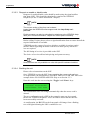
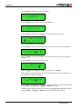
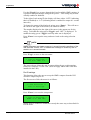
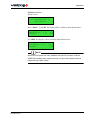
Repeatedly press *Page* until the screen changes to:
** Demodulator **
Station ID List
Press *Enter* and the screen changes to something like:
* Station ID List *
Aberdeen 0777
This screen displays the name of a station and its station ID number.
Pressing the *Toggle* key will cycle through a list of all available stations.
The user should verify that the list includes the stations relevant to the work
area.
NOTE
Ultra corrections have a “station name” of “Veripos” and “00” as the first two
characters of the ID.
A fully populated list including local stations, confirms that the appropriate
beam has been selected and that the unit is receiving RTCM data.
34(144)
LD2 Operations manual
AB-V-MA-00512
2 Operation
2.3.6
Configuring demodulator channel 16
The LD2 firmware stores a list of the geo-stationary satellites which are used
to deliver the VERIPOS correction data. It also stores the associated frequencies and data rates. The user normally selects a satellite by simply selecting
its name from a list.
Channel 16 is included to provide the facility to manually enter satellite
parameters. This is only necessary if changes are made to the satellite
constellation after the firmware is issued.
The current application for this facility is on LD2 units with old firmware
versions (decoder ver 4.1 and below), which are using the IOR satellite.
There was a power increase in the VERIPOS service from this satellite in
June 2007 and this necessitated a frequency change.
Users were sent instructions on manually entering the new satellite parameters into channel 16. This enabled them to use the upgraded service without
the necessity of a firmware upgrade. The specimen figures in the example
below are taken from the IOR upgrade instructions.
2.3.6.1 Configure satellite parameters in channel 16
Repeatedly press the *Page* key until the following screen appears:
**** Main Menu ****
Configuration
Press *Enter* key to display the screen below:
*** Configuration ***
Demodulator
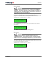
Press *Enter* key and then the *Page* key. This will display the screen
below:
** Demodulator **
Channel 16 Edit
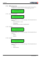
Press the *Enter* key to access the first screen in this sub-menu as below:
* Channel 16 Edit *
Name: Unknown
Press the *Enter* key to highlight first letter of the name. Use the *Toggle*
key to step through the letters of the alphabet. When the correct character is
displayed, press the *Enter* key. This accepts the character and steps on to
the next letter.
A maximum of six characters may be entered.
LD2 Operations manual
AB-V-MA-00512
35(144)
2 Operation
NOTE
e.g.for the June 2007 update we changed the name to “HP IOR”
After the sixth letter, or blank, has been set, press the *Enter* key. The
display moves on to the “Frequency selection” display shown below:
* Channel 16 Edit *
Freq: 1535070000Hz
Press the *Enter* key again and the first number is highlighted. Use the
*Toggle* and *Enter* keys as before to set the required frequency.
NOTE
For the June 2007 update, use the value shown above.
After the last number has been set, press the *Enter* key and the display
moves on to the “Data rate display” shown below:
* Channel 16 Edit *
Data Rate: 1200bps
Press the *Enter* key again and the data rate 1200 is highlighted.
Use the *Toggle* key, if required, to step through the options which are 600,
1200, 2400, and 4800. Once the required value is displayed, press the
*Enter* key to accept it.
NOTE
For the example June 2007 update we used the value shown above.
This completes the configuration of the parameters in Channel 16. Repeatedly press the *Page* key to return to the main menu.
36(144)
LD2 Operations manual
AB-V-MA-00512
2 Operation
2.3.6.2 Selecting channel 16 for use
Repeatedly press the *Page* key until the screen below is displayed:
**** Main Menu ****
Configuration
Press *Enter* key to display the screen below:
*** Configuration ***
Demodulator
Press *Enter* key to display the screen below:
** Demodulator **
Channel Select
Press *Enter* again to access the downlink channel table:
* Channel Select *
01.AOR(E)
Press the *Toggle* key 15 times to step through the downlink beams to
channel 16.
NOTE
The channel 16 name displayed will be that previously entered by the user.
Next press *Enter*. This will move the cursor to the right hand side of the
screen next to the letter N:
* Channel Select *
16.
HP IOR █N
Press the *Toggle* key to change the character from an N to a Y then confirm the entry by pressing *Enter*. This will select channel 16 as the beam
delivering the corrections.
The screen will now display:
* Channel Select *
>16.
HP IOR
LD2 Operations manual
AB-V-MA-00512
37(144)
2 Operation
The chevron “>” symbol indicates that this is the selected beam.
NOTE
The channel 16 name displayed will be that previously entered by the user.
It is good practice after selecting a channel to check the demodulator status.
See the relevant section.
2.3.7
Checking GPS status
The GPS indicator on the front panel reports the satellite status from a GGA
telegram which the unit normally outputs through port P1. Flashing indicates
the number of satellites used in the position computation.
This telegram is present when using the default unit configuration but may
be disabled if certain optional configuration settings are applied. It is therefore possible for the indicator to be extinguished even when good GPS signals are present.
The GPS status may still be checked using the menu system, as detailed
below.
2.3.7.1 GPS Receiver Menu
NOTE
The “Status/GPS Receiver” sub-menus are only accessible when port P5 is
switched to OFF. If none of the sub-menus are available, see section section
2.3.7.2 Reconfiguring port P5 for instructions for configuring port P5.
Repeatedly press *Page* until screen displays:
**** Main Menu ****
Status
Press *Enter* and screen will display:
*** Status ***
Demodulator
Press *Page* and screen will display:
*** Status ***
GPS Receiver
Press *Enter* to move to the “GPS Receiver” sub-menus.
38(144)
LD2 Operations manual
AB-V-MA-00512
2 Operation
Repeatedly pressing *Page* will cycle through the sub-menus, as listed
below.
Pressing *Enter* in any sub-menu will display the associated parameters.
Checking “Position”, “DOPs” and “SV’s in view” should be sufficient to
confirm correct receiver operation.
Receiver information
** GPS Receiver **
Receiver Info
Press the *Enter* key to view the status page. The information below is
displayed:
•
•
•
model and firmware version
serial number
installed options (not currently implemented).
Position
** GPS Receiver **
Position
Press the *Enter* key to view the status page. The information below is
displayed:
•
•
Lat
Long.
Altitude
** GPS Receiver **
Altitude
Press the *Enter* key to view the status page. The information below is
displayed:
•
•
LD2 Operations manual
AB-V-MA-00512
Alt
V. Vel (vertical velocity).
39(144)
2 Operation
Course and speed
** GPS Receiver **
Course & Speed
Press the *Enter* key to view the status page. The information below is
displayed:
•
course and speed.
Time (UTC)
** GPS Receiver **
Time (UTC)
Press the *Enter* key to view the status page. The information below is
displayed:
•
UTC time.
DOP
** GPS Receiver **
DOP
Press the *Enter* key to view the status page. The information below is
displayed:
•
•
•
•
PDOP
HDOP
VDOP
TDOP.
SV’s in view
** GPS Receiver **
SVs in View
Press the *Enter* key to view the status page. The information below is
displayed:
•
•
•
•
PRN
signal to noise (S/N)
azimuth (A/Z)
elevation (EL).
Press *Toggle* to page through all the SV's in view.
40(144)
LD2 Operations manual
AB-V-MA-00512
2 Operation
2.3.7.2 Reconfiguring port P5
Port P5 must be set to OFF before the GPS receiver status information can be
displayed on the LD2.
WARNING
Depending on system configuration, setting port P5 to OFF may
disrupt the operation of external equipment such as Verify QC.
This change should NOT be made during vessel operations
whilst the external equipment is in use. The original setting
should also be re-instated once the status of the GPS receiver
has been checked.
NOTE
If Verify QC is installed and operational, it will display any necessary GPS
status information – it should not be necessary to use the LD2 status menu.
Port P5 may be disabled as follows.
Press *Page* until the screen displays:
**** Main Menu ****
Configuration
Press *Enter* and the screen will display:
*** Configuration ***
Demodulator
Press *Page* twice and the screen will change to:
*** Configuration ***
Serial Ports
Press *Enter*, then press *Page* four times to display the port P5 setup:
P5: GPS I/O █REMOTE
>GPS Menus disabled<
LD2 Operations manual
AB-V-MA-00512
41(144)
2 Operation
Press *Toggle* to change the port P5 output to:
P5: GPS I/O █OFF
Press *Enter* to disable the output.
NOTE
The same procedure may be used to set the port back to "REMOTE" when
the status checks are completed.
2.3.8
Configuring RTCM output ports
RTCM data is output from the LD2 on ports P2 and P4. The data string
configured on port P2 is also used internally when computing positions for
output on port P1.
All stations available in the demodulator station list (see above) are potentially available for output. However the output port configuration makes
provision for each reference station to be individually enabled or disabled.
VERIPOS recommend that all available reference stations are initially
enabled on both P2 and P4. Users should subsequently tailor their configuration to match their specific requirements.
NOTE
The final selection of reference stations must be made by reference to the
system receiving the corrections. The full station list will contain stations
which are too far from the work area to provide usable corrections (VERIPOS recommend a maximum range of 2500 Km).
•
•
•
If the external system has sufficient intelligence (as with Verify QC), it
will automatically exclude distant stations and weight the data from the
remaining stations according to range and other factors.
If the external system has less intelligence, the user should enable the
closest stations and disable the remainder.
In the extreme case, some GPS receivers can accept RTCM corrections
but cannot differentiate between stations. (i.e. they have no multi-reference capability).
For these receivers, only a single reference station should be enabled.
(Enabling multiple stations will generate position noise since the
receiver will compute fixes, in turn, from each individual reference
station.)
42(144)
LD2 Operations manual
AB-V-MA-00512
2 Operation
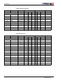
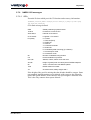
VERIPOS Ultra has no range limitations and may be used in any location.
The corrections are in a VERIPOS proprietary format however, and can only
be decoded by VERIPOS systems. When the LD2 is enabled for Ultra service the user should always enable the Ultra ID on the output port connected
to Verify QC.
Satellite
Ultra ID
POR
0068
143.5E
0068
IOR
0068
25E
0068
AORE
0068
AORW
0068
98W
0068
Global and regional coverage charts are available on the VERIPOS online
support site (VOSS) at: http://help.veripos.com
VERIPOS also provide “Verichart” software which enables the user to generate a chart showing the best beams and reference stations for the exact
location of the worksite. This software is provided with new systems and
may also be downloaded from VOSS.
VERIPOS recommend that this software is installed during commissioning
so that it is available during operations.
2.3.8.1 Configuring reference stations on port P2
NOTE
By default both P2 and P4 are configured to output RTCM at a baud rate of
9600 baud. It is recommended that the user leaves these settings
unchanged. The displays will then be as shown in the following illustrations.
These only show the procedure for enabling/disabling stations.
If connecting to an external system which requires different settings for baud
rate etc., the user should refer to the more detailed explanation in the manual.
Port P2 is configured as follows.
Repeatedly press *Page* until the screen shows:
**** Main Menu ****
Configuration
LD2 Operations manual
AB-V-MA-00512
43(144)
2 Operation
Press *Enter* and the screen will display:
*** Configuration ***
Demodulator
Press *Page* twice and the screen will change to:
*** Configuration ***
Serial Ports
Press *Enter* followed by *Page* to display the port P2 setup:
P2: RTCM(P) DNLINK
█ 9600 STN: 505 N
The cursor defaults to the baud rate.
Press *Enter* twice to move the cursor to the reference station ID number:
P2: RTCM(P) DNLINK
9600 STN:█505 N
Press *Toggle* to move through the list to the desired reference station ID
number.
Press *Enter* to move the cursor across:
P2: RTCM(P) DNLINK
9600 STN: 501█N
Press *Toggle* to change the N to a Y followed by *Enter*.
The reference station will now be selected and the cursor will jump back to
the reference station ID number:
P2: RTCM(P) DNLINK
9600 STN:█501 Y
Use *Toggle* again to move through the list until the next desired station ID
is displayed. Use *Enter*, *Toggle*, *Enter* to select.
Stations can be deselected in the same way by toggling through the list and
using *Enter*, *Toggle*, *Enter* to deselect the desired station.
44(144)
LD2 Operations manual
AB-V-MA-00512
2 Operation
2.3.8.2 Configuring reference stations on port P4
The procedure for configuring port P4 is almost identical to that for configuring P2. The only difference is in selecting the port to modify.
From the following screen (see above):
*** Configuration ***
Serial Ports
Press *Enter* then press *Page* three times to display the port P4 setup:
P4: RTCM(P) DNLINK
█ 9600 STN: 505 N
Continue as described (above) for port P2.
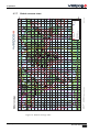
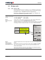
2.3.9
Configuring position output from port P1
Port P1 on the LD2 has two output modes for NMEA messages: Local,
where the onboard processor generates the NMEA message, or GPS RX,
where the GPS card generates the NMEA message.
The following describes how to apply and when to use these modes.
VERIPOS recommend by default a NMEA GGA position output is configured on port P1. This enables the correct operation of the front panel GPS
and DGPS LED’s which provide the user with a useful indication of GPS
status.
WARNING
Depending upon the local installation, port P1 may be used to
output NMEA data to the user's external equipment. This equipment may require a different output configuration. Caution must
be exercised when making changes to port P1 if the port is
already in use.
Check whether any cable is attached to the P1 socket on the
rear panel.
If in doubt, consult the VERIPOS Helpdesk.
NOTE
This port outputs RS-232 data at a default rate of 9600 baud. The format is
fixed with 8 data bits, no parity and 1 stop bit (8-N-1).
LD2 Operations manual
AB-V-MA-00512
45(144)
2 Operation
Repeatedly press *Page* to reach the entry point of the main menu:
**** Main Menu ****
Configuration
Press *Enter* then press *Page* twice. The following screen is shown:
*** Configuration ***
Serial Ports
Press the *Enter* key to select the first page which is serial port P1:
P1: NMEA OUT GPS RX
This screen is used to select the source of the NMEA output message. The
options are “GPS RX” or “LOCAL”. Press *Toggle* until the required
option is displayed then press *Enter* to select it.
VERIPOS recommend using “LOCAL” as the default setting. “GPS RX”
may be used if demanded by the survey specification (see notes below).
Further advice from the VERIPOS Helpdesk.
NOTE
When “GPS RX” is selected the NMEA position data is computed within the
GPS receiver itself.
Where “LOCAL” is selected the NMEA position is computed in a separate
processor within the LD2 using VERIPOS algorithms.
In both cases, the computation uses the RTCM corrections configured on
port P2. These corrections are derived from the stations enabled during port
P2 configuration.
Using “LOCAL” offers the following advantages:
•
The VERIPOS algorithms compute a position based on the closest reference stations enabled on port P2 (up to four stations are utilised). The
processor therefore computes the optimum position available from the
selected stations, regardless of whether all stations are enabled or just a
single station.
If the position is generated in the GPS receiver, the configuration of port
P2 is constrained by the multi-reference capabilities of the specific
receiver installed. Some receivers specify a maximum number of reference stations; some only permit a single station. In the latter case enabling multiple stations may result in position noise since fixes will be
generated in turn, from each individual reference station.
46(144)
LD2 Operations manual
AB-V-MA-00512
2 Operation
•
P2 is also used as the main RTCM output port so potential conflicts are
much reduced by using the “LOCAL” mode.
Various NMEA output strings may be configured for output on port P1.
In “LOCAL” mode, strings may be easily selected using the LD2 menu
system.
In “GPS RX”, different strings can only be selected by reprogramming
the GPS receiver. This is accomplished by uploading configuration
scripts. The receiver is initially configured to output only the ZDA
string. If the user wishes to change this setting, it is advisable to contact
the VERIPOS Helpdesk for assistance.
When in “LOCAL” mode, the output baud rate is fixed at 9600 baud.
In “GPS RX” mode it is possible to change the baud rate but this requires
reprogramming of the GPS receiver. If the user wishes to change this setting
contact the VERIPOS Helpdesk for assistance.
2.3.9.1 Configuring the strings output in “Local” mode
The NMEA strings to be output on port P1 (in “LOCAL” mode only) are
configured from the “Configure / GPS” menu.
NOTE
This menu structure exists for historical reasons. Despite the allusions to
GPS receiver, it is actually configuring the PC104 processor.
Repeatedly press *Page* to reach the entry point of the main menu:
**** Main Menu ****
Configuration
Press *Enter* followed by *Page* to display the “GPS Receiver Configuration” menu:
*** Configuration ***
GPS Receiver
Press *Enter* then press *Page* four times to display the “Port A Settings”
menu:
** GPS Receiver **
Port A Settings
LD2 Operations manual
AB-V-MA-00512
47(144)
2 Operation
Press *Enter* to access the first screen in the sub-menu which is shown
below:
* Port A Settings *
NMEAO/P: GGA 1.0
Press *Enter* to move the cursor to the centre of the screen (“String selection” mode).
Use the *Toggle* key to move through the list of available NMEA strings
(see table below). It is possible to output multiple strings from port P1. Each
string may be individually enabled or disabled.
To the right of each string ID, the display will show either “OFF” (indicating
that it is disabled) or “1.0” (indicating that it is enabled for output at 1 Hz,
i.e. one set of data every second).
To change the status of the displayed string, press *Enter*. This will move
the cursor to the right of the screen (“Rate selection” mode).
NOTE
For the front panel GPS and DGPS indicators to be activated either a GGA
or a GGX string must be enabled.
The number displayed to the right of the cursor is the output rate for the
string.
To disable the string, press *Toggle* until “OFF” is displayed.
To enable the string, press *Toggle* until any other rate is displayed.
Press *Enter* to accept the entry and move back to the string selection
mode.
NOTE
NMEA messages are always output at one second intervals regardless of
the rate selected. Select “OFF” to disable the message or select any rate to
enable it at one second intervals.
48(144)
LD2 Operations manual
AB-V-MA-00512
2 Operation
Positioning messages
Message
type
Description
GGA
Position fix data which provide 3D location and accuracy data.
GGX
GGA with a position accuracy at seven (7) decimal places.
GLL
Geographic latitude and longitude.
VTG
Velocity made good.
GSA
It includes the numbers of the satellites being used in the current
solution and the DOP.
GSV
Satellites in view shows data about the satellites that the unit might be
able to find based on its viewing mask and almanac data.
RMC
Position, velocity and time data.
ZDA
Date and time.
GRS
GPS range residuals.
GST
GPS pseudorange noise statistics.
These are described in detail in section section 2.7.6 NMEA 0183 messages.
2.3.10 Configure to receive VERIPOS HF corrections
An LD2 can only receive HF signals if the optional HF card is installed. If
any of the menus described in the following text are absent from the user's
LD2, this option is probably not installed. Contact the VERIPOS Helpdesk
for further advice.
VERIPOS currently support HF stations in the North Sea, North America
and South America. See the station listing in section section 2.7.5.8 VERIPOS station listings. Refer also to VERIPOS online support site at:
http://help.veripos.com
This site will be updated with any changes which may occur after publication
of this manual.
These HF stations are maintained by VERIPOS and offer standards of accuracy as for our reference stations. They are chargeable and encrypted to prevent unauthorised access.
In order to use the service the user must first obtain a decryption key to enter
into his unit. This key is referred to as the C3 code. It is different for each
region of operation as is unique for each individual LD2.
The C3 code must be obtained from the VERIPOS Helpdesk. In order to
compute a code to match the specific unit, the user must supply the internal
code (C2 code) for that unit.
This can easily be determined using the menu system.
LD2 Operations manual
AB-V-MA-00512
49(144)
2 Operation
The following steps are used to bring the unit into service:
•
•
•
•
•
•
determine the C2 code for each LD2
submit a request for a C3 code to the VERIPOS Helpdesk
select the appropriate HF station from the list displayed by the unit
enter the C3 code
enable decryption
check the signal status.
2.3.10.1 Determine the unit’s C2 code
From any point in the menu structure, repeatedly press *Page* until the
“Main menu Status” screen is displayed:
**** Main Menu ****
Status
Press *Enter* then press the *Page* key twice to display:
*** Status ***
HF/MF Receiver
Press *Enter* then *Page* to display:
** HF/MF Receiver **
C2 Code
Press *Enter* to display:
* HF/MF Receiver *
C2 Code: XXXXX
The five-digit number on the right of the bottom row is the unit C2 code
which must be reported to the VERIPOS Helpdesk.
50(144)
LD2 Operations manual
AB-V-MA-00512
2 Operation
2.3.10.2 Request C3 code from the VERIPOS Helpdesk
The request should be submitted to the VERIPOS Helpdesk by email using
the signal notification form (SNF). Fully completing this form ensures that
all necessary information is available and avoids delays. A form is shown in
section section 2.10.2 Signal access licence and service notification form and
a blank form can be downloaded from the VERIPOS online support site at:
http://help.veripos.com
It is impossible to compute a C3 code unless the unit C2 code and the
vessel’s operating region are known.
NOTE
Enable requests can also be submitted by telephone to the VERIPOS Helpdesk. Before calling refer to a SNF to ensure that all the required information
is available.
The VERIPOS Helpdesk can only issue a C3 code if a service access license
(SAL) exists which includes the supply of HF services. Licenses must be
pre-arranged between the user’s company and the VERIPOS Operations
department.
2.3.10.3 Select station, enter the C3 code and enable decryption
NOTE
The HF/MF card can receive data on two channels. Each VERIPOS HF
station transmits corrections on two different frequencies to enhance reliability. Therefore only one VERIPOS station may be selected.
From any point in the menu structure repeatedly press *Page* until the
“Main menu Configuration” screen is displayed:
**** Main Menu ****
Configuration
Press *Enter* then press the *Page* key three times to display:
*** Configuration ***
HF/MF Receiver
Press *Enter* to display:
** HF/MF Receiver **
Frequency Band: █HF
LD2 Operations manual
AB-V-MA-00512
51(144)
2 Operation
“Frequency Band” may initially display either “HF” or “MF”.
•
•
If “HF” is displayed, press *Page* to move to the screen below.
If “MF” is displayed, press *Toggle* to change the indication to “HF”
then press *Enter* to accept the change.
Press *Page* to move to the screen below:
** HF/MF Receiver **
Station Select
Press *Enter* to move to the station selection screen:
* HF Station Select *
>Den Helder
001
This screen displays a list of the VERIPOS HF stations, together with their
station ID numbers. Repeatedly pressing *Toggle* scrolls through the list. If
a station has previously been selected, it is identified by a chevron bracket
(>) before its name.
To select a different station, repeatedly press *Toggle* until the required
name is displayed. Press *Enter*. The cursor will move to the extreme right
of the screen and an N will be displayed. Press *Toggle* to change this to a
Y then press *Enter* to accept the selection.
The cursor will move back to the left of the screen and a chevron bracket (>)
will appear in front of the station name to confirm that it has been selected.
Press *Page* twice to move to the “HF/MF Receiver / Station Details”
screen:
** HF/MF Receiver **
Station Details
Press *Enter* to move to the “Station Details” display screen:
* Station Details *
Den Helder
001
The station name should be the same as that selected above.
Press *Enter* to accept and move to the next screen:
* Station Details *
Name: Den Helder
Most of the station details are fixed for VERIPOS stations.
52(144)
LD2 Operations manual
AB-V-MA-00512
2 Operation
Press *Toggle* five times to move to the code entry screen:
* Station Details *
C3 Code: ******
Press *Enter* to move the cursor to the first character of the six-digit code.
Repeatedly press *Toggle* until the first character matches the first digit of
the supplied code. Press *Enter* to accept the value and move to the next
digit.
Repeat this procedure until the complete six-digit code has been entered.
After the last entry, the cursor will move back to the left of the screen and the
code will be hidden (replaced by asterisks).
Press *Page* twice to move to the “Decryption” screen:
* Decryption *
█Enabled
When using VERIPOS HF stations, decryption must be enabled.
If necessary, press *Toggle* to display “Enabled” then press *Enter* to
accept.
This completes the entries. Repeatedly press *Page* to return to the main
menu.
2.3.10.4 Check HF status
From any point in the menu structure, repeatedly press *Page* until the
“Main Menu / Status” screen is displayed:
**** Main Menu ****
Status
Press *Enter* then press the *Page* key twice to display:
*** Status ***
HF/MF Receiver
Press *Enter* to display the “HF/MF Receiver / Channel Status” screen:
** HF/MF Receiver **
Channel Status
LD2 Operations manual
AB-V-MA-00512
53(144)
2 Operation
Press *Enter* to access the “Channel Status” screen:
Ch1: 01 1234kHz
123bps 45dBuv/m 67dB
Use *Toggle* to switch between Ch1 and Ch2.
For each channel, the display shows the frequency in use, the bit rate (bps),
the signal strength (dBuv/m) and the calculated signal to noise ratio (db).
2.3.11 Reconfiguring for a new location
After moving to a new geographical region, the following steps must be performed to reconfigure your system:
1.
Each LD2 demodulator must be reconfigured to receive a local communications satellite. This is carried out using the push buttons and the
LCD on the demodulator front panel.
See relevant procedure.
2.
Each LD2 demodulator must be reconfigured to enable the required
reference stations on the relevant output port(s). (This must include the
Ultra “station” if the Ultra service is used.) This is carried out using the
push buttons and LCD on the demodulator front panel.
See relevant procedure
3.
Verify DP software (if installed) does not require reference stations
configuration. It will automatically select the nearest stations (up to four
stations) and use them in its calculation. (The stations must be enabled
in port P2, as indicated above.) Users will still need to reconfigure the
local communications satellite.
NOTE
Where the LD2 is used in conjunction with VERIPOS Verify QC software,
this will also require configuration as follows.
4.
The “RTCM inputs” on each Verify QC system must be reconfigured by
selecting the appropriate “Beam” and “Stations”.
5.
The “Calculations” on each Verify QC system must be reconfigured by
selecting the appropriate “Stations”.
See Verify QC manual for full details.
54(144)
LD2 Operations manual
AB-V-MA-00512
2 Operation
2.3.12 Determining firmware versions
Some features of the LD2 vary according to the versions of firmware which
are installed.
The VERIPOS Helpdesk may ask the user to check which versions are
installed on the system. This may be determined as follows.
From any location in the menu, repeatedly press the *Page*" key until the
display shows:
**** Main Menu ****
Status
Press *Enter*. The display will show:
*** Status ***
Demodulator
Press *Enter*. The display will show:
** Demodulator **
Unit ID
Press *Page* twice. The display will show:
** Demodulator **
S/W Version
Press *Enter*. If the unit is an LD2, the display will be similar to that
shown below:
Demodulator: 1.0 2.1
Decoder:
1.0 4.4
If the unit is an LD2S, the display will be similar to that shown below:
Boot/Main:
Decoder:
1.5
10.2
1.20
Record the version numbers and report them to the VERIPOS Helpdesk.
LD2 Operations manual
AB-V-MA-00512
55(144)
2 Operation
2.3.13 Configuring a 1 pps output from the LD2
The LD2 provides a facility for outputting a 1 pps (pulse per second) signal
to external equipment. This is typically used to provide accurate time synchronisation for third party navigation systems or multi-beam sonar.
The 1 pps signal is derived directly from the internal GPS receiver and is
output on pin 1 of port P1. The exact specification of the signal will vary
according to the model of GPS receiver installed.
Depending upon the options specified when ordering the LD2; the internal
GPS receiver may require an upgrade before it can output 1 pps. If required,
the upgrade is chargeable but may easily be performed in the field since it
only requires a change of firmware.
If the user has suitable test equipment (e.g. oscilloscope), the 1 pps output
may be checked by directly observing the signal on pin 1 of port P1 (there
are no switches or menu settings associated with this output).
In case of difficulty, or for additional information, contact the VERIPOS
Helpdesk.
NOTE
The 1 pps pulse is very narrow and the amplitude may be as low as 2.5 volts
(depends on receiver model) so it may be difficult to observe on an oscilloscope.
Because of these characteristics, it is also very susceptible to degradation if
it is wired using the same cable as the RS-232 output which is also present
on port P1.
VERIPOS strongly advise using a breakout harness and running the 1 pps
signal in a separate coaxial cable.
The harness may be purchased from VERIPOS or fabricated by the user,
using the details below.
56(144)
LD2 Operations manual
AB-V-MA-00512
2 Operation
2.3.13.1 LD2 port P1 cable for outputting 1 pps and NMEA ZDA
This diagram provides the details required to make up a PPS/ZDA cable harness which can be connected to port P1 of the LD2.
Figure 6. LD2 1 pps Splitter Cable
The following photographs are examples of a typical harness constructed
from this circuit diagram.
Figure 7. Y-Cable for LD2
LD2 Operations manual
AB-V-MA-00512
57(144)
2 Operation
Figure 8. Connector for port P1 on LD2
2.4
System test
System test allow the user to check the operation of the front panel LCD.
Access to system test is by pressing the *Page* key in the top level main
menu until “System Test” is displayed. Then press the *Enter* key to show
the following display:
**** Main Menu ****
System Test
Press the *Enter* key to initiate an internal self test. The display changes to
show progress through the test cycle.
2.5
System information
The system information has the following displays: current processor software version, controller software version, GNSS hardware onboard, and the
IP address of the unit.
**** Main Menu ****
System Information
58(144)
LD2 Operations manual
AB-V-MA-00512
2 Operation
2.5.1
PC/104 S/W
*System Information*
PC/104 S/W
The “PC/104 S/W” page gives software information on the PC/104 card and
the controller firmware version number. When the above display is shown,
press the *Enter* Key to access the information.
** PC/104 S/W**
LD2 Controller 5.93
2.5.2
Installed H/W
*System Information*
Installed H/W
NOTE
The user should only make changes if directed to do so by a VERIPOS
engineer.
Incorrect entries in this menu may render the unit inoperable.
The “Installed Hardware” menu is only for use by the VERIPOS workshop
engineer to specify which optional GPS card and which HF card (HF+MF
3001 card or beacon SBX-4 card) is fitted in the unit. Firmware uses entries
to determine which menus should be displayed and what data formats should
be used when communicating with the modules.
2.5.3
Host IP address
*System Information*
Host IP Address
When the LD2 is connected to a network, the IP will be assigned by the network, provided it is a DHCP network, otherwise the LD2 unit will default to
the IP 192.168.150.249. The IP of the LD2 will be displayed in the screen
below, to access this screen when the above screen is shown press the
*Enter* key.
Host IP Address
192.168.123.456
LD2 Operations manual
AB-V-MA-00512
59(144)
2 Operation
2.6
Access code
The access code procedure is explained in detail in section section 2.3.2 Enabling and disabling the LD2.
2.6.1
Model variant
•
The LD2S unit can only be enabled or disabled when receiving L-band
signals from a geo-stationary satellite (the “Access Code” screen may
be blank).
•
LD2S users must ensure that the “Sync” indicator is illuminated before
attempting to enter enable or disable codes (see the “Troubleshooting”
chapter).
•
The “ID” indicator light will be extinguished when the unit is first
switched on when using an LD2S. The “ID” indicator light will not
come on until the unit has locked to the L-band signal (“Sync” indicator
illuminated).
2.6.2
Checking current status
The current unit status can be determined from the “ID” LED on the front
panel.
“ID” LED is on and solid LD2 is enabled
“ID” LED is flashingLD2 is disabled
NOTE
As noted above, the indicator may be blank if the unit is an LD2S and no Lband signal is received.
2.6.3
Determine current access code
To enable (or disable) the unit the user must manually enter a four-digit code
which is supplied by the VERIPOS Helpdesk, see section section 2.3.2.2
Determine current access code for details.
2.6.4
Request enable/disable code
Requests for enable/disable codes should be made using the signal notification form (SNF). This should be submitted by email to the VERIPOS
Helpdesk at: [email protected]
For details, see section section 2.3.2.3 Request an enable or disable code.
60(144)
LD2 Operations manual
AB-V-MA-00512
2 Operation
2.7
Reference information
2.7.1
Menu structure
2.7.1.1 Main menu
LD2 Operations manual
AB-V-MA-00512
61(144)
2 Operation
2.7.1.2 Configuration
62(144)
LD2 Operations manual
AB-V-MA-00512
2 Operation
2.7.1.3 Configuration – Demodulator
LD2 Operations manual
AB-V-MA-00512
63(144)
2 Operation
2.7.1.4 Configuration – GPS
64(144)
LD2 Operations manual
AB-V-MA-00512
2 Operation
2.7.1.5 Configuration – Serial port
LD2 Operations manual
AB-V-MA-00512
65(144)
2 Operation
2.7.1.6 HF setup
NOTE
This menu is only present if the relevant HF card is installed in the LD2 variant.
66(144)
LD2 Operations manual
AB-V-MA-00512
2 Operation
2.7.1.7 Configuration – HF/MF receiver (MF setup)
NOTE
This menu is only present if the relevant MF card is installed in the LD2 Variant.
LD2 Operations manual
AB-V-MA-00512
67(144)
2 Operation
2.7.1.8 Configuration – Beacon receiver
NOTE
This menu is only present if the relevant MF card for IALA is installed in the
LD2 Variant.
68(144)
LD2 Operations manual
AB-V-MA-00512
2 Operation
2.7.1.9 Status
2.7.1.10 Status – Demodulator
LD2 Operations manual
AB-V-MA-00512
69(144)
2 Operation
2.7.1.11 Status – GPS
70(144)
LD2 Operations manual
AB-V-MA-00512
2 Operation
2.7.1.12 Status – HF/MF
Menus are available for LD2 variant where HF/MF card installed.
LD2 Operations manual
AB-V-MA-00512
71(144)
2 Operation
2.7.1.13 Status – Beacon
2.7.1.14 System test
72(144)
LD2 Operations manual
AB-V-MA-00512
2 Operation
2.7.1.15 System information
WARNING
Do NOT make changes to entries in these menus.
2.7.1.16 Access code
Refer to section 2.3.2.2 Determine current access code
127(29(5WKH$,5HQDEOLQJQRZXVHG.
LD2 Operations manual
AB-V-MA-00512
73(144)
2 Operation
2.7.2
Configuration mode
The configuration menu allows the user to setup the different components of
the LD2: Demodulator, GNSS receiver, Serial ports and HF/MF receiver.
The menu maps are detailed in .
To access the Configuration menu, press the *Page* key until Configuration
is shown in the Main menu, then press the *Enter* key.
2.7.2.1 Demodulator menu
From the main menu, “Configuration” screen, access the demodulator function by pressing the *Enter* key. The following screen is shown:
*** Configuration ***
Demodulator
This provides access to three submenus which will allow selection of the
satellite beam (channel) used to receive the VERIPOS corrections. The “user
defined” submenu allows a channel frequency to be entered manually.
Channel select
VERIPOS correction data are broadcast from geostationary satellites beams
(see below).
VERIPOS Satellite Downlinks
Satellite ULTRA ID
APEX ID
Status
Power
98W
68
81
Operational
High power
AORW
68
81
Operational
High power
25E
68
81
Operational
High power
AORE
68
81
Operational
High power
IOR
68
81
Operational
High power
143.5E
68
81
Operational
High power
POR
68
81
Operational
High power
The above information is updated periodically. For the latest listing, visit:
http://help.veripos.com
•
•
74(144)
When changing location or in areas where satellite footprints overlap, it
may be necessary for the user to change to a different satellite channel
(or beam).
Sixteen channels have been allocated of which seven satellite channels
have been pre-stored. This allows the user to select an appropriate channel for a region. (See section section Figure 10. Global coverage chart.)
LD2 Operations manual
AB-V-MA-00512
2 Operation
To select beam:
From the main menu press *Page* key until “Main Menu / Configuration” is
displayed:
**** Main Menu ****
Configuration
Press *Enter* key to access the next menu level this will display the below
screen:
*** Configuration ***
Demodulator
Press *Enter* key to access the next menu level. This will display the below
screen:
** Demodulator **
Channel Select
Press *Enter* again to access the downlink channel table:
* Channel Select *
01.AOR(E)
Now Press the *Toggle* key to step through the available downlink beams.
When the desired beam is displayed, press *Enter*. This will move the
cursor to the right hand side of the screen and the letter N will be displayed:
* Channel Select *
07.98WEST N
To change which beam corrections are being received press the *Toggle*
key. This will change the character from an N to a Y and follow with
*Enter* to confirm the change. The screen will now display:
* Channel Select *
>07.
98WEST
The chevron (>) indicates that this is the selected beam.
Good practice after selecting a channel/beam is to check the lock status and
signal quality.
LD2 Operations manual
AB-V-MA-00512
75(144)
2 Operation
Station ID list
See section section 2.7.5.11 Station ID listings for a listing of the VERIPOS
satellite reference stations.
Press the *Enter* key to select the Station ID List.
** Demodulator **
¨Station ID List
Use the *Toggle* key to step through the available stations on the list.
NOTE
After switching on the LD2 it may take up to 10 minutes for all reference
stations accessible on the beam to become available for use in the LD2 Port
setups. This is because the LD2 waits for the Type 3 message from each
station before adding it to the list. Types 3's are broadcast at approximately
10 minute intervals.
2.7.2.2 GPS receiver configuration
The GPS configuration menu allows the user to change various settings
within the integral GPS receiver.
From the Configuration menu, use the *Page* button to move to the GPS
Receiver screen. Press *Enter*. The following screen will be displayed:
*** Configuration ***
GPS Receiver
This menu item provides access to the five sub menus which allow you to set
parameters and options for the GPS receiver. Press the *Enter* key to select
the first sub menu.
If the user requires access to these menus it may be necessary to temporarily
set port P5 to OFF, see section 2.3.7.2 Reconfiguring port P5.
The following menus may only be accessed if port P5 is set to OFF.
Before making changes the user should check what is connected to port P5.
Turning the port off will disrupt the operation of any external equipment
which is attached to it.
If port P5 is set to REMOTE these menus are disabled and the option to
configure the GPS receiver via remote I/O from port P3 is also disabled.
76(144)
LD2 Operations manual
AB-V-MA-00512
2 Operation
Position mode
** GPS Receiver **
Position Mode
NOTE
At present these settings are not implemented in the LD2 and do not affect
to the GNSS system.
Dynamic mode
** GPS Receiver **
Dynamic Mode
NOTE
At present these settings are not implemented in the LD2 and do not affect
to the GNSS system.
Mask settings
This allows the user to set the GPS receiver parameters for:
•
•
•
•
•
•
PDOP
HDOP
VDOP
Position Elevation Mask (PEM)
Raw Elevation Mask (REM)
Minimum SV's
The default settings are PDOP: 99, HDOP: 99, VDOP: 99, PEM: 7, REM: 0,
Min SV's: 1.
** GPS Receiver **
Mask Setting
Diff control
This function is included for information only. In normal circumstances this
function will not be used. It allows the user to communicate with the GPS
receiver and set the “Diff Mode”, “Station ID”, “Correction Age Limit” and
determine the source of RTCM data.
LD2 Operations manual
AB-V-MA-00512
77(144)
2 Operation
The first screen of this menu is as follows:
** GPS Receiver **
Diff. Control
Pressing *Enter* displays the first sub-menu:
** GPS Receiver **
█Diff. Control
Pressing *Enter* displays the first sub-menu:
* Diff. Control *
█Diff. Mode: REMOTE
Pressing *Toggle* displays the second sub-menu:
* Diff. Control *
█Auto Diff.: ON
Pressing *Toggle* again displays the third sub-menu:
* Diff. Control *
█Station ID: 0000
Pressing *Toggle* displays the fourth sub-menu:
* Diff. Control *
█Age Limit: 0100
Pressing *Toggle* displays the fifth sub-menu:
* Diff. Control *
█RTCM Source: DNLINK
78(144)
LD2 Operations manual
AB-V-MA-00512
2 Operation
Within each of the above sub-menus, pressing *Enter* moves the cursor
from the extreme left of the lower line to a position immediately to the left of
the current value. For “Diff Mode”, the display changes as shown below:
* Diff. Control *
█Diff. Mode: REMOTE
to
* Diff. Control *
Diff. Mode: █REMOTE
With the cursor at the entry point, repeatedly pressing *Toggle* cycles
through the available options. Pressing *Enter* selects the displayed value.
Options for each sub-menu are:
Diff Mode
REMOTE
OFF
Auto Diff
ON
OFF
Station ID
0000
Age Limit
0100
RTCM Source
DNLINK
REMOTE
LOCAL
Port A settings
This function allows the user to set up the NMEA outputs from the LD2
which are output on port P1 and port P2.
See section section 2.7.6 NMEA 0183 messages for format description
NOTE
For port P1, these settings determine which NMEA strings are output when
the port is configured in “LOCAL” mode. If the port is in “GPS RX” mode, the
strings must be selected by directly programming the GPS receiver using
script files.
The first screen of this sub-menu is as follows:
** GPS Receiver **
Port A Settings
Press the *Enter* key to access the first screen in the sub-menu:
* Port A Settings *
NMEA O/P: GGA 1.0
Press *Enter* to move the cursor to the centre of the screen (string selection
mode).
LD2 Operations manual
AB-V-MA-00512
79(144)
2 Operation
Use the *Toggle* key to move through the list of available NMEA strings. It
is possible to output multiple strings from port P1. Each string may be individually enabled or disabled.
To the right of each string ID, the display will show either “OFF” (indicating
that it is disabled) or “1.0” (indicating that it is enabled for output at 1 second
intervals).
To change the status of the displayed string, press *Enter*. This will move
the cursor to the right of the screen (rate selection mode).
The number displayed to the right of the cursor is the output rate for the
string. To disable the string press *Toggle* until “OFF” is displayed. To
enable the string, press *Toggle* until any other rate is displayed.
Press *Enter* to accept the entry and move back to the string selection
mode.
NOTE
NMEA messages are always output at 1 second intervals regardless of the
rate selected. Select “OFF” to disable the message or select any rate to
enable it at 1 second intervals.
Press *Page* to move to the next menu:
* Port A Settings *
Raw O/P: MBN 1.0
The screen above allows the user to output Ashtech type position strings
from Port 1 and Port 2 of the LD2. (does not apply where other GPS card
installed in the LD2).
Port B settings
This function allows the user to set up the NMEA outputs from the LD2
which are output on port P3.
The first screen of this sub-menu is as follows:
** GPS Receiver **
Port B Settings
Press *Enter* to access the setup menu:
* Port B Settings *
NMEA O/P: GGA OFF
Strings may be enabled or disabled in exactly the same way as described for
Port A above.
80(144)
LD2 Operations manual
AB-V-MA-00512
2 Operation
Factory defaults
WARNING
NEVER use this option without first contacting the VERIPOS
Helpdesk. Depending upon the model of receiver installed, the
LD2 may become unusable until the GPS receiver has been reprogrammed using external software.
This function allows the user to communicate with the GPS receiver to reset
the unit to factory defaults but does not reset the onboard memory.
The first screen of this sub-menu is as follows:
** GPS Receiver **
Factory Defaults
Press the *Enter* key to access the first screen in the sub-menu which is
shown below:
* Factory Defaults *
> Use ENTER to reset
Press *Enter* to reset to defaults. See warning above!
Data memory
WARNING
NEVER use this option except under guidance from the
VERIPOS Helpdesk. The LD2 may become unusable until the
GPS receiver has been re-programmed using external software.
This function allows the user to communicate with the GPS receiver to reset
to factory defaults and onboard memory.
The first screen of this sub-menu is as follows:
** GPS Receiver **
Data Memory
LD2 Operations manual
AB-V-MA-00512
81(144)
2 Operation
Press the *Enter* key to access the first screen in the sub-menu:
* Data Memory *
Use ENTER to Clear
Pressing *Enter* clears the memory and resets to defaults. See warning
above!
Save settings
This function allows the user to save the settings of the GPS Receiver in
battery backup memory.
The first screen of this sub-menu is as follows:
** GPS Receiver **
Save Settings
Press the *Enter* key to access the first screen in the sub-menu:
* Save Settings *
Use ENTER to Save
2.7.3
Serial ports configuration
NOTE
See section section 2.10.1 I/O port details for a listing of serial ports printouts.
The data input/output ports are all set up from the “Serial Port” menu.
See section section 2.7.1 Menu structure for maps of the menus.
From the “Main menu / Configuration” screen, access the “Serial Port”
configuration menu by pressing the *Enter* key followed by the *Page*
key twice. The following screen is shown:
*** Configuration ***
Serial Port
This provides access to the six sub menus which allow the user to set the
parameters and options for the six serial ports.
NOTE
There are five RS-232 ports and one USB port (USB port is omitted on
82(144)
LD2 Operations manual
AB-V-MA-00512
2 Operation
some early LD2 units).
Press the *Enter* key to select the first page – serial port P1.
NOTE
Access the other ports from here by repeatedly pressing *Page*.
2.7.3.1 Port P1 set up
Port P1 is used to output NMEA data.
The screen below is used to select the source of the NMEA output message.
Options are “GPS RX” or “LOCAL”.
P1: NMEA OUT GPS RX
Press *Toggle* until the required option is displayed then *Enter* to select.
VERIPOS recommend using “LOCAL” as the default setting. “GPS RX”
may be used if demanded by the survey specification (see notes below).
Further advice may be obtained by contacting the VERIPOS Helpdesk.
NOTE
When “GPS RX” is selected the NMEA position data is computed within the
GPS receiver.
When “LOCAL” is selected, the NMEA position is computed by the LD2
PC104 processor using VERIPOS algorithms.
In both cases the computation uses the RTCM corrections configured on port
P2. These corrections are derived from the stations enabled during port P2
configuration.
When in “LOCAL” mode the output baud rate is fixed at 9600 baud.
In “GPS RX” mode it is possible the change the baud rate but this requires
reprogramming of the GPS receiver. If the user wishes to change this setting
it is advisable to contact the VERIPOS Helpdesk for assistance.
The user should now configure the NMEA output strings to be output from
P1.
If “LOCAL” mode is selected, this is done using the GPS receiver port A
configuration settings. Do not be confused by the menu name. Selections
here configure the processor board not the GPS receiver. If “GPS RX” is
required contact the VERIPOS Helpdesk for advice on configuring the GPS
receiver.
Press the *Page* key to step to port P2 set up.
LD2 Operations manual
AB-V-MA-00512
83(144)
2 Operation
2.7.3.2 Port P2 set up
Port P2 can be used for RTCM output or for NMEA position output.
When used for NMEA positions, it outputs the same NMEA strings which
are selected for port P1 (see above) but the baud rate can be changed.
RTCM output configuration is covered in detail in section section 2.3.8 Configuring RTCM output ports. This includes an explanation on how to choose
which reference stations should be enabled.
Depending on the existing configuration the display may show either of the
displays below:
P2:RTCM(P) █DNLINK
9600
STN: 0069Y
or
P2:NMEA OUT █LOCAL
9600
Note that the cursor is positioned on the top line, allowing the output type to
be selected.
To change the output type, press *Toggle* until the required option is
displayed then press *Enter* to confirm the choice.
It is necessary to select “RTCM DNLINK” first even when the port will be
used for NMEA output.
NOTE
RTCM settings are not accessible once the NMEA mode is selected so
must be configured first.
When used for NMEA position output the RTCM output settings must still
be configured, as these determine which RTCM correction messages are
passed to the internal GPS receiver and internal processor. The internal processor uses an onboard algorithm to compute multi-reference DGPS and/or
Ultra position solutions for output on port P1 (in LOCAL mode) and for use
in Verify DP.
Press *Enter* from the “RTCM DNLINK” display to move the cursor to the
bottom line and enable baud rate selection:
P2:RTCM(P)
DNLINK
█9600
STN: 0069Y
Use the *Toggle* key to step through the options which are:
1200, 2400, 4800, 9600, 19 200 and 38 400.
Press the *Enter* key to confirm the selection.
84(144)
LD2 Operations manual
AB-V-MA-00512
2 Operation
String Format
Pressing the *Enter* key after selecting the baud rate moves the cursor to
the left of “STN:”
P2:RTCM(P)
DNLINK
9600
█STN: 0069Y
The user can choose to terminate the RTCM output string with a line feed
(LF) or carriage return (CR).
Press *Toggle* to display the CR status as shown below:
P2:RTCM(P)
DNLINK
9600
ADD CR
N
The final N indicates that CR is disabled.
Pressing *Toggle* again displays a similar screen for LF.
Pressing *Toggle* for a third time, reverts to the original ( STN: 0069Y) display.
To change the status of either CR or LF, press *Enter* from the appropriate
screen. The cursor will move to the left of the final character. The *Toggle*
key will then toggle the value between Y and N. Press *Enter* to accept.
NOTE
The option described above is omitted from some models of the LD2S.
When both entries are as required press *Toggle* to return to original ( STN:
0069Y) display. Now press *Enter* to move to the reference station selection point:
P2:RTCM(P)
DNLINK
9600
STN: █0069Y
Reference stations
The default setup for port P2 is to output all RTCM messages.
NOTE
Only reference stations received from the L-band input are available on port
P2 and port P4. If the unit receives HF/MF corrections, these are only output
on the Ethernet port.
See port details in section section 2.10.1 I/O port details.
LD2 Operations manual
AB-V-MA-00512
85(144)
2 Operation
Select which of the available reference stations should be included in the
RTCM data used for internal computations and also (where selected) output
on port P2.
NOTE
When using VERIPOS Ultra or Apex service a solution can only be computed if the Ultra/Apex “station ID” is enabled. Ultra and Apex are available
worldwide, however the channel ID needs to match the beam selected.
The Ultra and Apex ID’s are shown in section 2.7.5.10
Use *Toggle* to step through the available stations.
The stations have the suffix “N” or “Y” after the station number. The character “N” indicates that data for that station is being received by the unit but
that it has NOT been selected for output on port 2. To output the data on port
P2 press the *Enter* key when that appropriate station is shown and then
using the *Toggle* key to change from N (not selected) to Y (selected).
Press the *Enter* key to confirm the selection.
This completes configuration of the RTCM string as required for use by the
internal processor.
Where user requires a NMEA output from the port the output mode must
now be changed – as detailed at the beginning of this section.
The screen will then show:
P2:NMEA OUT █LOCAL
9600
If a different baud rate is required, press *Enter* to move the cursor to the
second line of the display then proceed as detailed above for RTCM.
86(144)
LD2 Operations manual
AB-V-MA-00512
2 Operation
2.7.3.3 Port P3 set up
PORT 3
GPS
REM I/O
GPS
HF ANT
SPKR
L-BAND
ANT.V PORT 3
ON
GPS
SIG
STRENGTH
P2
P4
P5
P1
P3
P6
85-264 VAC FUSE 1A
USB
O
OFF REM I/O
LAN
Figure 9. Port 3 Switch on the Back of the LD2
Port 3 on the LD2 can be used for multiple inputs and outputs.
P3:REMOTE I/O OFF
9600
Output raw GPS
To output raw GPS data on serial port P3 the “Port 3” switch on the back of
the LD2 must be in the “GPS” position. In this configuration the menu selections under “P3 Setup” have no effect.
Note that the “Port 3” switch is not fitted to earlier units.
Configure GPS card
To configure the GPS receiver, the “Port 3” switch on the back of the LD2
must be in the “REM I/O” position.
From the above display, repeatedly press *Toggle* until “GPS” is displayed
then press the *Enter* key.
The cursor will move to the lower line of the display, which shows the baud
rate. Repeatedly press the *Toggle* key until the required baud rate is
displayed then press *Enter*.
The GPS receiver is configured via port P3 using the utility software
provided by the manufacturer. This will vary, depending on which type of
receiver is installed.
Output NMEA messages
NMEA type messages can be output from port P3. The “Port 3” switch on
the rear of the LD2 must be in the “REM I/O” position. The port P3 settings
on the front panel should be set to “SKT”. When the screen above is displayed use the *Toggle* key until “SKT” is displayed and press the *Enter*
key.
To select the NMEA strings to be output, see the “GPS Port B” setup in the
previous section.
LD2 Operations manual
AB-V-MA-00512
87(144)
2 Operation
Input for external RTCM
External RTCM messages can be input from an external device into port 3
for use within the internal algorithms. The “Port 3” switch on the rear of the
LD2 must be in the “REM I/O” position. The port P3 settings on the front
panel display should be set to “SKT”. When the screen above is displayed
use the *Toggle* key till “SKT” is displayed and press the *Enter* key.
Select the appropriate baud rate by pressing the *Toggle* until the required
baud rate is displayed. Press the *Enter* key. The cursor moves to the right
hand side of the screen. Press the *Toggle* key until “RTCM” is displayed,
then press the *Enter* key to confirm the selection.
To output NMEA messages at the same time as input of external RTCM by
using a Y-cable to split the outgoing data and incoming data. For details, see
the LD2 Installation Manual.
Input of gyro data
When using Verify DP v2.0.5 or above, software gyro messages can be input
from an external device into port P3 (also via the USB port – see later).Inputs
are displayed on the Verify DP Target monitoring screen.
The “Port 3” switch on the rear of the LD2 must be in the “REM I/O” position. The port P3 settings on the front panel should be set to “SKT” when the
screen above is displayed. Use the *Toggle* key until “SKT” is displayed
and press the *Enter* key. Select the appropriate baud rate by pressing
*Toggle* to select the required baud rate, then press the *Enter* key. The
cursor moves to the right hand side of the screen. Press the *Toggle* key
until “GYRO” is displayed then press the *Enter* key to confirm selection.
It is possible to output NMEA messages at the same time as inputting external gyro when using a Y-cable to split the outgoing data and incoming data.
For details, see the LD2 Installation Manual.
Upload of new demodulator firmware
NOTE
Firmware upload should only be carried out by the VERIPOS workshop
personnel.
A different, more complex procedure is required for LD2S units.
Using port P3 it is possible to upload new firmware to the L-band demodulator card. Move the “Port 3” switch on the rear of the LD2 to the “REM I/O”
position, port P3 settings on the front panel display set to “OEM”.
Firmware is uploaded using the VERIPOS OEM software.
88(144)
LD2 Operations manual
AB-V-MA-00512
2 Operation
2.7.3.4 Port P4 set up
The main function of port P4 is output of RTCM data.
It has the capability to output messages for use by Verify QC software and
also by the VERIPOS workshop.
Depending on current configuration the entry screen may be either of the
displays below:
P4:█RTCM(S) DNLINK
9600
STN: 0069Y
or
P4:█MESSAGES
9600
TEST
*Toggle* to switch between these two displays.
RTCM DNLINK
RTCM output is configured from this display. Options to set baud rate,
select string format (optional string terminators) and individual reference stations to be included/excluded.
The configuration procedure is identical to that used for port P2, as described
in section section 2.7.3.2 Port P2 set up.
NOTE
Although the configuration procedure is identical to that used for port P2
there is a slight difference in the way the ports operate.
For port P4, stations must be enabled manually.
For port P2, all stations are automatically enabled when a new beam is
selected. (Exception is for older LD2 units.)
Messages
Press *Enter* from within the “MESSAGES” display to move the cursor to
the right of “MESSAGES”.
*Toggle* key is used to step between options.
The options are: TEST, MON, OFF, BCAST.
NOTE
For LD2S units: Only the “MESSAGES TEST” option is available.
Press *Enter* to move cursor directly to baud rate selection field.
LD2 Operations manual
AB-V-MA-00512
89(144)
2 Operation
The purpose of each option is as follows:
•
•
•
•
TEST outputs diagnostic information concerning the demodulator
performance (signal-to-noise ratio, bit error rate, frequency offset etc.).
Messages are output at one-minute intervals and are mainly used to provide demodulator status information to VERIPOS Verify QC software.
MON outputs a proprietary message on port P4 of the enabled or disabled status of all user codes. This is used for the VERIPOS Network
Control Centre monitoring purposes.
OFF sets port P4 outputs off.
BCAST outputs broadcast messages to a terminal or printer. The messages are transmitted by the VERIPOS Network Control Centre and
provide information on the network status, e.g. any problems with reference stations, unhealthy satellites.
Pressing *Enter* accepts the displayed option and moves the cursor to the
baud rate selection field.
Baud rate
Press *Toggle* to step through the options which are:
1200, 2400, 4800, 9600, 19 200 and 38 400.
Press *Enter* to confirm the selection.
2.7.3.5 Port P5 set up
Port P5 is used for a direct external connection to the I/O port of the GPS
receiver board.
Depending on current configuration the entry screen may be either of the displays below:
P5:GPS I/O
█OFF
P5:GPS I/O
█REMOTE
or > GPS Menus disabled <
Press the *Toggle* key to switch between “REMOTE” and “OFF”, then
press the *Enter* key to select it.
NOTE
Where REMOTE is selected for direct connection to the GPS receiver via
port P5 the option to configure the GPS receiver via the “Remote I/O Port
P3” is disabled.
As shown in the above display the GPS menus are also disabled when
“REMOTE” is selected.
The port must therefore be temporarily turned off in order to configure
NMEA outputs, configure the GPS receiver or check GPS status.
90(144)
LD2 Operations manual
AB-V-MA-00512
2 Operation
2.7.3.6 USB set up
The rear panel USB connector may be used for inputting either external
RTCM data or NMEA heading data from a gyro. The gyro data is only used
by the Verify DP software.
USB1:█I/P OFF
19200
Pressing *Toggle* will step through the available options which are:
I/P OFF, GYRO IN, RTCM IN.
Pressing *Enter* will accept the displayed option and move the cursor to the
bottom line to enable baud rate selection.
Pressing *Toggle* will step through the available options which are:
1200, 1800, 2400, 4800, 9600, 19 200 and 38 400.
Pressing *Enter* will accept the displayed option.
NOTE
Because of inherent limitations on USB cable length, a USB-to-serial converter is usually required. These converters use a software driver. A specific
model is required to ensure compatibility with firmware of the LD2 processor.
VERIPOS recommend the AMPLICON USB-232U. It requires no external
power and is opto-isolated making it suitable for DP fits.
Full product details are available at:
http://www.amplicon.co.uk/Data-Comms/product/RS232-USB-USB232U-2948.cfm
Contact the VERIPOS Helpdesk for advice and information.
HF/MF – beacon configuration
Depending on the variant model supplied the LD2 can be fitted with either of
two cards to process HF/MF signals.
•
•
HF+MF 3001 card is required when using VERIPOS HF stations. It
can also be used with third party MF stations.
Beacon SBX-4 card is supplied for clients using the MF beacon network. This card cannot receive VERIPOS HF stations.
The LD2 will display configuration menus depending upon which card is
installed. (Both of these are accessed from the “Configuration” menu, see
menu maps in section section 2.7.1 Menu structure.)
*** Configuration ***
HF/MF Receiver
or
*** Configuration ***
Beacon Receiver
HF+MF 3001 cardBeacon SBX-4 card
LD2 Operations manual
AB-V-MA-00512
91(144)
2 Operation
2.7.3.7 HF/MF card (HF+MF 3011)
*** Configuration ***
HF/MF Receiver
Frequency band
Press *Enter* from the above menu to access the “Frequency Band” selection sub-menu:
NOTE
The three sub-menus can then be accessed by repeatedly pressing *Page*.
** HF/MF Receiver **
Frequency Band: █HF
Press *Toggle* to change between HF and MF.
•
•
Select HF when using the VERIPOS HF station network.
Select MF when using third party MF corrections.
Press *Enter* to confirm the displayed option then *Page* to move to the
“Station Select” sub-menu.
Station select
** HF/MF Receiver **
Station Select
Press *Enter* to display the configuration sub-menu. Two different submenus are possible depending on the frequency band previously selected:
* HF Station Select *
> Den Helder
001
or
MF CH1: Auto Freq
299.5KHz
100bps
HF type displayMF type display
92(144)
LD2 Operations manual
AB-V-MA-00512
2 Operation
Configuration in HF mode
In HF mode, a global list of VERIPOS HF stations will be displayed.
Repeatedly pressing *Toggle* cycles through the complete list.
NOTE
The HF/MF card can receive data on two channels. Each VERIPOS HF
station transmits corrections on two different frequencies to enhance reliability. Therefore only one station may be selected.
The currently selected station (if any) is identified by chevron (>) preceding
the station name.
To select a different station press *Toggle* until the station name is displayed and then press *Enter*. The cursor will move to the right of the
screen and a flashing N will be displayed. Press *Toggle* to change this to a
Y then press *Enter*. The selected station will be selected (>). Any previously selected station will automatically be deselected.
Configuration in MF mode
NOTE
The HF/MF card can receive data on two channels. It can therefore receive
two independent MF stations.
The two MF channels are displayed on separate screens. Pressing *Toggle*
from the opening screen switches between CH1 and CH2.
Each channel provides three options for selecting stations.
1.
Auto Freq – Chooses the station with the strongest signal.
2.
Auto Dist – Chooses the two closest stations.
3.
Manual – Allows manual selection of stations by entering frequency and
data rate.
NOTE
VERIPOS strongly recommend that both channels are set to “Auto Dist”
since this has been found to provide the simplest and most reliable mode of
operation.
To configure: Press *Enter* to move the cursor to the first character of the
mode name. Press *Toggle* until “Auto Dist” is displayed. Press *Enter* to
confirm selection. Repeat for the other channel.
If the user wishes to use “Manual” mode, the frequency and data rate of the
required station must be known. “Manual” is selected in a similar manner to
“Auto Dist” but pressing *Enter* to confirm the selection moves the cursor
to the bottom row of the display. The frequency and bit rate values must then
be entered, using the *Toggle* and *Enter* keys.
LD2 Operations manual
AB-V-MA-00512
93(144)
2 Operation
HF/MF station details
NOTE
This menu is only displayed if the HF frequency band was selected.
** HF/MF Receiver **
Station Details
The “Station Details” menu displays a list of attributes associated with the
VERIPOS HF reference stations.
The C3 code is the decryption key required to decode the encrypted signals
from the VERIPOS HF stations. Only the C3 code may be changed by the
user.
The remaining values are stored in the LD2 firmware and are displayed for
reference only.
Details are:
•
•
•
•
•
•
station name
station ID
channel 1 frequency
channel 2 frequency
data rate
C3 code.
From the above screen to access the code entry screen:
1.
Press *Enter* then *Toggle* until the selected station is displayed.
2.
Press *Enter* then repeatedly. *Toggle* until the following screen is
displayed:
* Station Details *
C3 Code: ******
The C3 code is obtained from the VERIPOS Helpdesk and is the decryption
key required to decode the encrypted signals from VERIPOS HF stations.
Different codes are required for different stations.
In order for the Helpdesk to provide a C3 code, the user must supply the
unique C2 code associated with his particular LD2.
Use the “HF/MF Status Menu” to obtain the C2 code as described in section
section 2.3.2.2 Determine current access code.
See section section 2.10.2 Signal access licence and service notification form
for procedures information on service access licence (SAL) and use of the
signal notification form (SNF).
94(144)
LD2 Operations manual
AB-V-MA-00512
2 Operation
NOTE
VERIPOS Helpdesk can only issue enable codes if a service access license
(SAL) exists and the license number can be determined.
Licenses must be pre-arranged between the user's company and the
VERIPOS Operations department.
Requests for enable/disable codes should be made using the signal notification form (SNF). This should be submitted, by email, to the VERIPOS
Helpdesk at:
[email protected]
Blank forms are available from the VERIPOS online support web site:
http://help.veripos.com
NOTE
If necessary, enable requests can also be submitted by telephone to the
VERIPOS Helpdesk. See section section 2.7.2 Configuration mode for current contact details.
Before calling, please refer to a signal notification form and ensure that all
the required information is available.
Enter a C3 code as follows:
From the above screen, press *Enter*. This moves the cursor to the first
digit of the code entry field. Repeatedly press *Toggle* until the required
character is displayed. Press *Enter* to accept the entry and move to the
next digit. Repeat this process until the complete code has been entered.
Decryption
NOTE
This menu is only displayed if the HF frequency band was selected. The MF
option is a free service and no decryption is necessary.
* Decryption *
█Enabled
Press *Toggle* to switch between Enabled and Disabled. Press *Enter* to
accept the displayed option.
LD2 Operations manual
AB-V-MA-00512
95(144)
2 Operation
NOTE
VERIPOS HF stations are encrypted using the C2 and C3 code. There are
also free to air HF stations that do not use encryption. When a free to air
station is being used the decryption needs to be switched off. VERIPOS
cannot guarantee availability and system performance of third party stations
as these are not controlled by VERIPOS.
2.7.3.8 Beacon receiver
NOTE
This menu will only appear if the optional beacon SBX-4 card is installed.
*** Configuration ***
Beacon Receiver
The beacon receiver is capable of receiving corrections from stations in the
MF IALA beacon network. The SBX-4 card will have a two beacon channel
option, while a single channel applies to the 3001 card. Card selection in the
installed hardware menu must be correct for the menus to display single or
dual channel.
Station selection
From the above screen, press *Enter* to display:
** Beacon Receiver **
Station Select
Press *Enter* again to display the configuration menu:
MF CH1:AUTO DIST
291.5KHz 100bps
The beacon receiver card has three modes of operation:
•
•
•
96(144)
Auto Distance – selects the closest station to the users current location
Auto Frequency – selects station with the strongest signal strength at the
users location
Manual – allows the user to enter the frequency and bit rate of a station.
LD2 Operations manual
AB-V-MA-00512
2 Operation
NOTE
VERIPOS strongly recommend using “Auto Distance” since this has been
found to provide the simplest and most reliable mode of operation.
This is configured as follows: Press *Toggle* until “Auto Dist” is displayed
then press *Enter* to confirm selection.
If the user wishes to use “Manual” mode, the frequency and data rate of the
required station must be known. Press *Toggle* until “Manual” is displayed.
Pressing *Enter* to confirm the selection moves the cursor to the bottom
row of the display. The frequency and bit rate values must then be entered,
using the *Toggle* and *Enter* keys.
2.7.4
Unit status
The “Status” menu allows the user to view the systems operational parameters for the onboard components and system details. The menu structure is
outlined in section section 2.7.1 Menu structure.
**** Main Menu ****
Status
2.7.4.1 Demodulator status
The demodulator status page gives the user details of the demodulator card
ID, the signal status and the firmware versions on the card.
Unit ID
The first screen shown in this sub menu is as shown below:
*** Status ***
Demodulator
Press the *Enter* key to access the first screen shown below:
** Demodulator **
Unit ID
This shows the unit ID and that the unit status (“Enabled” or “Disabled”). If
the unit is disabled, it will have to be enabled by obtaining the appropriate
access code from the VERIPOS Network Control Centre. Note that the
actual code displayed will be dependent upon the receiver unit.
Press the *Page* key to enter the next sub menu.
LD2 Operations manual
AB-V-MA-00512
97(144)
2 Operation
Signal status
The signal status gives information on the quality of the signal and signal
lock of the selected down link. See Appendix to check the status of the
downlink beam, from the main menu press *Page* until the screen displays:
**** Main Menu ****
Status
Press *Enter* and the screen will display:
*** Status ***
Demodulator
Press *Enter* again, followed by *Page* and the screen will show:
** Demodulator **
Signal Status
Press *Enter* to access the “Signal Status” page. This display is for an LD2
unit only:
98WEST
3.5V
E-7
-000610Hz ID:R
This display is for an LD2S unit only:
98WEST
39.0dB-Hz
-000610Hz ID:V
See section section 2.3.3 Checking demodulator status for a detailed explanation of the display information.
98(144)
LD2 Operations manual
AB-V-MA-00512
2 Operation
2.7.4.2 HF/MF receiver status
NOTE
This menu is only present in an LD2 variant containing HF+MF 3001 card.
The HF/MF receiver status page gives the user details of the HF/MF receiver
cards ID, the signal status for channel 1, channel 2 and the firmware versions
on the card.
*** Status ***
HF/MF Receiver
Channel status
* HF/MF Receiver *
Channel Status
Press the *Enter* key to access the sub menu and the *Toggle* key to toggle
between channel 1 and channel 2. The channel status menu gives details for
both channel 1 and 2 for the frequency's being used, the bit rate (bps), the
signal strength for the current channel (dBuv/m) and the channels calculated
signal to noise ratio (db).
Ch1:01 1234 kHz
123bps 45dBuv/m67dB
Example status display.
C2 code
* HF/MF Receiver *
C2 Code
The C2 code is a unique code that is associated with the HF card. This value
is needed to generate the C3 code, see section section 2.7.3.7 HF/MF card
(HF+MF 3011) and menu maps in section section 2.7.1 Menu structure.
* HF/MF Receiver *
C2 Code:XXXXX
LD2 Operations manual
AB-V-MA-00512
99(144)
2 Operation
Model and F/W version
* HF/MF Receiver *
Model & F/W Vers
On entry to the “Model & F/W Vers” page the screen will display the
receiver type and the current firmware version for the HF/MF card.
2.7.4.3 Beacon status
NOTE
This menu is only present in an LD2 variant containing beacon SBX-4 card.
The beacon receiver status page gives the user details for the beacon signal
status for channel 1 and firmware version on the SBX-4 card.
*** Status ***
Beacon
Channel status
* Beacon Receiver *
Channel Status
Press the *Enter* key to access the sub menu and the *Toggle* key to toggle
between channel 1 and channel 2. The “Channel status” menu gives details
for both channel 1 and 2 (for SBX-4 internal use only) on the frequency's
being used, the bit rate (bps), the signal strength for the current channel
(dBuv/m) and the channels' calculated signal to noise ratio (db).
Ch1:01 1234 kHz
123bps 45dBuv/m67dB
100(144)
LD2 Operations manual
AB-V-MA-00512
2 Operation
Software version
Initial screen:
** Demodulator **
S/W Version
Press *Enter*. For LD2, the display will be similar to that shown below:
Demodulator:
Decoder:
1.0
1.0
2.1
4.4
For LD2S, the display will be similar to that shown below:
Boot/Main:
Decoder:
1.5
1.0.2
1.20
NOTE
Some service options are only available with specific firmware versions.
VERIPOS Helpdesk may request the user to report the installed versions
before issuing enable codes.
LD2 Operations manual
AB-V-MA-00512
101(144)
2 Operation
2.7.5
GPS receiver menu
The GPS receiver menu information is only accessible when port P5 is
switched off (see section section 2.3.7.2 Reconfiguring port P5).
*** Status ***
GPS Receiver
2.7.5.1 Receiver information
** GPS Receiver **
Receiver Info
Press the *Enter* key to view the status page. The information below is
displayed:
•
•
•
model and firmware version
serial number
installed options (currently not implemented).
2.7.5.2 Position
** GPS Receiver **
Position
Press the *Enter* key to view the status page. The information below is
displayed:
•
•
latitude
longitude.
2.7.5.3 Altitude
** GPS Receiver **
Altitude
Press the *Enter* key to view the status page. The information below is
displayed:
•
•
102(144)
altitude
vertical velocity.
LD2 Operations manual
AB-V-MA-00512
2 Operation
2.7.5.4 Course and speed
** GPS Receiver **
Course & Speed
Press the *Enter* key to view the status page. The information below is
displayed:
•
course and speed.
2.7.5.5 Time (UTC)
** GPS Receiver **
Time (UTC)
Press the *Enter* key to view the status page. The information below is
displayed:
•
UTC time.
2.7.5.6 DOP
** GPS Receiver **
DOPs
Press the *Enter* key to view the status page. The information below is
displayed:
•
•
•
•
LD2 Operations manual
AB-V-MA-00512
PDOP
HDOP
VDOP
TDOP.
103(144)
2 Operation
2.7.5.7 SV’s in view
** GPS Receiver **
SVs in View
Press the *Enter* key to view the status page. The information below is
displayed:
•
•
•
•
PRN
signal to noice (S/N)
azimuth (A/Z)
elevation (EL).
Press *Toggle* to page through all the SV's in view.
2.7.5.8 VERIPOS station listings
VERIPOS reference stations are listed below.
The listing is up to date at time of publication.
The latest VERIPOS station listing can be found on the VERIPOS online
support system:
http://help.veripos.com
2.7.5.9 IALA beacons
A listing of IALA MF stations is available from:
http://site.ialathree.org/
Select “IALA Lists of Radionavigation Services”.
VERIPOS accept no responsibility for use of correction signals provided by
third parties with VERIPOS equipment.
2.7.5.10 VERIPOS Ultra / APEX ID's
Service
Ultra
68
0068
Ultra2
68+75
0268
APEX
81
0081
APEX2
104(144)
Station ID NMEA Station ID
81+ 82
0281
LD2 Operations manual
AB-V-MA-00512
2 Operation
2.7.5.11 Reference stations
This list is valid at time of production (September 2013).
The Veripos reference station ID’s and beam transmission information are
listed and updated regularly on VOSS at:
http://help.veripos.com
Please consult the Station table for latest information.
HF stations
Station ID Name
Type
Beam
1
2
Service Type
3
Comments
Std Std+ Std2
HF Stations
12
Lagomar
HF
x
14
Carmen
HF
x
North & Central America stations
Station ID Name
Type
Beam
Service Type
1
2
3
GPS
98W
AORW
x
GPS, GLO
98W
AORW
x
Std Std+ Std2
501
Houston
502
Baton Rouge
503
Carmen
GPS
98W
AORW
x
x
504
Trinidad
GPS, GLO
98W
AORW
x
x
505
St Johns
GPS, GLO
98W
AORW
x
506
Halifax
GPS
98W
AORW
x
509
Tampa
GPS
98W
AORW
x
x
510
Tampico
GPS, GLO
98W
AORW
x
x
511
Costa Rica
GPS
98W
AORW
x
x
512
Curacao
GPS
98W
AORW
x
x
513
Fairbanks
GPS, GLO
98W
POR
x
LD2 Operations manual
AB-V-MA-00512
Comments
x
x
x
x
x
x
105(144)
2 Operation
South America stations
Service Type
Beam
Type
Station ID Name
3
Std Std+
1
2
AORW
98W
x
x
GPS, GLO AORW
98W
x
x
601
Rio de Janeiro
GPS
602
Macae
603
Catu
GPS
AORW
98W
x
x
604
Belem
GPS
AORW
98W
x
x
605
Natal
GPS, GLO AORW
98W
x
x
606
Porto Alegre
GPS
AORW
98W
x
x
607
Buenos Aires
GPS
AORW
98W
x
x
608
Lima
GPS
AORW
98W
x
x
609
Chiclayo
GPS
AORW
98W
x
x
610
Falklands
GPS
AORW
98W
x
Comments
Std2
x
x
NWECS stations
Station ID Name
Service Type
Beam
Type
1
2
3
Std Std+
701
Wick
GPS AORE x
702
Netherlands
GPS
25E
AORE
x
703
Bodo
GPS
25E
AORE
x
704
Kristiansund
GPS, GLO
25E
AORE
x
705
Tananger
GPS
25E
AORE
x
706
Falmouth
GPS, GLO
25E
AORE
x
708
Bologna
GPS
25E
AORE
x
709
Cyprus
GPS
25E
AORE
x
x
710
Marbella
GPS
25E
AORE
x
x
712
Vardo
GPS
25E
AORE
x
713
Ny Alesund
GPS
25E
AORE
x
714
Malta
GPS, GLO
25E
AORE
x
717
Hammerfest
GPS
AORE
716
Stockholm
GPS
25E
AORE
x
777
Aberdeen
GPS
25E
AORE
x
106(144)
Comments
Std2
x
x
x
x
x
LD2 Operations manual
AB-V-MA-00512
2 Operation
African stations
Station ID Name
Type
Beam
1
2
Service Type
3
Std Std+
Std2
801
Luanda
GPS
25E
AORE
x
x
802
Malongo
GPS
25E
AORE
x
x
803
Port Harcourt
GPS
25E
AORE
x
x
804
Lagos
GPS
AORE
x
x
805
Accra
GPS
25E
AORE
x
x
806
Las Palmas
GPS
25E
AORE
x
x
807
Cape Verde
GPS, GLO
25E
AORE
x
x
x
808
Cape Town
GPS, GLO
25E
AORE
x
x
x
809
Gabon
GPS
AORE
x
x
810
Walvis Bay
GPS
25E
AORE
x
x
812
Mozambique
GPS
25E
IOR
x
x
813
Dar es Salaam GPS, GLO
25E
IOR
x
x
x
814
Sao Tome
25E
AORE
x
x
x
Station ID Name
GPS, GLO
and Middle East
Caspian
Type
Beamstations
1
2
3
Service Type
Std Std+
901
Baku
GPS, GLO
25E
IOR
x
902
Aktau
GPS
25E
IOR
x
904
Bahrain
GPS
25E
IOR
x
x
905
Dubai
GPS, GLO
25E
IOR
x
x
906
Mumbai
GPS, GLO
143.5
IOR
x
x
907
Kolkata
GPS
143.5
IOR
x
x
908
Chennai
GPS, GLO
143.5
IOR
x
x
LD2 Operations manual
AB-V-MA-00512
Comments
Comments
Std2
x
x
x
x
107(144)
2 Operation
Far East stations
Station ID Name
Type
Beam
1
301
Singapore
302
2
Service Type
3
Std Std+
GPS, GLO
143.5E POR
IOR
x
x
Labuan
GPS
143.5E POR
IOR
x
x
303
Jakarta
GPS
143.5E POR
IOR
x
x
304
Balikpapan
GPS
143.5E POR
IOR
x
x
305
Bangkok
GPS
143.5E POR
IOR
x
x
306
Shenzhen
GPS
143.5E POR
IOR
x
307
Shanghai
GPS
143.5E POR
IOR
x
309
Kushiro
GPS
143.5E POR
x
310
Sakhalin
GPS, GLO
143.5E POR
x
311
Kemamam
GPS
POR
x
x
313
Manila
GPS, GLO
109E
POR
x
x
315
Seoul
GPS
109E
POR
IOR
Comments
Std2
x
x
x
x
Australian and New Zealand stations
Station ID Name
Type
Beam
1
Service Type
2
3
Std Std+
401
Darwin
GPS
143.5E
POR
IOR
x
x
402
Broome
GPS, GLO
143.5E
POR
IOR
x
x
403
Dampier
GPS
143.5E
POR
IOR
x
x
404
Perth
GPS
143.5E
POR
IOR
x
406
Melbourne
GPS
143.5E POR
x
408
Hobart
GPS, GLO
143.5
x
409
Auckland
GPS, GLO
143.5E
411
Dunedin
GPS
143.5E
108(144)
POR
x
POR
Comments
Std2
x
x
x
x
LD2 Operations manual
AB-V-MA-00512
2 Operation
2.7.6
NMEA 0183 messages
2.7.6.1 GGA
Essential fix data which provides 3D location and accuracy information.
$GPGGA,123519,4807.038,N,01131.000,E,1,08,0.9,545.4,M,
46.9,M,08,1004*47
GGA data message defined:
GGA
Global positioning system fix data.
123519
Fix taken at 12:35:19 UTC.
4807.038,N
Latitude 48° 07.038’ N
01131.000,E
Longitude 11° 31.000’ E
Fix quality
0 = invalid
1 = GPS fix (SPS)
2 = DGPS fix
3 = PPS fix
4 = real time kinematic
5 = float RTK
6 = estimated (dead reckoning) (2.3 feature)
7 = manual input mode
8 = simulation mode.
08
Number of satellites being tracked.
0.9
Horizontal dilution of position.
545.4,M
Altitude, meters, above mean sea level.
46.9,M
Height of geoid (mean sea level) above WGS84 ellipsoid.
08
Time in seconds since last DGPS update.
1004
DGPS station ID number.
*47
Checksum data, always begins with *.
If the height of the geoid is missing then the altitude should be suspect. Some
non-standard implementations report altitude with respect to the ellipsoid
rather than geoid altitude. Some units do not report negative altitudes at all.
This is the only sentence that reports altitude.
LD2 Operations manual
AB-V-MA-00512
109(144)
2 Operation
2.7.6.2 GGX
Essential fix data which provides 3D location and accuracy information
identical to the GGA string structure with increased accuracy in the latitude
and longitude from 5 decimal points to 7 decimal points.
$GPGGX,123519,4807.0381234,N,01131.0001234,E,1,08,0.9,
545.4,M,46.9,M,08,1004*47
GGX data message defined:
GGX
Global positioning system fix data.
123519
Fix taken at 12:35:19 UTC.
4807.0381294,N
Latitude 48° 07.0381294’ N
01131.0001234,E
Longitude 11° 31.0001234’ E
Fix quality
0 = invalid
1 = GPS fix (SPS)
2 = DGPS fix
3 = PPS fix
4 = real time kinematic
5 = float RTK
6 = estimated (dead reckoning) (2.3 feature)
7 = manual input mode
8 = simulation mode.
08
Number of satellites being tracked.
0.9
Horizontal dilution of position.
545.4,M
Altitude, meters, above mean sea level.
46.9,M
Height of geoid (mean sea level) above WGS84 ellipsoid.
08
Time in seconds since last DGPS update.
1004
DGPS station ID number.
*47
Checksum data, always begins with *.
If the height of the geoid is missing then the altitude should be suspect. Some
non-standard implementations report altitude with respect to the ellipsoid
rather than geoid altitude. Some units do not report negative altitudes at all.
This is the only sentence that reports altitude.
110(144)
LD2 Operations manual
AB-V-MA-00512
2 Operation
2.7.6.3 GLL
Geographic latitude and longitude is a holdover from Loran data and some
old units may not send the time and data active information if they are emulating Loran data. If a GPS is emulating Loran data they may use the LC
Loran prefix instead of GP.
$GPGLL,4916.45,N,12311.12,W,225444,A,*31
GLL data message defined:
2.7.6.4 VTG
GLL
Geographic position, latitude and longitude.
4916.45,N
Latitude 49° 16.45’ N.
12311.12,W
Longitude 123° 11.12’ N.
225444
Fix taken at 22:54:44 UTC.
A
Data A (active) or V (void).
*31
Checksum data, always begins with *.
Velocity made good.
GPVTG,054.7,T,034.4,M,005.5,N,010.2,K*33
VTG data message defined:
VTG
Track made good and ground speed.
054.7,T
True track made good (degrees).
034.4,M
Magnetic track made good.
005.5,N
Ground speed, knots.
010.2,K
Ground speed, kilometers per hour.
*33
Checksum data, always begins with *.
Note that, as of the 2.3 release of NMEA, there is a new field in the VTG
sentence at the end just prior to the checksum. Receivers that don't have a
magnetic deviation (variation) table built in will null out the Magnetic track
made good.
LD2 Operations manual
AB-V-MA-00512
111(144)
2 Operation
2.7.6.5 GSA
GPS DOP and active satellites. This sentence provides details on the nature
of the fix. It includes the numbers of the satellites being used in the current
solution and the DOP. DOP (dilution of precision) is an indication of the
effect of satellite geometry on the accuracy of the fix. It is a unitless number
where smaller is better. For 3D fixes using four satellites a 1.0 would be
considered to be a perfect number, however for overdetermined solutions it
is possible to see numbers below 1.0.
There are differences in the way the PRN’s are presented which can effect
the ability of some programs to display this data. For example, in the example shown below there are five satellites in the solution and the null fields are
scattered indicating that the almanac would show satellites in the null positions that are not being used as part of this solution. Other receivers might
output all of the satellites used at the beginning of the sentence with the null
field all stacked up at the end.
This difference accounts for some satellite display programs not always
being able to display the satellites being tracked. Some units may show all
satellites that have ephemeris data without regard to their use as part of the
solution but this is non-standard.
$GPGSA,A,3,04,05,,09,12,,,24,,,,,2.5,1.3,2.1*39
GSA data message defined:
112(144)
GSA
Satellite status.
A
Auto selection of 2D or 3D fix (M = manual).
3
3D fix - values include:
1 = no fix
2 = 2D fix
3 = 3D fix.
04,05
PRN’s of satellites used for fix (space for 12).
2.5
PDOP (dilution of precision).
1.3
HDOP (horizontal dilution of precision).
2.1
VDOP (vertical dilution of precision).
*39
Checksum data, always begins with *.
LD2 Operations manual
AB-V-MA-00512
2 Operation
2.7.6.6 GSV
Satellites in view shows data about the satellites that the unit might be able to
find based on its viewing mask and almanac data. It also shows current ability to track this data.
Note that one GSV sentence only can provide data for up to four satellites
and thus there may need to be three sentences for the full information. It is
reasonable for the GSV sentence to contain more satellites than GGA might
indicate, since GSV may include satellites that are not used as part of the
solution. It is not a requirement that the GSV sentences all appear in
sequence. To avoid overloading the data bandwidth some receivers may
place the various sentences in totally different samples since each sentence
identifies which one it is.
The field called SNR (signal to noise ratio) in the NMEA standard is often
referred to as signal strength. SNR is an indirect but more useful value than
raw signal strength. It can range from 0 to 99 and has units of dB according
to the NMEA standard, but the various manufacturers send different ranges
of numbers with different starting numbers so the values themselves cannot
necessarily be used to evaluate different units. The range of working values
in a given in the GSV string will usually show a difference of about 25 to 35
between the lowest and highest values, however 0 is a special case and may
be shown on satellites that are in view but not being tracked.
$GPGSV,2,1,08,01,40,083,46,02,17,308,41,12,07,344,39,
14,22,228,45*75
GSV data message defined:
LD2 Operations manual
AB-V-MA-00512
GSV
Satellite in view.
2
Number of sentences for full data.
1
Sentence 1 (of 2).
08
Number of satellites in view.
01
Satellite PRN number.
40
Elevation (degrees).
083
Azimuth (degrees).
46
SNR – higher is better for up to four satellites per sentence.
*75
Checksum data, always begins with *.
113(144)
2 Operation
2.7.6.7 RMC
NMEA has its own version of essential gps pvt (position, velocity, time)
data. It is called RMC, the recommended minimum, which will look similar
to:
$GPRMC,123519,A,4807.038,N,01131.000,E,022.4,084.4,
230394,003.1,W*6A
RMC data message defined:
RMC
Recommended minimum sentence C.
123519
Fix taken at 12:35:19 UTC.
A
Status A (active) or V (void).
4807.038,N
Latitude 48° 07.038’ N.
01131.000,E
Longitude 11° 31.000’ E.
022.4
Speed over the ground in knots.
084.4
Track angle in degrees true.
230394
Date – 23rd of March 1994.
003.1,W
Magnetic variation.
*6A
Checksum data, always begins with *.
Note that, as of the 2.3 release of NMEA, there is a new field in the RMC
sentence at the end just prior to the checksum. For more information on this
field, see the NMEA home page: http://www.nmea.org/
2.7.6.8 ZDA
The ZDA message is date and time.
$GPZDA,hhmmss.ss,dd,mm,yyyy,xx,yy*CC
ZDA data message defined:
114(144)
hhmmss
Hour, minutes, seconds (UTC).
dd,mm,yyyy
Day, month, year.
xx
Local zone hours -13...13.
yy
Local zone hours 0...59.
*CC
Checksum data, always begins with *.
LD2 Operations manual
AB-V-MA-00512
2 Operation
2.7.6.9 GST
The GST message contains global navigation satellite system (GNSS)
pseudorange error statistics.
$GPGST,hhmmss.ss,a.a,b.b,c.c,d.d,e.e,f.f,g.g *cc
GST data message defined:
LD2 Operations manual
AB-V-MA-00512
hhmmss
UTC time in hours, minutes, seconds of the GPS position.
a.a
Root mean square (rms) value of the standard deviation of the
range inputs to the navigation process. Range inputs include
pseudoranges and differential GNSS (DGNSS) corrections.
b.b
Standard deviation of semi-major axis of error ellipse (meters).
c.c
Standard deviation of semi-minor axis of error ellipse (meters).
d.d
Orientation of semi-major axis of error ellipse (meters).
e.e
Standard deviation of latitude error (meters).
f.f
Standard deviation of longitude error (meters).
g.g
Standard deviation of altitude error (meters).
*cc
Checksum data, always begins with *.
115(144)
750
Houston
Tampico
98W
750
Lima
Chiclayo
Costa Rica
Carmen
Tampa
Baton Rouge
1500
Curacao
750
Trinidad
1500
0
75
Halifax
750
Falklands
Porto Alegre
Buenos Aires
Belem
Rio de janeiro
AOR-W
St Johns
Macae
Catu
Natal
AOR-E
Cape Verde
Las Palmas
Falmouth
Sao Tome
0
75
Reference date
Station file
1 December 2011
VeriposStations_19August11.txt [D1224C2E]
Kristiansund
Luanda
Malongo
Gabon
Port Harcourt
750
Stockholm
Malta
Bologna
Netherlands
Tananger
Lagos
Aberdeen
Marbella
Accra
Wick
Bodo
Tromso
Ny Alesund
Mozambique
Dar es Salaam
750
Bahrain
750
Baku
Dubai
Aktau
IOR
Mumbai
750
Chennai
Kolkata
Perth
0
75
Dampier
Planned
Broome
Darwin
Balikpapan
Labuan
Manila
750
Inmarsat
Dual frequency
Jakarta
Kemaman
Bangkok
Singapore
Shanghai
Schenzhen
Seoul
750
Hobart
143.5E
Melbourne
1500
0
75
Kushiro
Sakhalin
Geo
Worksite
0o Emask
70˚S
60˚S
50˚S
Dunedin
40˚S
New Plymouth
30˚S
20˚S
10˚S
0˚
10˚N
20˚N
30˚N
40˚N
50˚N
60˚N
70˚N
POR
Global Coverage
Miller projection
80˚S
Scale 1 : 150,000,000
10˚E 20˚E 30˚E 40˚E 50˚E 60˚E 70˚E 80˚E 90˚E 100˚E110˚E120˚E130˚E140˚E150˚E160˚E170˚E 180˚
0
75
Cape Town
Walvis Bay
25E
Cyprus
Vardo
10˚E 20˚E 30˚E 40˚E 50˚E 60˚E 70˚E 80˚E 90˚E 100˚E110˚E120˚E130˚E140˚E150˚E160˚E170˚E 180˚
80˚N
1500
80˚S
180˚ 170˚W160˚W150˚W140˚W130˚W120˚W110˚W100˚W90˚W 80˚W 70˚W 60˚W 50˚W 40˚W 30˚W 20˚W 10˚W 0˚
70˚S
60˚S
50˚S
0
00
15
40˚S
30˚S
20˚S
10˚S
0˚
10˚N
20˚N
30˚N
40˚N
50˚N
150
0
75
750
60˚N
Fairbanks
00
750
70˚N
15
750
180˚ 170˚W160˚W150˚W140˚W130˚W120˚W110˚W100˚W90˚W 80˚W 70˚W 60˚W 50˚W 40˚W 30˚W 20˚W 10˚W 0˚
80˚N
0
75
00
1500
15
0
0
75
75
0
750
75
00
116(144)
15
2.7.7
15
00
Global coverage
2 Operation
Global coverage chart
150
0
Figure 10. Global coverage chart
LD2 Operations manual
AB-V-MA-00512
2 Operation
2.8
Bridge cards
2.8.1
LD2 – Access code
The LD2 and LD2S need to be enabled to receive VERIPOS Augmentation
services before use. A service access licence (SAL) is required to be in place.
For LD2S the “Sync” LED must be lit before using this card.
This Bridge card describes how to enable or disable your VERIPOS LD2
receiver to use VERIPOS Augmentation services.
Step 1.
Establish current status
of LD2.
Step 2.
Request an access
code.
Unit status is determined from the “ID” LED on the front panel.
“ID” LED is on and solid:
“ID” LED is flashing:
LD2 is enabled.
LD2 is disabled.
Confirm there is a SAL (service access licence) in place. Submit a SNF (service
notification form) by email to [email protected] or call the
VERIPOS Helpdesk on +44 1224 527104. A new over the air enable process applies.
Accordingly, remainder of Step 2 and Steps 3 & 4 are NO LONGER REQUIRED.
Repeatedly press
*Page* until screen
displays:
****Main Menu****
Access Code
Press *Enter*.
The screen will now
display:
*Subsea7 AccessCode*
A08010003D2A3466A4
Enable/disable code
Step 3.
Enable the LD2 to
receive VERIPOS
augmentation services.
Example
The existing Access code is
A08010003D.
The first character
“A” is a code for
the VERIPOS service(s) used
0801 is the serial number of the
LD2 unit
0003 shows the number of times
the unit has been enabled/
diabled
D indicates that the LD2 is
currently disabled (E = enabled)
2A34 (the second block of
characters) is the area where the
new enable/disable code must be
entered.
In the example, the confirmation
code is 66A4 (the last four digits).
It changes each time the signal
activation is changed.
Note:
It is essential users correctly
report the case (upper or lower) of
the first letter when reporting the
access code to th Helpdesk.
VERIPOS Helpdesk issue a new 4-digit enable code (729C in the example below/
above).
Enter enable code into the “Access Code” screen using the *Toggle* and *Enter*
keys. The 4-character confirmation code will change automatically when the
access code is entered.
Report new confirmation code (42FF in the example) to the VERIPOS Helpdesk.
This ensures the unit has been successfully activated.
LD2 Operations manual
AB-V-MA-00512
117(144)
2 Operation
For confirmation the “ID” LED on the LD2 front panel changes from a flashing to a
solid light to indicate the LD2 is enabled for use.
Enable example:
Access code
Step 4.
Disable the LD2
augmentation service
reception.
*Subsea7 AccessCode*
A08010004E729C42FF
Confirmation code
The LD2 receiver is disabled in the exactly the same way. Obtain a 4-digit access
code from the VERIPOS Helpdesk and enter it into the unit.
In the example below the new access code is A08010004E.
Report the actual code shown to the VERIPOS Helpdesk using the SNF form.
They will issue a disable code.
Once received, enter the 4-digit disable code into the LD2 (Step 3) and report the
confirmation code back to the Helpdesk.
ALWAYS report the confirmation code to ensure correct service.
Disable example:
Copies of the Service
Notification Form and
more support is available
from the VERIPOS VOSS
http://help.veripos.com
*Subsea7 AccessCode*
A08010004E729C42FF
LD 2 front panel highlighting the keypad and ID LED's used when enabling or disabling the LD2.
Keypad
Page
Toggle
ID LED’s
DC Supply
Enter
Sync
LD2 integrated positioning mobile
HF Lock
ID
GPS
Message
DGPS
Contrast
Keyboard
Mouse
Note 1: ID lights labelling varies with model used.
Note 2: See section section 2.3 Operating procedures for details.
118(144)
LD2 Operations manual
AB-V-MA-00512
2 Operation
2.8.2
LD2 – Beam selection, select data channel
This Bridge card describes how to select the data channel on your VERIPOS
LD2 receiver to receive VERIPOS augmentation services. Notes are
included on the type of signal source to be used including use of “Fleet
Broadband”.
Step 1.
Confirm setting of LD2
“Ant. V” toggle switch.
OFF – set when connected to an Inmarsat antenna system.
ON – set when connected to a spot (L-band) antenna.
Do not turn antenna power on when using
Inmarsat antenna source or it may cause
damage to the Inmarsat terminal.
Do not turn antenna power on when using
Inmarsat antenna source or it may cause
damage to the Inmarsat terminal.
ANT.V PORT 3
ON
GPS
OFF REM I/O
For details on which beams may be selected by region, please refer to the
VERIPOS satellite cover chart available at:
http://help.veripos.com
A copy is in section section
Step 2.
Select downlink beam.
Figure 10. Global coverage chart.
The LD2 and LD2S models have different L-band cards. Follow the sequence
below for your model (see LD2 front panel label).
Section section 2.3.4 Configuring LD2 demodulator to receive corrections in
LD2 Operations manual has a detailed description.
LD2 & LD2S:
Page x (times) until “Main Menu / Configuration”.
Enter 1x to “Configuration / Demodulator”.
Enter 1x to “Channel Select”. Enter.
Toggle x (times) until beam required, Enter.
Toggle from N to Y, Enter.
> chevron shows beam in use.
* Channel Select *
>07. 98WEST
LD2 Operations manual
AB-V-MA-00512
119(144)
2 Operation
Step 3.
LD2S antenna power
switch in software.
For LD2S model only.
“Antenna Power” should be turned ON using the front panel display menus when
using an omni-directional spot antenna (90984/3/1) and OFF when using Inmarsat.
The following steps show how to change this setting in the demodulator menus.
LD2S only:
Page x (times) to “Main Menu / Configuration”.
Enter 1x to “Configuration / Demodulator”.
Enter 1x to “Demodulator / Channel Select”.
Page 2x until “Antenna Power”.
Enter displays “Antenna Power / DC Supply: Off or On”, Enter.
Toggle from N to Y, Enter.
> chevron confirms selection (Y or N).
Step 4.
Allow time for the L-band card to acquire a lock.
Check “Sync” indicator
When the “Sync” indicator LED is lit it confirms the LD2 is receiving the selected
and demodulator status.
beam. You can check the signal strength in the “Demodulator Status” menu – see
section section 2.3.3 Checking demodulator status on how to do this.
Sync
HF/MF Lock
ID
GPS
Message
DGPS
Note: Labelling of LED’s may vary with LD2 model.
2.8.2.1 Note of Fleet broadband
Fleet broadband service is available from three satellites:
•
•
•
98W (I-4 Americas)
25E (I-4 EAME)
143E (I-4 Asia-Pacific).
Fleet broadband terminals may be used instead of Inmarsat B and Fleet 77,
55 terminals.
VERIPOS reviews coverage for our services and provides users with updates
to assist when selecting services and cover for operational regions. See the
VERIPOS VOSS for updates at:
http://help.veripos.com
Fleet broadband services must be carefully considered when planning dual
beam operations with one beam using a Fleet broadband terminal.
120(144)
LD2 Operations manual
AB-V-MA-00512
2 Operation
Example – EAME region, dual beam use
Previously, access to the AORE satellite beam could have been made using
an Inmarsat terminal. Correspondingly a spot (omni) antenna would be used
to receive the VERIPOS corrections from the 25E satellite beam.
Where Fleet broadband Inmarsat terminal is used, access to VERIPOS
augmentation services in this region would be via the 25E satellite Beam and
the high power service (using a SPOT antenna) would come from the AORE
satellite beam.
2.8.3
LD2 – Configuration of RTCM port outputs
This Bridge card describes how to configure your VERIPOS LD2/LD2S
receiver to output corrections in RTCM format to port P2 and optionally P4.
Output format:RTCM.
Recommended:Output all reference stations to Ports P2 and P4, then amend
station list for work area.
Max station range:2500km (VERIPOS Ultra – no range limit).
Ultra service:No range limit. Ensure unit and output port to Verify QC system are enabled for Ultra.
Step 1.
Configure Ref. stations
on P2.
Default of LD2/LD2S – output RTCM at 9600 baud on P2 and P4. Refer to
Operations manual if change of default settings required.
Consult VERIPOS Station ID charts or use Verichart software to select which
stations and their ID’s you wish to use (http://help.veripos.com).
The sequence below describes navigating to the port and then selecting the
required station ID.
Page x (times) to “Main Menu / Configuration”.
Enter 1x to “Demodulator”.
Page x (times) until “Serial Ports”, Enter
Enter 1x to show P2 setup screen.
Enter 1x to “Station ID”.
Toggle x to show required ref station ID
then
Enter and Toggle N to Y, Enter to select.
To select next station:
Toggle x to Station ID.
Enter, Toggle, Enter to select.
P2: RTCM(P) DNLINK
9600 STN: 505 N
LD2 Operations manual
AB-V-MA-00512
121(144)
2 Operation
Step 2.
Configure Ref. stations
on P4.
As described in step1, except at “Serial Ports”, Page x times until P4 shown (see
below):
P4: RTCM(S) DNLINK
9600 STN: 505 N
Then continue as in step 1.
2.8.4
LD2 – Configuration of position output on port P1
This Bridge card describes how to configure your VERIPOS LD2/LD2S
receiver to output positions in NMEA GGA format to port P1, from either
the onboard processor or the GPS receiver.
P1 port output:RS-232 at 9600 8-N-1.
NMEA output:One set of data per second.
Output selection:- “Local” – onboard processor generates NMEA
output
- uses the RTCM corrections selected on P2
- “GPS Rx” the GPS card generated NMEA for output
- P5 GPS I/O must be set to “OFF”.
Recommended:Use local NMEA GGA as default setting.
Contact VERIPOS where different output string, format or baud rate
required. For a detailed description see section section 2.3.9 Configuring
position output from port P1.
Step 1.
Selecting the port P1
output source.
Page x (times) to “Main Menu / Configuration”, Enter.
Page 2x until “Serial Ports”, Enter.
P1 setup screen (below) will display.
Toggle to change between LOCAL or GPS RX as required.
Enter to confirm.
Page to display “P2: RTCM(P)” setup screen.
Enter 4x to move cursor to required ref station ID.
Enter and Toggle N to Y.
Enter to select.
To select next station:
Toggle to “Station ID”.
Enter, Toggle, Enter to select.
P1: NMEA OUT GPS RX
LOCAL mode: fixed output rate of 9600.
GPS RX mode: output baud rate may vary.
122(144)
LD2 Operations manual
AB-V-MA-00512
2 Operation
Step 2.
In LOCAL mode from the “Configure/GPS menu screen:
Config strings output for
Page x (times) to “Main Menu / Configuration”, Enter.
P1 in LOCAL mode.
Page to “Configuration GPS Receiver”, Enter.
Page 4x until “Port A Settings”, Enter.
Enter to sub-menu screen (below).
Enter to “String Select” then Toggle through the available NMEA strings (listed
below).
Enter, Toggle, Enter to select strings to be output (“OFF”=disabled, “1.0”=output
at 1 Hz).
* Port A Settings *
NMEAO/P:GGA 1.0
Multiple strings may be output from P1.
Positioning messages
Message
type
Description
GGA
Position fix data which provide 3D location and accuracy data.
GGX
GGA with a position accuracy at seven (7) decimal places.
GLL
Geographic latitude and longitude.
VTG
Velocity made good.
GSA
It includes the numbers of the satellites being used in the current
solution and the DOP.
GSV
Satellites in view shows data about the satellites that the unit might be
able to find based on its viewing mask and almanac data.
RMC
Position, velocity and time data.
ZDA
Date and time.
GRS
GPS range residuals.
GST
GPS pseudorange noise statistics.
For details of these strings, see section 2.7.6 NMEA 0183 messages.
GPS and DGPS lit when GGA or GGX string enabled:
Sync
HF/MF Lock
ID
GPS
Message
DGPS
Note: Labelling of LED’s may vary with LD2 model.
LD2 Operations manual
AB-V-MA-00512
123(144)
2 Operation
2.8.5
LD2 – Configuration of VERIPOS HF corrections
This Bridge card describes how to configure your VERIPOS LD2/LD2S
receiver to receive corrections using the on-board HF card.
HF corrections signal quality varies with location and conditions.
To use HF corrections a C3 code must be entered. Request a C3 code from
the VERIPOS Helpdesk using a SNF (signal notification form) advising the
existing C2 code and region.
For a detailed description see section section 2.3.10 Configure to receive
VERIPOS HF corrections.
Step 1.
Determine existing C2
code.
The sequence below describes navigating the LD2 menus to view the current C2
code.
Page x (times) to “Main Menu / Status”, Enter.
Page 2x until “Status HF/MF Receiver”, Enter.
Page to “HF/MF Receiver C2 Code”.
Enter to “HF/MF Receiver C2 Code:xxxxx” (below).
* HF/MF Receiver *
C2 Code:XXXXX
Report the 5-digit C2 code to the VERIPOS Helpdesk, using the SNF (see section
section 2.10.2 Signal access licence and service notification form.
A blank SNF is available from the VERIPOS online support web site:
http://help.veripos.com
Step 2.
Request C3 code.
124(144)
Use a SNF form and ensure you report the C2 code and operating region.
LD2 Operations manual
AB-V-MA-00512
2 Operation
Step 3.
Select station, entering
C3 code and enable
decryption.
You must have the C3 code from VERIPOS Helpdesk before starting this step.
Only one VERIPOS station may be selected.
Each VERIPOS station broadcasts on two frequencies to enhance reliability.
Page x (times) to “Main Menu / Configuration”, Enter.
Page 3x to “Configuration HF/MF Receiver”, Enter.
Toggle (if required) to display “HF ”, Enter.
Page to “HF/MF Receiver Station Select”.
Enter to show the “Station Selection” screen (below).
*HF Station Select*
> Den Helder 001
Chevron indicates station is selected.
Press Toggle to move through stations and Enter to select. Then use Toggle to
change N to Y and Enter to accept the selection.
Chevron against the station name confirms selection.
To enter C3 code and enable decryption:
Page 2x to screen below.
** HF/MF Receiver **
Station Details
Enter to “Station Details” (same station name as you selected), Enter to accept
then Toggle 5x to code entry screen (below).
* Station Details *
C3 Code: ******
Use Enter and Toggle to move and match characters when entering 6-character
C3 code you obtained from the VERIPOS Helpdesk. When entered the code is
hidden (asterisks).
Press Page 2x to “Decryption” screen and Toggle, Enter to enable then Enter to
accept.
Step 4.
Check HF status.
Page x (times) until “Main Menu / Status” screen displayed.
Enter, Page 2x to “Status HF/MF Receiver”.
Enter to show “Channel Status”, Enter to access sub menu (below).
Ch1: 01 1234 kHz
123bps 45dBuv/m 67dB
Toggle between channels 1 and 2 to confirm status.
LD2 Operations manual
AB-V-MA-00512
125(144)
2 Operation
2.8.6
LD2 – Checks of equipment status
This Bridge card describes how to check the status of your VERIPOS LD2/
LD2S receiver for the status of;
•
•
•
•
Step 1.
Check demodulator
firmware version.
Firmware
Demodulator
HF
GPS.
Features available may vary with the firmware installed on your LD2/LD2S. Where
requested by the VERIPOS Helpdesk, check which firmware version is installed.
Page x (times) to “Main Menu / Status”.
Enter 1x to “Status / Demodulator”.
Enter 1x to “Demodulator / Unit ID”.
Page 2x to “Demodulator / Software Versions”.
Enter – Display will vary depending whether LD2/LD2S (see below).
Demodulator: 1.0
Decoder:
1.0
2.1
4.4
LD2
Boot/Main: 1.5
Decoder:
1.0.2
1.20
LD2S
Step 2.
Check demodulator
signal status.
When the LD2/LD2S receives corrections signal from the geostationary satellite
beam (channel) for the current location, the “Sync” LED will light up. Users can
then check the signal strength using the instructions below.
Page x (times) to “Main Menu / Status”.
Enter 1x to “Status / Demodulator”, Enter.
Page to “Demodulator / Signal Status”.
Enter – Display will vary depending whether LD2/LD2S (see below).
98WEST
3.5V
E-7
tttt -000610Hz ID:R
LD2
98WEST
39.0dB-Hz
tttt -000610Hz ID:V
LD2S
The “Sync” indicator LED is lit and confirms the LD2 is receiving the selected
beam. You can check the demodulator status – see the “Beam selection” Bridge
card.
126(144)
LD2 Operations manual
AB-V-MA-00512
2 Operation
Step 3.
Check HF status.
Page x (times) until “Main Menu / Status” screen displayed.
Enter, Page 2x to “Status HF/MF Receiver”.
Enter to show “Channel Status”, Enter to access sub menu (below).
Ch1: 01 1234 kHz
123bps 45dBuv/m 67dB
Toggle between channels 1 and 2 to confirm status.
Step 4.
Check GPS status.
GPS indicator on the front panel reports satellite status from a GGA telegram
which the unit normally outputs through port P1. Flashing – indicates the number
of satellites used in the position computation.
This telegram is present when using the default unit configuration. It may be
disabled if certain optional configuration settings are applied. It is therefore
possible for the indicator to be extinguished even when good GPS signals are
present.
Sync
HF/MF Lock
ID
GPS
Message
DGPS
Note: Labelling of LEDs may vary with LD2 model.
Alternatively, GPS status may be checked using the menu:
Page x (times) until “Main Menu / Status” screen displayed.
Enter to show “Status / Demodulator”.
Page to show “Demodulator / GPS Receiver”.
Enter to view sub-menus.
Page and Enter cycles through sub-menus to view, including “Position”, “DOP’s”
and “SV’s in View”.
LD2 Operations manual
AB-V-MA-00512
127(144)
2 Operation
2.9
Specifications
2.9.1
LD2 specifications
Mechanical
Receiver size
19 inch rack mount x 1U height x 32 cm depth.
Weight
5 kg / 11lb.
Display
2 line x 20 character back lit liquid crystal display (LCD).
Electrical
Input voltage
85 to 264 VAC.
Power consumption
20 W.
Fuse
250 V / 1A, anti surge 20 mm.
IEC 60945 EMC certified.
Demodulator
1525 to 1559 MHz input from L-band antenna or tapped.
L-band output from Inmarsat B terminals.
Acquisition time from switch on typically <20 seconds.
Re-acquisition time typically <10 seconds.
HF/MF demodulator
2 channel HF/MF demodulator in the frequency band 1.6 to 3.5 MHz.
RTCM output.
Compatible with VERIPOS standard HF and third party HF/MF transmissions.
Data interfaces
5 x RS-232 ports
Port 1: NMEA output.
Port 2: RTCM (primary).
Port 3: Remote I/O, NMEA output in some LD2
configurations.
Port 4: RTCM (secondary).
Port 5: GPS I/O, NMEA output in some LD2
configurations.
1 x VGA video output.
1 x RJ45 LAN port with full network connectivity.
1 x USB port.
Connections for optional external keyboard with touchpad or mouse.
Antenna
The GPS antenna is a right-hand circular polarised L-band frequency range
with an integral low-noise amplifier. The internal thread is 5/8" x 11 UNC
(standard marine mount).
128(144)
LD2 Operations manual
AB-V-MA-00512
2 Operation
PC/104 board
300 MHz geode processor.
256 Mb SDRAM.
64 Mb or 1 Gb Compact Flash card depending on program being supported.
GNSS receiver
The following optional OEM GNSS cards can be installed in the LD2:
Magellan* G12
12 channel L1 C/A code and carrier.
Strobe correlator multipath mitigation.
Standard NMEA-0183 V2.01 output.
Differential remote RTCM V2.2.
Raw data output.
1 PPS (5V TTL).
Position and raw data update rates selectable up to 10 Hz.
2 x bi-directional RS-232 serial ports up to 115200 bps.
Operating temp: -30 °C to +60 °C.
Power consumption: 2.2 W.
Magellan* DG14
12 channel L1 C/A code and carrier.
2 SBAS channels (WAAS/EGNOS/MSAS).
Edge and strobe correlator multipath mitigation.
Standard NMEA-0183 V3.0 output.
Differential base and remote RTCM V2.2.
Raw data output (code and carrier).
1 PPS (5V TTL).
Position and raw data update rates selectable up to 20 Hz.
Kalman filter.
2 x bi-directional RS-232 serial ports up to 115200 bps.
Operating temp: -30 °C to +70 °C.
Power consumption: 1.2 W.
LD2 Operations manual
AB-V-MA-00512
129(144)
2 Operation
Magellan* Z-Family (including ZX-Eurocard and Z-Eurocard)
36 channel, all in view parallel tracking.
12 channel L1 C/A code and carrier tracking.
12 channel L1 P-code and full wavelength tracking.
12 channel L2 P-code and full wavelength tracking.
Z-tracking.
Enhanced edge and strobe correlator.
Standard NMEA-0183 V2.3 and 3.0 output.
Raw data output (code and carrier).
1 PPS (5V TTL).
Position and raw data update rates selectable up to 10 Hz.
Differential base and remote RTCM V2.2.
4 x bi-directional RS-232 serial ports up to 115200 bps.
Operating temp: -30 °C to +70 °C.
Power consumption: 7.5 W.
Magellan* GG24
24 channel GPS and GLONASS.
12 channel L1 GPS code and carrier.
12 channel L1 GLONASS code and carrier.
2 SBAS channels (WAAS/EGNOS/MSAS).
Strobe correlator multipath mitigation.
Standard NMEA-0183 V2.01 output.
Differential remote RTCM V2.2.
Raw data output (code and carrier).
1 PPS (5V TTL).
Position and raw data update rates selectable up to 2 Hz.
2 x bi-directional RS-232 serial ports up to 115200 bps.
Operating temp: -30 °C to +70 °C.
Power consumption: 2.3 W.
130(144)
LD2 Operations manual
AB-V-MA-00512
2 Operation
Topcon Euro 112T
40 Channel, all in view, L1/L2 GPS, L1/L2 GLONASS and WAAS.
Advanced multipath mitigation.
Raw data output (code and carrier).
Low signal tracking (down to 30 dbHz).
2 x 1 PPS outputs (LVTTL).
Standard NMEA 0183 V2.1, 2.2, 2.3 and 3.0 outputs.
Differential remote RTCM V2.1, 2.2.
Position and raw data updates rates selectable to 20 Hz.
4 x bi-directional RS-232 serial ports up to 460800 bps.
Operating temp: -40 °C to +75 °C.
Power consumption: 2.7 W typical.
Septentrio AsteRx2
66 Channel L1/L2 GPS, L1/L2 GLONASS and WAAS.
Dual-frequency L1/L2 code/carrier tracking.
PPS outputs.
NMEA v2.30 output format, up to 10 Hz.
RTCM v2.1, 2.2.
3 serial ports.
Operating temp: -40 °C to +70 °C.
Power consumption: 2 W typical.
Compass safe distance
LD2 Operations manual
AB-V-MA-00512
Standard
1050 mm.
Steering
750 mm
131(144)
2 Operation
Figure 11. LD2 Layout / Wiring Schematic
132(144)
LD2 Operations manual
AB-V-MA-00512
2 Operation
2.10 GNSS, Ports, SAL and SNF
2.10.1 I/O port details
2.10.1.1 Interface and serial port information
This details the pin out details for the LD2 receiver connections.
Ports 1 to 5 on the rear panel are 9 way D-type female plus 1 USB port.
Serial port connectors have performance characteristics for RS-232.
Connectors P1 – P5 all D9 female.
LD2 I/O ports
Port
Type
Data on pins
1
RS-232
1 – 1PPS out (GPS Rx / VERIPOS)
2 – NMEA out (GPS Rx / VERIPOS)
3 – Ex RTCM in (GPS Rx)
5 – Signal ground
2
RS-232
2 – RTCM out / NMEA out (primary)
5 – Signal ground
3
RS-232
2 – Remote I/O / NMEA out (VERIPOS)
3 – Remote I/O in
5 – Signal ground
4
RS-232
2 – RTCM out (secondary)
8 – Message / Test out to Verify QC
5 – Signal ground
5
RS-232
2 – GPS out
3 – GPS in
5 – Signal ground
USB
LAN
Ext gyro in / RTCM in
10BaseT
(RJ45 convention)
Port 4992 – Raw GPS4
Port 4993 – Port 2 messages
Port 9013 – NMEA out on Port A
Port 9015 – NMEA out on Port B
Notes:
LD2 Operations manual
AB-V-MA-00512
1.
Corrections are output in RTCM v2 format.
2.
The MF RTCM data is only available on the LAN on socket 5994, when
selected on firmware versions 5.83 and above.
3.
Where an Ethernet connection is used the IP address of the LD2 variant
should be configured in the same domain as the connected computer.
4.
Port 4992 – only active if P5 is set to “OFF” and P1 is set to “LOCAL”.
5.
Equipment reboot off/on is reqired for LAN port changes to take effect.
133(144)
2 Operation
Notes on use with gyro / range and bearing
I/O configuration values to be used:
Data
Address
Port
VDP aux
127.0.0.1
5001
Gyro (HDT) serial port 3
127.0.0.1
4990
Gyro (HDT) USB
127.0.0.1
4997
2.10.2 Signal access licence and service notification form
2.10.2.1 Signal access license, SAL
VERIPOS correction signals are provided as a chargeable service.
In order to receive this service the user must first arrange a service access
license (SAL). This takes the form of a contract which is agreed between the
user's company and the VERIPOS Operations department.
The LD2 unit cannot be used until an enable code is obtained from the
VERIPOS Helpdesk. The helpdesk is not authorised to issue a code unless an
active SAL exists and its number can be determined. To avoid delays the user
should keep a record of the SAL number associated with his unit.
Depending upon the contract between VERIPOS and the user's company,
charges may be waived during periods when the equipment is not in use.
Where this is the case the user may wish to disable the LD2 during periods of
prolonged inactivity.
2.10.2.2 Service notification form, SNF
In order to enable or disable the LD2, codes must be obtained from the
VERIPOS Helpdesk.
Requests for enable/disable codes should be made using the SNF (service
notification form). This should be submitted, by email, to the VERIPOS
Helpdesk at:
[email protected]
NOTE
The current version of the form can be
downloaded from the VERIPOS online support web site:
http://help.veripos.com
If necessary, enable requests can also be submitted by telephone to the
VERIPOS Helpdesk. See the “VERIPOS contact details” section of the
Appendix for current phone numbers.
Before calling, please refer to a SNF and ensure that all the required information is available.
134(144)
LD2 Operations manual
AB-V-MA-00512
2 Operation
VERIPOS provide a range of services which are available in various combinations. When requesting an enable code, the user must specify which services are required. The full listing of services is provided on the signal
notification form. The choice of services affects both pricing and system
accuracy.
For more information visit the VERIPOS Web site:
http://help.veripos.com
NOTE
Some services are only available on units with specific hardware options
installed.
LD2 Operations manual
AB-V-MA-00512
135(144)
2 Operation
SERVICE ACCESS INSTRUCTIONS
PLEASE DOWNLOAD THE LATEST FORM FROM VOSS, AT HTTP://HELP.VERIPOS.COM
136(144)
LD2 Operations manual
AB-V-MA-005
2 Operation
This table removed - see SNF on VOSS
LD2 Operations manual
AB-V-MA-00512
137(144)
2 Operation
This page intentionally blank.
138(144)
LD2 Operations manual
AB-V-MA-00512
3 Troubleshooting
3 Troubleshooting
The equipment is designed and manufactured to exacting standards and, once
installed and operated correctly, should provide prolonged trouble-free
service.
This section of the manual is intentionally brief. VERIPOS understand the
pressures on workers in the offshore industry and do not believe that a
printed manual can provide adequate support if problems arise.
VERIPOS encourage all users to promptly report any problems or operating
queries to the VERIPOS Helpdesk so that they may receive immediate
personal assistance.
The Helpdesk is manned 24 hours per day, 365 days per year. Details are
given in the “Contact Information” chapter.
The duty operator is trained to provide direct assistance with the most common queries and problems. In addition, he has recourse to a range of on-call
engineers and technical staff who will provide support for more complex
issues.
Except in emergency situations, VERIPOS recommend initial contact is
made by email to the Helpdesk or by raising a fault ticket on the Web site.
This will ensure that the users contact details and the basic description of the
fault are correctly recorded.
NOTE
Before calling the Helpdesk, please use the information later in this section.
To ensure a rapid response, the initial communication should include the following information:
•
User's name.
•
Telephone number.
If possible, choose a phone near the equipment.
•
E-mail address.
•
Full vessel name.
Correct identification is important; VERIPOS may have installation drawings.
•
Name of parent company.
•
Current “Access code” of LD2; “User code” from front of LD2 variant.
•
Current status of the seven front panel indicators on the LD2.
•
Brief description of other VERIPOS hardware and software installed.
•
Vessel’s current operating region.
•
Vessel’s status.
Is it alongside, in transit, in operation, or shut down due to fault?
LD2 Operations manual
AB-V-MA-00512
139(144)
3 Troubleshooting
•
History of fault.
Is this a new installation which has not yet been fully commissioned?
Did a problem suddenly arise with a system which was previously working?
Did the system cease working after moving to a new region?
•
Description of fault.
As soon as the basic information has been received, the Helpdesk operator
will raise a numbered fault ticket. This will record the time and date of the
original contact and it will be updated with all subsequent communications.
The user can access the ticket from the VERIPOS online support site
(VOSS).
The fault ticket system ensures that all communications regarding the issue
are readily accessible to all parties concerned. The ticket will remain open
until the user confirms that the issue has been resolved to his satisfaction.
Senior VERIPOS personnel regularly review all open tickets to ensure that
all necessary assistance has been provided.
There are no user-adjustable controls or user-serviceable items within the
receiver.
The following diagnostic procedures enable the user to carry out simple fault
finding on the system.
3.1
Power fault
Fault
Reason
All indicators extinguished, On/Off switch to OFF.
no backlight on display.
Remedy
Switch unit ON using
switch on rear panel.
Blown fuse.
Check units fuse on rear
panel and replace fuse as
necessary.
Faulty supply.
Check if AC supply is
available.
Faulty power connector. Check continuity of the
power lead. Replace or
repair power cable as
necessary.
140(144)
LD2 Operations manual
AB-V-MA-00512
3 Troubleshooting
3.2
Enable/disable faults
Fault
Reason
Remedy
After requesting new
Access Code
all entries remain
unchanged. (Access code
reverts to previous value)
Code incorrect or
wrongly entered.
Repeat request.
Unit requires a reset.
Disconnect the power for
one minute.
Report problem to Helpdesk – include a note of
the current access code.
Reconnect power and
repeat code entry.
After requesting new
Access Code,
the access code
shows a value but
other entries remain
unchanged.
For LD2S only
“ID” lamp is extinguished
(it should normally be
illuminated, either solid or
flashing).
For LD2S only
Not receiving L-band.
See section 3.3
signal fault.
No L-band signal has
been received since the
unit was switched on.
The unit has been enabled Unit requires a reset.
for Verify DP but the
monitor remains blank
LD2 Operations manual
AB-V-MA-00512
LD2S units cannot be
enabled or disabled unless
the “Sync” indicator is
illuminated.
L-band
For LD2S units, the "ID"
indicator is not activated
until L-band signals have
been received.
See section 3.3 L-band
signal fault for troubleshooting L-band faults.
Disconnect the power for
one minute.
141(144)
3 Troubleshooting
3.3
L-band signal fault
Fault
Reason
Remedy
SYNC indicator
extinguished.
Unit requires a reset.
Switch power OFF for one
minute then switch back ON.
Allow a few minutes for the
unit to acquire
synchronisation.
The vessel has moved
to a new region but the
demodulator has not
been re-configured.
Check demodulator status to
determine current channel
selected (see procedures in
the “Operation” chapter).
If not appropriate for region,
select new channel (see
procedures in the “Operation”
chapter).
L-band signal is derived
from vessel’s Inmarsat.
Inmarsat has lost lock
or has switched to a
different satellite.
Check demodulator status to
determine current channel
selected (see procedures in
the “Operation” chapter).
Antenna blockage.
Visually check whether the
path between the antenna and
satellite is subject to blockage
(this can easily occur when
the vessel is in port or alongside a large structure).
Verify that the Inmarsat is
tracking the same satellite.
Blockage can also be caused
by the vessel's own superstructure. This can usually be
eliminated by changing
heading.
Interference.
Investigate any source of Lband transmissions. Also high
power transmissions of other
frequencies. If possible, shut
down possible sources to
eliminate them.
Ant. V toggle turned
Set toggle switch to ON.
OFF when using SPOT
Warning: Do not set to ON
antenna.
when connected to Inmarsat.
Antenna disconnected
or inoperative.
142(144)
Visually check antenna and
cable for possible damage.
Check coaxial connections.
LD2 Operations manual
AB-V-MA-00512
4 Contact information
4 Contact information
All initial contacts regarding technical or support issues should be initially
addressed to the VERIPOS Helpdesk. Where appropriate, the Helpdesk will
refer issues to the regional operations and engineering teams.
4.1
VERIPOS UK
Prospect Road
Arnhall Business Park
Westhill
Aberdeenshire, AB32 6FE
United Kingdom
Greenwell Road
East Tullos
Aberdeen, AB12 3AX
United Kingdom
4.1.1
Helpdesk
Helpdesk telephone
+44 (0)1224 527104
Helpdesk facsimile
+44 (0)1224 748204
VERIPOS UK Operations
project management
+44 (0)1224 526000
Helpdesk e-mail
[email protected]
VERIPOS Online support
http://help.veripos.com
NOTE
If shipping equipment back to VERIPOS, please contact the Helpdesk who
will provide the current shipping address, according to the user’s area of
operations.
LD2 Operations manual
AB-V-MA-00512
144
143(144)
4 Contact information
4.2
Additional VERIPOS offices:
15990 North Barker's Landing
Suite 130
Houston, Texas 77079
USA
26 Changi North Crescent
Diethelm Keller Building, #04-01
Singapore 499637
Rua do Caldeireiro
s/n Lote 10, Quadra G. Bairro Mar do Norte
Rio das Ostras, RJ
Brazil 28890-000
Calle 61 No. 5, entre 26 y 26-A Col. Revolucion
Cuidad Del Carmen, Campeche
Mexico
144(144)
144
LD2 Operations manual
AB-V-MA-00512