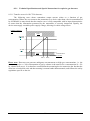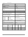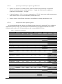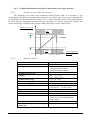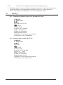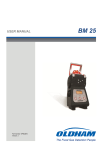
1
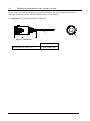
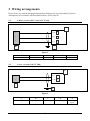
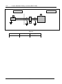
USER MANUAL OLC/OLCT 20 Gas Detector Part Number: NPO20GB Revision: C.2 The Fixed Gas Detection Experts GAS DETECTION We are delighted that you have chosen an OLDHAM instrument and would like to thank you for your choice. We have taken all the necessary measures to ensure that your instrument provides total satisfaction. Now it is important to read this document carefully. EXTENT OF RESPONSIBILITY * OLDHAM declines its responsibility towards any person for material damage, physical injury or death resulting wholly or partly from inappropriate use, installation or storage of its equipment resulting from failure to observe instructions and warnings and/or standards and regulations in force. * OLDHAM neither supports nor authorises any company, physical or moral person to assume responsibility on behalf of OLDHAM, even if it is involved in the sale of OLDHAM products. * OLDHAM cannot be held responsible for direct or indirect damage or be required to pay direct or indirect compensation resulting from the sale or use of any of its products IF THESE PRODUCTS HAVE NOT BEEN DEFINED AND CHOSEN BY OLDHAM FOR THEIR SPECIFIC USE. CLAUSES CONCERNING PROPERTY * Drawings, plans, specifications and information included in this document contain confidential information that is the property of OLDHAM. * None of this information may be reproduced, copied, divulged or translated, by physical, electronic or any other means, nor used as the basis for the manufacture or sale of OLDHAM equipment or for any other reasons without prior consent from OLDHAM. WARNINGS * This document is not contractually binding. In the interests of its customers, OLDHAM reserves to modify the technical specifications of its equipment without notice, in order to improve its performance. * READ THIS MANUAL CAREFULLY BEFORE FIRST USE OF THE EQUIPMENT: this manual must be read by any person who is or will be responsible for using, maintaining or repairing this equipment. * This equipment will only provide the announced performance levels if it is used, maintained and repaired according to OLDHAM directives, by OLDHAM personnel or by personnel approved by OLDHAM. GUARANTEE 2 years guarantee in normal conditions of use on parts and technical labour, return in our workshops, excluding consumables (sensors, filters, etc.) 2 CONTENTS 1 Description ................................................................................................... 5 1.1 General ..........................................................................................................................5 1.2 Main characteristics of the various versions .................................................................5 1.3 Mechanical installation of the various versions ............................................................6 2 Wiring arrangements .................................................................................. 7 2.1 3-Wire version (OLC 20d, OLCT 20d) ........................................................................7 2.2 2-wire versions (OLCT 20d).........................................................................................7 2.3 2-wire Intrinsic Safety versions (OLCT 20i) ................................................................8 3 Maintenance ................................................................................................. 9 3.1 Detector OLC 20 ...........................................................................................................9 3.1.1 Calibration ...............................................................................................................9 3.1.2 Replacing a sensor on an OLC 20 .........................................................................10 3.2 Transmitters OLCT 20 ................................................................................................10 3.2.1 Calibration .............................................................................................................10 3.2.2 Calibration specifications ......................................................................................12 3.3 Replacing a sensor on OLCT 20 .................................................................................12 3.4 Disposal of OLC(T) 20 ...............................................................................................12 4 Spare Parts ................................................................................................. 13 4.1 OLC 20 flameproof gas detector ................................................................................13 4.2 OLCT 20 flameproof gas detector ..............................................................................13 4.3 OLCT 20 Intrinsic Safety detector..............................................................................14 5 Accessories ................................................................................................. 15 6 Technical characteristics of OLC 20 ....................................................... 17 7 Technical characteristics of OLCT 20..................................................... 17 8 Specific Instructions for use in Explosive Atmospheres according to European Directive ATEX 94/9/EC ........................................................ 19 8.1 Specifications for mechanical and electrical installation in Classified Areas. ...........19 8.1.1 Flameproof detectors (d) .......................................................................................19 8.1.2 Intrinsic safety detectors (i) OLCT 20 i ................................................................19 3 8.2 Metrological specifications for explosive gas and oxygen measurement detectors ...20 8.2.1 Technical Specifications and Special Instructions for explosive gas detectors ....21 8.2.2 Technical Specifications and Special Instructions for Oxygen detectors .............25 8.3 Markings .....................................................................................................................26 8.3.1 Flameproof certified version: OLC 20d and OLCT 20 d......................................26 8.3.2 Intrinsic safety version: OLCT 20 i ......................................................................26 9 Recommendations ..................................................................................... 27 10 EC Declaration of Conformity ................................................................. 29 4 1 Description 1.1 General OLC 20 gas detectors are catalytic type detectors intended for the detection of combustible gases. They are flameproof certified (OLC 20d). OLCT 20 gas detectors are 4-20 mA transmitters and are intended for the measurement of combustible and toxic gases and oxygen. They are either flameproof certified (OLCT 20d) or intrinsically safe certified (OLCT 20i). OLC 20s and OLCT 20s are available in ¾ NPT or M25 screw fittings and are designed to be attached on a junction box or any compatible generic transmitters. 1.2 Main characteristics of the various versions OLC 20 Flameproof design OLCT 20 LEL LEL TOX/O2 X X X Intrinsic safety design X 3-wire cable / Wheatstone bridge X 3-wire cable / 4-20 mA output X 2-wire cable / 4-20 mA output X Catalytic sensor X X Electrochemical sensor X Replaceable sensor X Replaceable and pre-calibrated sensor 5 X X 1.3 Mechanical installation of the various versions Please ensure you read the paragraph: Special Specifications for use in Potentially Explosive Atmospheres in Accordance with European Directive ATEX 94/9/EC See Appendix 1 for general installation instructions. A Figure 1 : Dimensions A Dimensions OLC/OLCT 20 Cable length 0.2 m 6 2 Wiring arrangements Please ensure you read the paragraph: Special Specifications for use in Potentially Explosive Atmospheres in Accordance with European Directive ATEX 94/9/EC 2.1 3-Wire version (OLC 20d, OLCT 20d) A 1 1 (S) E 2 2 (-) D 3 3 (+) D C B Figure 2 A B C D E OLDHAM controller OLC or OLCT 20 Grounding Power supply Signal (I) 2.2 2-wire versions (OLCT 20d) A 3 3 (+) D 1 1 (-/S) E B C Figure 3 A B C D E OLDHAM controller OLC 20 or OLCT 20 Grounding Power supply Power supply Signal 7 2.3 2-wire Intrinsic Safety versions (OLCT 20i) Hazardous area Safe area A B C Figure 4 A B C OLDHAM controller OLC 20 or OLCT 20 ZENER Barrier 8 3 Maintenance The operations and adjustments described in this chapter must be performed by authorized personnel only as they can affect the appliance's reliability in detection. It is prohibited to open the transmitter when energized 3.1 Detector OLC 20 Gas detection instruments are potential life-saving devices. Recognizing this fact, OLDHAM Corporation recommends that a functional “bump” test be performed on every fixed gas-monitoring instruments as part of a regular maintenance program. A functional test is defined as a brief exposure of the detector to a concentration of gas(es) in excess of the lowest alarm set-point for each sensor for the purpose of verifying sensor and alarm operation and is not intended to be a measure of the accuracy of the instrument. OLDHAM further recommends that a full instrument calibration be performed using a certified concentration(s) of calibration gas(es) quarterly, every 3 months.* Calibrations may be necessary more or less frequently based, for example, on application, field conditions, exposure to gas, sensor technology, and environmental conditions. The frequency of calibration is best determined by company policy or local regulatory agencies. If an instrument fails to operate properly during any functional “bump” test, a full instrument calibration should be performed successfully prior to use. These recommendations are based on safe work procedures, industry best practises, and regulatory standards to ensure worker safety. OLDHAM is not responsible for setting safety practices and policies. * For new installations it may be prudent to carry out bump tests frequently at first (perhaps weekly), increasing the time intervals (to, perhaps, monthly or more) as confidence grows with experience in the installation concerned, on the basis of the maintenance record. 3.1.1 Calibration On the controller On the detector Set the measuring channel to the calibration position (alarm relays inhibited) Apply the calibration cup and perform the calibration in accordance with the procedure defined during the training course provided by OLDHAM or by an OLDHAM’s authorized person Proceed the zero and span Set the measuring channel back to the "normal" position and make sure that it is working properly. 9 3.1.2 Replacing a sensor on an OLC 20 When? - When the sensor is damaged or cannot be calibrated On a preventive basis How? - Turn off the relevant measuring channel - Remove the sensor to be replaced - Replace it with a new sensor - Turn on the channel back and check that it operates correctly (see the following page for more information) 3.2 Transmitters OLCT 20 OLCT 20 gas transmitters are equipped with a pre-calibrated sensor and do not require any adjustment on installation. However, as gas detectors are safety equipment, it is recommended to bump test the complete transmitter after a sensor replacement. 3.2.1 Calibration After removing the sensor from the transmitter, perform the calibration by using the calibrating bench provided for that purpose (see CALIBRO’s user manual). 10 Procedure On the detector On the controller Set the measuring channel to the calibration position (alarm relays inhibited) Loosen the locking screw 1 Rotate the sensor module then extract it 2 Once calibrated put the sensor back in place or use a replacement sensor and reinstall the whole assembly. Set the measuring channel back to the "normal" position and make sure that it is working properly. 11 3.2.2 Calibration specifications Calibration shall be performed outside classified areas and by using suitable equipment that is described during the training course provided by OLDHAM or by a person authorized by OLDHAM. item 1 OLCT 20 sensor module (LEL/TOX/O2) item 2 3.3 - Adjustment of 0 in clean air, using potentiometer (item 1). - Adjustment of sensitivity (with standard gas), using the potentiometer (item 2). Replacing a sensor on OLCT 20 When? - When the sensor is damaged or cannot be calibrated. On a preventive basis. - Switch off the relevant measuring channel. Remove the sensor to be replaced. Replace it with a new, precalibrated unit. Switch the channel back on and check that it operates correctly. How? 3.4 Disposal of OLC(T) 20 Concerning the conservation, of the protection and the improvement of the quality of the environment, as well as for the protection of the health of the persons and the careful and rational use of natural resources, OLCT 20 has to be the object of a selective collection for the electronic equipments and cannot be scrapped with the normal domestic waste. The user thus has the obligation to separate the OLCT 20 of the other waste so as to guarantee that it is recycled in a sure way at the environmental level. For more details of the existing sites of collection, contact the local administration or the distributor of this product. 12 4 Spare Parts Use only genuine spares, otherwise the reliability of the equipment could be adversely affected 4.1 OLC 20 flameproof gas detector Flameproof replacement sensors Part number Replacement sensor (VQ1 – standard) 6313757 Replacement sensor (AP – poison resistant) 6313758 Catharometric sensor 6313759 4.2 OLCT 20 flameproof gas detector Flameproof replacement sensors Part number OLCT 20, 0-100% LEL (VQ1) 6313685 OLCT 20, 0-100% LEL (AP) 6313974 OLCT 20, 0-100% vol. (catharometer) 6313687 0 – 100 ppm 0 – 300 ppm 0 - 1000 ppm 6313690 6313691 6313692 OLCT 20 H2S, 0 – 30 ppm OLCT 20 H2S, 0 – 100 ppm OLCT 20 H2S, 0 - 1000 ppm 6313695 6313696 6313697 OLCT 20 NO, OLCT 20 NO, OLCT 20 NO, 0 – 100 ppm 0 – 300 ppm 0 - 1000 ppm 6313698 6313699 6313700 OLCT 20 H2, 0 - 2000 ppm 6313706 OLCT 20 NH3, 0 – 100 ppm OLCT 20 NH3, 0 - 1000 ppm 6313707 6313708 OLCT 20 O2, 6313710 OLCT 20 CO, OLCT 20 CO, OLCT 20 CO, 0 - 0–30% vol. 13 4.3 OLCT 20 Intrinsic Safety detector INTRINSIC SAFETY SENSORS (SI) Part number 0 – 100 ppm 0 – 300 ppm 0 - 1000 ppm 6313711 6313712 6313713 OLCT 20 H2S, 0 – 30 ppm OLCT 20 H2S, 0 – 100 ppm OLCT 20 H2S, 0 - 1000 ppm 6313716 6313717 6313718 0 – 100 ppm 0 – 300 ppm 0 - 1000 ppm 6313719 6313720 6313721 OLCT 20 CO, OLCT 20 CO, OLCT 20 CO, OLCT 20 NO, OLCT 20 NO, OLCT 20 NO, OLCT 20 NO2, 0 – 10 ppm OLCT 20 NO2, 0 – 30 ppm 6313722 6313723 OLCT 20 SO2, 0 – 10 ppm OLCT 20 SO2, 0 – 30 ppm OLCT 20 SO2, 0 - 100 ppm 6313724 6313725 6313726 0 – 2000 ppm 6313727 OLCT 20 NH3, 0 – 100 ppm OLCT 20 NH3, 0 - 1000 ppm 6313728 6313729 OLCT 20 H2, 0 – 30 ppm 0 - 100 ppm 6313730 6313731 OLCT 20 HCN, 0 – 30 ppm OLCT 20 HCN, 0 - 100 ppm 6313732 6313733 OLCT 20 HCl, OLCT 20 HCl, OLCT 20 Cl2, 0 – 10 ppm 6313734 OLCT 20 O3, 0 – 1 ppm 6313735 OLCT 20 COCl2, 0 – 1 ppm 6313736 OLCT 20 PH3, 0 – 1 ppm 6313737 OLCT 20 AsH3, 0 – 1 ppm 6313738 OLCT 20 HF, 0 – 10 ppm 6313739 OLCT 20 ClO2, 0 – 3 ppm 6313740 OLCT 20 ETO, 0 – 30 ppm 6313746 OLCT 20 SiH4, 0 – 50 ppm 6313747 OLCT 20 O2, 0 – 30% vol. 6313748 14 5 Accessories TOOL KIT 6147869 CALIBRATION CUP 6331141 BY-PASS ADAPTOR for combustible gases, CO, H2S, O2 6327910 PLASH GUARD 6329004 PROTECTIVE FILTER, PTFE 6335975 ACTIVE CARBON FILTER 6335976 REMOTE CALIBRATION CUP (for combustible gases only) 6327911 15 16 6 Technical characteristics of OLC 20 Power supply: Power consumption: Measurement signal: Line length (shielded cable): Output signal Ingress Protection Weight Dimensions voltage on detector terminals = 2.8 V max 3-wire version = 400 mA max Wheatstone bridge 3-wire version = 1 km as 3x 1.5 mm2 (32 ohms in loop mode) mV bridge output, 3 wires IP66 800 g 60 X 120 mm 7 Technical characteristics of OLCT 20 A) Explosion-proof version Power supply: Power consumption: Load resistance: Line length (shielded cable): B) voltage on detector terminals = 15 V to 30 V 3-wire version = 100 mA 2-wire version = 25 mA maximum resistance = 250 ohms 3-wire version = 1 km as 3x 1.5 mm2 (32 ohms in loop mode) 2-wire version = 4 km as 3x 1.5 mm2 (32 ohms in loop mode) Intrinsic safety version Characteristics of ZENER barrier: Supply voltage for barrier: Voltage on detector terminals: Power consumption: Load resistance: Line length (shielded cable): 28 V - 300 ohms 19 V to 26 V 10 V to 26 V 25 mA max 47 ohms 1 km as 3x 1.5 mm2 (32 ohms in loop mode) Output signal Source mode current Max. current Fault current 4-20 mA 25 mA <1 mA Miscellaneous Ingress Protection Weight Dimensions IP66 800 g 60 X 120 mm 17 18 8 Specific Instructions for use in Explosive Atmospheres according to European Directive ATEX 94/9/EC The OLC/OLCT 20 gas detectors comply with the requirements of European Directive ATEX 94/9/EC relating to explosive Dust and Gas atmospheres. As a result of their metrological performance, as tested by the Approval Agency INERIS, the OLC/OLCT 20 gas detectors designed to measure explosive gasses and oxygen are classified as safety devices and may therefore contribute to limiting the risk of explosion. The information contained in the following paragraphs should be respected and taken into account by the manager of the site where the equipment is installed. Please refer to the provisions of European Directive ATEX 1999/92/EC on improving health and safety conditions for workers exposed to potentially explosive atmospheres. 8.1 Specifications for mechanical and electrical installation in Classified Areas. Installation will comply with all applicable standards, and particularly with EN 60079-14 and EN 60079-17. 8.1.1 Flameproof detectors (d) - These detectors are intended for use in surface industries II, Category 2, zones 1 and 2 (Gas) and zones 21 and 22 (Dust) in ambient temperature from -20°C to +70°C. - Cables will be mechanically protected. - The transmitter casing will be earthed using the external or internal terminal, which should be corrosion-protected. Users should clean detectors regularly in order to prevent any external accumulation of dust. - Mechanically, detectors will be installed such that the detection sensor points downwards. Any variance of over 45° from the vertical will result in measurement errors. - Where connections are located in a classified zone, they will be enclosed in approved envelopes. - The width of the threaded joint of cable gland is superior to the value specified in the table of EN 60079-1 standard. 8.1.2 Intrinsic safety detectors (i) OLCT 20 i - These detectors are intended for use in surface industries II, Category 1, zones 0, 1 and 2 (Gas) and zones 20, 21 and 22 (Dust). They are also intended for use in coal mines, Category M1. The ambient operating temperature range is –20°C to +70°C. - Users should clean detectors regularly in order to prevent any external accumulation of dust. - The person responsible for IS installation (the “System Designer”) must draw up a system document demonstrating that every aspect of the Power Cable Detector system complies with intrinsic safety. - They must be powered by an intrinsic safety source: 28V - 300 ohms - Where connections are located in a classified zone, they will be enclosed in approved envelopes. - The safety parameters applying to the OLCT 20i detectors are : Ui (V) Ii (mA) Pi (mW) Ci (nF) Li (H) 28 94 658 40 15μH 19 8.2 Metrological specifications for explosive gas and oxygen measurement detectors In case of exposure above the measuring range, it is mandatory to bump test the instrument with gas and/or to perform a calibration. In the event of a change of position, it is necessary to re-calibrate the detector. The OLC/OLCT 20 transmitter sensors intended to measure explosive gasses and oxygen are classified as safety devices and may therefore contribute to limiting the risk of explosion. Detectors comply with the following European standards: Explosive gas detectors: - OLC 20 explosive gas detectors comply with European standards EN 50054 and EN 50057 for Methane (calibration gas), Propane and Hydrogen (gasses following response curves) where they are used with the following OLDHAM controllers SV 4B, MX 15, MX 32, MX 42A, MX 43, MX 48 and MX 52. - OLCT 20 explosive gas detectors comply with European standards EN 50054 and EN 50057 for Methane (calibration gas), Propane and Hydrogen (gasses following response curves), where they are used with SV 4B, MX 15, MX 32, MX 42A, MX 43, MX 48, MX 52 and MX 62 OLDHAM controllers, or where they are connected to measurement devices with 4-20 mA inputs in accordance with paragraph 1.5 of Appendix II of the ATEX 94/9/EC Directive and are compatible with their characteristics (cf. transfer curve). Oxygen detectors: - OLCT 20 oxygen detectors comply with European Standard EN 50104 where they are used with MX 15, MX 32, MX 42A, MX 43, MX 48, MX 52 and MX 62 OLDHAM controllers, or where they are connected to measurement devices with 4-20 mA inputs in accordance with paragraph 1.5 of Appendix II of the ATEX 94/9/EC Directive and are compatible with their characteristics (cf. transfer curve). 20 8.2.1 Technical Specifications and Special Instructions for explosive gas detectors 8.2.1.1 Transfer curves for OLCT 20 detectors The following curve shows transmitter output current values as a function of gas concentration. Where the user connects the transmitter to a device other than a device manufactured by OLDHAM, he must check that the transfer curve is fully compatible with its input characteristics to ensure that the information generated by the transmitter is correctly interpreted. Equally, the device must supply a suitable power supply voltage, allowing for cable voltage losses. Output Current in mA Fault 23.2 mA 20.0 mA 4.0 mA 1 mA Fault 0% Concentration in % LEL 100 % 120% Please note: Detectors can generate ambiguous measurements at high gas concentrations, i.e. the current output for a > 20% concentration of gas by volume is the same as for a concentration of < 5% by volume (bell curve). It is therefore essential that the measuring device memorises the fact that the value has exceeded the scale and that resetting is manual rather than automatic, and follows the safety regulations specific to the site. 21 8.2.1.2 Metrological data Type VQ1 Maximum concentration 100% LEL Principle Catalytic Estimated service life > 36 months Away from air -10°C < T < 35°C Storage 10% < RH < 60%. Maximum 6 months -20°C to +55°C 0% RH to 95% RH 1 bar ± 10% Between 0% and 70% LEL: 1% LEL Continuous temperature range Humidity range Pressure range Linearity variance (methane scale) Between 70% and 100% LEL: 7% LEL ± 2% of the value measured, or ± 1 LEL Measurement reproducibility (or ± 0.05% CH4) Long-term drift Zero point: < 5% methane LEL per year in normal Sensitivity: Typical drift values operating Methane < 20% of the value measured per year conditions Propane/Butane < 10% of the value measured per year Effect of humidity (10% to 90% RH) at ± 5% of relative sensitivity 40°C Maximum recommended interval between calibrations (normal operating conditions) Calibration concentration Response time gas and (may vary ± 10% concentration between sensors) injected 6 months 30– 80% LEL Methane Hydrogen Pentane (50% LEL) (50% LEL) (52% LEL) Styrene (45% LEL) t25 4 sec 3 sec 8 sec 12 sec t50 8 sec 6 sec 12 sec 40 sec t90 15 sec 10 sec 27 sec 60 sec 22 8.2.1.3 Special precautions for explosive gas detectors Sensors are sensitive to certain poisons, which can reduce their sensitivity: emission of silicone-containing vapours at concentrations > 10 ppm and chlorinated or sulphurous products at concentrations > 100 ppm. A lack of oxygen (< 15% O2) or over-oxygenation (> 23% O2) may cause under-measurement (in the former case) or over-measurement (in the latter case). Sensors must be located head downwards at installation or during maintenance work. 8.2.1.4 Response to other explosive gasses It is recommended that the detector is calibrated using the gas to be measured. Users wishing to calibrate the detector using a gas other that detected and factory-programmed should refer to the following table, and use the recommended gas and corresponding coefficient. Table 1 : Calibration Coefficients Gas Ethyl acetate Acetone Acetylene Acrylic acid Chemical Formula LEL LSE (%) (%) Flash point (°C) - - Vapor Coefficient Coefficient Coefficient Coefficient density Calibration gas Calibration gas - Calibration gas - Calibration gas CH4 (methane) H2 (Hydrogen) C4H10 (Butane) C5H12 (Pentane) C4H8O2 2,10 11,50 -4 3,0 1,65 1,35 0,90 0,80 C3H6O 2,15 13,00 -18 2,1 1,65 1,35 0,90 0,80 C2H2 1,50 100 -18 0,9 2,35 1,90 1,25 1,15 C3H4O2 2,40 8,00 54 2,5 5,00 4,00 2,65 2,40 Butyl acrylate C7H12O2 1,20 8,00 37 4,4 3,50 2,80 1,85 1,70 Ethyl acrylate C5H8O2 1,70 13,00 -2 3,5 3,05 2,45 1,65 1,50 C3H3N 2,80 28,00 -1 1,8 1,45 1,20 0,80 0,70 Ammoniac NH3 15,00 30,20 < -100 0,6 0,90 0,75 0,50 0,45 Benzene C6H6 1,20 8,00 -11 2,7 4,00 3,20 2,15 1,90 1.3Butadiene C4H6 1,40 16,30 -85 1,9 2,55 2,05 1,35 1,25 Butane C4H10 1,50 8,50 -60 2,0 1,90 1,55 1,00 0,90 Butanol (Butyl Alcool) C4H10O 1,4 11,3 29 2,6 1,95 1,60 1,05 0,95 2 - Butanone (MEK) C4H8O 1,80 11,50 -4 2,5 3,90 3,15 2,10 1,90 Cyclohexane C6H12 1,20 8,30 -17 2,9 2,00 1,60 1,10 1,00 Dimethylether C2H6O 3,00 27,00 -41 1,6 1,80 1,45 0,95 0,90 Dodecane C12H26 0,60 ~6,0 74 5,9 4,00 3,20 2,15 1,90 Ethane C2H6 3,00 15,50 135 1,0 1,50 1,20 0,80 0,75 Ethanol C2H6O 3,30 19,00 13 1,6 2,15 1,75 1,15 1,05 Ether (C2H5)2O (Diethylether) 1,70 36,00 -45 2,6 1,90 1,55 1,00 0,90 Ethylene C2H4 2,70 34,00 - 135 1,0 1,65 1,35 0,90 0,80 LPG Prop+But 1,65 ~9,0 < -50 1,9 1,90 1,55 1,00 0,90 Diesel Melange 0,60 ~6,0 55 >4 3,20 2,60 1,70 1,55 CH4 5,00 15,00 -188 0,6 1,05 C7H16 1,10 6,70 -4 3,5 2,20 1,80 1,20 1,05 Acrylonitrile Natural Gas Heptane 23 Gas Hexane Chemical Formula LEL LSE (%) (%) Flash point (°C) - - Vapor Coefficient Coefficient Coefficient Coefficient density Calibration gas Calibration gas - Calibration gas - Calibration gas CH4 (methane) H2 (Hydrogen) C4H10 (Butane) C5H12 (Pentane) C6H14 1,20 7,40 -23 3,0 1,15 1,00 Hydrogen H2 4,00 75,60 - 0,069 Isobutane C4H10 1,50 8,40 -83 2,0 1,50 1,20 0,80 0,75 Isobutene C4H8 1,60 10,00 <-10 1,9 2,20 1,80 1,20 1,05 Isopropanol C3H8O 2,15 13,50 11,7 Kerosene (JP4) C10 C16 2,1 1,60 1,30 0,85 0,80 0,70 5,00 > 50 >4 5,00 4,00 2,65 2,40 C5H8O2 2,10 12,50 2 3,5 2,25 1,80 1,20 1,10 Methane CH4 5,00 15,00 -188 0,55 1,00 Methanol CH3OH 5,50 44,00 11 1,1 1,40 1,15 0,75 0,70 Naphta melange (Mixture) 0,90 5,90 > 44 >4 3,50 2,80 1,85 1,70 Nonane C9H20 0,70 5,60 31 4,4 4,40 3,55 2,35 2,10 Octane C8H18 1,00 6,00 12 3,9 2,70 2,20 1,45 1,30 Ethylene Oxyde C2H4O 2,60 100 -20 1,5 2,10 1,70 1,15 1,00 Propylene oxide C3H6O 1,90 37,00 70 2,0 2,35 1,90 1,25 1,15 Pentane C5H12 1,40 8,00 -49 2,5 Propane C3H8 2,00 9,5 -104 1,6 1,55 1,25 0,85 0,75 Propylene C3H6 2,00 11,70 -107,8 1,5 1,65 1,35 0,90 0,80 Styrene C8H8 1,1 8,00 31 3,6 6,30 5,05 3,35 3,00 / 1,10 ~6,0 21 3à4 1,80 1,45 0,95 0,90 C7H8 1,20 7 5 3,1 4,00 3,20 2,15 1,90 - 0,8 6,0 35 4,7 3,50 2,80 1,85 1,70 Triethyl amine C6H15N 1,20 8 -15 3,5 2,05 1,65 1,10 1,00 White Spirit melange (Mixture) 1,10 6,50 >30 >4 3,50 2,80 1,85 1,70 C8H10 1,00 7,60 25 3,7 4,00 3,20 2,15 1,90 Methyl Methacrylate Gasoline lead free Toluene Turpentine Oil Xylene 2,10 1,70 1,00 1,00 Sensors with a grey background: gases recommended for calibrating the detector (VQ1) Example (second row of table): calibration of an Acetone detector using 1% butane (by volume) as the calibrating gas. Value to be displayed: 1% (butane injected) x 100 x 0.90 (Butane/Acetone coefficient) = 60% LEL 1.5% (butane LEL) N.B.: - LELs vary depending on the source. Those values shown here are taken from European Standard EN 50054 Coefficients are accurate to 15% 24 8.2.2 Technical Specifications and Special Instructions for Oxygen detectors 8.2.2.1 Transfer curves for OLCT 20 detectors The following curve shows the transmitter output current value as a function of gas concentration. Where the user connects the transmitter to a device other than a device manufactured by OLDHAM, he must check that the transfer curve is fully compatible with its input characteristics to ensure that the information generated by the transmitter is correctly interpreted. Equally, the device must supply a suitable power supply voltage, allowing for cable voltage losses. Output Current in mA Fault 23.2 mA 20.0 mA 4.0 mA 1 mA Fault 0% 8.2.2.2 % O2 concentration by volume 30.0 % 36.0% Metrological data Maximum concentration Type and number Principle Estimated service life Storage Temperature range Humidity range Pressure range Accuracy at 20°C Repeatability T90 response time Effect of temperature (0 to 40°C) Effect of humidity (10% to 90% RH) Sensitivity drift over time Zero stabilisation time following power-up 25 30% O2 CT5020 CELL 2-electrode electrochemical (Measurement of oxygen concentration by volume) 30 months 4°C < T < 12°C 10% < RH < 60% -20°C to +45°C 20% RH to 95% RH 1 bar ± 10% 15 to 21% O2 ± 0.5% vol O2 1 to 14% O2 ± 0.6% vol O2 < 2% of signal < 15 seconds < 0.5% vol O2 The measurement is lower as a result of the air being diluted by water vapour < 2% per month 30 to 60 minutes 8.2.2.3 8.3 Characteristics and Special precautions for oxygen detectors When the transmitter is powered up or the measurement sensor is replaced, it takes between 30 and 60 minutes for the measurement to stabilise at 20.9% v/v in pure ambient air. The use of an oxygen-rich atmosphere (> 25%) can compromise safety. Markings 8.3.1 Flameproof certified version: OLC 20d and OLCT 20 d OLDHAM F – 62027 Arras 0080 OLC 20d or OLCT 20d II 2GD Ex d IIC T6 Gb Ex tb IIIC T85°C Db IP66 Tamb : -20°C to 70°C INERIS 01ATEX0004X Read instruction manual WARNING: Do not open when energized Serial number, year of manufacture 8.3.2 Intrinsic safety version: OLCT 20 i OLDHAM F – 62027 Arras 0080 OLCT 20i II 1 GD Ex ia IIC T4 Ga Ex ia IIIC T135°C Da IP66 I M1 Ex ia I Ma Tamb : -20°C to 70°C INERIS 01ATEX0004X Read instruction manual WARNING: Do not open when energized Serial number, year of manufacture 26 9 Recommendations The measuring sensor shall be positioned facing downwards. The physical location of the TRANSMITTER depends on the type of gas to be detected: at the high point if the gas is lighter than air, at the low point if the gas is heavier than air, near outlet vents in the case of mechanical ventilation, or, more generally, in locations where the gas is likely to accumulate. Despite its high degree of protection (IP66), it may be necessary to protect the TRANSMITTER against adverse weather conditions (rain, dust, direct sunlight, etc.) and from direct spraying with cleaning or maintenance products (causing soiling of the detection sensor). The TRANSMITTER must also be positioned so as to allow access to the measuring sensor so that it can be replaced. Detectors must be positioned so as to optimize the detection of accumulations of gas emitted in the air. Factors to be considered in determining optimal detector positioning: potential sources of gas and vapour emissions chemical and physical data on gases and vapours which may be present liquids with low volatility detectors as near as possible to the leak risk area type and concentration of gas leaks (high-pressure jet, slow leak, etc.) air movements - indoors: natural and mechanical ventilation outdoors: wind speed and direction effect of temperature installation so as to avoid mechanical damage or deterioration caused by water in summer positioning to allow easy maintenance, if possible avoiding direct sunlight on the readout area as this would lead to maintenance problems 27 28 10 EC Declaration of Conformity 29 30 31 The Fixed Gas Detection Experts EUROPEAN PLANT AND OFFICES Z.I. Est – rue Orfila CS 20417 – 62027 Arras Cedex FRANCE Tél: +33 (0)3 21 60 80 80 – Fax: +33 (0)3 21 60 80 00 Website: http://www.oldhamgas.com AMERICAS Tel: +1-713-559-9280 Fax: +1-281-292-2860 [email protected] ASIA PACIFIC Tel: +86-21-3127-6373 Fax: +86-21-3127-6365 [email protected] EUROPE Tel: +33-321-608-080 Fax: +33-321-608-000 [email protected]