1
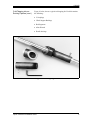
Liquid
Transducer
Installation Guide
10/28/99
Process Control Instrument Division
Liquid Transducer
Installation Guide
User’s Manual
914-002D
10/28/99
Table of Contents
Introduction . . . . . . . . . . . . . . . . . . . . . . . . . . . . . . . . . . . . . . . . . . . . . . . . . . . . . . . . . . . . . . . . . . . . . . 1
Description of
Flowcells and
Transducers . . . . . . . . . . . . . . . . . . . . . . . . . . . . . . . . . . . . . . . . . . . . 3
General Guidelines for Transducer Position and Location . . . . . . . . . . . . . . . . . . . . . . . . . . . . . . . . . . 4
Installing Wetted Transducers . . . . . . . . . . . . . . . . . . . . . . . . . . . . . . . . . . . . . . . . . . . . . . . . . . . . . . . . 5
Tilted Diameter Flowcells . . . . . . . . . . . . . . . . . . . . . . . . . . . . . . . . . . . . . . . . . . . . . . . . . . . . . . . . 5
Axial-Path Offset Flowcells . . . . . . . . . . . . . . . . . . . . . . . . . . . . . . . . . . . . . . . . . . . . . . . . . . . . . . 7
Creating Flowcells . . . . . . . . . . . . . . . . . . . . . . . . . . . . . . . . . . . . . . . . . . . . . . . . . . . . . . . . . . . . . . . . . 8
Installing a Spoolpiece. . . . . . . . . . . . . . . . . . . . . . . . . . . . . . . . . . . . . . . . . . . . . . . . . . . . . . . . . . . 8
Cold Tapping into an Existing Pipeline. . . . . . . . . . . . . . . . . . . . . . . . . . . . . . . . . . . . . . . . . . . . . . 9
Mounting Transducers into the Flowcell. . . . . . . . . . . . . . . . . . . . . . . . . . . . . . . . . . . . . . . . . . . . 13
Using Pan-Adapta Precision Plugs . . . . . . . . . . . . . . . . . . . . . . . . . . . . . . . . . . . . . . . . . . . . . . . . 16
Installing Clamp-On Transducers . . . . . . . . . . . . . . . . . . . . . . . . . . . . . . . . . . . . . . . . . . . . . . . . . . . . 20
Clamp-On Transducer Types. . . . . . . . . . . . . . . . . . . . . . . . . . . . . . . . . . . . . . . . . . . . . . . . . . . . . 20
Clamping with Stainless Steel Straps . . . . . . . . . . . . . . . . . . . . . . . . . . . . . . . . . . . . . . . . . . . . . . 21
Couplants . . . . . . . . . . . . . . . . . . . . . . . . . . . . . . . . . . . . . . . . . . . . . . . . . . . . . . . . . . . . . . . . . . . . 22
Determining the Transducer Locations . . . . . . . . . . . . . . . . . . . . . . . . . . . . . . . . . . . . . . . . . . . . . 23
Using the Universal Clamping Fixture . . . . . . . . . . . . . . . . . . . . . . . . . . . . . . . . . . . . . . . . . . . . . 24
Mounting Transducers into the Clamping Fixture . . . . . . . . . . . . . . . . . . . . . . . . . . . . . . . . . . . . . . . . 32
Using the Small Pipe Clamping Fixture. . . . . . . . . . . . . . . . . . . . . . . . . . . . . . . . . . . . . . . . . . . . . . . . 36
Yoke and Strap for CTS Transducers . . . . . . . . . . . . . . . . . . . . . . . . . . . . . . . . . . . . . . . . . . . . . . . . . . 39
Using the Magnetic Clamping Fixture. . . . . . . . . . . . . . . . . . . . . . . . . . . . . . . . . . . . . . . . . . . . . . . . . 40
Liquid Transducer Installation Guide
i
10/28/99
Introduction
This guide is for Panametrics flowmeters that measure liquid flow
using an ultrasonic transit time method. In this method, two
transducers are mounted on a pipe, one upstream of the other. They
alternately transmit and receive ultrasonic pulses through the fluid.
The pulses that travel in the same direction as the fluid flow
(downstream) move slightly faster than the pulses that travel against
the flow (upstream). The flowmeter electronics, connected to the
transducers, measures how long it takes both the upstream and the
downstream ultrasonic pulses to travel from one transducer to the
other. This information is used to calculate flow velocity.
Caution!
A flowmeter’s accuracy and performance depends
on the location, spacing, and alignment of the
transducers. This Transducer Installation Guide
provides general instructions for locating and
installing most transducer types. However, the
specific spacing dimension S of your transducers
will be unique to your installation.
It is important to note that this installation guide provides information
for the most common installations only. However, this guide can also
be used for equipment not specifically mentioned here. Panametrics
can accommodate many special installations by using different
transducers and configurations. For special installations, Panametrics
will supply drawings of the nominal dimensions based on the
particular application.
This guide consists of the following four sections:
•
Description of Flowcell and Transducers
•
General Guidelines for Transducer Position and Location
•
Installing Wetted Transducers
•
Installing Clamp-on Transducers
We suggest that you read the first two sections carefully and then
refer to the appropriate section for the type of transducers you are
using. If you have any questions or problems, contact Panametrics
Applications Engineering or Field Applications Support Team for
assistance.
Liquid Transducer Installation Guide
1
10/28/99
Introduction (cont.)
2
Upon request, Panametrics can set up in-plant or on-site, hands-on
training seminars. For more information, contact your local
representative or one of the following Panametrics sales and
manufacturing offices:
Panametrics, Inc.
Panametrics, Ltd.
221 Crescent St., Suite 1
Bay 148, Shannon Airport
Waltham, MA 02453-3497
Shannon
USA
County Clare, Ireland
Tel.: 781-899-2719
Tel.: 353-61-471377
Fax: 781-894-8582
Fax: 353-61-471359
Liquid Transducer Installation Guide
10/28/99
Description of
Flowcells and
Transducers
A flowcell is the section of pipe where the transducers are mounted.
The flowcell can be created by mounting the transducers on the
existing pipeline, or on a spoolpiece. A spoolpiece is a precisionmanufactured section of matching pipe that contains the ports where
the transducers will be mounted. This setup allows more accurate
transducer alignment before mounting the spoolpiece into the
pipeline. If requested, the spoolpiece can be calibrated.
Transducers fall into one of two major classes: wetted or nonwetted. Wetted transducers are inserted into the pipe so that they
come in direct contact with the fluid being measured. Non-wetted
transducers, commonly referred to as clamp-ons, are clamped on the
outside of the pipe and send their ultrasonic pulses through the pipe
wall.
Panametrics standard wetted transducers are typically flat-faced and
send their ultrasonic longitudinal wave signals into the fluid with no
refraction. Panametrics standard clamp-on transducers, on the other
hand, use refraction to transmit sound through the pipe wall and into
the liquid. Although 3/8-, 1/2-, 3/4-, and 1-in. transducer diameters
are most common, a variety of other sizes is available, depending on
the application.
Panametrics has also developed hybrid transducers that consist of two
parts: a fixed member and a removable, wetted transducer. The fixed
member is a special wetted pipe plug called a Pan-Adapta® plug.
This plug (fixed member) is mounted in the flowcell. The wetted
transducer can be temporarily and repeatedly coupled to the outside
face of the Pan-Adapta plug. In using the Pan-Adapta plug there is no
need to interrupt the process when servicing the hybrid transducer.
For high-temperature applications, the Bundle Waveguide
Technology™ (BWT) system can be used. The BWT system consists
of a Pan-Adapta plug and a transducer. The Pan-Adapta plug uses
waveguide bundles to efficiently concentrate a greater amount of the
transducer signal into the process. At the same time, it acts as a heat
buffer that protects the transducer from high temperatures to ensure
long life.
Liquid Transducer Installation Guide
3
10/28/99
General Guidelines for
Transducer Position
and Location
Whichever transducer type is selected for your installation, flowmeter
accuracy depends on proper transducer location, spacing, alignment,
and electronics programming. However, even though every
transducer installation has specific location considerations, the
following two-location guidelines apply to all transducers, regardless
of type:
1. To help assure a uniform flow profile, locate the flowcell so that
there are at least 10 pipe diameters of straight, undisturbed pipe
upstream and 5 pipe diameters of straight, undisturbed pipe
downstream from the point of measurement. Measure from the
center of the transducer at the pipe wall ID. “Undisturbed pipe”
means avoiding sources of turbulence such as valves, flanges,
elbows; avoiding swirl; and avoiding cavitation.
2. It is important to locate the transducers on a horizontal plane. This
specifically applies to mounting transducers on a horizontal pipe.
One transducer cannot be on top of the pipe and one on the
bottom, because the top of the pipe tends to accumulate gas and
the bottom tends to accumulate sediment. These can attenuate or
block the ultrasonic signal. There is no similar restriction with
vertical pipes. To ensure a full pipe, however, you should avoid
vertical downward flow. When using a wetted installation,
extended-well type transducers are preferred to keep the
transducer face free from gas or sediment that may tend to get
trapped in the transducer port.
4
Liquid Transducer Installation Guide
10/28/99
Installing Wetted
Transducers
There are two basic types of flowcell installations for wetted
transducers:
•
Tilted Diameter - for use with pipe sizes of approximately 50 mm
ID (2 in. pipe) and above.
•
Axial Offset - for use with pipe sizes of 50 mm ID (2 in. pipe) and
below. In practice, approximately 1 to 50 mm ID (.04 to 2 in. ID)
pipe sizes are included.
Tilted Diameter Flowcells A tilted diameter flowcell is so named because the transducers send
their pulses at a typical 45° angle across the diameter (or other chord)
of the pipe. This type of flowcell can be configured as a singletraverse or multiple-traverse installation.
Note: a. The mounting angle for the transducer is typically 45°, but
other angles (20°, 30°, or 60°) can be used as required.
b.Tilted diameter can also refer to paths that are off-diameter
such as the Mid-Radius path.
A single-traverse configuration consists of two transducers mounted
on opposite sides of the pipe so that the signal they transmit passes
through the fluid just once, at a typical 45° angle (Figure 1 below).
Top View
P = Distance that the signal travels
through the liquid from one
transducer to the other.
P
Downstream
O.D.
I.D.
Upstream
L = Projected distance of
acoustical path in liquid.
L
Figure 1: Single-Traverse Flowcell with L=Pipe I.D.
Liquid Transducer Installation Guide
5
10/28/99
Tilted Diameter Flowcells
(cont.)
A multiple-traverse configuration consists of two transducers
mounted on the pipe so that the signal traverses the fluid two or more
times before reaching the other transducer. See Figures 2 to 4, below,
for examples of commonly used installations.
P = Distance that the signal travels
through the liquid from one
transducer to the other.
P
I.D.
O.D.
L = Projected distance of
acoustical path in liquid.
L
Figure 2: Double-Traverse Flowcell
P = Distance that the signal travels
through the liquid from one
transducer to the other.
P
O.D.
I.D.
L
Figure 3: Multiple-Traverse Flowcell (Four Traverses)
S=
OD2-ID2
4
Figure 4: Mid-Radius, Single-Traverse, 2-Path Flowcell
6
Liquid Transducer Installation Guide
10/28/99
Axial-Path Offset
Flowcells
In axial-path offset flowcells, the walls of the pipe reflect the
ultrasonic signal. This allows the signal to remain in the fluid longer,
increasing the effective length L and path P of the signal, thus
increasing accuracy. The number of times the signal can traverse the
fluid depends on such factors as transducer frequency, pipe size, pipe
wall condition, and the fluid being measured.
Axial-path offset flowcells can be made up as a spoolpiece, then
mounted into the pipeline, or they can be created by cold tapping the
transducer ports directly into the existing pipeline.
Figure 5 below shows an axial-path offset flowcell that is used for
1/8- to 2- in. pipe sizes. This type of flowcell maintains accuracy of
measurement on small diameter pipes because it provides a much
longer path length and allows for 100% area averaging of the flow
profile. An axial-path offset flowcell can be installed into the pipeline
using flanging, welding, NPT threading, or quick-release methods, as
necessary. When installed, the flowcell should be positioned to avoid
gas entrainment or sediment deposition in front of the transducers.
CL
CL
FLOW INLET
FLOW OUTLET
TRANSDUCER
L
P
Figure 5: Axial-Offset Flowcell
Liquid Transducer Installation Guide
7
10/28/99
Creating Flowcells
This section describes how to create a flowcell using one of two
following methods:
•
Installing a spoolpiece
•
Cold tapping transducer ports into an existing pipeline
Note: Hot tapping of pressurized pipe is also possible. Contact
Panametrics for the separate equipment and instructions.
Installing a Spoolpiece
Spoolpieces can be either flanged or welded into the existing pipeline.
To position the spoolpiece into the pipeline (Figure 6 below):
1. Find the arrow mark and the word TOP marked on the data tag on
the spoolpiece. If the spoolpiece is flanged, two bolt holes should
straddle the centerline.
2. Place the spoolpiece in the pipeline so that the arrow mark is in the
direction of flow and the top is appropriately located. (Be sure the
transducer ports are in a horizontal plane.)
3. Bolt or weld the spoolpiece into place, as appropriate.
4. Go to the section that describes mounting the wetted transducers.
In general (including cases where the spoolpiece axis is not
horizontal), be sure that the installation does not allow gas or
sediment to deposit in the transducer ports. Otherwise the sound
waves will be attenuated or blocked entirely.
Note: Use extended-well transducers or extended-well
Pan-Adapta plugs for tilted diameter flowcells.
TOP VIEW
BOLT HOLES STRADDLE
CENTERLINE SYMMETRICALLY
END VIEW
FLOW
Data Tag
L
Figure 6: Top View of a Flanged Spoolpiece
8
Liquid Transducer Installation Guide
10/28/99
Cold Tapping into an
Existing Pipeline
To cold tap the transducer ports into a pipe, the pipe must be empty
and safe. Please note that there are reference drawings and kits for
cold tapping available (see Figure 9, page 11). Standard kits provide
alignment equipment for single-traverse installations only. The
following steps are general guidelines required to make a cold tap to
install the transducer ports:
!WARNING!
Be sure to follow all applicable safety codes and
safety procedures.
A. Welded Pipe
1. Measure and mark locations on the pipe where the transducer
ports are to be placed.
2. Cut two holes into the pipe at the port locations. This is usually
done by using a welding torch or drilling with specialized
equipment.
3. Place a rod through the two holes to help maintain the alignment
while you attach a contoured coupling or nozzle to each hole. Use
rod support bushings to hold the rod in the couplings or nozzle
(Figure 7 below).
4. Weld the couplings to the pipe.
5. Remove the rod and bushings from the pipe. (Now refer to the
next section on mounting the transducers.)
TOP VIEW
END VIEW
Alignment Rod
Contoured Coupling
Rod Support Bushing
O.D.
I.D.
S
Figure 7: Transducer Location for a Cold Tap (Single-Traverse Only)
Liquid Transducer Installation Guide
9
10/28/99
B. Non-Weldable Pipe
1. A saddle is used to attach a coupling to non-weldable pipe such as
wood, fiberglass, cement, concrete, cast iron, etc.
2. Measure and mark locations on the pipe where the transducer
ports are to be placed.
3. Cut or drill the two holes into the pipe at the port locations. The
may require special equipment such as templates or drill guides.
4. Prepare the pipe surface around the hole so that the O-ring seal in
the saddle will form a good seal. In many cases, this can be done
by coating the pipe with epoxy.
5. Place a rod through the two holes to help maintain the alignment
while you attach a contoured coupling or nozzle to each hole. Use
rod support bushings to hold the rod in the couplings or nozzle
(Figure 8 below).
6. Fully install saddle and tighten saddle bolts.
7. Remove rod and bushings and install transducers.
Rod
Bushing
Bolts removed
for clarity
Coupling on Saddle
Saddle
(2 pieces)
45°
L = PIPE OD
Figure 8: Non-Weldable Pipe with Attached Saddle
10
Liquid Transducer Installation Guide
10/28/99
Cold Tapping into an
Existing Pipeline (cont.)
Figure 9, below, shows a typical cold tapping kit. Each kit contains
the following:
•
2 Couplings
•
2 Rod Support Bushings
•
Rod Segments
•
Allen Wrench
•
Detail drawings
Figure 9: Cold Tapping Kit
Liquid Transducer Installation Guide
11
10/28/99
Cold Tapping into an
Existing Pipeline (cont.)
Note: Two nozzles (flanged) are available for cold tapping ports for
flanged transducers or Pan-Adapta plugs. The kit for the
nozzles includes two tapped flanges to accept the bushings
(Figure 10 below).
Bushing
Flanged Nozzle
Tapped Flange
Rod
D = Pipe ID
L = Pipe OD
Figure 10: Flanged Nozzles for Cold-Tapping
12
Liquid Transducer Installation Guide
10/28/99
Mounting Transducers
into the Flowcell
Standard transducers (Figure 11 below) and extended-well
transducers (Figure 12 below) typically have a 3/4-in. or 1-in.NPT
thread for the transducer-to-spool piece connection and for the
junction box connection, to protect the electrical connector.
Note: Transducers and Pan-Adaptas are marked with an inspection
number, a serial number, and a programming number. Make a
note of the programming number: it will be needed for
programming the meter.
Figure 11: Standard Wetted Transducer
1” NPT
Wrench Flat
1” NPT
Extended Well
Figure 12: Extended-Well Transducer
Liquid Transducer Installation Guide
13
10/28/99
Mounting Transducers
into the Flowcell (cont.)
Standard and extended-well transducers are easily modified for
hazardous areas by adding explosion-proof junction boxes (Figure 13
below).
!WARNING!
Be sure to follow all applicable safety codes and
safety precautions when installing transducers in
hazardous areas.
To weatherproof the transducers, you can use the same junction box
with the supplied O-ring seal.
Figure 13: Wetted Transducer in Junction Box
14
Liquid Transducer Installation Guide
10/28/99
Mounting Transducers
into the Flowcell (cont.)
Buffer rod transducers are used in high- or low-temperature
applications and are typically 6 in. long and have a 1-in. NPT thread
for the process connections. Figure 14 below shows a standard 6-in.
buffer rod transducer.
Wrench Flat
Figure 14: Buffer Rod Transducer
To mount the transducers or transducer-bearing Pan-Adaptas into a
flowcell, screw them into the mounting ports, using approximately
three layers of Teflon tape or other appropriate thread sealant (Figure
15 below). Tighten the transducer or Pan-Adapta with a wrench to
ensure the mounting will be leak-proof. Be sure to use the wrench
only on the hex nut of the standard transducer or the flats of the buffer
rod transducer.
Figure 15: Properly Mounted Wetted Transducer
Liquid Transducer Installation Guide
15
10/28/99
Using Pan-Adapta
Precision Plugs
The Pan-Adapta plug is a pipe plug and coupling assembly made of
stainless steel, other metals, or a plastic such as CPVC, PVDF, or
PTFE. The Pan-Adapta plug mounts into pipe couplings, nozzles, or
tees, enabling you to install and remove transducers easily without
interrupting the process or emptying the pipe.
Stainless steel and other metal Pan-Adapta plugs are screwed, socketwelded, or flanged into the pipe coupling, nozzle or tee.
Plastic Pan-Adapta plugs are mounted into a pipe coupling either by
threading or fuse bonding. Plastic Pan-Adaptas are used when wetted
parts cannot be metal. These adaptors have a thinner face than the
stainless steel plugs and require the use of extended-well wetted
transducers.
Figure 16 below shows standard threaded stainless steel and plastic
Pan-Adapta plugs. Figure 17 below shows extended-well threaded
stainless steel Pan-Adapta plugs.
Stainless Steel
Plastic
Figure 16: Standard Threaded Stainless Steel (left) and
Plastic Pan-Adapta Plugs
Figure 17: Extended-Well Threaded Pan-Adapta Plugs
See Figures 18 and 19, page 17, for an example of a threaded PanAdapta plug and transducer mounted in an offset flowcell and a
spoolpiece flowcell, respectively.
16
Liquid Transducer Installation Guide
10/28/99
Using Pan-Adapta
Precision Plugs (cont.)
Installation procedure:
1. Installing Pan-Adapta Plugs
•
Threaded type:
Use a thread sealant such as Teflon tape on the Pan-Adapta
threads and screw it into the flowcell transducer port (Figures
18 and 19 below), using the appropriate torque.
•
Welded type:
Socket-weld the Pan-Adapta plug into the port (Figure 20, page
17). If a plastic type is used, fuse bonding or glue is required.
•
Flanged type:
Using the appropriate gasket, bolt the flanged Pan-Adapta plug
into the nozzle (Figures 21 and 22, pages 19 and 20). Use a
torque appropriate for the flange, gasket, and application rating.
Figure 18: An Axial Offset Flowcell Installation
Figure 19: A Tilted Diameter Flowcell Installation
Liquid Transducer Installation Guide
17
10/28/99
TOP VIEW
Pan-Adapta Plug
2 Places
Coupling
45°
Transducer
Mounting Port
45°
TOP
S = OD + ID
Figure 20: Pan-Adapta Plugs Socket-Welded in Spoolpiece Flowcell
Pan-Adapta
Plug Coupling
Lap Joint
Flange
Flanged Pan-Adapta Plug
BWT™ System Pan-Adapta Plug
Figure 21: Types of Flanged Pan-Adapta Plugs
18
Liquid Transducer Installation Guide
10/28/99
Junction Box
BPA2 Pan-Adapta Plug
Nozzle
Pipe
Figure 22: Flanged Pan-Adapta Plug in Flowcell Nozzle
Using Pan-Adapta
Precision Plugs (cont.)
2. Put couplant on the flat face of the transducer and screw it into the
Pan-Adapt plug. Hand-tighten, then further torque to 50 ft-lb for
steel, or 10 ft-lb for plastic.
IMPORTANT: Be sure to use an ultrasonic couplant on the face of
the transducer before installing into the Pan-Adapta
plug.
The Pan-Adapta plug forms part of the pressure boundary to the
process stream. Extreme care must be taken to ensure that the plugs
are properly installed.
!WARNING!
All applicable safety codes and safety procedures
must be followed when installing or removing the
plugs.
When removing the transducers from the Pan-Adapta plugs, be sure
the plugs are held securely in place. Keep the immediate work area
clear of insulation or other visual interference, so that you can clearly
see the threaded items.
1. Verify that the plug portion is leak-tight.
2. Hold the Pan-Adapta plug securely in place with a wrench. Use a
second wrench to unthread the transducer.
Liquid Transducer Installation Guide
19
10/28/99
Installing Clamp-On
Transducers
In general, installation of clamp-on transducers consists of mounting
the clamping fixtures to the pipe and then mounting the transducers
into the clamping fixtures.
When installing transducers in non-wetted applications, you can use
one of the following types of devices to hold the transducer against
the pipe wall:
•
Universal clamping fixture
•
General clamping fixtures: Block style, Yoke and Strap
•
Magnetic clamping fixture
•
Small clamping fixtures (6-in. and 12-in. long, with Velcro straps)
Virtually all standard transducers can be used with these installation
devices.
Clamp-On Transducer
Types
The most common types of Panametrics clamp-on transducers are the
weatherproof shear wave and the weatherproof/hazardous area shear
wave transducers.
Each type of transducer has a flat face and is used for 2-in. diameter
pipes and larger. Panametrics also supplies other transducers for
smaller pipes. Pipes can be made of carbon steel, stainless steel,
copper, brass, cast or ductile iron, glass, plastic (PVC or CPVC), or
fiberglass. There are no thickness constraints on the pipe wall, as long
as the wall can conduct sound adequately. For small pipes, see page
35 for small clamping fixtures.
Figure 23 below shows the most common types of transducers.
Figure 23: Four Types of Clamp-On Transducers
20
Liquid Transducer Installation Guide
10/28/99
Clamping with Stainless
Steel Straps
Figures 24 and 25, below, show dual- and single-traverse fixtures,
respectively, with stainless steel straps.
S
Figure 24: Dual-Traverse Clamping Fixtures with Stainless Steel Straps
S
Figure 25: Single-Traverse Clamping Fixtures with Stainless Steel Straps
Liquid Transducer Installation Guide
21
10/28/99
Couplants
Panametrics supplies an ultrasonic couplant for your clamp-on
installation. The purpose of the couplant is to provide reliable
transmission of ultrasound between two adjacent solid surfaces.
Generally speaking, couplants perform this task by excluding air from
between the adjacent surfaces. Accordingly, the clamp-on transducers
should be pressed tightly against the pipe, using hand pressure on the
set screw to squeeze the couplant to as thin a film as practical for the
given pipe surface.
The most commonly used couplants in ultrasonic testing are
ordinarily satisfactory for any short-term clamp-on flowmeter
application. These couplants include, in general order of preference:
gels, grease, propylene glycol, oil, glycerine, and water. Long-term
couplants include grease, epoxy adhesive, and solid rubber-like sheet
couplant.
Panametrics provides couplants for both permanent and temporary
use as well as for high- and low-temperature applications. For longterm installations, make sure the couplant does not dry or run out.
Standard couplants supplied from Panametrics are listed in Table 1
below.
PART NO.
Table 1: Couplants
TYPE
TEMP. RANGE
USE
CPL-1
Standard
-40 to +65oC
Semi-Permanent
CPL-2
High/Low
Temperature
-160 to +260oC
Semi-Permanent
CPL-3
For Portable
-20 to +60oC
Temporary
CPL-4
Special
As Required
* Difficult
Applications
CPL-7
Epoxy
-10 to +50oC
Permanent
Permanent
-40 to +230oC
* Installations involving hotter or colder temperatures then listed
above, may require special couplants. Consult Panametrics for these
applications.
CPL-8
22
Solid Sheet
Liquid Transducer Installation Guide
10/28/99
Determining the
Transducer Locations
The first step in the installation is determining the location of the
transducers. The transducers can be mounted using one of two
methods (also see Figure 26 below):
•
Double-traverse method where the transducers are mounted on the
same side of the pipe and the ultrasonic signal is bounced from one
transducer to the other, off the opposite wall.
•
Single-traverse method where the transducers are mounted
diagonally across from each other. The ultrasonic signal is
transmitted directly from one transducer to the other, across the
pipe.
For pipe diameters from 1- to 20-in., always try the double-traverse
method because it is easier to configure and yields greater accuracy.
However, if the pipe has poor inside surface conditions or the fluid is
highly attenuating, you may not be able to obtain a reliable signal.
Therefore, you should use the single-traverse method. Typically, you
should try the single-traverse method for pipe diameters greater than
20-in. Spacing of the transducers is calculated by the electronics after
all the installation parameters have been programmed into the
flowmeter.
DOUBLE TRAVERSE
Transducer
Ultrasonic Signal Path
SINGLE TRAVERSE
Transducer
Transducer
Figure 26: Double- and Single-Traverse Installations
Liquid Transducer Installation Guide
23
10/28/99
Using the Universal
Clamping Fixture
The Universal Clamping Fixture acts as a spacing device and a
transducer holder. The fixture has two short blocks that are used for
the double-traverse method. Two slide tracks connect the two blocks.
A ruler attached to one of the tracks helps set the transducer spacing.
For double-traverse methods, a long block is also used.
The blocks are used to hold the transducers in position for accurate
measuring. The clamping fixture is chained or strapped around the
pipe. The blocks are positioned properly using the spacing dimension
calculated by the flowmeter. Then the transducers are mounted into
the blocks. Figure 27 below shows the short and long blocks.
Side View
End View
Pressure Bolt
Short Block
1 Screw Hook
Thumbscrew
Chain
Long Block
2 Screw Hooks
Slide Track
Example with Short Blocks
Figure 27: Components of Short and Long Blocks
24
Liquid Transducer Installation Guide
10/28/99
Using the Universal
Clamping Fixture (cont.)
Before you begin the installation, make sure you note the following
restrictions for your clamping fixture. The universal clamping fixture
is available in two lengths, 12- and 24-in. Each size fixture can be
installed for a single- or double-traverse method. However,
depending on the method used, there are pipe size restrictions that are
outlined in Table 2 below.
Table 2: Clamping Fixture Pipe Sizes
Single-Traverse Double-Traverse
Fixture Size
Pipe Diameter
Pipe Diameter
12-in. Clamping Fixture
2 - 24 in.
2 - 12 in.
24-in. Clamping Fixture
24- 48 in.
12 - 24 in.
The transducer installation consists of mounting the clamping fixture
to the pipe and then mounting the transducers into the fixture. Refer
to the appropriate section for instructions on either the double- or
single-traverse methods.
Liquid Transducer Installation Guide
25
10/28/99
The Double-Traverse
Method
Note: The instructions in this section can also be used for a
multiple-traverse method. However, you must use an EVEN
number of traverses. The distance the signal travels from one
side of the pipe wall to the opposite side of the pipe wall is
considered one traverse. For more than two traverses, consult
the Panametrics factory.
There are two advantages in using the double-traverse method. First,
accuracy is improved because the signal is in the fluid longer than
with a single-traverse. Second, if the there is enough pipe length
available, the double-traverse fixture is easier to install.
The procedure for mounting the clamping fixture involves setting the
transducer spacing and fastening the clamping fixture on the pipe.
Please note you will only need the short block assembly for a doubletraverse installation; the long block is not used.
IMPORTANT: To set the spacing for the transducers, you will need
to obtain the spacing dimension S, which the
flowmeter automatically calculates from userentered pipe and fluid parameters. Please refer to the
programming procedure in the body of your manual.
It is best to do this before installing the transducers.
The installation procedure for transducers using the double-traverse
method is as follows:
1. Be sure the location you have chosen for the installation has at
least 10 pipe diameters of straight, undisturbed pipe upstream and
5 pipe diameters downstream of the measurement point.
2. Prepare the pipe where you intend to place the clamping fixture by
making sure it is clean and free of loose material. Sanding, though
usually not required, may be necessary to take off any high spots.
However, be careful to preserve the original curvature of the pipe.
3. Obtain the transducer spacing dimension S, as described in the
programming section of your manual. Using the attached ruler,
move the blocks so they are a distance S from each other. Use the
pressure bolt or the ends of the blocks as reference points. See
Figures 24 and 25, page 20.
4. Position the clamping fixture along the horizontal plane of the
pipe, not on the top or bottom. Make sure the chains on both
blocks are on the same side of the fixture and are opposite the
ruler.
5. Wrap the chain around the pipe and fasten the chain on the J screw
hook on the opposite side of the block. Do this for both blocks.
26
Liquid Transducer Installation Guide
10/28/99
The Double-Traverse
Method (cont.)
6. Using the screw hook on the blocks, tighten the chains until the
fixture is secured snugly to the side of the pipe.
Note: Make sure the chains are perpendicular to the clamping
fixture and are not twisted. If the chains are slanted, the slack
may cause the fixture to move around. The slack may also
change the transducer spacing after the transducers are
mounted.
Figure 28 below shows a completed double-traverse installation. The
next step is mounting the transducers. (See page 31)
C/L*
C/L
S = SPACING
*C/L = Centerline
S = SPACING
S = SPACING
Figure 28: A Completed Double-Traverse Installation
Liquid Transducer Installation Guide
27
10/28/99
The Single-Traverse
Method
Note: The instructions in this section can also be used for a
multiple-traverse method. However, you must use an ODD
number of traverses. The distance the signal travels from one
side of the pipe wall to the opposite side of the pipe wall is
considered one traverse.
The procedure for mounting the clamping fixture for the singletraverse method requires a long block and two short blocks. The long
block is fastened to the pipe first and then the short block assembly is
properly aligned and fastened at 180° from the long block.
Use a center level punch for pipes to locate the transducers on the
pipe. Do the following:
1. Prepare the pipe where you intend to place the universal clamping
fixture by making sure it is clean and free of loose material.
Sanding, though usually not required, may be necessary to take off
any high spots. However, be careful to preserve the original
curvature of the pipe and not to eradicate the marks on the pipe.
2. Use a level to find the top of the pipe and then draw a line along
the pipe’s axis.
3. Make two marks on the line separated by the transducer spacing
distance S, as calculated by the meter.
4. From one of the marks, measure around the circumference of the
pipe a distance equal to one quarter the pipe’s circumference
(Figure 29 below). Use the center punch to make a mark
5. From the other mark, go in the other direction around the pipe for
one quarter the circumference and use the center punch to make
another mark.
S = Spacing
Mark
Mark
Line
Center punch
Center punch
Figure 29: Center Punch Marks.
28
Liquid Transducer Installation Guide
10/28/99
The Single-Traverse
Method (cont.)
6. Center the long block over one of the center punch marks on the
pipe. Align the long block so that the pressure bolt is over the
center of the mark. Fasten the block by wrapping both chains
around the pipe and fastening the chains to the screw hooks on the
opposite side of the block (Figure 30 below).
Fasten Chains
Bottom View
Figure 30: Long Block Fastened with Chains
7. Use the wing nuts to tighten the chains on the long block until it is
secured snugly to the pipe.
Note: Make sure both chains are perpendicular to the bottom of the
block and are not twisted. If the chains are slanted, the slack
will cause the block to slide.
Liquid Transducer Installation Guide
29
10/28/99
The Single-Traverse
Method (cont.)
8. Position the clamping fixture rails so that the right block is placed
over the remaining center punch mark on the opposite side of the
pipe and the pressure bolt is over the center of the mark. Make
sure the block does not lie on top of the chains of the long block.
Use Figure 31 below as a reference. The left block may be placed
on either side of the long block chains.
View from Bottom
Figure 31: Short Blocks Placed Opposite Long Block
9. Wrap the chain around the pipe and fasten the chain to the screw
hook on the opposite side of the block. Do this for both short
blocks (Figure 32 below).
Note: Make sure the chains on both blocks are on the same side of
the fixture and are opposite the ruler.
View from Bottom
Figure 32: Long and Short Blocks Attached to Pipe
30
Liquid Transducer Installation Guide
10/28/99
The Single-Traverse
Method (cont.)
10. Use the screw hooks to tighten the chains on the left and right
blocks until the blocks are secured snugly to the pipe.
Note: Make sure both chains are perpendicular to the clamping
fixture and are not twisted. If the chains are slanted, the slack
will cause the blocks to slide.
Figure 33 below shows a completed single-traverse installation. The
next step of the installation is mounting the transducers (see page 32).
Side View
S
Bottom View
Figure 33: Completed Single-Traverse Installation
Liquid Transducer Installation Guide
31
10/28/99
Mounting Transducers
into the Clamping
Fixture
The last step of the installation is mounting the transducers into the
clamping fixture. Although not all transducers are installed exactly
the same way, the following information provides some general
guidelines to help you.
All transducers are manufactured with some kind of dimple,
depression, or drill point. In addition, some transducers also have
scribe marks. Generally, the face of the transducer, where the
ultrasound is emitted, is opposite the dimple. When mounting the
transducers, keep in mind that the face of the transducer makes
contact with the pipe.
The dimples are used as a guide for both aligning and securing
transducers. For transducers with both markings, you should match
the dimple and use the scribe marks on the side of the transducers for
setting the spacing. Figure 34 below shows some typical
characteristics for the two most commonly used transducers.
Dimple
Dimple
Scribe Marks
Figure 34: Transducer Dimples/Scribe Marks
32
Liquid Transducer Installation Guide
10/28/99
Mounting Transducers
into the Clamping
Fixture (cont.)
To mount the transducers into the universal clamping fixture, use the
following steps:
1. Before mounting, you may choose to connect the cables to the
transducers (Figure 35 below). Refer to the Transducer
Connection section in your manual.
Figure 35: Cable connected to the Transducer
2. Take one of the transducers and apply a thin bead of couplant
down the center of its face approximately the size of a toothpaste
bead (Figure 36 below).
Figure 36: Apply Couplant to Face of Transducer
Liquid Transducer Installation Guide
33
10/28/99
Mounting Transducers
into the Clamping
Fixture (cont.)
3. Refer to Figures 37 and 38 next page for completed installation
drawings for the single- and double-traverse methods. Determine
the upstream and downstream directions of the pipe and place a
transducer into the right block. Make sure the transducer cable
connector faces away from the center of the installation, as shown.
4. Use the pressure bolt to secure the transducer in place. The
pressure bolt should fit into the dimple. Hand-tighten enough to
hold the transducer in place.
5. Repeat steps 1 - 4 to mount the other transducer in the remaining
block.
6. Connect the cables to the transducers, if not already in place.
Note: If not already done, connect the other end of the transducer
cable to the appropriately marked connector on the flowmeter
unit. Refer to the Installation Section in your manual.
34
Liquid Transducer Installation Guide
10/28/99
Mounting Transducers
into the Clamping
Fixture (cont.)
Figure 37: Completed Single-Traverse Method Installation
Figure 38: Completed Double-Traverse Installation
Note: If you have mounted the transducers into the clamping fixture
properly, the two transducer cable connectors will face away
from each other as shown in these figures.
Liquid Transducer Installation Guide
35
10/28/99
Using the Small Pipe
Clamping Fixture
Small pipe clamping fixtures are used for pipes from 1/2 in. to 2 in.
(12.5 to 50 mm) in diameter and come with #24 or #23 transducers
already installed. See Figure 39 below.
Fixed Transducer
Assembly
Sliding Transducer
Assembly
Pointer
Strap
Figure 39: Small Pipe Clamping Fixture
The Small Pipe Clamping Fixture measures flow using the doubletraverse method. However, you can use four traverses if desired. Do
not use the single-traverse method (or an odd number of traverses)
with the Small Pipe Clamping Fixture.
The Small Pipe Clamping Fixture consists of:
36
•
Two Velcro straps
•
Two sets of stainless steel straps
•
One fixed transducer assembly
•
One sliding transducer assembly with a pointer
•
A ruler
Liquid Transducer Installation Guide
10/28/99
Using the Small Pipe
Clamping Fixture
(cont.)
Before beginning, be sure the installation location you are using has
at least 10 diameters of straight, undisturbed pipe upstream and 5
diameters downstream from the installation point.
The installation procedure for transducers using the small pipe
clamping fixture is as follows:
1. Obtain the transducer spacing dimension S as described in the
programming section of your manual.
Nut
Spacing S
Sliding Transducer
Figure 40: Small Clamping Fixture with Sliding Transducer
2. Set the sliding transducer to the specified spacing by loosening the
nut a half turn on the sliding transducer assembly. Use the pointer
to align the sliding transducer and then secure the transducer by
tightening the nut (Figure 40 above).
3. Apply a thin bead of couplant to each transducer face. The
couplant should not ooze out from underneath the transducer face.
4. Position the clamping fixture along the length of the pipe making
sure the upstream and downstream transducers are facing the right
direction. Do not place the clamping fixture on the top or
bottom of the pipe.
Caution!
If your pipe has a rough surface, do not rub the
transducer face over the surface of the pipe, or you may
damage the transducers.
Note: The fabric Velcro straps can be used to a maximum
temperature of 170°F (77°C). For higher temperatures, use
the stainless steel straps.
Liquid Transducer Installation Guide
37
10/28/99
Using the Small Pipe
Clamping Fixture
(cont.)
Strap
Transducer
Pipe
End View
Figure 41: Small Clamping Fixture Installation
5. Using your hand, push the clamping fixture against the pipe and
fasten the clamping fixture using the straps (Figure 41 above).
Make sure the transducer cables are fed through the ends of the
clamping fixture. If the cables are caught under the fixture, the
transducers will not make contact with the pipe.
6. Connect the transducer cables to your meter as described in the
Installation Section of your user’s manual.
38
Liquid Transducer Installation Guide
10/28/99
Yoke and Strap for CTS
Transducers
Another type of clamping fixture is the yoke and strap (Figure 42
below). Although the yokes can be secured to the pipe with stainless
steel straps, the yokes can also be welded. However, before welding,
check the local codes, especially in pressurized vessel applications.
Use the following steps to install the yoke and strap clamping fixture:
1. Determine the transducer location by measurement and layout
procedures. Transducers must be mounted with at least 10
diameters of straight undisturbed pipe upstream and 5 diameters
downstream from the installation point.
2. Mount the yokes using the stainless steel straps. Back off the top
pressure bolt and the side support bolts.
3. Mount the transducers in a horizontal plane.Transducer
performance is sensitive to exact location. For a single-traverse
installation, the transducers must be 180° from each other around
the circumference of the pipe. Use the S dimension (supplied with
your flowmeter, based on programming information) to figure the
exact location of the transducers.
4. Install the transducers into the yokes.
5. Use the side support bolts and top pressure bolt to secure the
transducers into the fixture.
Figure 42: Strap, Yoke and Transducer
Liquid Transducer Installation Guide
39
10/28/99
Using the Magnetic
Clamping Fixture
The magnetic clamping fixture is used to fasten transducers to
magnetizable pipe at the proper spacing. The single-traverse method
requires two magnetic clamping fixtures. Each fixture consists of a
transducer block and two magnetic blocks (Figures 43 and 44 below).
Transducer Block
Magnetic Block
Transducer
Figure 43: Transducer Bracket and Magnetic Block
S
Figure 44: Single-Traverse Magnetic Fixture Installation
40
Liquid Transducer Installation Guide
10/28/99
Using the Magnetic
Clamping Fixture
(cont)
The double-traverse magnetic clamping fixture (Figure 45 below)
consists of two transducer blocks connected by rails. Each block
holds a transducer on the same side of the pipe.
S
Figure 45: Double-Traverse Magnetic Fixture Installation
Liquid Transducer Installation Guide
41
10/28/99
Using the Magnetic
Clamping Fixture
(cont.)
The procedure for mounting the magnetic clamping fixture involves
setting the transducer spacing and then securing the fixture to the
pipe. To set the spacing for the transducers, you will need to obtain
the spacing dimension S, which the flowmeter automatically
calculates from the user-entered pipe and fluid parameters. Refer to
the appropriate section in your manual. It is best to do this before
installing the transducers.
!WARNING!
Do not use magnetic fixtures at temperatures that
exceed 120°F (49°C), or the fixture will fall off.
Before beginning, be sure the location you have chosen for the
installation has at least 10 pipe diameters of straight, undisturbed pipe
upstream, and 5 pipe diameters downstream from the installation
point.
To locate the position of the transducer, use the pipe center punch
method (page 28).
The installation procedure for the transducers using the doubletraverse method is as follows:
!WARNING!
Do not tighten the transducer pressure bolt so that
the magnet separates from the pipe. The fixture is
heavy and may fall if separated from the pipe. A
safety tether or leash is recommended for elevated
locations.
42
Liquid Transducer Installation Guide
10/28/99
Using the Magnetic
Clamping Fixture
(cont.)
Note: The instructions that follow can be used for a multipletraverse method. However, you must use an EVEN number of
traverses. The distance the signal travels from one side of the
pipe wall to the opposite side of the pipe wall is considered
one traverse.
1. Prepare the pipe where you intend to place the Magnetic Clamping
Fixture by making sure it is clean and free of loose material.
Sanding, though usually not required, may be necessary to take off
any high spots. However, be careful to preserve the original
curvature of the pipe.
2. Obtain the transducer spacing dimension S, as described in your
manual. Using the scale on the rod, move the adjustable block to
the specified location.
Note: Use the pressure bolt as the measuring point for the bracket.
Position the bracket on the ruler so that the pressure bolt is
right above the spacing dimension S.
3. Locate the magnetic blocks at least 4 in. away from the transducer
blocks. This will ensure that there is enough clearance to mount
the transducer in the blocks.
4. Position the clamping fixture along the horizontal plane of the
pipe. If the pipe is horizontal, do not place the fixture on the top or
bottom.
5. Turn the switches on each magnet to the ON position.
Liquid Transducer Installation Guide
43
10/28/99
Index
A
S
Axial Offset Flowcell . . . . . . . . . . . . . . . . . . . . . 5
Single-Traverse Flowcell . . . . . . . . . . . . . . . . . 5
Single-Traverse Method . . . . . . . . . . . . . . . . . 23
Small Clamping Fixture . . . . . . . . . . . . . . . . . 20
Small Pipe Clamping Fixture . . . . . . . . . . . . . 36
Spacing . . . . . . . . . . . . . . . . . . . . . . . . . . . . 37
Spoolpiece. . . . . . . . . . . . . . . . . . . . . . . . . . . . . 3
Installing . . . . . . . . . . . . . . . . . . . . . . . . . . . . 8
B
Buffer Rod Transducer. . . . . . . . . . . . . . . . . . . 15
Bundle Waveguide Technology . . . . . . . . . . . . . 3
C
Clamping Fixture
Universal . . . . . . . . . . . . . . . . . . . . . . . . . . . 24
Clamp-On Transducer . . . . . . . . . . . . . . . . . . . 20
Cold Tapping . . . . . . . . . . . . . . . . . . . . . . . . . . . 9
Kit. . . . . . . . . . . . . . . . . . . . . . . . . . . . . . . . . 11
Non-Weldable Pipe . . . . . . . . . . . . . . . . . . . 10
Welded Pipe . . . . . . . . . . . . . . . . . . . . . . . . . . 9
Couplant . . . . . . . . . . . . . . . . . . . . . . . . . . . 22, 33
D
Double-Traverse Method . . . . . . . . . . . . . . 23, 24
Advantages . . . . . . . . . . . . . . . . . . . . . . . . . . 26
Spacing . . . . . . . . . . . . . . . . . . . . . . . . . . . . . 26
E
Explosion-Proof Junction Box . . . . . . . . . . . . . 14
F
Flanged Spoolpiece . . . . . . . . . . . . . . . . . . . . . .8
Flowcell . . . . . . . . . . . . . . . . . . . . . . . . . . . . . 3, 8
Axial-Path Offset . . . . . . . . . . . . . . . . . . . . . .7
G
T
Tilted Diameter Flowcell . . . . . . . . . . . . . . . . . 5
Transducer
Buffer Rod. . . . . . . . . . . . . . . . . . . . . . . . . . 15
Clamp-On . . . . . . . . . . . . . . . . . . . . . . . . . . 20
Dimple. . . . . . . . . . . . . . . . . . . . . . . . . . . . . 32
Extended-Well. . . . . . . . . . . . . . . . . . . . . . . . 4
Hazardous Areas . . . . . . . . . . . . . . . . . . . . . 14
Inspection Number . . . . . . . . . . . . . . . . . . . 13
Location . . . . . . . . . . . . . . . . . . . . . . . . . . . . 4
Mounting. . . . . . . . . . . . . . . . . . . . . . . . . . . 32
Non-Wetted . . . . . . . . . . . . . . . . . . . . . . . . . . 3
Spacing . . . . . . . . . . . . . . . . . . . . . . . 1, 24, 26
Weatherproof. . . . . . . . . . . . . . . . . . . . . . . . 14
Wetted . . . . . . . . . . . . . . . . . . . . . . . . . . . . . . 3
Transducer Ports
Cold Tapping. . . . . . . . . . . . . . . . . . . . . . . . . 8
Hot Tapping. . . . . . . . . . . . . . . . . . . . . . . . . . 8
transducers . . . . . . . . . . . . . . . . . . . . . . . . . . . 26
Transit Time Method. . . . . . . . . . . . . . . . . . . . . 1
General Clamping Fixture . . . . . . . . . . . . . . . . 20
U
M
Universal Clamping Fixture . . . . . . . . . . . 20, 24
Pipe Sizes . . . . . . . . . . . . . . . . . . . . . . . . . . 25
Magnetic Clamping Fixture . . . . . . . . . . . . 20, 40
Warning . . . . . . . . . . . . . . . . . . . . . . . . . 40, 42
Multiple-Traverse Flowcell . . . . . . . . . . . . . . . . 5
W
Welded Spoolpiece . . . . . . . . . . . . . . . . . . . . . . 8
P
Y
Pan-Adapta Plug. . . . . . . . . . . . . . . . . . . . . . . . . 3
Extended-Well . . . . . . . . . . . . . . . . . . . . . . .16
Flanged . . . . . . . . . . . . . . . . . . . . . . . . . . . . . 17
Inspection Number . . . . . . . . . . . . . . . . . . . . 13
Plastic . . . . . . . . . . . . . . . . . . . . . . . . . . . . . . 16
Removing . . . . . . . . . . . . . . . . . . . . . . . . . . . 19
Stainless Steel. . . . . . . . . . . . . . . . . . . . . . . . 16
Threaded. . . . . . . . . . . . . . . . . . . . . . . . . . . . 17
Welded . . . . . . . . . . . . . . . . . . . . . . . . . . . . . 17
Yoke and Strap . . . . . . . . . . . . . . . . . . . . . . . . 39
Liquid Transducer Installation Guide
1