1
MITSUBISHI ELECTRIC
MELSEC-L Series
Programmable Controllers
Quick Start Guide
Simple Motion Module
LD77MH
Art. No.: 260584
15 02 2013
Version A
MITSUBISHI ELECTRIC
INDUSTRIAL AUTOMATION
Version check
About this manual
The texts, illustrations, diagrams and examples in this manual are provided for
information purposes only. They are intended as aids to help explain the
installation, operation, programming and use of the programmable controllers
of MELSEC-L series.
If you have any questions about the installation and operation of any of the
products described in this manual please contact your local sales office or
distributor (see back cover).
You can find the latest information and answers to frequently asked questions
on our website at www.mitsubishi-automation.com.
MITSUBISHI ELECTRIC EUROPE B.V. reserves the right to make changes to this
manual or the technical specifications of its products at any time without notice.
© 2011
Quick Start Guide
Simple Motion Module LD77MH
Art. no.: 260584
Version
A
02/2013
Revisions / Additions / Corrections
akl
—
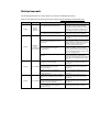
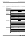
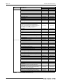
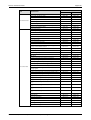
Related manuals
For detailed information on various devices also refer to the following manuals.
These can be obtained free of charge from our website at www.mitsubishi-automation.com.
Language
English
Device
Manual Name
Description
Simple
Motion
Module
MELSEC-L LD77MH Simple Motion Module This manual explains the functions of
User's Manual (Positioning Control)
Simple Motion Module type LD77MH.
In addition, it also describes the operations
of devices and parameters, what is a basic
knowledge necessary for programming.
MELSEC-L LD77MH Simple Motion Module This manual explains the functions of
User's Manual (Synchronous Control)
Simple Motion Module type LD77MH.
English
English
English
MELSEC-L Series Quick Start Guide
This quick start guide introduces the basic
installation procedures of programmable
controllers.
MELSEC-L CPU Module User's Manual
(Hardware Design, Maintenance and
Inspection)
Specifications of the CPU modules, power
supply modules, display unit, SD memory
cards, and batteries, information on how to
establish a system, maintenance and
inspection, and troubleshooting.
MELSEC-L
series
MELSEC-L CPU Module User's Manual
programmable (Function Explanation, Program
logic controller Fundamentals)
This manual explains the functions of CPU
modules. In addition, it also describes
devices and parameters, basic knowledge
necessary for programming, as well as the
operation of display units.
MELSEC System Q/L Series Programming
Manual
This manual describes the programming
and processing of the sequence and
application instructions that are provided
by the CPUs of the MELSEC System Q and L
series.
SSCNET III Compatible MR-J3-B Servo
Amplifier Instruction Manual
This manual explains I/O signals, parts
identification, parameters, and start-up
procedures.
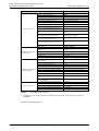
SSCNET III Compatible Linear Servo
Servo amplifier MR-J3-B-RJ004U Servo Amplifier
Instruction Manual
This manual explains I/O signals, parts
identification, parameters, and start-up
procedures.
SSCNET III interface 2-axis AC Servo
Amplifier MR-J3W-B Servo Amplifier
Instruction Manual
This manual explains I/O signals, parts
identification, parameters, and start-up
procedures.
SSCNET III/H interface AC Servo Amplifier
MR-J4-B Servo Amplifier Instruction Manual
This manual explains I/O signals, parts
identification, parameters, and start-up
procedures.
SSCNET III/H interface Multi-Axis AC Servo
Servo amplifier Amplifier MR-J4W2-B/MR-J4W3-B Servo
Amplifier Instruction Manual
General-Purpose AC Servo MELSERVO-J4
Servo Amplifier Instruction Manual
Trouble Shooting
This manual explains I/O signals, parts
identification, parameters, and start-up
procedures.
This manual gives an overview of all alarms
and warnings and explains remedies.
Safety guidelines
For use by qualified staff only
This manual is only intended for use by properly trained and qualified electrical technicians who are
fully acquainted with the relevant automation technology safety standards. All work with the hardware described, including system design, installation, configuration, maintenance, service and testing of the equipment, may only be performed by trained electrical technicians with approved qualifications who are fully acquainted with all the applicable automation technology safety standards
and regulations. Any operations or modifications to the hardware and/or software of our products
not specifically described in this manual may only be performed by authorised Mitsubishi Electric
staff.
Proper use of the products
The programmable controllers of the MELSEC-L series are only intended for the specific applications
explicitly described in this manual. All parameters and settings specified in this manual must be observed. The products described have all been designed, manufactured, tested and documented in
strict compliance with the relevant safety standards. Unqualified modification of the hardware or
software or failure to observe the warnings on the products and in this manual may result in serious
personal injury and/or damage to property. Only peripherals and expansion equipment specifically
recommended and approved by Mitsubishi Electric may be used with the programmable controllers
of the MELSEC-L series.
All and any other uses or application of the products shall be deemed to be improper.
Relevant safety regulations
All safety and accident prevention regulations relevant to your specific application must be observed
in the system design, installation, configuration, maintenance, servicing and testing of these products. The regulations listed below are particularly important in this regard.
This list does not claim to be complete; however, you are responsible for being familiar with and conforming to the regulations applicable to you in your location.
● VDE Standards
– VDE 0100
Regulations for the erection of power installations with rated voltages below 1000 V
– VDE 0105
Operation of power installations
– VDE 0113
Electrical installations with electronic equipment
– VDE 0160
Electronic equipment for use in power installations
– VDE 0550/0551
Regulations for transformers
– VDE 0700
Safety of electrical appliances for household use and similar applications
– VDE 0860
Safety regulations for mains-powered electronic appliances and their accessories for household use and similar applications.
● Fire safety regulations
● Accident prevention regulation
– VBG No. 4
Electrical systems and equipment
MELSEC-L Series, LD77MH Simple Motion Module Quick start guide
I
Safety warnings in this manual
In this manual special warnings that are important for the proper and safe use of the products are
clearly identified as follows:
II
m
DANGER:
b
CAUTION:
Personnel health and injury warnings.
Failure to observe the safety warnings identified with this symbol can result in health and injury
hazards for the user.
Equipment and property damage warnings.
Failure to observe the safety warnings identified with this symbol can result in damage to the
equipment or other property.
General safety information and precautions
The following safety precautions are intended as a general guideline for using PLC systems together
with other equipment. These precautions must always be observed in the design, installation and operation of all control systems.
m
DANGER:
● Observe all safety and accident prevention regulations applicable to your specific application. Always disconnect all power supplies before performing installation and wiring work
or opening any of the assemblies, components and devices.
● Assemblies, components and devices must always be installed in a shockproof housing fitted
with a proper cover and fuses or circuit breakers.
● Devices with a permanent connection to the mains power supply must be integrated in the
building installations with an all-pole disconnection switch and a suitable fuse.
● Check power cables and lines connected to the equipment regularly for breaks and insulation
damage. If cable damage is found immediately disconnect the equipment and the cables
from the power supply and replace the defective cabling.
● Before using the equipment for the first time check that the power supply rating matches that
of the local mains power.
● Take appropriate steps to ensure that cable damage or core breaks in the signal lines cannot
cause undefined states in the equipment.
● You are responsible for taking the necessary precautions to ensure that programs interrupted by brownouts and power failures can be restarted properly and safely. In particular, you
must ensure that dangerous conditions cannot occur under any circumstances, even for brief
periods. EMERGENCY OFF must be switched forcibly, if necessary.
● Residual current protective devices pursuant to DIN VDE Standard 0641 Parts 1-3 are not
adequate on their own as protection against indirect contact for installations with PLC
systems. Additional and/or other protection facilities are essential for such installations.
● EMERGENCY OFF facilities conforming to EN 60204/IEC 204 and VDE 0113 must remain fully
operative at all times and in all control system operating modes.The EMERGENCY OFF facility
reset function must be designed so that it cannot ever cause an uncontrolled or undefined
restart.
● You must implement both hardware and software safety precautions to prevent the possibility of undefined control system states caused by signal line cable or core breaks.
● When using modules always ensure that all electrical and mechanical specifications and
requirements are observed exactly.
● Do not install/remove the module or terminal block more than 50 times, after the first use of
the product (conforming to IEC 61131-2). Failure to do so may cause the module to malfunction due to poor contact of connector.
MELSEC-L Series, LD77MH Simple Motion Module Quick start guide
III
Precautions to prevent damages by electrostatic discharge
Electronic devices and modules can be damaged by electrostatic charge, which is conducted from the
human body to components of the controller. Always take the following precautions, when handling
the controller:
b
CAUTION:
● Before touching a module of the controller, always touch grounded metal, etc. to discharge
static electricity from human body.
● Wear isolating gloves when touching the powered controller, e. g. at maintenance during
visual check.
● You shouldn’t wear clothing made of synthetic fibre at low humidity. This clothing gets a very
high rate of electrostatic charge.
IV
Symbols used in the manual
Use of notes
Notes concerning important information are marked separately and are displayed as follows:
NOTE
Note text
Use of examples
Examples containing important information are clearly identified as follows:
Example
Example text
Use of numbering in the figures
Numbering within the figures is displayed by white numbers within black circles and is explained in
a table following it using the same number, e.g.:
Use of handling instructions
Handling instructions are steps that must be carried out in their exact sequence during startup, operation, maintenance and similar operations.
They are numbered consecutively (black numbers in white circles):
Text.
Text.
Text.
Use of footnotes in tables
Instructions in tables are explained in footnotes underneath the tables (in superscript). There is a footnote character at the appropriate position in the table (in superscript).
If there are several footnotes for one table then these are numbered consecutively underneath the table (black numbers in white circle, in superscript):
Text
Text
Text
Writing conventions and guidance notes
Keys or key-combinations are indicated in square brackets, such as [Enter], [Shift] or [Ctrl]. Menu
names of the menu bar, of the drop-down menus, options of a dialogue screen and buttons are indicated in italic bold letters, such as the drop down menu New in the Project menu or the option Serial USB in the "Transfer Setup Connection" screen.
MELSEC-L Series, LD77MH Simple Motion Module Quick start guide
V
VI
Contents
Contents
1
Overview
1.1
Features of Simple Motion Module (LD77MH) . . . . . . . . . . . . . . . . . . . . . . . . . . . . . . . . . . . . . . . . . . .1-1
2
Simple Motion Module start-up
2.1
Start-up procedure . . . . . . . . . . . . . . . . . . . . . . . . . . . . . . . . . . . . . . . . . . . . . . . . . . . . . . . . . . . . . . . . . . . . .2-2
2.2
System which combines LD77MH and MR-J3-B/MR-J4(W)-B. . . . . . . . . . . . . . . . . . . . . . . . . . . . . .2-3
2.3
Preparing devices . . . . . . . . . . . . . . . . . . . . . . . . . . . . . . . . . . . . . . . . . . . . . . . . . . . . . . . . . . . . . . . . . . . . . .2-4
2.4
Installing modules . . . . . . . . . . . . . . . . . . . . . . . . . . . . . . . . . . . . . . . . . . . . . . . . . . . . . . . . . . . . . . . . . . . . . .2-5
2.5
Wiring and connecting cables. . . . . . . . . . . . . . . . . . . . . . . . . . . . . . . . . . . . . . . . . . . . . . . . . . . . . . . . . . .2-6
2.6
Installing application software . . . . . . . . . . . . . . . . . . . . . . . . . . . . . . . . . . . . . . . . . . . . . . . . . . . . . . . . . .2-9
2.7
2.8
2.9
2.6.1
Installing MELSOFT GX Works2 . . . . . . . . . . . . . . . . . . . . . . . . . . . . . . . . . . . . . . . . . . . . . . . . .2-9
2.6.2
Installing MR Configurator2 . . . . . . . . . . . . . . . . . . . . . . . . . . . . . . . . . . . . . . . . . . . . . . . . . . . .2-9
2.6.3
Checking the start-up of MELSOFT GX Works2 . . . . . . . . . . . . . . . . . . . . . . . . . . . . . . . . 2-10
Creating sequence programs by using GX Works2 . . . . . . . . . . . . . . . . . . . . . . . . . . . . . . . . . . . . . 2-11
2.7.1
Creating a new project. . . . . . . . . . . . . . . . . . . . . . . . . . . . . . . . . . . . . . . . . . . . . . . . . . . . . . . 2-11
2.7.2
Creating sequence programs . . . . . . . . . . . . . . . . . . . . . . . . . . . . . . . . . . . . . . . . . . . . . . . . 2-12
2.7.3
Saving a sequence program as a project . . . . . . . . . . . . . . . . . . . . . . . . . . . . . . . . . . . . . . 2-13
2.7.4
Connecting CPU module and personal computer . . . . . . . . . . . . . . . . . . . . . . . . . . . . . 2-14
2.7.5
Formatting of the CPU module . . . . . . . . . . . . . . . . . . . . . . . . . . . . . . . . . . . . . . . . . . . . . . . 2-15
2.7.6
Writing the sequence program to the PLC CPU . . . . . . . . . . . . . . . . . . . . . . . . . . . . . . . 2-16
Creating parameter and positioning data by using Simple Motion Module Setting Tool. 2-17
2.8.1
Adding a Simple Motion Module . . . . . . . . . . . . . . . . . . . . . . . . . . . . . . . . . . . . . . . . . . . . . 2-17
2.8.2
Starting the Simple Motion Module Setting Tool . . . . . . . . . . . . . . . . . . . . . . . . . . . . . . 2-18
2.8.3
Creating a new project. . . . . . . . . . . . . . . . . . . . . . . . . . . . . . . . . . . . . . . . . . . . . . . . . . . . . . . 2-19
2.8.4
System setting. . . . . . . . . . . . . . . . . . . . . . . . . . . . . . . . . . . . . . . . . . . . . . . . . . . . . . . . . . . . . . . 2-20
2.8.5
Parameter setting . . . . . . . . . . . . . . . . . . . . . . . . . . . . . . . . . . . . . . . . . . . . . . . . . . . . . . . . . . . 2-21
2.8.6
Servo parameter setting . . . . . . . . . . . . . . . . . . . . . . . . . . . . . . . . . . . . . . . . . . . . . . . . . . . . . 2-25
2.8.7
Positioning data setting. . . . . . . . . . . . . . . . . . . . . . . . . . . . . . . . . . . . . . . . . . . . . . . . . . . . . . 2-26
2.8.8
Saving the Simple Motion Module as a project. . . . . . . . . . . . . . . . . . . . . . . . . . . . . . . . 2-28
2.8.9
Writing to the Simple Motion Module . . . . . . . . . . . . . . . . . . . . . . . . . . . . . . . . . . . . . . . . 2-29
2.8.10
Sample data for setting procedures . . . . . . . . . . . . . . . . . . . . . . . . . . . . . . . . . . . . . . . . . . 2-30
Operation check. . . . . . . . . . . . . . . . . . . . . . . . . . . . . . . . . . . . . . . . . . . . . . . . . . . . . . . . . . . . . . . . . . . . . . 2-31
2.9.1
JOG operation
(for checking the rotation direction, the electronic gear setting etc.). . . . . . . . . . . 2-31
2.9.2
OPR (for checking a home position) . . . . . . . . . . . . . . . . . . . . . . . . . . . . . . . . . . . . . . . . . . 2-36
2.9.3
Positioning control . . . . . . . . . . . . . . . . . . . . . . . . . . . . . . . . . . . . . . . . . . . . . . . . . . . . . . . . . . 2-38
MELSEC-L Series, LD77MH Simple Motion Module Quick start guide
VII
Contents
3
Synchronous control start-up
3.1
Start-up procedure in synchronous control . . . . . . . . . . . . . . . . . . . . . . . . . . . . . . . . . . . . . . . . . . . . . .3-3
3.2
2-axes system where synchronous control is available . . . . . . . . . . . . . . . . . . . . . . . . . . . . . . . . . . .3-4
3.3
Creating parameter for synchronous control . . . . . . . . . . . . . . . . . . . . . . . . . . . . . . . . . . . . . . . . . . . .3-5
3.4
System setting. . . . . . . . . . . . . . . . . . . . . . . . . . . . . . . . . . . . . . . . . . . . . . . . . . . . . . . . . . . . . . . . .3-5
3.3.2
Parameter and servo parameter settings . . . . . . . . . . . . . . . . . . . . . . . . . . . . . . . . . . . . . . .3-6
3.3.3
Positioning data setting. . . . . . . . . . . . . . . . . . . . . . . . . . . . . . . . . . . . . . . . . . . . . . . . . . . . . . . .3-7
3.3.4
Synchronous control parameter setting . . . . . . . . . . . . . . . . . . . . . . . . . . . . . . . . . . . . . . . .3-8
3.3.5
Cam data setting . . . . . . . . . . . . . . . . . . . . . . . . . . . . . . . . . . . . . . . . . . . . . . . . . . . . . . . . . . . . 3-11
Operation check of synchronous control . . . . . . . . . . . . . . . . . . . . . . . . . . . . . . . . . . . . . . . . . . . . . . 3-13
3.4.1
OPR (for establishing a home position) . . . . . . . . . . . . . . . . . . . . . . . . . . . . . . . . . . . . . . . 3-13
3.4.2
Start-up of drive axis . . . . . . . . . . . . . . . . . . . . . . . . . . . . . . . . . . . . . . . . . . . . . . . . . . . . . . . . . 3-14
3.4.3
Operation check of a synchronous axis . . . . . . . . . . . . . . . . . . . . . . . . . . . . . . . . . . . . . . . 3-15
3.4.4
Operation check with digital oscilloscope (check of cam operation) . . . . . . . . . . . 3-16
A
Appendix
A.1
Start address setting. . . . . . . . . . . . . . . . . . . . . . . . . . . . . . . . . . . . . . . . . . . . . . . . . . . . . . . . . . . . . . . . . . . A-1
A.2
A.3
A.4
VIII
3.3.1
A.1.1
Start address of Simple Motion Module. . . . . . . . . . . . . . . . . . . . . . . . . . . . . . . . . . . . . . . . A-1
A.1.2
Start address setting . . . . . . . . . . . . . . . . . . . . . . . . . . . . . . . . . . . . . . . . . . . . . . . . . . . . . . . . . . A-2
Parameter and positioning data. . . . . . . . . . . . . . . . . . . . . . . . . . . . . . . . . . . . . . . . . . . . . . . . . . . . . . . . A-3
A.2.1
Parameters . . . . . . . . . . . . . . . . . . . . . . . . . . . . . . . . . . . . . . . . . . . . . . . . . . . . . . . . . . . . . . . . . . . A-3
A.2.2
Positioning data . . . . . . . . . . . . . . . . . . . . . . . . . . . . . . . . . . . . . . . . . . . . . . . . . . . . . . . . . . . . . . A-5
Various monitor functions . . . . . . . . . . . . . . . . . . . . . . . . . . . . . . . . . . . . . . . . . . . . . . . . . . . . . . . . . . . . . A-6
A.3.1
Axis monitor. . . . . . . . . . . . . . . . . . . . . . . . . . . . . . . . . . . . . . . . . . . . . . . . . . . . . . . . . . . . . . . . . . A-6
A.3.2
Error history of Simple Motion Module Setting Tool . . . . . . . . . . . . . . . . . . . . . . . . . . . A-12
A.3.3
PLC diagnostics of GX Works2 . . . . . . . . . . . . . . . . . . . . . . . . . . . . . . . . . . . . . . . . . . . . . . . . A-13
Sample program . . . . . . . . . . . . . . . . . . . . . . . . . . . . . . . . . . . . . . . . . . . . . . . . . . . . . . . . . . . . . . . . . . . . . A-14
A.4.1
Used device list . . . . . . . . . . . . . . . . . . . . . . . . . . . . . . . . . . . . . . . . . . . . . . . . . . . . . . . . . . . . . . A-14
A.4.2
Sequence program example for synchronous control with 2 axes . . . . . . . . . . . . . A-15
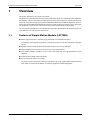
Features of Simple Motion Module (LD77MH)
1
Overview
Overview
This english document is the original instruction.
This quick start guide describes the items and the operations which are needed to wire the Simple Motion Module, as well as to perform the JOG operation, the program operation and the simultaneous
control by using the FA engineering software MELSOFT GX Works2 and MR Configurator2, for users
who use the Simple Motion Module for the first time. To fully utilize each module, such as CPU modules of MELSEC-L series, please refer to the relevant manuals depending on the purpose.
For users who use the MELSEC-L series CPU module (hereafter "CPU module") for the first time, please
read "MELSEC-L Series Quick Start Guide" once.
1.1
Features of Simple Motion Module (LD77MH)
● Wide range of controls is realised by high performance and multiple functions.
This module realises positioning control, synchronous control, cam control and speed and torque
control.
● Adoption of the built-in synchronous encoder interface realises cost reduction.
● Highly flexible baseless structure realises space-saving control board.
● This module supports SSCNET III and it can be connected with the high-performance servo
amplifier.
● Simple control setting, without programs.
● Assistant function realises easy setup.
Parameters can be setup, from settings to adjustment, by using "Simple Motion Module Setting
Tool" which is installed in GX Works2 as standard equipment or MR Configurator2.
MELSEC-L Series, LD77MH Simple Motion Module Quick start guide
1-1
Overview
1-2
Features of Simple Motion Module (LD77MH)
Simple Motion Module start-up
2
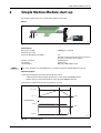
Simple Motion Module start-up
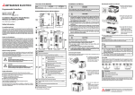
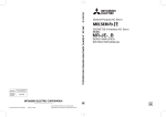
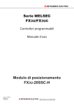
This chapter explains the 1-axis system which applies a ball screw.
Device
PB
I001001
Fig. 2-1:
1-axis system
Specifications
Ball screw lead (PB)
Reduction gear ratio
(Load side (NL)/Motor side (NM))
Encoder resolution
Servomotor
Servo amplifier
NOTE
: 10000.0 μm (= 10 mm)
: 1/2
(The ball screw on load side makes one rotation
for each 2 revolutions of the motor.)
: 262144 pls/rev
: HF-KP series
: MR-J3-B or MR-J4(W)-B series
The servo amplifier series MR-J4(W)-B has an encoder resolution of 4194304 pls/rev (22-bit).
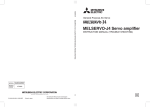
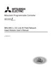
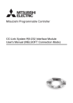
Operation pattern
햲 Reciprocate between the home position (0 mm) and P1.
– a) Move from the home position (0 mm) to P1 at the speed of 2000.00 mm/min.
– b) Move from P1 to the home position at the speed of 30000.00 mm/min.
햳 Execute the continuous positioning control to a) and b).
Position [mm]
P1 = 100.0
P0 = 0.0
Time
Speed [mm/min]
2000.00
Time
–30000.00
operation_1
Fig. 2-2:
Operation pattern
MELSEC-L Series, LD77MH Simple Motion Module Quick start guide
2-1
Simple Motion Module start-up
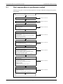
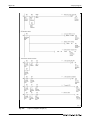
2.1
Start-up procedure
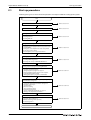
Start-up procedure
Following chart gives an overview of the operations and steps needed for starting up the system:
Start
System which combines LD77MH and MR-J3-B/MR-J4(W)-B
Refer to section 2.2
Preparing devices
Refer to section 2.3
Installing modules
앫 Installing modules
앫 Installing batteries
앫 Installing DIN rails
Refer to section 2.4
Wiring and connecting cables
앫 Wiring the power supply module
앫 Wiring the power supply and the motor power to the
servo amplifier
앫 Setting the servo amplifier axis select rotary switch
앫 Connecting various cables
앫 Checking if the power is properly turned on
Refer to section 2.5
Installing application software
앫 Installing MELSOFT GX Works2
앫 Installing MR Configurator2
앫 Checking the start-up of MELSOFT GX Works2
Refer to section 2.6
Creating sequence programs by using GX Works2
앫
앫
앫
앫
앫
앫
Creating a new project
Creating sequence programs
Saving a sequence program as a project
Connecting CPU module and personal computer
Formatting of the CPU module
Writing the sequence program to the PLC CPU
Refer to section 2.7
Creating parameter and positioning data by using Simple
Motion Module Setting Tool
앫
앫
앫
앫
앫
앫
앫
앫
앫
Adding a Simple Motion Module
Starting the Simple Motion Module Setting Tool
Creating a new project
System setting
Parameter setting
Servo parameter setting
Positioning data setting
Saving a Simple Motion Module as a project
Writing to the Simple Motion Module
Refer to section 2.8
Operation check
앫 JOG operation (for checking the rotation direction, the
electronic gear setting etc.)
앫 OPR (for checking a home position)
앫 Positioning control
End
2-2
Refer to section 2.9
System which combines LD77MH and MR-J3-B/MR-J4(W)-B
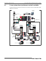
2.2
Simple Motion Module start-up
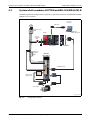
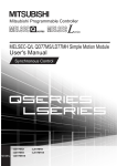
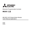
System which combines LD77MH and MR-J3-B/MR-J4(W)-B
The following shows the configuration example of a system which combines LD77MH4, MR-J3-B/MRJ4(W)-B and a servomotor.
Personal
computer
USB cable
∼
No-fuse breaker
(NFB)
GX Works2
MR Configurator2
L61P
Circuit
Protector
(CP)
CP
L26CPU-BT
Magnetic
contactor
(MC)
LD77MH4
MR-J3B/
MR-J3-B
MR-J4(W)-B
SSCNET III cable
Motor power
supply cable
Encoder cable
Servo motor
config_example_chap2
Fig. 2-3:
Configuration example
MELSEC-L Series, LD77MH Simple Motion Module Quick start guide
2-3
Simple Motion Module start-up
2.3
Preparing devices
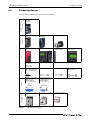
Preparing devices
Simple Motion Module
LD77MH4
LD77MH16
Servo amplifier
MR-J3-B
Servo amplifier
MR-J4(W)-B
Servomotor
Power supply module
L61P
CPU module
END cover L6EC (Included Display unit L6DSP
with CPU module)
(Optional)
DIN rail (JIS C 2812)
앫 TH35-7.5Fe
앫 TH35-7.5AI
앫 TH35-15Fe
DIN rail stopper
USB cable
MR-J3USBCBL3M (USB A
type – USB mini B type
Encoder cable
MELSOFT programming
tool GX Works2
SW1DNC-GXW2-E
Version 1.48A or later
Servo amplifier setup software MR Configurator2
SW1DNC-MRC2-E
Version 1.01B or later
No-fuse circuit breaker
(NFB)
Magnetic contactor (MC)
Motor power supply cable SSCNET III Cable
MR-J3BUS첸M
Power distribution
devices
Software
Cables
PLCs
Servo amplifier,
Servomotor
Simple Motion Module
Main unit
Please prepare the following devices, cables and software.
Tab. 2-1:
2-4
Devices to be prepared
Circuit protector (CP)
Installing modules
2.4
Simple Motion Module start-up
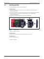
Installing modules
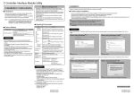
This section shows how to install the prepared modules.
Installing modules
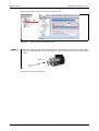
Release the module joint levers located on the top and bottom of the LD77MH module.
(Slide the hook forward.)
Engage the LD77MH module and the connector of the CPU module by plugging them properly.
Lock the module joint levers located on the top and bottom of the LD77MH module.
(Slide the hook backward.)
Follow the same procedures of steps to to install the END cover.
➡
➡
➡
➡
system_view_2
Fig. 2-4:
Installing modules
Installation of modules completed.
Installing batteries
Connect a battery connector when using the CPU module for the first time.
Installing DIN rails
Install the module to DIN rails.
Installation is completed.
MELSEC-L Series, LD77MH Simple Motion Module Quick start guide
2-5
Simple Motion Module start-up
2.5
Wiring and connecting cables
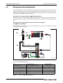
Wiring and connecting cables
The following shows the connection examples of wiring and connecting cables of the Simple Motion
Module (LD77MH) and the servo amplifier (MR-J3/MR-J4 series). Use cables with the same wire size as
when the servo amplifier MR-J3-10B is used. In case that the capacity of the servo amplifier is different,
refer to the servo amplifier instruction manuals.
Wiring the power supply module (part of the figure below)
The following shows an example of wiring the power supply wires and grounding wire tor power supply module. Connect an isolation transformer when much noise is generated in the power supply system.
Wiring the power supply and the motor power to the servo amplifier
(part of the figure below)
Wire the control circuit power (L11, L21), main circuit power (L1, L2 and L3) and motor power line (U,
V and W) to the servo amplifier.
∼
Circuit
Protector
(CP)
CP
AWG14
Grounding
Grounding
AWG14
L1
L2
L3
AWG16
L11
L21
AWG16
AWG16
Grounding
block_diagram_3_interim
Fig. 2-5:
Wiring example
Wire sizes and tightening torques:
Item
Applicable wire size
Tightening torque
Power supply wires
0.75 to 2 mm (AWG18 to AWG14)
0.59 to 0.88 Nm
Grounding wire 0.75 to 2 mm2 (AWG18 to AWG14)
0.59 to 0.88 Nm
Control circuit power (L11, L21)
2
1.25 mm (AWG16)
2
—
Main circuit power (L1, L2, L3)
2 mm (AWG14)
—
Motor power line (U, V, W)
1.25 mm2 (AWG16)
—
Grounding wire 1.25 mm2 (AWG16)
1.2 Nm
Tab. 2-2:
2-6
2
Wire sizes and tightening torques
Wiring and connecting cables
Simple Motion Module start-up
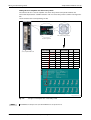
Setting the servo amplifier axis select rotary switch
The switches "0" to "F" of servo amplifier axis select rotary switch correspond to d01 to d16.
The relationship between "SSCNET Structure" and axis select rotary switch is shown in the figure below.
Set the switches to the corresponding axis No.
Axis select rotary switch
Cover is opened
Servo amplifier MR-J3-B
Axis select
rotary switch
d첸첸
Axis no.
Axis select
rotary switch
d첸첸
Axis no.
"0"
d01
1
"8"
d09
9
"1"
d02
2
"9"
d10
10
"2"
d03
3
"A"
d11
11
"3"
d04
4
"B"
d12
12
"4"
d05
5
"C"
d13
13
"5"
d06
6
"D"
d14
14
"6"
d07
7
"E"
d15
15
"7"
d08
8
"F"
d16
16
Refer to section 2.8 for details of system setting.
rotary_switch, screen_001
Fig. 2-6:
NOTE
Setting of servo amplifier axis select rotary switch
LD77MH4 can set up to axis 4, and LD77MH16 can set up to axis 16.
MELSEC-L Series, LD77MH Simple Motion Module Quick start guide
2-7
Simple Motion Module start-up
Wiring and connecting cables
Connecting various cables
Connect the SSCNET III cable and the encoder cable. Connect the USB cable between personal computer and PLC CPU. (Refer to section 2.2)
Checking if the power is properly turned on
Make sure that the power supply of PLC and servo amplifier is properly turned on.
Check the wiring of the PLC CPU module.
Turn on the power supply of the PLC.
Power supply module:
LED (Green) is lit
CPU module:
MODE LED (Green) is lit
system_view_3
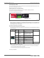
Fig. 2-7:
Status of LEDs after turning on the power supply
When parameters and programs are not written to the CPU module, there is no problem with
flashing of ERR LED in red. ERR LED is turned off when the power supply is turned off and then on
after writing parameters and programs.
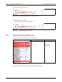
Check the wiring of the servo amplifier.
Turn on the power supply of the servo amplifier.
The communication status with LD77MH can be checked in the servo amplifier display according
to the table below.
Servo amplifier
display
LED
display
Status
Description
AA Initializing standby
The power supply of the LD77MH is
turned off.
Ab Initializing
The power supply of the servo
amplifier is turned on while the
power supply of the LD77MH is
turned off.
b01
Ready OFF
PLC ready signals of LD77MH are
received.
C01
Servo OFF
Servo off command is received.
d01
Servo ON
All axes servo on signal of LD77MH
received.
E6
During servo forced During servo forced stop of the
stop
servo amplifier
E7
During controller
force stop
During force stop of LD77MH
—
The control power supply is turned
off.
Off Wiring result
Normal
Normal
Error
Tab. 2-3: Check of communication status
The LED display of the servo amplifier is AA or Ab when parameters are not written to LD77MH, but
there is no problem. Write parameters to LD77MH.
Check the wiring of the control power supply when LED is turned off.
The wiring is completed.
2-8
Installing application software
2.6
Simple Motion Module start-up
Installing application software
The following shows how to install MELSOFT GX Works2 as a programming tool, and MR
Configurator2 as a servo parameter setting tool.
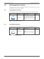
2.6.1
Installing MELSOFT GX Works2
Install the software by following the instruction manual which comes with MELSOFT GX Works2.
Item
Supported
version
Model name
Function overview
SW1DNC-GXW2-E
Mitsubishi IQ Platform-compatible Programmable Controller Engineering Software
(Integrated software of programming, simu- 1.48A
lation, module settings and monitoring tool
function)
MELSOFT GX Works2
Tab. 2-4:
2.6.2
Software MELSOFT GX Works2
Installing MR Configurator2
Please contact your nearest Mitsubishi sales representative for the MR Configurator2.
Item
Supported
version
Model name
Function overview
SW1DNC-MRC2-E
Parameter settings and adjustment of servo
amplifier
1.01B or later
(Parameter settings, monitoring and graphs)
MR Configurator2
Tab. 2-5:
Software MR Configurator2
MELSEC-L Series, LD77MH Simple Motion Module Quick start guide
2-9
Simple Motion Module start-up
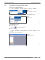
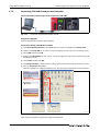
2.6.3
Installing application software
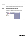
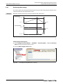
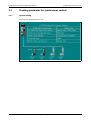
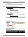
Checking the start-up of MELSOFT GX Works2
Creating an icon of MELSOFT GX Works2
Select Start All Programs MELSOFT Application GX Works2 GX Works2.
Fig. 2-8:
Selecting the program GX Works2
screen_002/003
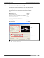
Create the icon by right-clicking to select Send To Desktop (create shortcut).
Fig. 2-9:
Creating an icon
screen_004
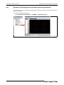
Starting MELSOFT GX Works2
● When there is an icon
Double-click
to start MELSOFT GX Works2.
● When there is no icon
Select Start All Programs MELSOFT Application GX Works2 GX Works2 to start the
software.
The main screen of GX Works2 will appear.
Fig. 2-10:
GX Works2 main screen
screen_005
2 - 10
Creating sequence programs by using GX Works2
2.7
Simple Motion Module start-up
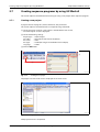
Creating sequence programs by using GX Works2
This section explains the methods from creating to saving a new project of the sequence program.
2.7.1
Creating a new project
A project consists of programs, device comments, and parameters.
This section explains the method with an example of using L26CPU-BT.
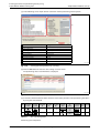
Select the icon for creating a new project in the GX Works2 main screen.
The "New Project" screen is displayed.
Select the following settings:
Project Type
Use Label
PLC Series
PLC Type
Language
: Simple Project
: Not used (do not click the checkbox)
: LCPU
: L26-BT (for using the L26CPU-BT in this example)
: Ladder
Click the OK button.
screen_007E
Fig. 2-11:
Creating a new project
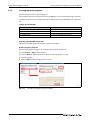
The project tree and circuit screen is displayed on the main screen.
screen_008
Fig. 2-12:
Project tree and circuit screen
New project creation is completed.
MELSEC-L Series, LD77MH Simple Motion Module Quick start guide
2 - 11
Simple Motion Module start-up
2.7.2
Creating sequence programs by using GX Works2
Creating sequence programs
For the next step, create a sequence program.
For the details, refer to the related manuals for the MELSEC-L series programmable logic controller.
In addition, if you wish to use sample data, please contact your nearest Mitsubishi sales representative.
Sample data of LD77MH
Project name
Description
L02_LD77MH4_SEQ
for L02CPU and LD77MH4 (Axis 4 type)
L26_LD77MH4_SEQ
for L26CPU and LD77MH4 (Axis 4 type)
L02_LD77MH16_SEQ
for L02CPU and LD77MH16 (Axis 16 type)
L26_LD77MH16_SEQ
for L26CPU and LD77MH16 (Axis 16 type)
Tab. 2-6:
LD77MH sample data for creating sequence programs
Unpacking the LD77MH sample data
Unpack the LD77MH sample data (ld77mhe_00c) into any folder.
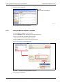
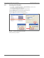
Reading sequence programs
Projects of the sequence program are read from the unpacked sample data.
Select Project Open... from the menu.
Click the Browse... button to select the folder in which the project is saved.
Select the project.
Click the Open button to display the main screen.
screen_08E
Fig. 2-13:
2 - 12
Procedure of reading a sequence program
Creating sequence programs by using GX Works2
Simple Motion Module start-up
The main screen is displayed.
Fig. 2-14:
Main screen for selected project
screen_011
Reading of sequence program completed.
2.7.3
Saving a sequence program as a project
Select Project Save As... from the menu.
Click the Browse... button to specify the save destination path.
Enter any names (for workspace, project and title).
Make sure not to overwrite the original project.
Click the Save button. A confirmation message appears.
To save the project, click the Yes button.
screen_009E
Fig. 2-15:
Procedure of saving a program as a project
Saving project is completed.
MELSEC-L Series, LD77MH Simple Motion Module Quick start guide
2 - 13
Simple Motion Module start-up
2.7.4
Creating sequence programs by using GX Works2
Connecting CPU module and personal computer
Connect the CPU module and personal computer via USB cable
connection_PC_system
Fig. 2-16:
Connection of PC and CPU module via USB
PLC power supply ON
Turn on the power of the power supply module.
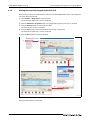
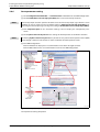
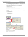
Connection settings of GX Works2 and PLC
Click Connection Destination in the GX Works2 main screen and double-click Connection1.
Double-click Serial USB on "PC side I/F" section to display the "PC side I/F Serial Setting" screen.
Select USB. Confirm with OK.
Double-click CPU Module on "PLC side I/F" section to display the "PLC side I/F Detailed Setting of
PLC Module" screen.
Select LCPU. Confirm with OK.
Click No Specification in "Other Stations Setting" section of "Transfer Setup Connection1" screen.
Click the Connection Test button.
When the procedure is completed without error, the connection completion screen will appear.
screen_011E
Fig. 2-17:
Connection settings
Connecting CPU module and personal computer completed.
2 - 14
Creating sequence programs by using GX Works2
2.7.5
Simple Motion Module start-up
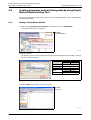
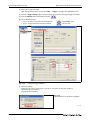
Formatting of the CPU module
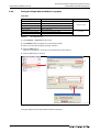
Select Online PLC Memory Operation Format PLC Memory... from the menu.
The "Format PLC Memory" screen is displayed.
Select Program memory/Device memory from "Target memory".
Click the Execute button to start the memory formatting process.
Click the Yes button to confirm memory formatting.
Click the OK button to confirm the completion message.
screen_012E
Fig. 2-18:
Procedure of formatting the CPU module
Memory formatting is completed.
MELSEC-L Series, LD77MH Simple Motion Module Quick start guide
2 - 15
Simple Motion Module start-up
2.7.6
Creating sequence programs by using GX Works2
Writing the sequence program to the PLC CPU
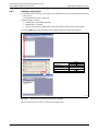
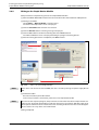
Open the front side cover of CPU module, and move the RESET/RUN/STOP switch to the STOP position. Then, write data to CPU.
Select Online Write to PLC... from the menu.
The "Online Data Operation" screen is displayed.
Click the Parameter + Program button. The corresponding targets in the list are selected.
Click the Execute button to write to the PLC CPU.
The "Write to PLC" screen is displayed.
Click the Close button to close the window after writing is completed.
The "Online Data Operation" screen is displayed.
Click the Close button to close the window.
screen_014E
Fig. 2-19:
Procedure of writing the sequence program to the PLC CPU
Writing to CPU module is completed.
2 - 16
Creating parameter and positioning data by using
Simple Motion Module Setting Tool
2.8
Simple Motion Module start-up
Creating parameter and positioning data by using Simple
Motion Module Setting Tool
This section explains the setting methods of parameters and positioning data used in the Simple Motion Module (LD77MH).
2.8.1
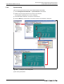
Adding a Simple Motion Module
Right-click on Intelligent Function Module in GX Works2 and select New Module....
The "New Module" screen is displayed.
Fig. 2-20:
Select New Module
screen_015E
Select a module.
The following shows a setting example of when the Simple Motion Module (LD77MH) is connected next to the CPU module.
Item
Module Type
PLC type
L02CPU
L26CPU-BT
Simple Motion Module
Module Name
Mounted Slot No.
LD77MH4
0
Specify start XY
address
(Click the checkbox)
Title
0010
0030
Optional
screen_029E
Fig. 2-21:
Setting example
Click the OK button to return to the main screen.
Fig. 2-22:
Main screen
screen_030J
MELSEC-L Series, LD77MH Simple Motion Module Quick start guide
2 - 17
Creating parameter and positioning data by using
Simple Motion Module Setting Tool
Simple Motion Module start-up
NOTE
The start address of the Simple Motion Module (LD77MH) differs depending on the combination
with CPU module. For details, refer to section A.1 "Start address setting".
Setting is completed.
The following explains the setting method with the Simple Motion Module Setting Tool.
2.8.2
Starting the Simple Motion Module Setting Tool
Select Intelligent Function Module LD77MH4 Simple Motion Module in GX Works2 to start
the Simple Motion Module Setting Tool.
The "MELSOFT Series Simple Motion Module Setting Tool" screen is displayed.
screen_016E
Fig. 2-23:
2 - 18
Start the Simple Motion Module Setting Tool
Creating parameter and positioning data by using
Simple Motion Module Setting Tool
2.8.3
Simple Motion Module start-up
Creating a new project
Select the icon for creating a new project in the "MELSOFT Series Simple Motion Module Setting
Tool" screen.
The "New Module" screen is displayed.
Make settings as follows:
앫 Module Type: Simple Motion Module
앫 Module Name: LD77MH4
앫 Specify start XY address: 0030 (differs according to the PLC type used, see table below)
Click the OK button to add LD77MH to the intelligent function module of the project.
Item
Module Type
Module Name
Specify start XY address
Title
PLC type
L02CPU
L26CPU-BT
Simple Motion Module
LD77MH4
0010
0030
Optional
screen_017E
Fig. 2-24:
Procedure of creating a new project via setting tool
Continue with the next section to set the system configuration.
MELSEC-L Series, LD77MH Simple Motion Module Quick start guide
2 - 19
Creating parameter and positioning data by using
Simple Motion Module Setting Tool
Simple Motion Module start-up
2.8.4
System setting
Set the necessary parameters for the Simple Motion Module (LD77MH).
Select Intelligent Function Module System Structure in GX Works2.
Double-click the image of the first axis of the servo amplifier.
The "Amplifier Setting [Axis #1]" screen is displayed.
Select MR-J3(W)-B. If MR-J4 is used please select MR-J3-B
Click the OK button. The previous screen with selected servo amplifier is displayed.
screen_018E
Fig. 2-25:
Setting the system configuration
System setting completed.
2 - 20
Creating parameter and positioning data by using
Simple Motion Module Setting Tool
2.8.5
Simple Motion Module start-up
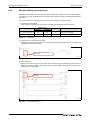
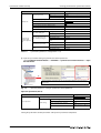
Parameter setting
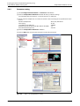
Select Intelligent Function Module Parameter in GX Works2.
Click the Compute Basic Parameter 1 button for basic parameter settings.
The "Compute Basic Parameters 1" screen for Axis No. 1 is displayed.
Select machine components and enter the machine data according to the specification of the
device:
Machine Components
: Ball Screw, Horizontal
Unit Setting
: 0: mm
Lead of Ball Screw (PB) [μm]
: 10000.0
Reduction Gear Ratio (Load side (NL)/ Motor side (NM)) : 1/2
Encoder Resolution [pls/rev]
: 262144
Click the Compute Basic Parameters 1 button.
Click the OK button to reflect the calculation result to the parameter.
screen_019E
Fig. 2-26:
Steps to of parameter setting
MELSEC-L Series, LD77MH Simple Motion Module Quick start guide
2 - 21
Creating parameter and positioning data by using
Simple Motion Module Setting Tool
Simple Motion Module start-up
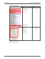
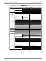
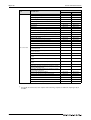
Set other parameters.
Change the underlined part. (There is no need to change the basic parameter 1 since the
parameter is already set in the previous section.)
The value can be changed by double-clicking each item of the parameter setting screen.
NOTES
The default values of the input signal logic selection upper limit and lower limit are set to negative
logic, considering the safety. If you do not use these signals, change the values to positive logic
before use.
Forced stop input signal is enabled, considering the safety. If users do not use this signal, switch it
to be disabled before using.
Item
Description
Basic parameters 1
Basic parameters 2
Detailed parameters 1
Detailed parameters 2
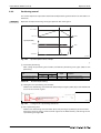
Tab. 2-7:
2 - 22
Unit setting
0: mm
Number of pulses per revolution
16384 pls/rev (262144 pls/rev)
Movement amount per revolution
312.5 μm (5000.0 μm)
Unit magnification
1: × 1 time
Bias speed at start
0.00 mm/min
Speed limit value
30000.00 mm/min
Acceleration time 0
1000 ms
Deceleration time 0
1000 ms
Backlash compensation amount
0.0 μm
Software stroke limit upper limit value
214748364.7 μm
Software stroke limit lower limit value
-214748364.8 μm
Software stroke limit selection
0: Apply Software Limit to Current Feed Value
Software stroke limit valid/invalid setting
0: Valid
Command in-position width
10.0 μm
Torque limit setting value
300 %
M code ON signal output timing
0: WITH mode
Speed switching mode
0: Standard Speed Switching Mode
Interpolation speed designation method
0: Composite Speed
Current feed value during speed control
0: Not update of current feed value
Input signal logic selection : lower limit
1: Positive Logic
Input signal logic selection : upper limit
1: Positive Logic
Input signal logic selection : Stop signal
0: Negative Logic
Input signal logic selection: External command/ switching signal 0: Negative Logic
Input signal logic selection: Near-point dog
signal
0: Negative Logic
Input signal logic selection: Manual pulse
generator input
0: Negative Logic
External Input signal selection
1: Use Input of Servo Amplifier
Manual pulse generator/ Incremental synchronous encoder input selection
0: A-phase/B-phase mode (4 multiply)
Speed-position function selection
0: Speed-Position Switching Control (INC
Mode)
Forced stop valid/invalid selection
1: Invalid
Acceleration time 1
1000 ms
Acceleration time 2
1000 ms
Acceleration time 3
1000 ms
Deceleration time 1
1000 ms
Deceleration time 2
1000 ms
Deceleration time 3
1000 ms
JOG speed limit value
15000.00 mm/min
JOG operation acceleration time selection
0: 1000
JOG operation deceleration time selection
0: 1000
Acceleration/deceleration process selection
0: Trapezoidal acceleration/ deceleration
processing
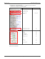
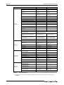
Other parameters setting (1)
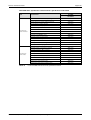
Creating parameter and positioning data by using
Simple Motion Module Setting Tool
Item
Simple Motion Module start-up
Description
S-curve ratio
Detailed parameters 2
OPR (Original Point Return)
Basic parameters
100 %
Sudden stop deceleration time
1000 ms
Stop group 1 sudden stop selection
0: Normal deceleration stop
Stop group 2 sudden stop selection
0: Normal deceleration stop
Stop group 3 sudden stop selection
0: Normal deceleration stop
Positioning complete signal output time
300
Allowable circular interpolation error width
10.0 μm
External command function selection
0: External positioning start
Speed control 10 x multiplier setting for
degree axis
0: Invalid
Restart allowable range when servo OFF to
ON
0 pls/rev
Manual pulse generator/ Incremental synchronous encoder input type selection
0: Differential output type
Operation setting for speed-torque control
mode: Speed initial value selection
0: Command speed
Operation setting for speed-torque control
mode: Condition selection at mode switching
0: Switching Conditions Valid at Switching
Mode
External command signal selection 0: Unused
OPR method
6: Data set method
OPR direction
0: Positive direction (address increment
direction)
OP address
0.0 μm
OPR speed
0.01 mm/min
Creep speed
0.01 mm/min
OPR retry
0: Do not retry OPR with limit switch
Setting for the movement amount after near- 0.0 μm
point dog ON
OPR acceleration time selection
OPR (Original Point Return)
Detailed parameters
Expansion parameters
Tab. 2-7:
0: 1000
OPR deceleration time selection
0: 1000
OP shift amount
0.0 μm
OPR torque limit value
300 %
Operation setting of incompletion of OPR
0: Positioning control is not executed.
Speed designation during OP shift
0: OPR speed
Dwell time during OPR retry
0 ms
Pulse conversion module: OPR request setting
0: Turn OPR Request ON at Servo OFF
Pulse conversion module: Waiting time after
clear signal output
100 ms
Optional data monitor: Data type setting 1
0: No Setting
Optional data monitor: Data type setting 2
0: No Setting
Optional data monitor: Data type setting 3
0: No Setting
Optional data monitor: Data type setting 4
0: No Setting
Operation cycle setting 1: 1.77 ms
Other parameters setting (2)
The Operation cycle setting and External command signal selection are used only in a parameter of
LD77MH16.
Parameter setting completed.
MELSEC-L Series, LD77MH Simple Motion Module Quick start guide
2 - 23
Creating parameter and positioning data by using
Simple Motion Module Setting Tool
Simple Motion Module start-up
Example
Setting the speed limit value in maximum motor speed
Ball screw lead
Servomotor
Gear ratio
Speed limit value
:
:
:
=
=
=
10.0 mm
HF-KP13 (262144 pls/rev)
1/2
Maximum motor speed × Gear ratio × Ball screw lead
6000 r/min × 1/2 × 10 mm
30000.00 mm/min
2 - 24
Creating parameter and positioning data by using
Simple Motion Module Setting Tool
2.8.6
Simple Motion Module start-up
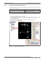
Servo parameter setting
Select Intelligent Function Module Servo Parameter in GX Works2 to start MR Configurator2.
Select Invalid (Not use forced stop input (EM1)) of the "Servo forced stop selection".
NOTE
Forced stop input selection specifies whether to use the forced stop input signal from the servo
amplifier or not. For safety reasons, the default setting is Valid (Use forced stop input (EM1)). For
not using the forced input signal, change the setting to Invalid (Not use forced stop input (EM1)).
Click Component parts in the "Parameter Setting" screen to display the "Component parts"
screen.
Select Z-phase must not be passed in the settings of "Home position set condition selection".
NOTE
If selecting Z-phase must not be passed, it is possible to carry out the home position return (OPR)
even though a motor has not turned 1 or more revolutions for home position return.
Close MR Configurator2:
Click the x button to display the save confirmation screen of the changed contents.
Click the Yes button on the save confirmation screen to close MR Configurator2.
screen_020E
Fig. 2-27:
Steps to of servo parameter setting
Servo parameter setting completed
MELSEC-L Series, LD77MH Simple Motion Module Quick start guide
2 - 25
Creating parameter and positioning data by using
Simple Motion Module Setting Tool
Simple Motion Module start-up
2.8.7
Positioning data setting
This section explains the setting method of the positioning data with using program examples which
reciprocate between the home position and P1.
Example
Operation example of returning the original position after moving to P1
Position [mm]
P1 = 100.0
P0 = 0.0
Time
Speed [mm/min]
2000.00
Time
–30000.00
operation_1
Fig. 2-28:
Operation pattern of the example
Selecting the positioning data
Select Intelligent Function Module LD77MH4 Positioning Data Axis #1 Positioning
Data to display the positioning data screen.
Click the Data Setting Assistant button.
screen_021E
Fig. 2-29:
2 - 26
Selecting positioning data (steps and )
Creating parameter and positioning data by using
Simple Motion Module Setting Tool
Simple Motion Module start-up
In the following screen input data for each item and the positioning control system.
Item
Positioning control selection
Positioning Data No.
Positioning Address (Reference axis)
Command Speed
Operation Pattern
Acceleration Time No.
Deceleration Time No.
Dwell Time
M code
Setting value
1-axis linear control (ABS)
1
100000.0 μm
2000.00 mm/min
Continuation
0: 1000
0: 1000
0: 0 ms
0
screen_022E
Fig. 2-30:
Selecting positioning data (steps and )
Click the Set button to close the data setting assistant screen.
The positioning data screen with data is displayed.
screen_023E
Fig. 2-31:
Positioning data screen with set data
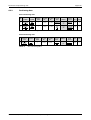
Create the command which returns from P1 to the home position in the positioning data No. 2
by using the same method.
No.
1
2
Operation
pattern
1:
Continuation
0:
Completion
Tab. 2-8:
Control
system
Axis to be Accelerainterpolat- tion time
ed
No.
Deceleration time
No.
Positioning address
Arc
address
Command Dwell
speed
time M code
ABS
linear 1
—
1: 1000
1: 1000
100000.0
μm
0.0
μm
2000.00
mm/min
0 ms
0
ABS
linear 1
—
1: 1000
1: 1000
0.0
μm
0.0
μm
30000.00
mm/min
0 ms
0
Axis 1 positioning data
Positioning data completed.
MELSEC-L Series, LD77MH Simple Motion Module Quick start guide
2 - 27
Creating parameter and positioning data by using
Simple Motion Module Setting Tool
Simple Motion Module start-up
2.8.8
Saving the Simple Motion Module as a project
Save data
Item
Description
System Structure
Existence of axes, amplifiers and virtual servo to be used
Remark
Parameter
Overall parameter of each axis
Servo parameter
Parameter of servo amplifier
Positioning data
Positioning data
Block start data
Data for block start
Synchronous control parameter
Parameter for synchronous control
Cam data
Cam pattern
Tab. 2-9:
Always necessary
If needed
Save data overview
Select Project Save As from the menu.
Click Browse button to specify the save destination path.
Enter any names (for workspace, project and title).
Click the Save button.
When the new project is saved, the save confirmation screen appears.
Click the Yes button to confirm.
screen_024E
Fig. 2-32:
Procedure of saving a project
Saving the project of the Simple Motion Module completed.
2 - 28
Creating parameter and positioning data by using
Simple Motion Module Setting Tool
2.8.9
Simple Motion Module start-up
Writing to the Simple Motion Module
Write parameters and positioning data to the Simple Motion Module.
Move the RESET/RUN/STOP switch on the front side of the PLC CPU module to STOP position.
Writing to LD77MH:
Select Online Write to Module... from the menu.
The "Online Data Operation" screen is displayed.
Click the Select All button. All items are selected.
Click the Execute button. A warning message is displayed.
Click the Yes button to confirm overwriting of the flash ROM contents.
The "Write to Module" screen is displayed showing the progress of writing process.
After the writing procedure is completed, click Close to finish.
screen_025E
Fig. 2-33:
NOTE
Steps to of writing procedure
If the data is not written to the flash ROM, the data is erased by turning the power supply OFF to
ON.
Power OFF to ON
Reset the PLC CPU or power OFF to ON.
If the servo parameter is overwritten, power the servo amplifier OFF to ON.
NOTE
Please write the sequence program, the parameters and the other data of the simple motion controller at first. And switch power off once and then switch it on again. When “ERR. LED” lights up or
blinks please confirm the error and take measures according to the manual. Please refer to Appendix A.2 and A.3 for a way of the error confirmation.
Writing completed.
MELSEC-L Series, LD77MH Simple Motion Module Quick start guide
2 - 29
Creating parameter and positioning data by using
Simple Motion Module Setting Tool
Simple Motion Module start-up
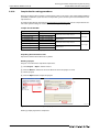
2.8.10
Sample data for setting procedures
Refer to the project of parameters and positioning data to be used in the Simple Motion Module
(LD77MH). In addition, if you wish to use sample data , please contact your nearest Mitsubishi sales
representative.
The projects provided on the website www.mitsubishi-automation.com contain sample data for section 2.8.4 "System setting" to section 2.8.7 "Positioning data setting".
Sample data of LD77MH
Project name
Description
L02_LD77MH4_POS
for L02CPU and LD77MH4
L26_LD77MH4_POS
for L26CPU and LD77MH4
L02_LD77MH4_SYNC
for L02CPU and LD77MH4
L26_LD77MH4_SYNC
for L26CPU and LD77MH4
L02-LD77MH16_POS
for L02CPU and LD77MH16
L26-LD77MH16_POS
for L26CPU and LD77MH16
L02-LD77MH16_SYNC
for L02CPU and LD77MH16
L26-LD77MH16_SYNC
for L26CPU and LD77MH16
Tab. 2-10:
Remark
Sample data of the simple motion
4-axis type
Sample data for synchronous control of the
simple motion
Sample data of the simple motion
16-axis type
Sample data for synchronous control of the
simple motion
LD77MH sample project data
Unpacking the download module
Unpack the download module into any folder.
Reading a project
Projects are read from the unpacked sample data.
Select Project Open... from the menu.
Click the Browse... button to select the folder in which the project is saved.
Select a project.
Click the Open button to open the project.
screen_006E
Fig. 2-34:
Procedure of reading sample project data
Reading sample project data completed.
2 - 30
Operation check
2.9
Simple Motion Module start-up
Operation check
This sequence program is an example using LD77MH4 and L26CPU-BT. When other modules are used,
the assignment of the signal is different. Please refer to the User's Manual (positioning control) for details of each signal.
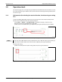
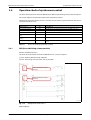
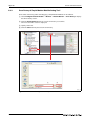
2.9.1
JOG operation (for checking the rotation direction, the electronic gear setting
etc.)
Move the RESET/RUN/STOP switch on the front side of the PLC CPU module to RUN position.
Turn the Servo ON device from the sequence program:
Select Online Monitor Start Monitoring in GX Works2 to display a monitor screen.
Move the cursor to the "PLC READY ON" signal (X7B).
Double-click the "PLC READY ON" signal (X7B) with pressing the [SHIFT] key to turn X7B ON.
Double-click with pressing the
[SHIFT] key.
screen_026E
Fig. 2-35:
NOTE
Turn the Servo ON device from the sequence program
To turn the device ON, double-click the specified device that is OFF with pressing the [SHIFT] key.
To turn the device OFF, double-click the device that is ON with pressing the [SHIFT] key.
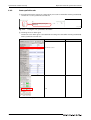
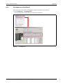
JOG speed setting:
Double-click "JOG operation speed setting" (X5D) with pressing the [SHIFT] key.
screen_027E
Fig. 2-36:
JOG speed setting
MELSEC-L Series, LD77MH Simple Motion Module Quick start guide
2 - 31
Simple Motion Module start-up
Operation check
JOG starting:
Double-click "Forward run JOG" (X5E) with pressing the [SHIFT] key to turn X5E ON and the axis
1 rotates forward.
Furthermore, double-click "Forward run JOG" (X5E) with pressing the [SHIFT] key to turn X5E OFF
and the axis 1 stops.
screen_028E
Fig. 2-37:
JOG starting
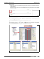
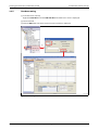
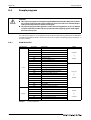
Checking JOG operation:
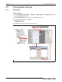
Select Intelligent Function Module Monitor Module Monitor Axis Monitor to display
the axis monitor initial window.
Click Select Monitor Axis to display the "Select Monitor Axis" screen.
Select Monitor Axis: Axis #1. After selection, click OK to return to the axis monitor initial window.
Click Select Monitor Item to display the "Select Monitor Item" screen.
screen_029E
Fig. 2-38:
2 - 32
Checking JOG operation
Operation check
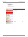
Simple Motion Module start-up
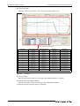
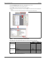
Select Monitor Items:
앫
앫
앫
앫
앫
앫
Forward JOG start, Reverse JOG start
Status: OPR request flag
Status: OPR complete flag
Start complete
External input signal: Lower limit
External input signal: Upper limit
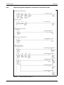
Axis Monitor
Screen
Check Item
Axis 1 Current feed value
—
Axis 1 Machine feed value
—
Axis operation status
Axis feed rate
Tab. 2-11:
Value
JOG Operation
100.00
Forward JOG start
ON
Reverse JOG start
OFF
Axis monitor (1)
MELSEC-L Series, LD77MH Simple Motion Module Quick start guide
2 - 33
Simple Motion Module start-up
Operation check
Screen
Check Item
Value
PLC READY
ON
LD77 READY
ON
Synchronization flag
ON
All axes servo ON
ON
Servo status : READY ON
Axis 1
Servo status : Servo ON
Axis 1
BUSY
Axis 1
Tab. 2-11:
ON
ON
Axis monitor (2)
Item
Operation
Status
All axes servo ON
Turn X7B ON.
Check servo amplifier LED.
Check the signal state of LD77 READY X30, Synchronization flag, PLC
READY and All axis servo.
Axis 1 JOG speed setting
Turn X5D ON.
Check the JOG speed at the axis 1 current feed speed.
Axis 1 forward rotation command turns ON
Turn X5E ON.
Check if the servomotor rotates forward. Check if the axis 1 current
feed value increases.
Axis 1 forward rotation command turns OFF
Turn X5E OFF.
Check if the servomotor stops.
Axis 1 reverse rotation command turns ON
Turn X5F ON.
Check if the servomotor rotates reversely. Check if the axis 1 current
feed value decreases.
Axis 1 reverse rotation command turns OFF
Turn X5F OFF.
Check if the servomotor stops.
Tab. 2-12:
2 - 34
ON
Operation check procedure
Operation check
Simple Motion Module start-up
Change the motor rotation direction to forward/reverse.
screen_
Fig. 2-39:
NOTE
Choosing the motor rotation direction
Select either "CCW direction when the forward pulse is input, CW direction when the reverse pulse
is input" or "CW direction when the forward pulse is input, CCW direction when the reverse pulse
is input".
CCW direction
In view of the motor
shaft end
CW direction
JOG operation check is completed.
MELSEC-L Series, LD77MH Simple Motion Module Quick start guide
2 - 35
Simple Motion Module start-up
2.9.2
Operation check
OPR (for checking a home position)
OPR (Original Point Return) control includes "machine OPR" that establishes a machine OP without using address data, and "fast OPR" that carries out positioning to the coordinates established by the machine OPR.
This section explains the method to operate the data setting type of machine OPR.
To operate machine OPR:
After setting the positioning start number, turn ON the positioning start to start OPR.
Buffer memory
Item
Axis 1 positioning start No.
Axis 1 positioning start
Tab. 2-13:
Signal
Description
LD77MH4
LD77MH16
1500
4300
—
Set the positioning start No.
Set 9001 for machine OPR.
—
—
Y40
Execute the positioning start and OPR.
Start OPR
Setting the axis 1 positioning start No.:
Double-click "Machine OPR command" (X53) with pressing the [SHIFT] key to turn X53 ON and to
set 9001 to the start No. register.
Double-click with pressing the
[SHIFT] key.
screen_032E
Fig. 2-40:
Setting the axis 1 positioning start No. to 9001
Axis 1 OPR start:
Double-click "Positioning start command" (X71) with pressing the [SHIFT] key to turn X71 ON.
OPR starts by setting 9001 of the start No. register to the buffer memory and turning the axis 1
positioning start signal ON.
Double-click with pressing the
[SHIFT] key.
screen_033E
Fig. 2-41:
2 - 36
Starting OPR of axis 1
Operation check
Simple Motion Module start-up
Checking of axis 1 OPR
Screen
Check Item
Axis 1 Current feed value
0.0
Axis 1 Machine feed value
0.0
Axis operation status
Waiting
Axis feed rate
0.00
Status: OPR request flag
OFF
Status: OPR complete flag
ON
PLC READY
ON
LD77 READY
ON
Synchronization flag
ON
All axes servo ON
ON
Servo status : READY ON
Axis 1
Servo status : Servo ON
Axis 1
Tab. 2-14:
Value
ON
ON
Monitoring of axis 1
Completion of axis 1 OPR.
MELSEC-L Series, LD77MH Simple Motion Module Quick start guide
2 - 37
Simple Motion Module start-up
2.9.3
Operation check
Positioning control
This section explains the operation check method of positioning control which uses the address information.
Example
Operation example of returning the original position after moving to P1
Position [mm]
P1 = 100.0
Time
P0 = 0.0
Speed [mm/min]
2000.00
Time
–30000.00
operation_1
Fig. 2-42:
Operation pattern of the example
To execute positioning:
After setting the positioning start number, turn ON the positioning start signal (Y40) to start
positioning.
Buffer memory
Item
Axis 1 positioning start No.
LD77MH4
LD77MH16
1500
4300
Axis 1 positioning start
Tab. 2-15:
Signal
Description
Set the positioning start No.
Y40
Execute the positioning start.
Execution of positioning
Setting the axis 1 positioning start number:
Double-click "Positioning start command" (X55) with pressing the [SHIFT] key to turn X55 ON and
to set 1 to the start No. register.
Double-click with pressing the
[SHIFT] key.
screen_034
Fig. 2-43:
Setting the axis 1 positioning Start No. to 1
Axis 1 positioning start:
Double-click "Positioning start command" (X71) with pressing the [SHIFT] key to turn X71 ON.
Positioning starts by setting 1 of the start No. register to the buffer memory and turning the axis
1 positioning start signal ON.
2 - 38
Operation check
Simple Motion Module start-up
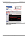
Checking of axis 1 positioning control:
Check if the axis 1 current feed value moves to 100.00 mm and returns to 0.0 mm.
Check if the axis 1 feedrate is the command speed.
Screen
Check Item
Value
Axis 1 Current feed value
—
Axis 1 Machine feed value
—
Axis operation status
Position Control
Axis feed rate
—
External input signal : Lower limit
ON
External input signal : Upper limit
ON
PLC READY
ON
LD77 READY
ON
Synchronization flag
ON
All axes servo ON
ON
Servo status : READY ON
Axis 1
Servo status : Servo ON
Axis 1
BUSY
Axis 1
Error detection
ON
ON
ON
none
Axis warning detection
none
Tab. 2-16:
Monitoring of axis 1
Operation check completed.
MELSEC-L Series, LD77MH Simple Motion Module Quick start guide
2 - 39
Simple Motion Module start-up
2 - 40
Operation check
Synchronous control start-up
3
Synchronous control start-up
This chapter explains the synchronous control.
In particular, the operation check of the synchronous control parameter, positioning data for synchronous control and synchronous control are explained.
For existing parameters and servo parameters, refer to chapter 2.
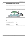
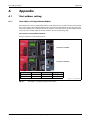
Cut on the fly
This is an example that makes the cutter axis (Axis 1) follow the operating conveyor axis (Axis 2) without stopping and cuts the center of a work piece. After cutting, the cutter axis moves to the standby
position. Synchronous control where an electronic cam is used in the cutter axis is executed.
Cutter axis
(cam control axis)
Axis 1
Work piece
Work piece
Work piece
Axis 2
Belt conveyor axis
Roller
device_2
Fig. 3-1:
Running cutoff device
Specifications
As the roller of the belt conveyer rotates once, a work piece on the belt conveyor moves for one work
step.
● Specifications of cutter axis (cam control axis)
Ball screw lead (PB)
Gear ratio of external reduction gear
Cam stroke
: 10 mm
: 1/2
: 100.0000 mm
● Specifications of belt conveyor
Roller diameter
Circumference of roller (= diameter × π )
Gear ratio of external reduction gear
MELSEC-L Series, LD77MH Simple Motion Module Quick start guide
: 50000 μm
: 157079.6 μm
: 1/1 (roller directly connected to a servomotor)
3-1
Synchronous control start-up
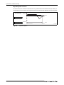
Operation pattern of device
The cutter axis (axis 1) moves constant distance in synchronization with the belt conveyor. After synchronization, the axis returns to the original position. The belt conveyor operates at constant speed.
Speed [mm/min]
2000.00
Time
Cutter axis
Speed [mm/min]
2000.00
Belt conveyor axis
Time
operation_2
Fig. 3-2:
3-2
Operation pattern
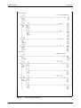
Start-up procedure in synchronous control
3.1
Synchronous control start-up
Start-up procedure in synchronous control
Following chart gives an overview of the operations and steps needed for starting up the synchronous control:
Start
2-axes system where synchronous control is available
Preparing devices
Refer to section 3.2
Refer to section 2.3
Installing modules
앫 Installing modules
앫 Installing batteries
앫 Installing DIN rails
Refer to section 2.4
Wiring and connecting cables
앫 Wiring the power supply module
앫 Wiring the power supply and the motor power to the
servo amplifier
앫 Setting the servo amplifier axis select rotary switch
앫 Connecting various cables
앫 Checking if the power is properly turned on
Refer to section 2.5
Installing application software
앫 Installing MELSOFT GX Works2
앫 Installing MR Configurator2
앫 Checking the start-up of MELSOFT GX Works2
Refer to section 2.6
Creating sequence programs for synchronous control
앫
앫
앫
앫
앫
앫
Creating a new project
Creating sequence programs
Saving a sequence program as a project
Connecting CPU module and personal computer
Formatting of the CPU module
Writing the sequence program to the PLC CPU
Refer to section 2.7
Creating parameter for synchronous control
앫
앫
앫
앫
앫
앫
앫
System setting
Parameter and servo parameter settings
Positioning data setting
Synchronous control parameter setting
Cam data setting
Saving a project
Writing to the Simple Motion Module
Refer to section 3.3
Operation check
앫
앫
앫
앫
OPR (for establishing a home position)
Start-up of drive axis
Operation check of a synchronous axis
Operation check with digital oscilloscope
Refer to section 3.4
End
MELSEC-L Series, LD77MH Simple Motion Module Quick start guide
3-3
Synchronous control start-up
3.2
2-axes system where synchronous control is available
2-axes system where synchronous control is available
The following shows the configuration example of a system which combines LD77MH4, MR-J3-B/MRJ4(W)-B and a servomotor.
Personal
computer
∼
USB cable
No-fuse breaker
(NFB)
LD77MH4
L61P
Circuit
Protector
(CP)
CP
SSCNET III cable
L26CPU-BT
To 1)
No-fuse breaker
(NFB)
From
1)
NFB
MR-J3-B/
MR-J4(W)-B
MR-J3-B
MR-J3-B/
MR-J4(W)-B
MR-J3-B
Magnetic
contactor
(MC)
Motor
power
supply cable
Servo motor
MC
Encoder cable
Motor power
supply cable
Encoder
cable
Servo motor
config_example_chap3E
Fig. 3-3:
3-4
System configuration for synchronous control with 2 axes
Creating parameter for synchronous control
Synchronous control start-up
3.3
Creating parameter for synchronous control
3.3.1
System setting
Set the system configuration for 2 axes:
screen_080
Fig. 3-4:
System configuration for 2 axes
MELSEC-L Series, LD77MH Simple Motion Module Quick start guide
3-5
Synchronous control start-up
3.3.2
Creating parameter for synchronous control
Parameter and servo parameter settings
Set parameters and servo parameters of axis 1 and 2. Please refer to section 2.8.5 "Parameter setting"
and section 2.8.6 "Servo parameter setting" for details of the setting procedure.
The setting list is given in section A.2 "Parameter and positioning data".
The electronic gear settings of the belt conveyor are described as follows:
Input:
Machine Components
Unit Setting
Diameter of Roll (DR) [μm]
Reduction Gear Ratio (Load side (NL)/ Motor side (NM))
Encoder Resolution [pls/rev]
:
:
:
:
:
Conveyor
0: mm
50000.0
1/1
262144
Calculation result for basic parameters 1:
Unit Setting
No. of Pulses per Revolution
Movement Amount per Rotation
Unit Magnification
: 0: mm
: 4625519 PLS
: 2771663.0 μm
: 1: × 1 Times
Input
Calculation result
screen_082J
Fig. 3-5:
3-6
Parameter settings of axis 1
Creating parameter for synchronous control
3.3.3
Synchronous control start-up
Positioning data setting
Create a program where the belt conveyor (axis 2) moves to P1 from the home position.
Create a cam data in synchronization with the belt conveyor for the axis 1 which executes the cam
control.
Example
Example of positioning data moving to P1 from home position.
Position of belt conveyor (axis 2) [mm]
If the roller with a diameter of 50 mm
rotates one time, the belt conveyor
moves for 157.0796 mm.
P1 = 157.0796
P0 = 0.0
Time
Speed [mm/min]
2000.00
Time
Position of cutter axis (axis 1) [mm]
Execute the cam control for following
the movement of the belt conveyor.
P1 = 100.0
P0 = 0.0
Time
operation_3E
Fig. 3-6:
Operation pattern of the example
Selecting the positioning data
Select Intelligent Function Module LD77MH4 Positioning Data Axis #2 Positioning
Data to display the "Positioning Data" screen.
screen_036E
Fig. 3-7:
Selecting the positioning data
Axis 2 Positioning data
No.
Operation
pattern
Control
system
1
0:
Completion
INC
linear 1
Tab. 3-1:
Axis to be Accelerainterpolat- tion time
ed
No.
—
1: 1000
Deceleration time
No.
1: 1000
Positioning address
157079.6
μm
Arc
address
0.0
μm
Command Dwell
speed
time M code
2000.00
mm/min
0 ms
0
Axis 2 Positioning data
MELSEC-L Series, LD77MH Simple Motion Module Quick start guide
3-7
Synchronous control start-up
3.3.4
Creating parameter for synchronous control
Synchronous control parameter setting
Set a parameter of the axis 1 that executes cam operation in synchronization with the current feed value of the axis 2 servo input axis.
Item
Description
Input axis parameter
Set the servo input axis type for the main axis.
("1: Current feed value" for the axis 2)
Synchronous parameter axis 1
Set the synchronous control parameter of the axis 1.
Tab. 3-2:
Parameter setting
Synchronous control parameter screen start-up
Select Intelligent Function Module LD77MH4 Synchronous Control Parameter Axis #1
Synchronous Parameter.
Click the setting area of "Main Input Axis" to display the contents that can be set.
Select the "Type": 1: Servo input axis.
screen_037E
Fig. 3-8:
3-8
Setting of synchronous parameters
Creating parameter for synchronous control
Synchronous control start-up
In the same way, change the underlined part of synchronous parameter axis 1 as shown in
following table:
Item
Description
Main input axis No.
Main shaft
Sub input axis No.
Main shaft composition gear
Main shaft gear
Type
2
Type
0: Invalid
Axis No.
0
Main
1: Input+
Sub
0: Not input
Numerator
1
Denominator
Main shaft clutch control
setting
1
ON control mode
0: No Clutch (Direct Coupled Operation)
OFF control mode
0: OFF Control Invalid
High speed input request
signal
0
Main shaft clutch reference address setting
Main shaft clutch ON address
Main shaft clutch Travel value before main shaft clutch ON
Auxiliary shaft
1: Servo input axis
Axis No.
0: Current Value after Main Shaft Composite
Gear
0 pls/rev
0 pls/rev
Main shaft clutch OFF address
0 pls/rev
Travel value before main shaft clutch OFF
0 pls/rev
Main shaft clutch smoothing system
0: Direct
Main shaft clutch smoothing time constant
0 ms
Slippage at main shaft clutch ON
0 pls/rev
Slippage at main shaft clutch OFF
0 pls/rev
Type
0: Invalid
Axis No.
0
Auxiliary shaft
composite gear
Main shaft
1: Input+
Auxiliary shaft
0: No Input
Auxiliary shaft
gear
Numerator
1
Denominator
Auxiliary shaft clutch control setting
Auxiliary shaft
clutch
Speed change
gear
0: No Clutch (Direct Coupled Operation)
OFF control mode
0: OFF Control Invalid
High speed input request
signal
0
Auxiliary shaft clutch reference address setting
0: Current Value after Main Shaft Composite
Gear
Auxiliary shaft clutch ON address
0 pls/rev
Travel value before auxiliary shaft clutch ON
0 pls/rev
Auxiliary shaft clutch OFF address
0 pls/rev
Travel value before auxiliary shaft clutch OFF
0 pls/rev
Auxiliary shaft clutch smoothing system
0: Direct
Auxiliary shaft clutch smoothing time constant
0 ms
Slippage at auxiliary shaft clutch ON
0 pls/rev
Slippage at auxiliary shaft clutch OFF
0 pls/rev
Speed change gear arrangement
0: No transmission
Speed change gear smoothing time constant
0 ms
Speed change ratio
Tab. 3-3:
1
ON control mode
Numerator
1
Denominator
1
Synchronous parameter settings for axis 1 (1)
MELSEC-L Series, LD77MH Simple Motion Module Quick start guide
3-9
Synchronous control start-up
Creating parameter for synchronous control
Item
Description
Cam axis cycle unit
Unit setting selection
0: Use units of Main Input axis
Unit
0 mm
number of decimal places
Output axis
157.0796 mm
Cam stroke amount
100000.0 μm
Cam No.
1
Cam axis phase correction advance time
0 μs
Cam axis phase correction time constant
10 ms
Output axis smoothing time constant
0 ms
Current value per cycle
after main shaft gear
Current value per cycle
Synchronous
after auxiliary shaft gear
control initial
position parameter
Cam reference position
Cam axis current value per
cycle
Tab. 3-3:
0
Cam axis length per cycle
Setting method
0: Previous Value
Initial setting value
0 pls/rev
Setting method
0: Previous Value
Initial setting value
0 pls/rev
Cam axis position recovery
target
0: Cam Axis Current Value per Cycle Recovery
Setting method
2: Current Feed Value
Initial setting value
0.0 μm
Setting method
0: Previous Value
Initial setting value
0 pls/rev
Synchronous parameter settings for axis 1 (2)
Input axis parameter setting of synchronous control parameter
Select Intelligent Function Module LD77MH4 Synchronous Control Parameter Input
Axis Parameter.
Setting example of operating axis 1 in synchronization with the current feed value
of the axis 2
screen_038E
Fig. 3-9:
Input axis parameter setting of synchronous control parameter
Input axis parameter (Axis 2)
Item
Description
Servo input axis type
Input smoothing time constant
Servo input axis
Tab. 3-4:
Detail setting
1: Current feed value
0 ms
Phase correction advance time
0 µs
Phase correction time constant
10 ms
Rotation direction restriction
0: Without Rotation Direction
Restriction
Parameter settings for axis 2
Setting of synchronous control parameter and input axis parameter completed.
3 - 10
Creating parameter for synchronous control
3.3.5
Synchronous control start-up
Cam data setting
Cam data screen start-up
Right-click Cam data and select Add new data. The "New Data" screen is displayed.
Set the Cam No.
Click the OK button. The initial screen to create cam data is displayed.
screen_039E
Fig. 3-10:
Setting of cam data
MELSEC-L Series, LD77MH Simple Motion Module Quick start guide
3 - 11
Synchronous control start-up
Creating parameter for synchronous control
Creating cam data
When the stroke and cam curve is set as (b), the cam graph appears as (a).
(a)
(b)
Setting details as in following table
Section No.
Start point [degree]
End point [degree]
Stroke [%]
Cam curve
1
0.00000
2.00000
0.0500000
Constant speed
2
2.00000
4.00000
0.5000000
Constant speed
3
4.00000
6.00000
1.1000000
Constant speed
4
6.00000
8.00000
1.9000000
Constant speed
5
8.00000
113.59160
50.0000000
Constant speed
6
113.59160
222.00000
98.1000000
Constant speed
7
222.00000
224.00000
98.9000000
Constant speed
8
224.00000
226.00000
99.5000000
Constant speed
9
226.00000
228.00000
99.9000000
Constant speed
10
228.00000
229.18320
1000.000000
Constant speed
11
229.18320
0.00000
0.0000000
Dist. const. speed
screen_040E
Fig. 3-11:
Cam data
Saving a project
Refer to the previous section 2.8.8 "Saving the Simple Motion Module as a project".
Writing to the Simple Motion Module
Refer to the previous section 2.8.9 "Writing to the Simple Motion Module".
Synchronous control parameter setting is completed.
3 - 12
Operation check of synchronous control
3.4
Synchronous control start-up
Operation check of synchronous control
For details of the operation check for JOG operation, OPR and positioning control, refer to chapter 2.
This section explains the operation check of the synchronous control.
Following the procedure below, the axis 1 executes the cam control in synchronization with the current feed value of the axis 2.
Item
Device
OPR command
X53
Set the OPR No.
Axis 1 positioning start
X71
Turn ON the axis 1 positioning start Y40 and start OPR of the axis 1.
Axis 2 positioning start
X72
Turn ON the axis 2 positioning start Y41 and start OPR of the axis 2.
—
—
Turn OFF X71 and X72 once.
Synchronous control axis setting
X7D
Set the synchronous control axis and G36320 to 1.
Synchronous positioning No.
setting
X56
Set positioning No. for the synchronous control.
Axis 2 positioning start
X72
Turn ON the positioning start of the axis 2 and start the synchronous
control.
Tab. 3-5:
3.4.1
Description
Devices for checking synchronous control
OPR (for establishing a home position)
Execute the OPR of the axis 2.
For details of the operation check for the OPR of the axis 1, refer to chapter 2.
Turn "Machine OPR command" (X53) ON.
Turn "Positioning start command" (axis 2) (X72) ON.
Double-click with pressing the
[SHIFT] key.
Double-click with pressing the
[SHIFT] key.
screen_041E
Fig. 3-12:
OPR operation check of axis 2
OPR completed.
MELSEC-L Series, LD77MH Simple Motion Module Quick start guide
3 - 13
Synchronous control start-up
3.4.2
Operation check of synchronous control
Start-up of drive axis
Turn ON Synchronous control axis setting (X7D), and set H1 to the buffer memory (U3\G36320)
and the axis 1 as the synchronous control axis.
Double-click with pressing the
[SHIFT] key.
screen_042E
Fig. 3-13:
Setting axis 1 as synchronous control axis
Checking the axis 1 BUSY signal
Check if the axis 1 BUSY signal is turned ON when setting H1 to the buffer memory (U3\G36320)
of the synchronous control start.
Screen
Axis 1
Synchronous Control
BUSY
Tab. 3-6:
3 - 14
Checking operation status of axis 1
Axis 2
Operation check of synchronous control
Synchronous control start-up
Setting the axis 2 program No.
Double-click with pressing the
[SHIFT] key.
screen_043E
Fig. 3-14:
Set positioning No. for the synchronous control
Starting the axis 2 program
Turn Positioning start command (X72) ON.
Double-click with pressing the
[SHIFT] key.
screen_044E
Fig. 3-15:
3.4.3
Starting of synchronous control
Operation check of a synchronous axis
Check if the servomotors of the axis 1 and 2 operate.
Screen
Tab. 3-7:
Axis 1
Axis 2
—
—
—
—
Synchronous Control
—
Positioning Control
2000.00 mm/min
ON
ON
ON
ON
Monitoring axes 1 and 2
Operation check with the intelligent function module is completed.
MELSEC-L Series, LD77MH Simple Motion Module Quick start guide
3 - 15
Synchronous control start-up
3.4.4
Operation check of synchronous control
Operation check with digital oscilloscope (check of cam operation)
This section explains the method for checking the cam operation with the assistant function of the
digital oscilloscope.
Starting the digital oscilloscope:
Select Intelligent Function Module LD77MH4 Digital Oscilloscope.
screen_045E
Fig. 3-16:
3 - 16
"Digital Oscilloscope" screen
Operation check of synchronous control
Synchronous control start-up
Click the Assistant Screen button to start the "Assistant" screen.
The section "Communicate with the simple motion module and sample the data" provides
operation items for setting of the digital oscilloscope (see the following steps to ).
Select "1) Connect the personal computer with the simple motion module, and switch to [Online]".
The "Online Setting" screen is displayed, where you can set the following items::
앫 Sampling method: Module Buffering Method
앫 Operation mode: Online
Click OK to return to the "Assistant" screen.
Select "2) Select the probe item to be sampled". The "Assistant (Probe Selection)" screen is
displayed. Select the "Cam operation" from the list and Axis No. "1".
Click OK to return to the "Assistant" screen.
Select "3) Set the sampling condition". The "Assistant (Sampling Condition)" screen is displayed.
Set the items:
앫 Sampling rate (ms) : 0.888 × 1
앫 Sampling size (point): 8192
앫 Trigger balance (%) : 90.00
앫 After trigger
Sampling size (point): 7373
Sampling time (ms) : 6553.8
Click OK to return to the "Assistant" screen.
screen_046E
Fig. 3-17:
Functions of the assistant screen
MELSEC-L Series, LD77MH Simple Motion Module Quick start guide
3 - 17
Synchronous control start-up
Operation check of synchronous control
Setting the trigger condition:
After closing the "Assistant" screen, select Edit Trigger... to display the "TRIGGER" screen.
Select the Trigger Setting register card to display the screen for setting the trigger conditions .
Press the Pattern button repeatedly to display
.
Set the following items:
앫 Axis 1 - Cam Axis 1 Cycle Current Value (42812)
앫 Axis 1 - Cam Axis Current Feed Value (42816)
100 (x0.0001 mm)
10 (×0.1 μm)
screen_047E
Fig. 3-18:
Setting the trigger condition
Starting sampling
Display the "Assistant" screen again (see step ) and select "4) Start the sampling".
The following screen appears.
Click Yes to start sampling.
Fig. 3-19:
Confirmation screen to start the sampling
3 - 18
screen_048E
Operation check of synchronous control
Synchronous control start-up
Check the cam pattern with the digital oscilloscope.
Check if the pattern which created the cam data and the axis 1 current feed value of the digital
oscilloscope are the same.
Select View Cursor to display the explanation and value of each probe.
screen_049E
Fig. 3-20:
Cam pattern on the digital oscilloscope
Operation check completed.
MELSEC-L Series, LD77MH Simple Motion Module Quick start guide
3 - 19
Synchronous control start-up
3 - 20
Operation check of synchronous control
Start address setting
Appendix
A
Appendix
A.1
Start address setting
A.1.1
Start address of Simple Motion Module
CPU modules of L series are equipped with built-in I/O and built-in CC-Link (CC-Link only with L26CPUBT). If connecting a Simple Motion Module to the right side of a CPU module, the start XY address becomes the number that is added to the No. of I/O points corresponding to the CPU module equipment. Since the number depends on CPU modules, refer to the following table.
Start address of Simple Motion Module
The start addresses are the default values.
L26CPU-BT + LD77MH4
L26CPU-BT +LD77MH16
CPU module
LD77MH4
LD77MH16
L02CPU
00
10H
10H
L26CPU-BT
00
30H
30H
system_view_1, ld77mh4, ld77mh16
Fig. A-1:
Start address setting depending on CPU module
MELSEC-L Series, LD77MH Simple Motion Module Quick start guide
A-1
Appendix
A.1.2
Start address setting
Start address setting
When newly adding a Simple Motion Module, specify the start XY addresses to both of GX Works2 and
the Simple Motion Module Setting Tool.
GX Works2
Set the same address
Simple Motion Module Setting Tool
app1_001
Fig. A-2:
A-2
Start address setting
Parameter and positioning data
A.2
Appendix
Parameter and positioning data
This section shows the parameter and the positioning data that are used in this document.
A.2.1
Parameters
Item
Basic parameter 1
Basic parameter 2
Axis 1
Axis 2
Unit Setting
0: mm
0: mm
No. of pulses per revolution
16384 pls/rev
4625519 pls/rev
(262144 pls/rev)
Movement amount per revolution
312.5 μm
2771663.0 μm
(157079.6 μm)
Unit magnification
1: time
1: time
Bias speed at start
0.00 mm/min
0.00 mm/min
Speed limit value
30000.00 mm/min
30000.00 mm/min
Acceleration time
1000 ms
1000 ms
Deceleration time
1000 ms
1000 ms
Backlash compensation amount
0.0 μm
0.0 μm
Software stroke limit upper limit value
214748364.7 μm
214748364.7 μm
Software stroke limit lower limit value
-214748364.8 μm
-214748364.8 μm
Software stroke limit selection
0: Apply software stroke
limit on current feed value
0: Apply software stroke
limit on current feed value
Software stroke limit valid/invalid setting 0: Valid
0: Valid
Command in-position width
10.0 μm
10.0 μm
Torque limit setting value
300 %
300 %
M code ON signal output timing
0: WITH mode
0: WITH mode
Speed switching mode
0: Standard speed switching mode
0: Standard speed switching mode
Interpolation speed designation method 0: Composite speed
Detailed
parameter 1
Detailed
parameter 2
Tab. A-1:
0: Composite speed
Current feed value during speed control
0: Do not update current
feed value
0: Do not update current
feed value
Input signal logic selection lower limit
1: Positive logic
1: Positive logic
Input signal logic selection upper limit
1: Positive logic
1: Positive logic
Input signal logic selection: External
command/switching signal
0: Negative logic
Input signal logic selection: Near-point
dog signal
0: Negative logic
Input signal logic selection: Manual
pulse generator input
0: Negative logic
Input signal logic selection
1: Input of servo amplifier
1: Input of servo amplifier
Manual pulse generator input selection
0: A-phase/B-phase mode
(multiplied by 4)
0: A-phase/B-phase mode
(multiplied by 4)
Speed-position function selection
0: Speed-position switching control (INC mode)
0: Speed-position switching control (INC mode)
0: Negative logic
Forced stop valid/invalid selection
1: Invalid
Acceleration time 1
1000 ms
1000 ms
Acceleration time 2
1000 ms
1000 ms
Acceleration time 3
1000 ms
1000 ms
Deceleration time 1
1000 ms
1000 ms
Deceleration time 2
1000 ms
1000 ms
Deceleration time 3
1000 ms
1000 ms
Parameter data (1)
MELSEC-L Series, LD77MH Simple Motion Module Quick start guide
A-3
Appendix
Parameter and positioning data
Item
Detailed
parameter 2
Axis 1
Axis 2
JOG speed limit value
15000.00 mm/min
15000.00 mm/min
JOG operation acceleration time
selection
0: 1000
0: 1000
JOG operation deceleration time
selection
0: 1000
0: 1000
Acceleration / deceleration process
selection
0: Automatic trapezoidal
acceleration / deceleration
processing
0: Automatic trapezoidal
acceleration / deceleration
processing
S-pattern ratio
100 %
100 %
Sudden stop deceleration
1000 ms
1000 ms
Stop group 1 sudden stop selection
0: Normal deceleration stop 0: Normal deceleration stop
Stop group 2 sudden stop selection
0: Normal deceleration stop 0: Normal deceleration stop
Stop group 3 sudden stop selection
0: Normal deceleration stop 0: Normal deceleration stop
Positioning complete signal output time 300
300
Allowable circular interpolation error
width
10.0 μm
10.0 μm
External command function selection
0: External positioning start
0: External positioning start
Speed control 10 x multiplier setting for
degree axis
0: Invalid
0: Invalid
Restart allowable range when servo OFF
to ON
0 pls/rev
0 pls/rev
Manual pulse / INC synchronous encoder 0: Differential output type
input type selection
OPR basic
parameters
OPR detailed
parameters
Expansion
parameters
Operation setting for speed / torque
control mode: Speed default value
selection
0: Command speed
0: Command speed
Operation setting for speed-torque
control mode: Condition selection at
mode switching
0: Switching Conditions
Valid at Switching Mode
0: Switching Conditions
Valid at Switching Mode
External command signal selection 0: Unused
0: Unused
OPR method
6: Data set method
6: Data set method
OPR direction
0: Positive direction
(address increment
direction)
0: Positive direction
(address increment
direction)
OP address
0.0 μm
0.0 μm
OPR speed
0.01 mm/min
0.01 mm/min
Creep speed
0.01 mm/min
0.01 mm/min
OPR retry
0: Do not retry OPR with
limit switch
0: Do not retry OPR with
limit switch
Setting for the movement amount after
near-point dog ON
0.0 μm
0.0 μm
OPR acceleration time selection
0: 1000
0: 1000
OPR deceleration time selection
0:1000
0:1000
OP shift amount
0.0 μm
0.0 μm
OPR torque limit value
300 %
300 %
Operation setting for incompletion of
OPR
0: Positioning control is not
executed.
0: Positioning control is not
executed.
Speed designation during OP shift
0: OPR speed
0: OPR speed
Dwell time during OPR retry
0 ms
0 ms
Optional data monitor:
Data type setting 1
0: No Setting
0: No Setting
Optional data monitor:
Data type setting 2
0: No Setting
0: No Setting
Optional data monitor:
Data type setting 3
0: No Setting
0: No Setting
0: No Setting
0: No Setting
Optional data monitor:
Data type setting 4
Operation cycle setting
Tab. A-1:
A-4
1: 1.77 ms
Parameter data (2)
The Operation cycle setting and External command signal selection are used only in a parameter of
LD77MH16.
Parameter and positioning data
A.2.2
Appendix
Positioning data
Axis 1 Positioning data
No.
Operation
pattern
Control
system
Axis to be
interpolated
Acceleration time
No.
Deceleration time
No.
Positioning address
Arc
address
Command
speed
Dwell
time
M
code
1
1:
Continuation
ABS
linear 1
—
1: 1000
1: 1000
100000.0
μm
0.0
μm
2000.00
mm/min
0 ms
0
2
0:
Completion
ABS
linear 1
—
1: 1000
1: 1000
0.0
μm
0.0
μm
30000.00
mm/min
0 ms
0
Tab. A-2:
Axis 1 Positioning data
Axis 2 Positioning data
1
Operation pattern
Control
system
Axis to be
interpolated
Acceleration time
No.
Deceleration time
No.
Positioning address
Arc
address
Command
speed
Dwell
time
M
code
0:
Completion
INC
linear 1
—
1: 1000
1: 1000
157079.6
μm
0.0
μm
2000.00
mm/min
0 ms
0
Tab. A-3:
Axis 2 Positioning data
MELSEC-L Series, LD77MH Simple Motion Module Quick start guide
A-5
Appendix
Various monitor functions
A.3
Various monitor functions
A.3.1
Axis monitor
Select Axis Monitor
Select Intelligent Function Module Monitor Module Monitor Axis Monitor to display
the initial "Axis Monitor" screen.
Click Select Monitor Axis to display the "Select Monitor Axis" screen.
Select the displayed axis and click Add:
LD77MH4: Axis 1 to 4
LD77MH16: Axis 1 to 16
Click OK to return to the initial "Axis Monitor" screen.
app3_001
Fig. A-3:
A-6
Steps to of selecting axis monitor procedure
Various monitor functions
Appendix
Click Select Monitor Item to display the "Select Monitor Item" screen.
Select the monitoring item in the selectable item list.
Click Add to add the selected item to the monitor item list.
After selection of all desired monitor items click the OK button to return to the initial "Axis Monitor"
screen.
The statuses and values of the selected items are now shown for the selected axes.
app3_002
Fig. A-4:
Steps to of selecting axis monitor procedure
Selectable Items: Input signal, Output signal, Axis monitor data, Axis control data
Item
Selectable Item
Input signal (X)
Output signal (Y)
Tab. A-4:
Buffer memory address
LD77MH4
LD77MH16
M code ON
X4+n
—
Error detection
X8+n
—
BUSY
XC+n
X10+n
Start complete
X10+n
—
Positioning complete
X14+n
—
Axis stop
Y4+n
—
Forward JOG start
Y8+2n
—
Reverse JOG start
Y9+2n
—
Positioning start
Y10+n
Y10+n
Execution prohibition flag
Y14+n
—
List of selectable monitor items (1)
MELSEC-L Series, LD77MH Simple Motion Module Quick start guide
A-7
Appendix
Various monitor functions
Item
Selectable Item
Axis monitor data
LD77MH16
Current feed value
800+100n
2400+100n
Machine feed value
802+100n
2402+100n
Feedrate
804+100n
2404+100n
Axis error No.
806+100n
2406+100n
Axis warning No.
807+100n
2407+100n
Valid M code
808+100n
2408+100n
Axis operation status
809+100n
2409+100n
Current speed
810+100n
2410+100n
Axis federate
812+100n
2412+100n
Positioning amount of speed-position switching control
814+100n
2414+100n
External input signal
816+100n
2416+100n
Status
In speed control, Speed-position switching latch,
Command in-position, OPR request , OPR complete ,
Position-speed switching latch , Axis warning detection ,
Speed change 0 , M code On , error detection ,
start complete , positioning complete 817+100n
2417+100n
Target value
818+100n
2418+100n
Target speed
820+100n
2420+100n
Movement amount after near-point dog ON
824+100n
2424+100n
Torque limit stored value / Forward torque limit stored
value
826+100n
2426+100n
Special start data instruction: Code setting value
827+100n
2427+100n
Special start data instruction: Parameter setting value
828+100n
2428+100n
Start positioning data No. setting value
829+100n
2429+100n
In speed limit flag
830+100n
2430+100n
In speed change processing flag
831+100n
2431+100n
Special start repetition counter
832+100n
2432+100n
Control system repetition counter
833+100n
2433+100n
Start data pointer being executed
834+100n
2434+100n
Positioning data No. being executed
835+100n
2435+100n
Block No. being executed
836+100n
2436+100n
Last executed positioning data No.
837+100n
2437+100n
Positioning data being executed : M code
839+100n
2439+100n
Positioning data being executed : Dwell time
840+100n
2440+100n
—
2441+100n
Positioning data being executed : Command speed
842+100n
2442+100n
Positioning data being executed : Positioning address
844+100n
2444+100n
Positioning data being executed : Axis to be interpolated
Tab. A-4:
A-8
Buffer memory address
LD77MH4
Positioning data being executed : Arc address
846+100n
2446+100n
OPR re-movement amount
848+100n
2448+100n
Real current value
850+100n
2450+100n
Deviation counter value
852+100n
2452+100n
Motor rotation speed
854+100n
2454+100n
Motor current value
856+100n
2456+100n
Parameter error No
870+100n
2470+100n
Servo status 1:
Zero passage, Zero speed, Speed limit, PID control
876+100n
2476+100n
Servo status 2:
Control mode, Servo alarm, In-position, Torque limit,
Absolute position lost, Servo warning
877+100n
2477+100n
Regenerative load ratio / Optional data monitor output 1
878+100n
2478+100n
Effective load ratio / Optional data monitor output 2
879+100n
2479+100n
Peak load torque ratio / Optional data monitor output 3
880+100n
2480+100n
List of selectable monitor items (2)
Various monitor functions
Appendix
Item
Selectable Item
LD77MH4
LD77MH16
—
2481+100n
Semi / Fully closed loop status
887+100n
2487+100n
Servo alarm
888+100n
2488+100n
Optional data monitor output 4
Axis monitor data
Axis control data
Tab. A-4:
Buffer memory address
Reverse torque limit stored value
891+100n
2491+100n
Speed during command
892+100n
2492+100n
Torque during command
894+100n
2494+100n
Servo status 3 Continuous operation to torque control
858+100n
2458+100n
Control mode switching status
895+100n
2495+100n
Positioning start No.
1500+100n
4300+100n
Positioning starting point No.
1501+100n
4301+100n
Axis error reset
1502+100n
4302+100n
Restart command
1503+100n
4303+100n
M code OFF request
1504+100n
4304+100n
External command valid
1505+100n
4305+100n
New current value
1506+100n
4306+100n
New acceleration time value
1508+100n
4308+100n
New deceleration time value
1510+100n
4310+100n
Acceleration/deceleration time change during speed
change, enable/disable selection
1512+100n
4312+100n
Positioning operation speed override
1513+100n
4313+100n
New speed value
1514+100n
4314+100n
Speed change request
1516+100n
4316+100n
Inching movement amount
1517+100n
4317+100n
JOG speed
1518+100n
4318+100n
Interrupt request during continuous operation
1520+100n
4320+100n
OPR request flag OFF request
1521+100n
4321+100n
Manual pulse generator 1 pulse input magnification
1522+100n
4322+100n
Manual pulse generator enable flag
1524+100n
4324+100n
New torque value/ forward new torque value
1525+100n
4325+100n
Speed-position switching control movement amount
change register
1526+100n
4326+100n
Speed-position switching enable flag
1528+100n
4328+100n
Position-speed switching control speed change register
1530+100n
4330+100n
Position-speed switching enable flag
1532+100n
4332+100n
Target position change value (New address)
1534+100n
4334+100n
Target position change value (New speed)
1536+100n
4336+100n
Target position change request flag
1538+100n
4338+100n
Simultaneous starting axis start data No. (axis 1 start data
No.)
1540+100n
4340+100n
Simultaneous starting axis start data No. (axis 2 start data
No.)
1541+100n
4341+100n
Simultaneous starting axis start data No. (axis 3 start data
No.)
1542+100n
4342+100n
Simultaneous starting axis start data No. (axis 4 start data
No.)
1543+100n
4343+100n
Step mode
1544+100n
4344+100n
Step valid flag
1545+100n
4345+100n
Step start information
1546+100n
4346+100n
Skip command
1547+100n
4347+100n
Teaching data selection
1548+100n
4348+100n
Teaching positioning data No.
1549+100n
4349+100n
ABS direction in degrees
1550+100n
4350+100n
List of selectable monitor items (3)
MELSEC-L Series, LD77MH Simple Motion Module Quick start guide
A-9
Appendix
Various monitor functions
Item
Selectable Item
Axis control data
Tab. A-4:
A - 10
Buffer memory address
LD77MH4
LD77MH16
Servo OFF command
1551+100n
4351+100n
Torque output setting value
1552+100n
4352+100n
Gain changing command
1559+100n
4359+100n
Torque change function switching request
1563+100n
4363+100n
New reverse torque value
1564+100n
4364+100n
Parameter write request
1554+100n
4354+100n
Parameter No.
1555+100n
4355+100n
Change data
1556+100n
4356+100n
Semi/Fully closed loop switching request
1558+100n
4358+100n
PI-PID switching request
1565+100n
4365+100n
Device selection for speed <--> position switching
1566+100n
4366+100n
Speed <-->position switching command
1567+100n
4367+100n
Control mode switching request
1574+100n
4374+100n
Control mode setting
1575+100n
4375+100n
Command speed at speed control mode
1576+100n
4376+100n
Acceleration time at speed control mode
1578+100n
4378+100n
Deceleration time at speed control mode
1579+100n
4379+100n
Command torque at torque control mode
1580+100n
4380+100n
Torque time constant at torque control mode
(Forward direction)
1581+100n
4381+100n
Torque time constant at torque control mode
(Reverse direction)
1582+100n
4382+100n
Speed limit value at torque control mode
1584+100n
4384+100n
Speed limit value at continuous operation to torque
control
1586+100n
4386+100n
Acceleration time at continuous operation to torque
control
1588+100n
4388+100n
Deceleration time at continuous operation to torque
control
1589+100n
4389+100n
Target torque at continuous operation to torque control
1590+100n
4390+100n
Torque time constant at continuous operation to torque
control ( Forward direction)
1591+100n
4391+100n
Torque time constant at continuous operation to torque
control ( Reverse direction)
1592+100n
4392+100n
Control mode switching conditions
1593+100n
4393+100n
Control mode switching conditions (parameter)
1594+100n
4394+100n
Axis stop
—
30100+10n
Forward run JOG start
—
30101+10n
Reverse run JOG start
—
30102+10n
Execution prohibition flag
—
30103+10n
List of selectable monitor items (4)
M code On , Error detection, Start complete and Positioning complete are defined in input signal (X) of
LD77MH.
Various monitor functions
Appendix
Selectable Items: Synchronous control monitor / Synchronous control data
Buffer memory address
Item
Synchronous
control monitor
Synchronous
control data
Tab. A-5:
Selectable Item
LD77MH4
LD77MH16
Current value after main shaft composite gear
42800+40n
Current value per cycle after main shaft gear
42802+40n
Current value per cycle after auxiliary shaft gear
42804+40n
Cam axis phase correction amount
42810+40n
Cam axis current value per cycle
42812+40n
Cam reference position
42814+40n
Cam axis current feed value
42816+40n
Execute cam No.
42818+40n
Execute cam stroke amount
42820+40n
Main shaft clutch ON/OFF status
42828+40n
Main shaft clutch smoothing status
42829+40n
Main shaft clutch slippage (cumulative)
42830+40n
Auxiliary shaft clutch ON/OFF status
42832+40n
Auxiliary shaft clutch smoothing status
42833+40n
Auxiliary shaft clutch slippage(cumulative)
42834+40n
Main shaft clutch command
44080+20n
Main shaft clutch control invalid command
44081+20n
Main shaft clutch force OFF command
44082+20n
Auxiliary shaft clutch command
44083+20n
Auxiliary shaft clutch control invalid command
44084+20n
Auxiliary shaft clutch force OFF command
44085+20n
Synchronous control change request
44086+20n
Synchronous control change command
44087+20n
Synchronous control change value
44088+20n
Synchronous control change reflection time
44090+20n
List of selectable monitor items for synchronous control
MELSEC-L Series, LD77MH Simple Motion Module Quick start guide
A - 11
Appendix
A.3.2
Various monitor functions
Error history of Simple Motion Module Setting Tool
Error codes and warning codes at debugging a Simple Motion Module can be referred.
Select Intelligent Function Module Monitor Module Monitor Error History to display
the "Error History" screen.
Click the Create CSV File button to save the error history as a CSV file.
The "Save to CSV file" screen is displayed.
Specify a file name.
Click the Save button to preserve the error history.
app3_003
Fig. A-5:
A - 12
Procedure of saving the error history as a CSV file
Various monitor functions
A.3.3
Appendix
PLC diagnostics of GX Works2
Error codes and warning codes at debugging a sequence program can be referred.
Select Diagnostics PLC Diagnostics....
The "PLC Diagnostics" screen with error information is displayed.
app3_004
Fig. A-6:
PLC diagnostics
MELSEC-L Series, LD77MH Simple Motion Module Quick start guide
A - 13
Appendix
A.4
b
Sample program
Sample program
CAUTION:
● This sequence program is an example using LD77MH4 and L26CPU-BT. When other modules
are used, the assignment of the signals is different. Please refer to the user's manual (chapter
of the positioning control) for details of each signal.
● The sequence program of this appendix is used in this start-up guidance. Be sure to add and
verify the conformance with the desired system before diverting the programs of this appendix to the actual system.
This sequence program is an excerpt from the User’s Manual (Positioning Control) for the MELSEC-L
LD77MH Simple Motion Module. For details refer to the chapter "Positioning program examples" in
the User's Manual.
A.4.1
Used device list
Classification
Input
Output
Tab. A-6:
A - 14
Device No.
Signal name
Signal
X30
PLC ready completion signal
X31
Synchronization flag
X38
Axis 1 error detection signal
LD77MH
X39
Axis 2 error detection signal
X3C
Axis 1 BUSY signal
X3D
Axis 2 BUSY signal
PLC CPU
X40
Axis 1 start complete signal
X41
Axis 2 start complete signal
X50
JOG operation speed setting command
X53
Machine OPR No. setting
X55
Positioning No. setting
X56
Synchronous positioning No. setting
X5D
JOG operation speed setting command
X5E
Forward rotation JOG command
X5F
Reverse rotation JOG command
X6E
Error reset command
X6F
Stop command
X71
Axis 1 positioning start command
X72
Axis 2 positioning start command
X7B
PLC ready ON
X7D
Synchronous control axis setting
Y30
PLC ready signal
Y31
All-axes servo ON signal
Y34
Axis 1 stop signal
Y38
Axis 1 forward rotation JOG start signal
Y39
Axis 1 reverse rotation JOG start signal
Y40
Axis 1 positioning start signal
Y41
Axis 2 positioning start signal
List of used devices
Input unit
PLC CPU
PLC CPU
LD77MH
Sample program
A.4.2
Appendix
Sequence program example for synchronous control with 2 axes
app4_001
Fig. A-7:
Sequence program example (1 )
MELSEC-L Series, LD77MH Simple Motion Module Quick start guide
A - 15
Appendix
Sample program
app4_002
Fig. A-8:
A - 16
Sequence program example (2 )
Sample program
Appendix
app4_003
Fig. A-9:
Sequence program example (3)
MELSEC-L Series, LD77MH Simple Motion Module Quick start guide
A - 17
Appendix
Sample program
app4_004
Fig. A-10:
A - 18
Sequence program example (4)
Sample program
Appendix
app4_005
Fig. A-11:
Sequence program example (5)
MELSEC-L Series, LD77MH Simple Motion Module Quick start guide
A - 19
Appendix
A - 20
Sample program
Index
Index
A
Axis select rotary switch . . . . . . . . . . . . . . . . . . . . . . . . . . .2-7
C
Connections
P
Parameter
Axis parameter . . . . . . . . . . . . . . . . . . . . . . . . . . . . . . .A-3
Positioning data
Settings overview . . . . . . . . . . . . . . . . . . . . . . . . . . . .A-3
CPU module and PC . . . . . . . . . . . . . . . . . . . . . . . . 2-14
Settings . . . . . . . . . . . . . . . . . . . . . . . . . . . . . . . . . . . . 2-14
CPU module
Preparation
Devices . . . . . . . . . . . . . . . . . . . . . . . . . . . . . . . . . . . . . . 2-4
Project
Formatting . . . . . . . . . . . . . . . . . . . . . . . . . . . . . . . . . 2-15
New . . . . . . . . . . . . . . . . . . . . . . . . . . . . . . . . . . . . . . . . .2-19
Write sequence programs . . . . . . . . . . . . . . . . . . . 2-16
Save . . . . . . . . . . . . . . . . . . . . . . . . . . . . . . . . . . . . . . . .2-13
Create
S
New project . . . . . . . . . . . . . . . . . . . . . . . . . . . . . . . . 2-11
New project (with Setting Tool) . . . . . . . . . . . . . 2-19
Sequence programs . . . . . . . . . . . . . . . . . . . . . . . . 2-12
I
Installation
Sample data
Creation of sequence programs . . . . . . . . . . . . . .2-12
Program example . . . . . . . . . . . . . . . . . . . . . . . . . . A-14
Setting procedures . . . . . . . . . . . . . . . . . . . . . . . . . .2-30
Setting
Application software . . . . . . . . . . . . . . . . . . . . . . . . . .2-9
Axis select rotary switch . . . . . . . . . . . . . . . . . . . . . . 2-7
Batteries . . . . . . . . . . . . . . . . . . . . . . . . . . . . . . . . . . . . . .2-5
Basic parameters . . . . . . . . . . . . . . . . . . . . . . . . . . . .2-21
DIN rails . . . . . . . . . . . . . . . . . . . . . . . . . . . . . . . . . . . . . .2-5
Positioning data . . . . . . . . . . . . . . . . . . . . . . . . . . . . .2-26
Modules . . . . . . . . . . . . . . . . . . . . . . . . . . . . . . . . . . . . . .2-5
Servo parameters . . . . . . . . . . . . . . . . . . . . . . . . . . . .2-25
M
MELSOFT GX Works2
Simple Motion Module
Add with Setting Tool . . . . . . . . . . . . . . . . . . . . . . .2-17
Error history . . . . . . . . . . . . . . . . . . . . . . . . . . . . . . . . A-12
Start . . . . . . . . . . . . . . . . . . . . . . . . . . . . . . . . . . . . . . . . 2-10
Monitor functions . . . . . . . . . . . . . . . . . . . . . . . . . . . . . . . . A-6
O
Operation check
Cam operation (synchronous control) . . . . . . . 3-16
JOG operation . . . . . . . . . . . . . . . . . . . . . . . . . . . . . . 2-31
OPR (Original Point Return) . . . . . . . . . . . . . . . . . 2-36
OPR (synchronous control) . . . . . . . . . . . . . . . . . . 3-13
Positioning control . . . . . . . . . . . . . . . . . . . . . . . . . 2-38
Start-up of drive axis (synchronous control) . . 3-14
Synchronous axis (synchronous control) . . . . . 3-15
Setting Tool . . . . . . . . . . . . . . . . . . . . . . . . . . . . . . . . .2-18
Start address . . . . . . . . . . . . . . . . . . . . . . . . . . . . . . . . .A-1
Write to . . . . . . . . . . . . . . . . . . . . . . . . . . . . . . . . . . . . .2-29
Software tools
MELSOFT GX Works2 . . . . . . . . . . . . . . . . . . . . . . . . . 2-9
MR Configurator2 . . . . . . . . . . . . . . . . . . . . . . . . . . . . 2-9
Synchronous control
Cam data setting . . . . . . . . . . . . . . . . . . . . . . . . . . . .3-11
Control parameter setting . . . . . . . . . . . . . . . . . . . . 3-8
Operation check . . . . . . . . . . . . . . . . . . . . . . . . . . . . .3-13
Parameter setting . . . . . . . . . . . . . . . . . . . . . . . . . . . . 3-6
Positioning data setting . . . . . . . . . . . . . . . . . . . . . . 3-7
Servo parameter setting . . . . . . . . . . . . . . . . . . . . . . 3-6
System configuration . . . . . . . . . . . . . . . . . . . . . . . . . 3-5
System configuration
Setting . . . . . . . . . . . . . . . . . . . . . . . . . . . . . . . . . . . . . .2-20
MELSEC-L Series – Simple Motion Modules LD77MH
i
Index
W
Wiring
Example . . . . . . . . . . . . . . . . . . . . . . . . . . . . . . . . . . . . . .2-6
Power supply module . . . . . . . . . . . . . . . . . . . . . . . . .2-6
Tightening torques . . . . . . . . . . . . . . . . . . . . . . . . . . .2-6
Wire sizes . . . . . . . . . . . . . . . . . . . . . . . . . . . . . . . . . . . . .2-6
ii
MITSUBISHI ELECTRIC
HEADQUARTERS
EUROPEAN REPRESENTATIVES
EUROPEAN REPRESENTATIVES
MITSUBISHI ELECTRIC EUROPE B.V.
EUROPE
German Branch
Gothaer Straße 8
D-40880 Ratingen
Phone: +49 (0)2102 / 486-0
Fax: +49 (0)2102 / 486-1120
MITSUBISHIELECTRICEUROPEB.V.-org.sl. CZECH REP.
Czech Branch
Avenir Business Park, Radlická 714/113a
CZ-158 00 Praha 5
Phone: +420 - 251 551 470
Fax: +420 - 251-551-471
MITSUBISHI ELECTRIC EUROPE B.V.
FRANCE
French Branch
25, Boulevard des Bouvets
F-92741 Nanterre Cedex
Phone: +33 (0)1 / 55 68 55 68
Fax: +33 (0)1 / 55 68 57 57
MITSUBISHI ELECTRIC EUROPE B.V.
IRELAND
Irish Branch
Westgate Business Park, Ballymount
IRL-Dublin 24
Phone: +353 (0)1 4198800
Fax: +353 (0)1 4198890
MITSUBISHI ELECTRIC EUROPE B.V.
ITALY
Italian Branch
Viale Colleoni 7
I-20041 Agrate Brianza (MB)
Phone: +39 039 / 60 53 1
Fax: +39 039 / 60 53 312
MITSUBISHI ELECTRIC EUROPE B.V.
POLAND
Poland Branch
Krakowska 50
PL-32-083 Balice
Phone: +48 (0)12 / 630 47 00
Fax: +48 (0)12 / 630 47 01
MITSUBISHI ELECTRIC EUROPE B.V.
RUSSIA
52, bld. 3 Kosmodamianskaya nab 8 floor
RU-115054 Мoscow
Phone: +7 495 721-2070
Fax: +7 495 721-2071
MITSUBISHI ELECTRIC EUROPE B.V.
SPAIN
Spanish Branch
Carretera de Rubí 76-80
E-08190 Sant Cugat del Vallés (Barcelona)
Phone: 902 131121 // +34 935653131
Fax: +34 935891579
MITSUBISHI ELECTRIC EUROPE B.V.
UK
UK Branch
Travellers Lane
UK-Hatfield, Herts. AL10 8XB
Phone: +44 (0)1707 / 27 61 00
Fax: +44 (0)1707 / 27 86 95
MITSUBISHI ELECTRIC CORPORATION
JAPAN
Office Tower “Z” 14 F
8-12,1 chome, Harumi Chuo-Ku
Tokyo 104-6212
Phone: +81 3 622 160 60
Fax: +81 3 622 160 75
MITSUBISHI ELECTRIC AUTOMATION, Inc.
USA
500 Corporate Woods Parkway
Vernon Hills, IL 60061
Phone: +1 847 478 21 00
Fax: +1 847 478 22 53
GEVA
AUSTRIA
Wiener Straße 89
AT-2500 Baden
Phone: +43 (0)2252 / 85 55 20
Fax: +43 (0)2252 / 488 60
TECHNIKON
BELARUS
Oktyabrskaya 19, Off. 705
BY-220030 Minsk
Phone: +375 (0)17 / 210 46 26
Fax: +375 (0)17 / 210 46 26
ESCO DRIVES & AUTOMATION
BELGIUM
Culliganlaan 3
BE-1831 Diegem
Phone: +32 (0)2 / 717 64 30
Fax: +32 (0)2 / 717 64 31
Koning & Hartman b.v.
BELGIUM
Woluwelaan 31
BE-1800 Vilvoorde
Phone: +32 (0)2 / 257 02 40
Fax: +32 (0)2 / 257 02 49
INEA RBT d.o.o.
BOSNIA AND HERZEGOVINA
Aleja Lipa 56
BA-71000 Sarajevo
Phone: +387 (0)33 / 921 164
Fax: +387 (0)33/ 524 539
AKHNATON
BULGARIA
4, Andrei Ljapchev Blvd., PO Box 21
BG-1756 Sofia
Phone: +359 (0)2 / 817 6000
Fax: +359 (0)2 / 97 44 06 1
INEA RBT d.o.o.
CROATIA
Losinjska 4 a
HR-10000 Zagreb
Phone: +385 (0)1 / 36 940 - 01/ -02/ -03
Fax: +385 (0)1 / 36 940 - 03
AutoCont C.S. s.r.o.
CZECH REPUBLIC
Technologická 374/6
CZ-708 00 Ostrava-Pustkovec
Phone: +420 595 691 150
Fax: +420 595 691 199
Beijer Electronics A/S
DENMARK
Lykkegårdsvej 17
DK-4000 Roskilde
Phone: +45 (0)46/ 75 76 66
Fax: +45 (0)46 / 75 56 26
Beijer Electronics Eesti OÜ
ESTONIA
Pärnu mnt.160i
EE-11317 Tallinn
Phone: +372 (0)6 / 51 81 40
Fax: +372 (0)6 / 51 81 49
Beijer Electronics OY
FINLAND
Peltoie 37
FIN-28400 Ulvila
Phone: +358 (0)207 / 463 540
Fax: +358 (0)207 / 463 541
UTECO
GREECE
5, Mavrogenous Str.
GR-18542 Piraeus
Phone: +30 211 / 1206 900
Fax: +30 211 / 1206 999
MELTRADE Kft.
HUNGARY
Fertő utca 14.
HU-1107 Budapest
Phone: +36 (0)1 / 431-9726
Fax: +36 (0)1 / 431-9727
Beijer Electronics SIA
LATVIA
Ritausmas iela 23
LV-1058 Riga
Phone: +371 (0)784 / 2280
Fax: +371 (0)784 / 2281
Beijer Electronics UAB
LITHUANIA
Savanoriu Pr. 187
LT-02300 Vilnius
Phone: +370 (0)5 / 232 3101
Fax: +370 (0)5 / 232 2980
ALFATRADE Ltd.
MALTA
99, Paola Hill
Malta- Paola PLA 1702
Phone: +356 (0)21 / 697 816
Fax: +356 (0)21 / 697 817
INTEHSIS srl
MOLDOVA
bld. Traian 23/1
MD-2060 Kishinev
Phone: +373 (0)22 / 66 4242
Fax: +373 (0)22 / 66 4280
HIFLEX AUTOM.TECHNIEK B.V.
NETHERLANDS
Wolweverstraat 22
NL-2984 CD Ridderkerk
Phone: +31 (0)180 – 46 60 04
Fax: +31 (0)180 – 44 23 55
Koning & Hartman b.v.
NETHERLANDS
Haarlerbergweg 21-23
NL-1101 CH Amsterdam
Phone: +31 (0)20 / 587 76 00
Fax: +31 (0)20 / 587 76 05
Beijer Electronics AS
NORWAY
Postboks 487
NO-3002 Drammen
Phone: +47 (0)32 / 24 30 00
Fax: +47 (0)32 / 84 85 77
Fonseca S.A.
PORTUGAL
R. João Francisco do Casal 87/89
PT - 3801-997 Aveiro, Esgueira
Phone: +351 (0)234 / 303 900
Fax: +351 (0)234 / 303 910
Sirius Trading & Services srl
ROMANIA
Aleea Lacul Morii Nr. 3
RO-060841 Bucuresti, Sector 6
Phone: +40 (0)21 / 430 40 06
Fax: +40 (0)21 / 430 40 02
INEA RBT d.o.o.
SERBIA
Izletnicka 10
SER-113000 Smederevo
Phone: +381 (0)26 / 615 401
Fax: +381 (0)26 / 615 401
SIMAP s.r.o.
SLOVAKIA
Jána Derku 1671
SK-911 01 Trencín
Phone: +421 (0)32 743 04 72
Fax: +421 (0)32 743 75 20
PROCONT, spol. s r.o. Prešov
SLOVAKIA
Kúpelná 1/A
SK-080 01 Prešov
Phone: +421 (0)51 7580 611
Fax: +421 (0)51 7580 650
INEA RBT d.o.o.
SLOVENIA
Stegne 11
SI-1000 Ljubljana
Phone: +386 (0)1 / 513 8116
Fax: +386 (0)1 / 513 8170
Beijer Electronics AB
SWEDEN
Box 426
SE-20124 Malmö
Phone: +46 (0)40 / 35 86 00
Fax: +46 (0)40 / 93 23 01
Omni Ray AG
SWITZERLAND
Im Schörli 5
CH-8600 Dübendorf
Phone: +41 (0)44 / 802 28 80
Fax: +41 (0)44 / 802 28 28
GTS
TURKEY
Bayraktar Bulvari Nutuk Sok. No:5
TR-34775 Yukarı Dudullu-Ümraniye-İSTANBUL
Phone: +90 (0)216 526 39 90
Fax: +90 (0)216 526 3995
CSC Automation Ltd.
UKRAINE
4-B, M. Raskovoyi St.
UA-02660 Kiev
Phone: +380 (0)44 / 494 33 55
Fax: +380 (0)44 / 494-33-66
EURASIAN REPRESENTATIVES
TOO Kazpromavtomatika
Ul. Zhambyla 28
KAZ-100017 Karaganda
Phone: +7 7212 / 50 10 00
Fax: +7 7212 / 50 11 50
KAZAKHSTAN
MIDDLE EAST REPRESENTATIVES
I.C. SYSTEMS LTD.
EGYPT
23 Al-Saad-Al-Alee St.
EG-Sarayat, Maadi, Cairo
Phone: +20 (0) 2 / 235 98 548
Fax: +20 (0) 2 / 235 96 625
ILAN & GAVISH Ltd.
ISRAEL
24 Shenkar St., Kiryat Arie
IL-49001 Petah-Tiqva
Phone: +972 (0)3 / 922 18 24
Fax: +972 (0)3 / 924 0761
GIRIT CELADON LTD
ISRAEL
12 H'aomanut Street
IL-42505 Netanya
Phone: +972 (0)9 / 863 39 80
Fax: +972 (0)9 / 885 24 30
CEG INTERNATIONAL
LEBANON
Cebaco Center/Block A Autostrade DORA
Lebanon - Beirut
Phone: +961 (0)1 / 240 430
Fax: +961 (0)1 / 240 438
AFRICAN REPRESENTATIVE
CBI Ltd.
Private Bag 2016
ZA-1600 Isando
Phone: + 27 (0)11 / 977 0770
Fax: + 27 (0)11 / 977 0761
SOUTH AFRICA
Mitsubishi Electric Europe B.V. /// FA - European Business Group /// Gothaer Straße 8 /// D-40880 Ratingen /// Germany
Tel.: +49(0)2102-4860 /// Fax: +49(0)2102-4861120 /// [email protected] /// www.mitsubishi-automation.com