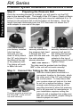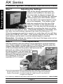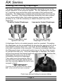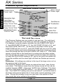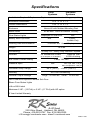
1
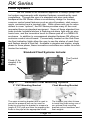
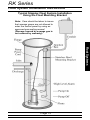
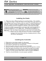
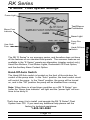
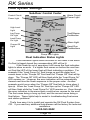
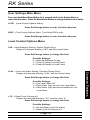
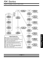
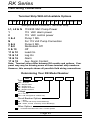
Serious Products for Serious Contractors!
User’s Manual
RK Series
Table of Contents
Pressure Systems
About RK Series Pressure Systems...................................p 3
Pressure System Installation Instructions...........................p 4 - 8
Additional Parts the Installer will need...................p 4
Pressure Bell Mounting Options............................ p 4
Typical Pressure System Installation Drawing.......p 5
Step By Step Installation........................................p 6 - 8
Seating the Rolling Diaphragm...........................................p 9
Adjusting Pressure Systems Level Settings........................p 10
Pressure System Special Features.....................................p 11
Float Systems
About RK Series Float Systems....................................... p 12
Float Mounting Options........................................p 12
Float System Installation Instructions...............................p 13-14
Typical Float System Installation Drawing...........p 13
Installing the Floats..............................................p 14
Installing the Controller........................................ p 14
RK “E Series” Operation...................................................p 15
Standard Float System Operation.....................................p 16
Features Common to Float and Pressure Systems
Alternation & Lag Delay on Duplex Controllers.................p 17
Hand Run Buttons.............................................................p 17
Redundant Off Float Option..............................................p 17
Audible Alarm Circuitry......................................................p 17
Blown Fuse Indicators.......................................................p 17
Digital Display Center........................................................p 18-21
Field Installation....................................................p 18
Display Menu Fields.............................................p 18
User Settings Main Menu.....................................p 19
Level Control Options Menu.................................p 19
Time Dosing Options Menu..................................p 20
Menu Flow Chart..................................................p 21
Enclosure Dimensions.......................................................p 22
Field Wiring Connections...................................................p 23
Specifications.....................................................................Back
Page 2
RK Series
Pressure Systems
Important:
We strongly suggest that you read and understand this entire manual
before installation. Proper installation will ensure trouble free operation of
the system.
Standard Pressure Systems Include:
The Control
Panel
The Patented
Pressure Bell
50 Feet of
1/4” Tubing
Page 3
Pressure Systems
The RK Series pressure systems are an innovative and economical solution for today’s level control requirements. Using our proprietary
pressure bell these ground breaking liquid level systems allow the user to
change all settings and adjustments outside of confined space with no
electrical level system components in wet areas, no cords to tangle or
adjust, no mercury, no mechanical switches to fail, no probes to corrode,
and no venting required.
The RK Series pressure systems combine the features of a pressure transducer, a pump controller with remote level settings and manual
test / run switches, as well as battery backed up audible alarms. The
duplex systems also include built in alternation, ten second lag pump
delay, and separate lag pump on level setting. Because the pressure
systems use the proprietary pressure bell to operate, they exceed intrinsically safe Class 1, Division 1 standards. The pressure bell transmits a
pressure only signal to the controller so no voltage from the level sensing
device enters the wet well. As the water level rises in the basin, pressure
is created in the pressure bell sending an air only signal to the controller.
The higher the level in the basin gets, the more pressure that is created in
the pressure bell. Through the use of a control circuit board, conveniently
located on the Sub-Door, this system allows the user to adjust all settings
to precise levels, in inches, by simply turning a knob.
RK Series
Pressure Systems
Pressure System Installation Instructions
The Installer Will Also Need:
(For Mounting Bracket Installation ONLY)
A length of 2” PVC pipe long enough
to reach the bottom of the basin
A 2” Male Adaptor
Step 1:
Available Pressure Bell Mounting Options
Tether Kit
Mounting Bracket
When using the mounting bracket to
install the pressure bell, start by placing the bracket against the tank wall
and mark the holes for the anchors.
Drill the holes in the side of the tank
and fasten the bracket to the tank.
The bracket should be mounted near
the top of the tank with access from
the manhole cover.
When using the tether kit simply slide
the 8 lb donut over the top to the pressure bell and thread the nipple into the
pressure bell. Then suspend the bell
by securing one end of the provided
poly rope to the bolt on the top of the
nipple and secure the other end of the
rope near the top of the basin with
access from the manhole cover. Top
mount eyebolt is provided by the
installer.
Page 4
RK Series
Pressure System Installation Instructions Contd
Note: Care should be taken to insure
that sewage gases are not allowed to
enter the control panel by using an
approved gas sealing means!
(Damage caused by sewage gas is
not covered by warranty).
Page 5
Pressure Systems
Typical Simplex Pressure System Installation
Pressure Systems
RK Series
Pressure System Installation Instructions Contd
Step 2:
Preparing the Pressure Bell
Once the mounting bracket is installed, you will need to cut the PVC
pipe to the desired length. The length of the PVC pipe = Depth of Basin
minus 14 inches (for the pressure bell) and minus an additional 6 to 12
inches (so the pressure bell is off the bottom of the basin). Once the
length has been determined and the PVC has been cut attach the 2”
male adaptor to one end of the pipe.
If for some reason
your factory installed
tube has been
removed you will
need to firmly attach
the 1/4” poly tubing to
the fitting at the top
of the pressure bell.
The tubing will push
in 5/8 of an inch.
With the tubing
securely attached to
the pressure bell, feed
it through the PVC
pipe from the side with
the male adaptor
already attached.
*IMPORTANT!
Finally, with the tubing
securely fastened to the
pressure bell and all
the tubing fed through
the pipe, thread the
adaptor to the top of
the pressure bell (Hand
Tighten Only!).
The tube must be pushed into the fitting
5/8” or the unit will not work correctly!
Step 3: Connect the Tubing to the Control Panel
*IMPORTANT*
The tube must be pushed into
the fitting 5/8” or the unit will
not work correctly!
With the control panel mounted in a
convenient location to the basin, attach
the other end of the 1/4” poly tubing to
the control panel. To help insure that
your system does not leak air it is best
to not cut or splice the tubing. Leave
enough extra tubing coiled up at the
mounting bracket to allow the pressure
bell to be removed for maintenance. If
your installation requires cutting the
tubing to exit a junction box make sure
that you use the RKCF coupler fitting to
insure a proper air seal!
Page 6
RK Series
Pressure System Installation Instructions Contd
Installing the Pressure Bell
Step 5:
Installing the Controller
Step 6:
Installing Battery Backup
With all the 1/4” tubing connected,
you will need to remove the “Do Not
Push or Pull the Diaphram” sticker
from the bottom of the pressure bell.
Do not push the bottom of the pressure bell, but feel to make sure the
rubber is tight against the cup. If it is
not, refer to the section entitled
“Seating the Rolling Diaphram” (After
Step 7) before continuing. Also,
make sure that all tubing is connected between the pressure bell and
the control panel before submersing the bell in liquid. Note: Should the
tubing become disconnected while the pressure bell is in the liquid you
will need to pump the station down manually before reconnecting the
pressure tubing. If there is an air leak or the diaphram is not seated
properly the system will not give an accurate measurement. The pressure bell can be mounted at any height off of the bottom of the basin
that you desire. Remember that the lowest you will be able to measure
will be at the top surface of the large union nut on the pressure bell.
1.
2.
3.
4.
5.
Determine a mounting location for the panel.
Determine the location of the conduit(s) coming into the panel.
Drill holes in the panel for conduit entry.
Mount the panel using the provided mounting feet.
Bring the pressure tube and power wires into the panel through the
conduit.
6. Wire the panel according to the schematic included in the panel.
7. Check installation by turning power on and manually running up the
water level to test for proper installation.
8. Test the unit periodically to ensure proper operation.
The alarm circuitry in the pressure systems
is 9-volt battery backed-up. The 9-volt
power will sound the audible alarm and
light the red alarm light on the front of the
Sub-Door. It will not light the flashing red
light on the top of the panel. To install the
9-volt battery open the Sub-Door and insert
the battery into the clip on the circuit board.
Page 7
Pressure Systems
Step 4:
Pressure Systems
RK Series
Pressure System Installation Instructions Contd
Step 7:
Adjusting the Settings
Step 8:
Fine Adjustments
With all the tubing connected and the
pressure bell installed in the basin you
are now ready to adjust your level settings. To adjust the ON and OFF settings
of the pump(s) and HIGH LEVEL alarm,
turn the dials to the desired depth in inches on the faceplate. The inches on the
dials are measured from the top of the
union nut surface on the pressure bell
upward. You can also turn the pumps on
manually by pushing the hand run button
once to run and again to stop. (This button switches to momentary contact after low level setting is passed See Hand Run Buttons p.17).
When the pumps are running in normal run mode they will run until they
reach the PUMP(S) OFF mark. If the pumps need to be run further, the
hand buttons can be held in until the desired depth is reached.
Remember: All settings are relative to the top of the large union nut on
the pressure bell in the basin.
With the pressure units the settings can be adjusted to a precise measurement. Using a digital volt meter, set on DC-Volt setting. Carefully, place the
negative lead (black) onto the GND test point on the back
of the circuit board and the positive lead (red) onto the
test point you wish to view (as shown in
the picture below). The volt meter will
give a reading in inches by moving the
decimal to the right one number.
So a reading of 1.514 is the
equivalent of 15.14 inches.
Choose the appropriate test point depending upon what type of panel you have.
Simplex (One pump) - Provides Pump Off, Pump On & High Level setpionts
Duplex (Two pumps) - Provides Pumps Off, Lead Pump On, Lag Pump On
& High Level Setpoints
If you need any additional help please call the factory for technical assistance. 1-800-363-5842
Page 8
RK Series
Seating the Rolling Diaphragm
Air Gap between Rubber
Diaphragm & Push Cup
Rubber Diaphragm is tight
against Push Cup
A diaphragm that is not seated properly must be reseated. Reseating
the diaphragm can be accomplished by plunging the pressure bell into a
liquid depth of about three feet. This must be done without the pressure tube connected to the controller. (To remove a pressure tube from
the fitting push down on the small center ring on the top of the connector and pull the tube out). Once the diaphragm is reseated, the rubber
will be snug around the internal push-cup and when lightly touching the
diaphragm the push-cup can be felt
immediately behind the diaphragm.
Then make sure the pressure tube is
reconnected to both the pressure bell
and the controller before the bell is submerged in liquid.
*IMPORTANT*
The tube must be pushed into the fittings
5/8” or the unit will not work correctly!
Push here and pull tubing to remove tubing
Page 9
Pressure Systems
The proper operation of the rolling diaphragm assembly is key for the
proper operation of the pressure system. For the diaphragm to be seated, it must be snug around the push-cup inside of the pressure bell
assembly. The diaphragm is seated and protected when sent from the
factory. However, if the rolling diaphragm assembly has been pushed
up by some method other than water pressure (someone manually
pushing on it), it will be necessary to reseat the push cup in the
diaphragm.
Properly Seated Diaphragm
Improperly Seated Diaphragm
RK Series
Pressure System Adjustments
Pressure Systems
Control Circuit
Power Light
Sub-Door Control Center
Adjustable High
Level Alarm
Adjustable Lag
Pump “Cut-In” Dial
Alarm Circuit
Power Light
Test/Silence
Pushbutton
Adjustable Lead
Pump “Cut-In” Dial
Alarm Light
Adjustable Pumps
“Cut-Out” Dial
Pump Run Lights
The Level Set Points
Hand Run
Pushbuttons
The Pressure Systems are very simple to set and use. For each level
setting you turn the dial to the level you want the controller to switch at.
For example, using the duplex controller turn the PUMPS OFF dial to
4”, the LEAD PUMP ON dial to 12”, the LAG PUMP ON dial to 24”, and
the HIGH LEVEL dial to 36”. As the level in the basin comes up the
LEAD PUMP will turn on at 12”, and LAG PUMP will turn on at 24” (with
a 10 second delay), and as the liquid level in the basin is being pumped
down the pumps will shut off at the PUMPS OFF level of 4”. If for some
reason a pump fails or the liquid level is coming into the basin quicker
than the pumps can remove it, the liquid level in the basin will eventually reach the HIGH LEVEL setting of 36” and at this point the system will
sound the audible and the alarm light will flash two flashes per second
(fast).
Remember: All settings are relative to the top of the large union nut on
the pressure bell in the basin.
The Pressure Systems also contain an internal low level / loss of pressure alarm. This feature comes from the factory turned off, but can be
enabled through a DDC. (See page 19 DDC User Settings) This alarm
will occur if the liquid level falls below 3”, or if the system air pressure is
lost. The PUMP OFF setting can not be set below 4” so that the level in
the basin will never be below the 3” level under normal operating conditions. Should this situation occur the user has a few options of how
they would like to be notified of the problem.
Page 10
RK Series
Pressure System Special Features
Note 1: If the system losses pressure the most likely reasons are:
These level settings are designed to work similar to a float system. On
the simplex system if the PUMP ON setting is set below the PUMP OFF
setting, the controller will turn the PUMP RUN light & a pump run contact both on and off at the PUMP OFF level setting. Similarly the duplex
controller will turn on and off at the PUMPS OFF setting if the LEAD
PUMP ON setting is below the PUMPS OFF setting. The HIGH LEVEL
setting can be at any depth above your PUMP(S) OFF setting so that
you can trigger an alarm below your LAG PUMP ON setting.
Battery Backed Up Alarm & Aux. Contact
The battery provides power only to the alarm circuit when the normal
120VAC power fails. This would make an alarm condition available
even when the power is off. The battery power is not used while the
normal 120 VAC power is available.
The battery back-up maintains the alarm circuit so the alarm LED and
alarm audible will work during a power outage. It does NOT power the
alarm beacon.
To test the battery, use the following steps: First, remove the 120VAC
power when the PUMP RUN light is not on. Next, press the TEST
pushbutton. Look to see that the ALARM LED on the sub-door is on
and the audible should alarm. If you have a multimeter handy you can
also check for continuity across the auxiliary alarm contacts when the
alarm button is pushed. If the LED does not come on, or the audible
does not sound then the battery should be replaced.
Note: Auxiliary Alarm contacts are optional and close during high level
alarm then open when alarm condition goes away or when panel is
silenced.
To Maintain reliable battery backed-up service we suggest you replace
the battery once a year.
Note: If long or frequent power outages occur the battery may need to be
replaced more often.
Page 11
Pressure Systems
1) Tubing is not fully inserted into quick connectors
2) Tubing in quick connectors is not cleanly and squarely cut on the end
3) The diaphragm on the pressure bell has somehow been punctured
4) The tubing has been cut somewhere and is leaking air
5) No liquid in the basin - Possible siphon condition
Note 2: The pressure bell works by measuring the total amount of liquid above the
diaphram. If the tube is disconnected while the bell is submerged and
then reconnected that level now becomes zero (0) inches of liquid. The
system will then need to be recalibrated by either manually pumping down
the liquid using the hand run button(s) or by lifting the pressure bell out of
the basin BEFORE reconnecting the pressure tube.
Float Systems
RK Series
Float Systems
The RK Series is an innovative approach to today’s pump control system requirements with standard features unmatched by most
competitors. Through the use of a standard sub-door and raised
backpanel the RK Series offers a revolutionary design for housing
common control panel features such as circuit breakers, start components, contactors and a terminal strip. While others ask you for more
dollars to cover “options”, the RK Series provides many of the most
requested items as standard equipment. Some of these standard features include: lockable latches, a flashing red alarm light with an electronic horn, and the innovative touch to silence pad all in a NEMA 4X
enclosure. In addition to unsurpassed standard features RK offers an
exclusive control circuit board. Conveniently located on the Sub-Door
the float indication lights allow the user to see the status of each float
and flashes should a float fail. Available in simplex and duplex, single
phase to three phase, these innovative controllers are certain to revolutionize the industry.
Standard Float Systems Include:
The Control
Panel
Floats (3 for
simplex 4 for
duplex)
Step 1:
Available Float Mounting Options
2” PVC Mounting Bracket
The same mounting bracket that is used to
mount the pressure bell can be used for
floats by mounting the bracket to suspend a
length of PVC pipe and then tie wrapping the
floats to the pipe at the appropriate levels.
Page 12
Float Mounting Bracket
The installer may also choose
to install the floats using one of
our optional float mounting
brackets w/cord snubbers and
float weights.
RK Series
Float System Installation Instructions
Typical Simplex Float System Installation
Using the Float Mounting Bracket
Note: Care should be taken to insure
that sewage gases are not allowed to
enter the control panel by using an
approved gas sealing means!
(Damage caused by sewage gas is
not covered by warranty).
Float Systems
Page 13
Float Systems
RK Series
Float System Installation Instructions Contd
Installing the Floats
1. There are many different options to mounting floats. The installer
can simply tie wrap or strap the floats to the pump discharge pipe at the
appropriate levels using a heavy duty tie wrap or a clamp designed for
that use. Floats can also be installed using a float mounting bracket
w/cord snubbers and float weights as shown on the previous page.
Finally the installer can purchase a pressure bell mounting bracket to
suspend a length of 2” PVC pipe from. This allows the installer to
mount the floats the same as they would to the pump discharge pipe.
Warning: 1. Do not install a float switch in direct line of incoming liquid.
2. Make sure you leave at least 3.5 inches of tether length
between the actual float and the clamping device to allow
the float to tip properly.
1.
2.
3.
4.
5.
6.
7.
Installing the Controller
Determine a mounting location for the panel.
Determine the location of the conduit(s) coming in to the panel.
Drill holes in the panel for conduit entry.
Mount the panel using the provided mounting feet.
Bring the float and power wires into the panel through the conduit.
Wire the panel according to the schematic included in the panel.
Check installation by turning power on and manually tipping the
floats or running up the water level to test for proper installation.
8. Test the unit periodically to ensure proper operation.
Page 14
RK Series
“E Series” Float System Settings
Power Light
Test/Silence
Pushbutton
Blown Fuse
Indicator
Alarm Light
Pump Run
Light
User Safe
Fuse
The RK “E Series” is our economy series, and therefore does not have
all the features of our standard float panels. The common features not
available in the “E Series” panels are alternation (simplex control only),
Hand Run Buttons, Float Status Lights, Redundant Off Float Option,
and the Auxiliary Alarm Contact Option.
Hand-Off-Auto Switch
The Hand-Off-Auto switch is located on the front of the sub-door for
control of the pump state. In the “Auto” position, the level control circuit
will control the pump. In the “Hand” position, the pump will be turned
on, and in the “Off” position the pump will be disabled from running.
Note: When there is a fuse blown condition on a RK “E Series” controller the “blown fuse indicator” will light and the “power light” will continue to be dimly lit.
That’s how easy it is to install and operate the RK “E Series” Float
System from CSI. If you need any additional help please call the
factory for technical assistance.
1-800-363-5842
Page 15
Float Systems
Hand-Off-Auto
Switch
Float Systems
RK Series
Float System Settings
Control Circuit
Power Light
Sub-Door Control Center
High Level
Light
Alarm Circuit
Power Light
Test/Silence
Pushbutton
Lag Pump
On Light
Lead Pump
On Light
Alarm Light
Pumps Off
Light
Hand Run
Pushbuttons
Pump Run Lights
Float Indication Status Lights
Float indication lights show the status of the floats in the basin.
If a float is tipped closed the corresponding LED will be lit.
If the floats tip out of sequence it will cause the float indication
lights to show an error. If a higher float comes on before the next lowest float the LED of the lower float will flash indicating a problem. For
example if the “Lead Pump On” float hangs up and the water level
comes down to the “Pumps Off” float level the “Pumps Off” float will tip
down. The “Pumps Off” LED will then flash while the “Lead Pump On”
LED remains on. However, the error indication will be automatically
cleared next time the floats sequence in the proper order. Another
example would occur when the “Pumps Off” float fails to close when it
tips up. When the “Lead Pump On” float tips up the “Pumps Off” LED
will then flash while the “Lead Pump On” LED remains on. Even though
the error indication is the same there could be two causes for the error.
The first cause being a hung up float, and the second cause being a
float failure. These lights help to assist in troubleshooting float errors
and station problems.
That’s how easy it is to install and operate the RK Float System from
CSI. If you need any additional help please call the factory for technical
assistance.
1-800-363-5842
Page 16
RK Series
RK Series Features
Features Common to Both Pressure & Float Systems
Alternation and Lag Delay on the Duplex Controllers
On the duplex controller the float indications are labeled LEAD and LAG
because there is a built in alternator in the controller. The alternator
cycles which pump is the lead pump after each PUMP RUN cycle. The
non-adjustable delay causes the lag pump to wait ten seconds before
turning on after the lead pump has turned on. This is useful during a
power outage when the liquid level may reach the lag pump setting.
The lead pump will turn on when power is restored and the lag pump
will turn on ten seconds later.
Hand Run Buttons
RK
(HAND)
pushbuttons
for the
starters
RK panels
panelsinclude
includepush-to-run
push-to-run
(HAND)
pushbuttons
for motor
the motor
output
and
a push-to-test
(TEST) pushbutton
for the alarmfor
output
accessible
starters
output
and a push-to-test
(TEST) pushbutton
the alarm
outon
sub-door.on
The
push-to-run
pushbuttons
toggle their
respective
putthe
accessible
the
sub-door.(HAND)
The push-to-run
(HAND)
pushbuttons
outputs
off and
on each time
pushed
under
operation.
However,
to
toggle their
respective
outputs
off and
onnormal
each time
pushed
under norprotect
the
pumps
should
the
sump
go
below
Pump(s)
Off
float
(Float
panels)
mal operation. However, to protect the pumps should the sump go
or the Low Level point (Pressure panels), the HAND pushbuttons revert to
below Pump(s) Off level, the HAND pushbuttons revert to momentary
momentary contact and must be held down to maintain its respective output
contact and must be held down to maintain its respective output on.
on. This is a safety feature that keeps the pumps from running dry.
This is a safety feature that keeps the pumps from running dry.
Redundant Off Float Option
Note: “Hand Run Buttons” (above) describes momentary contact mode.
Audible Alarm Circuitry
RK panels come standard with an audible piezo alarm (95 db +/-) and
the exclusive side mounted “Touch to Silence” pad (patents pending).
With this feature the user is able to silence the audible by simply touching the decal on the side of the enclosure.
Blown Fuse Indicators
These lights are located above the fuses on the sub-door. If a fuse is
blown the indicator above the blown fuse will light up and the power
light on the sub-door control center for that circuit will be off. However,
if the power light is off and the blown fuse light is not lit then that circuit
is not getting any power.
Page 17
Common Features
The redundant off float option reassures that the pump(s) will not run
dry. If your panel has this option the terminal strip will include numbers
7 & 8. To use the redundant off option connect a normally open float
switch to these terminals, otherwise install a jumper across terminals 7
& 8 if you do not wish to use this feature. When the float is in the open
position the pumps will not be able to run except by using the hand run
push buttons in momentary contact mode.
Common Features
RK Series
Digital Display Center (DDC)
Make Sure Power is OFF before Installing DDC!
Installation
With Future Expansion in Mind, Every RK Panel has
a Removable Expansion Board Face Plate to Add a
DDC if it is not factory installed or to Upgrade a DDC
to a model with more features. To install just remove
the faceplate from above the control center on the
sub-door (or remove the old DDC if you are upgrading) and insert the DDC module from the back of the
sub-door. Next, screw in the four corner screws.
With the power off attach the ribbon from the DDC
module to the control board. After everything is
installed turn the power on. It may take up to 10 seconds for the circuit boards to complete the program
update. Once the circuit boards have completed the
program update normal operation will begin.
Note: RKE boards cannot update through the DDC.
Installation Screws
Main Menu
dEPH
Removable Face Plate
Back of DDC Module
Connecting Ribbon
Menu/Enter
Button
Set/Change
Button
Display Menu Fields
Press Menu/Enter Button to change between menu fields
dEPH - (Depth, Pressure type panels only):
Reads out liquid level in inches. (Max value: 49.99”)
Et. # - (Elapsed Time, # is Pump number (1 or 2)):
Reads out the total elapsed run time of the corresponding pump.
Press Set/Change button to alternate between
hours and minutes & seconds
CC.# - (Cycle Counter, # is Pump number (1 or 2)):
Reads out the number of cycles the corresponding pump has
run. (Max Value: 9999)
F1tr - (Field 1 Timer, Time Dose DDCs only):
Reads out the remaining time in the current time cycle. If the
pump(s) are running then it indicates the time remaining until the
pump(s) shut off. If the pump(s) are off then it indicates time
remaining until the pump(s) are enabled tol run again.
Page 18
RK Series
User Settings Main Menu
Press and hold Menu/Enter Button for 3 seconds while in the Display Menu to
enter into this menu. Press the Menu/Enter Button to change between menu fields.
LCOP - (Level Control Options Menu):
Press Set/Change button to enter into this sub-menu.
tDOP - (Time Dosing Options Menu, Time Dose DDCs only):
Press Set/Change button to enter into this sub-menu.
Level Control Options Menu
LSS - (Lead Selection Setting, Duplex Panels Only):
Diplay will alternate showing “LSS” and the current Value.
Press Set/Change button to change this field.
Possible Settings:
0 = Alternate Between Pumps
1 = Pump #1 Always is Lead Pump
2 = Pump #2 Always is Lead Pump
Press Set/Change button to change this field.
Possible Settings:
0 = Low Level Alarm Off
1 = Flash Alarm Light only for Low Level Alarm
2 = Flash Alarm Light and sound audible for Low
Level Alarm
r CC - (Reset Cycle Counter(s))
Display will alternate showing “r CC” and the value “0.”
Press Set/Change button to change this field.
Possible Settings:
0 = Do Not Reset Cycle Counter(s)
1 = Reset Cycle Counter(s) to 0
Page 19
Common Features
LLAL - (Low Level Alarm Setting, Pressure Panels Only):
Display will alternate showing “LLAL” and the current value.
Common Features
RK Series
Time Dosing Options Menu
F1t1 - (Field 1 Time 1 (Pump Enable Time Setting))
Display will alternate showing “F1t1” and the current value. Time shown
is in [Minutes : Seconds] (Maximum time setting is 99:59)
Press Set/Change button to change this field.
F1t2 - (Field 1 Time 2 (Pump Disable Time Setting))
Display will alternate showing “F1t2” and the current value. Time shown
is in [Hours : Minutes] (Maximum time setting is 99:59)
Press Set/Change button to change this field.
ALOr - (Alarm / Override Function):
Diplay will alternate showing “ALOr” and the current value.
Press Set/Change button to change this field.
Possible Settings, Simplex:
(What the High Level set point will do)
0 = Override the Pump Disable Timer and Alarm with selected
Time Delay (see HLtd setting). A warning will sound and
flash the alarm light to indicate the panel is in Override
mode. This can be silenced. It will be cleared after the
Disable timer times out.
1 = Only Override the Pump Disable Timer without any alarms.
2 = Only Sound High Level Alarm without any delays.
Possible Settings, Duplex:
(What the Lag (override) set point will do)
0 = Override Pump Disable Timer. A warning will sound and
flash the alarm light to indicate the panel is in Override
mode. This can be silenced. It will be cleared after the
Disable timer times out.
1 = Override the Pump Disable Timer. No warning will sound.
2 = Override function is disabled. Lag float input or setpoint is ignored.
HLtd - (High Level Time Delay, Simplex Panels Only):
Diplay will alternate showing “HLtd” and the current value. The High
Level Alarm will delay according to the set time. If the the fluid level is
above the High Level set point for this length of time without interruption
the alarm will begin to sound. Time shown is in [Minutes :
Seconds] (Maximum time setting is 99:59)
Press Set/Change button to change this field.
Page 20
RK Series
Digital Display Center Flow Chart
Common Features
Page 21
Common Features
RK Series
Enclosure Dimensions
7.625”
15”
13”
12”
7.5”
Page 22
RK Series
Field Wiring Connections
Terminal Strip With All Available Options
L1 L2 N 1 2 3 4 N 5 6 7 8 9 10 11 12 13 14 15 16 17 18
Sample RKDF230ACB+ Terminal Strip
L1, L2 & N
1
2
3&4
N
5&6
7&8
9 & 10
11 & 12
13 & 14
15 & 16
17 & 18
115/230 VAC Pump Power
115 VAC alarm power
115 VAC control power
Pump 1 Mtr.
For 115 Volt Pump Connection
Pump 2 Mtr.
Redundant Off
Off
Lead On
Lag On
Alarm
Aux. Alarm Contact
Note: Termianl strips differ between RK models and options. Your
panel may may be missing some of these terminal strip numbers.
However, this example shows all possible field wiring connections.
Type
RK
ESF = E Series
SF = Simplex Float
DF = Duplex Float
SP = Simplex Pressure
DP = Duplex Pressure
Voltage
115 = 115 Volt
230 = 230 Volt (optional 115/230 Volt)
Circuit Breaker Options
___ = None
CB = Control and Pump Circuit Breaker(s)
ACB = Alarm, Control, and Pump Circuit Breaker(s)
Other Options
+ = Includes Redundant Off & Aux. Contact Options
Page 23
Common Features
Determining Your RK Model Number
Specifications
Available in Simplex & Duplex
Enclosure Dimensions
Overall Dimensions
Enclosure
Alarm Piezo
Float Status Lights
Battery Back-Up Alarm
Flashing Red Alarm Beacon
Weight
Contactor(s)
Includes:
Aux. Alarm Contact Rating
Pressure
Systems
Float
Systems
Duplex Includes alternator & lag pump delay
12.5” X 12” X 7.5”
14.5” X 12” X 7.5”
Nema 4X with Molded Mounting Feet
95 db with “Touch to Silence” circuitry
Displayed on Sub-Door
N/A
N/A
9 VDC
Audible Only
Provides 360° Visual Display
10.8 lbs.
25 amp “DP” Heavy Duty Definite Purpose
20’ Mechanical Floats
Pressure Bell
& 50ft of tubing
(3 for simplex, 4 for Duplex)
5 amp 120 VAC
Pressure Input
N/A
Min: 0 psi Max: 1.73 psi
Max Overpressure: 10.8 psi
Controller Temp. Range
-40°F (-40°C) - +185°F (+85°C)
Terminal Torque Ratings
Large - 35 inch lbs., Small - 12 inch lbs.
Humidity
95% non-condensing
Non-Conductive Injection Molded Sub-Door
Blown Fuse Status Lights
cULus 508 Listed
Maximum 2 HP - (12 FLA) or 3 HP - (17 FLA) with HD option
3 Year Limited Warranty
220 Ohio Street · Ashland, OH 44805
Phone: 419-281-5767 Fax: 419-289-2535
[email protected]
• www.CSIcontrols.com
[email protected]
· www.chandlersystemsinc.com
RKMan 12/06