1
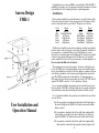
!
Congratulations on your new FMR-1 converted radio. With the FMR-1
installed in your radio you will experience unrivaled performance, features
and reliability all while retaining the radios original appearance.
Aurora Design
FMR-1
Installation:
Before starting installation you should remove one of the battery cables.
Your radio came with a short 12 pin wiring harness. This harness will be
used to connect the radio to your vehicle. The pinout is as follows:
Color
Signal
Red
Ignition
Blue
Switched Bat Out
White
Left Front+
Grey
Right Front+
Green
Left Rear+
Violet
Right Rear+ Color
Signal
Black
Ground
Orange
Dial Lamp
White/Black
Left FrontGrey/Black
Right FrontGreen/Black
Left RearViolet/Black
Right Rear-
The Red wire should be connected to an Ignition switched circuit that is
fused as shown in the Configuration section of this manual. It should not
be connected to a continuous battery circuit. The Black wire can be
attached to a convenient point on the dashboard. The Orange wire should
connect to the original dash lamp circuit. The Blue wire is a switched
power output that can be used for power antennas, external amplifiers, etc.
Do not connect the Blue wire to battery!
The remaining wires are for the speakers. To achieve such high power
levels, the FMR-1 uses a bridged amplifier design where neither speaker
lead is ground. Both wires actively drive the speaker so speakers with one
side already grounded as used in some original applications must not be
used. The FMR-1 performs best with speakers of 4 ohm impedance, a
SPL rating of at least 90 and a power rating of at least 30W (50W for full
output). The FMR-1 can drive 1, 2 or 4 speakers as follows:
For a 1 speaker installation the speaker can be connected to any one of
the four outputs. The FMR-1 will detect that only one speaker is attached
and enable mono mode while disabling the balance and fader controls.
For a 2 speaker installation, the speakers can be attached in one of three
ways as follows:
User Installation and
Operation Manual
!
1) If the two speakers are attached to either the front left/right pair or
the rear left/right pair the FMR-1 will enable stereo mode and the
balance control.
2) If one speaker is attached to the left or right front output and the
other speakers is attached to the same channel (left or right) rear
output, the FMR-1 will enable mono mode and the fader control.
3) If one speaker is attached to the left or right front output and the
other speakers is attached to the opposite channel (right or left)
2
!
rear output, the FMR-1 will enable stereo mode and the fader
control.
For a 4 speaker installation all the speaker outputs will be used and the
FMR-1 will enable stereo, balance and fader controls.
Note: when attaching a speaker output to an external amplifier, a 150
ohm 1 watt resistor needs to be connected across the output to tell the
FMR-1 an external amplifier is attached to that output.
All unused wires should be taped up so they can’t short out. The radio
can now be mounted back into the vehicle as original and connected to the
new wiring harness. Reattach the battery cable. Installation is now
complete.
Operation:
Your converted radio will operate as before but with new performance
and features.
LED: If your radio has a front panel status LED installed, it will display
the current operating mode as for AM, FM, Bluetooth, Auxiliary and
Errors. The color of the LED for each mode will be as shown in the
Configuration section of this manual.
Mode Select: Mode selection (AM, FM, Aux) is accomplished in
different ways depending on your radio. In the following description,
power cycling refers to quickly switching the radio off and back on.
Each time this is done the radio with change to the next mode. The radio
will always return to the last mode selected when first turned on.
If your radio has an AM/FM band switch, it will work as normal,
otherwise AM/FM selection is done by power cycling.
The Auxiliary Input is selected by either tuning to the low end of the
dial, automatically when a signal is sensed (VOX), or power switch
cycling. Refer to the Configuration portion of this manual for
information on how your radio was configured.
Balance/Fader: If your radio has balance/fader controls they will
operate as before. If your radio does not have balance/fader controls, the
FMR-1 enables virtual controls.
Virtual Balance: Quickly twist the tone control back and forth twice
to the left. The tone control temporarily becomes the balance control.
A tone will alternate between the left and right channels to verify
you have entered the virtual balance control. You may adjust the
balance for as long as you wish. When finished, the FMR-1 waits a
few seconds and then signifies that the setting was accepted by
playing a tone. This setting is retained until it the next time it is
changed.
3!
Virtual Fader: Quickly twist the tone control back and forth twice
to the right. The tone control temporarily becomes the fader control.
A tone will alternate between the front and rear channels to verify
you have entered the virtual fader control. You may adjust the fader
for as long as you wish. When finished, the FMR-1 waits a few
seconds and then signifies that the setting was accepted by playing a
tone. This setting is retained until the next time it is changed.
Loudness Contouring: This is a method of adjusting or contouring the
audio spectrum to match that of the human ear. This should normally be
enabled as it will make the audio sound more natural at all volume
levels. To enable Loudness Contouring, quickly twist the tone control
back and forth three times to the left. To disable Loudness Contouring
and provide a flat frequency response, quickly twist the tone control
back and forth three times to the right. The FMR-1 signifies that the
setting was accepted by playing a tone.
Tone Switch: If your radio has a tone switch rather than a tone control it
may have been configured to select between volume and tone functions
on the main volume control. In one position of the tone switch, the
volume control will function as normal. In the other position of the tone
switch it will function as the tone control with full compatibility with the
virtual controls as described above. When you switch from volume to
tone, the FMR-1 will hold the volume steady until you return to the
volume position of the tone switch. Since it is possible the volume
control could now be set to a very high volume depending on where it
was left after making adjustments to the tone and virtual controls, the
FMR-1 will beep once to alert you of this condition, and the volume
control will need to be lowered to at least the previous level before it
will start operating normally again. Also if the tone switch is set to the
tone position when the radio is first turned on, the volume will be at a
safe, preset level so that it will not damage the speakers.
Tuning: Your radio will tune as before including pushbuttons and
automatic Signal Seeking operation. Pushbuttons can be set for an AM
or FM station (radio must be in correct band mode for button). Signal
Seeking radios like the Wonderbar® and Town & Country will operate
as before including sensitivity (Town/Country) controls.
Line Out: Optional Line Out jacks may have been added to your radio if
requested. The five outputs (front/rear pair and subwoofer) can be
attached to an outboard amplifier. These outputs are post pre-amp and
are affected by the controls on the radio.
Troubleshooting:
Low Power: If the voltage to the radio drops to low for normal
operation, the front panel LED will alternate between green and red and
no audio will be heard until this situation is corrected.
4
!
No Sound: Make sure the radio is getting power. Check all fuses and
wiring. Make sure speakers are properly connected and in good working
order.
Weak/Noisy Reception: Make sure the antenna is connected to the
radio and in good working order. The cable for the antenna can become
damaged. Check for continuity between the center pin of the connector
and the antenna mast. Also check for shorts between the center pin and
the outer shield.
The FMR-1 uses sophisticated noise blankers to reduce or eliminate
most engine/generator noise. If engine or generator noise is still present,
investigate the cause of this noise, i.e. spark plugs and wires, generator/
alternator suppression condensers etc.
PowerOnDiagnostics: Each time the radio is powered on it uses a
sophisticated method to check the speaker outputs for problems. If
found, the specific speaker channel is disabled and the error is reported
on the front panel LED (if installed). The LED will flash a pattern
similar to that used by the automotive ODB standard. The pattern
consists of a number of flashes indicating which speaker followed by a
short pause, then another set of flashes indicating the specific problem. If
multiple faults are found, each of these patterns will be followed by a
long pause and the next fault will be displayed.
First Group of Flashes
1 - Left Front Speaker
2 - Right Front Speaker
3 - Left Rear Speaker
4 - Right Rear Speaker
Second Group of Flashes
1 - Short to Ground
2 - Short to Battery
3 - Line shorted together
4 - Internal Error
Configuration:
☐
Tone Control - Original
☐
Tone Control - External control
☐
Tone Control - Using tone switch and volume control
☐
Balance Control - Original
☐
Balance Control - External control
☐
Balance Control - Virtual
☐
Fader Control - Original
☐
Fader Control - External control
☐
Fader Control - Virtual
☐
AM/FM switching - Original
☐
AM/FM switching - Power cycling
☐
☐
☐
☐
Aux Input selection - Tune to left side of dial
Aux Input selection - Signal sensing (VOX)
Aux input selection - Power cycling
Aux input selection - External switch
☐
American channels
☐
Worldwide channels
☐
Japanese channels
Overheating: If the FMR-1 ever overheats in operation the front panel
LED (if installed) will blink slowly. No damage will occur to the radio
and it may start to lower the output power to bring the temperature back
down. This should never occur in normal operation.
☐
LED - Not Installed
☐
LED - AM:Green FM:Yellow BT:Orange AUX:Red ERR:Red
☐
LED -AM:Red FM:Orange BT:Yellow AUX:Green ERR:Green
Options:
☐
☐
☐
☐
If your radio was equipped with the BT-1 Bluetooth adapter, the
FMR-1 will automatically mute the radio and switch to the Bluetooth
input when audio is streaming or a call is received. If your radio was
equipped with a USB-1 adapter, the FMR-1 will automatically mute the
radio and switch to the USB input whenever a USB FLASH drive is
inserted. Please refer to the appropriate User Manual for complete
information.
5!
Power - 12V negative ground, fused @ 12.5A max
Power - 12V positive ground, fused @ 8A max
Power - 6V negative ground, fused @ 12.5A max
Power - 6V positive ground, fused @ 8A max
☐
Original Power lead
☐
Red wire in cable harness
☐
Original Dial lamp lead
☐
Orange Dial lamp wire in cable harness
☐
Dial lamp comes on with radio
6
!
Specifications*:
FM Receiver:
Frequency Range:
Channel Spacing:
Sensitivity:**
De-emphasis:
SNR:**
Image Rejection:** Audio Separation:**
Audio Response:**
87.5-108MHz (Worldwide except Japan)
76.0-90.0MHz (Japan)
200kHz (America’s)
100kHz (all other regions)
5.0dBµV @ 26dB SNR
75µS (America’s)
50µS (all other regions)
60dB typ
60dB typ
40dB typ
30Hz-15kHz -3dB
Date:
Job #:
AM Receiver:
Frequency Range:
Channel Spacing:
Sensitivity:**
SNR:**
Image Rejection:** Dealer Name:
530-1710 (America’s)
531-1611 (all other regions)
10kHz (America’s)
9kHz (all other regions)
30dBµV @ 26dB SNR
56dB typ
55dB typ
Audio Output:
Speaker Impedance:
Output Power:
4-32Ω
4 X 45W into 4Ω @ 14.4V max (EIAJ)
4 X 22W into 4Ω @ 14.4V 1% THD
Auxiliary Input:
Input Level:
Input Impedance:
Withstand Voltage:
-10dBV nominal level
0dBV max without clipping
~7.5KΩ
+/- 24V max
Auxiliary Outputs:
Output Level:
Frequency Response:
0dBV nominal level into 5KΩ
10Hz-20kHz -1dB into 5KΩ
*Subject to change without notice **Characterized by component manufacturer
7!
Aurora Design LLC. ©2013-15 Rev 1.7
www.tech-retro.com
8