1
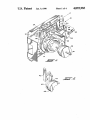
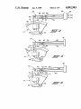
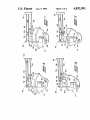
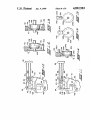
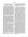
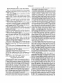
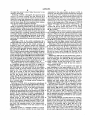
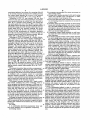
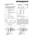
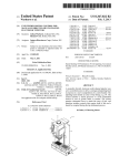
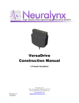
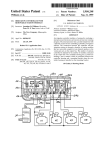
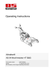
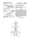
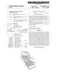
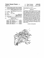
3
4,892,983
4
manner well known in the art, the details of which have
BRIEF DESCRIPTION OF THE DRAWINGS
been omitted for the sake of brevity.
Deck plate 12 has mounted thereon an insulator block
- FIG. 1 is a somewhat perspective of the program
32 which has molded therein and extending outwardly
thereform in spaced generally parallel cantilevered rela
mer/timer of the present invention with portions of the
housing removed;
tionship a plurality of stacked switch contact blades
comprising a combination line and program switch
assembly indicated generally at 34. The combination
FIG. 2 is an enlarged view of a portion of the line
switch actuator of FIG. 1;
FIG. 3 is a front view of the combined line/program
switch of FIG. 1 with the line switch actuator in the
“OFF” position and the switches in the open circuit
switch has an upper contact blade 36 which extends the
furthest distance from block 32 and which has a termi
nal portion 38 extending through the block 32 and out
wardly therefrom for electrical connection to one side
of a power line. The line switch contact blade 36 has
condition;
FIG. 4 is a view similar to FIG. 3 with the line switch
actuator in the “ON” position, the line switch closed
and the program switch open circuit;
provided on the lower face thereof a suitable button
contact 40 which is adapted for making and breaking a
FIG. 5 is a view similar to FIG. 4 with the program
cam rotated to a position closing the program switch;
FIG. 6 is a view similar to FIG. 3 and shows the line
cent the lower face of the line switch contact blade 36
switch actuator in the “OFF” position with the pro
near its free end is a line switch actuator 42 which is
gram maintaining the line switch closed;
suitably mounted on deck plate 12 for sliding movement
circuit upon movement of the blade 36. Disposed adja
FIG. 7 is a view similar to FIG. 6 with the line switch 20 in the vertical direction. Line switch actuator 42 has an
actuator in the “ON” position and the cam maintaining
inclined “cam surface 44 provided thereon which
contacts a corresponding surface 48 provided on an
the line switch closed;
FIG. 8 is a view similar to FIG. 7 with the line switch
axially movable cam member 46. Cam member 46 has a
actuator in the “ON” position and the cam rotated to a
shaft extending therefrom which is received in cam 14
position closing the program switch;
25
for axially sliding movement therein by the appliance
FIG. 9 is a view similar to FIG. 8 with the program
cam in the same position as FIG. 8 but with the line
user. Axial movement of cam member 46 is effective to
cause movement of line switch actuator 42 from the
switch actuator in the “OFF” position opening the line
position shown in solid outline in FIG. 2 to the position
shown in dashed outline. It will be understood that shaft
49 although axially moveable is engaged with cam drum
switch;
FIG. 10 is a view similar to FIG. 9 with the line
switch actuator in the “OFF” position and the cam
rotated to a position maintaining both line and program
switches in the open circuit condition;
FIG. 11 is a view similar to FIG. 10 with the cam
positioned in the same position as FIG. 10 but with the
line switch actuator the “ON” position closing the line
switch;
FIG. 12 is a view of an alternate embodiment of the
line switch actuator cam illustrated in the “OFF” posi~
tion;
FIG. 13 is a view similar to FIG. 12 showing the line
switch actuator in the “ON” position;
FIG. 14 is a view similar to FIG. 12 showing another
embodiment of the line switch actuator cam;
FIG. 15 is a right-hand view of the embodiment of 45
FIG. 14 with the line actuator cam in the “ON” posi
tion; and
FIG. 16 is a view similar to FIG. 15 with the line
switch actuator cam in the “OFF” position.
DETAILED DESCRIPTION
Referring to FIGS. 1 and 2, the programmer/timer is
indicated generally at 10 and has a housing or deck plate
14 for rotation therewith by any suitable means such as
a clutch, ?ats on shaft 49 (not shown) or other tech
nique well known in the art. '
A lower program contact blade 50 is mounted in and '
extends from insulator block 32 in cantilever arrange
ment with the free end thereof having a follower 52
thereon for contacting a level surface 15 of the cam
drum for stationary location with respect to the drum
surface as a datum from which the cam track 16 is lo
cated. The program blade 50 has an electrical contact
54 disposed on the upper surface thereof with reference
to lower program contact blade 50 has a connector
portion 52 thereof extending through insulator block 32
and adapted for electrical connection to various desired
appliance load functions.
An intermediate program blade 58 is disposed be
tween upper blade 36 and the lower blade 50, the inter
mediate blade extending in cantilever from insulator
block 32 in spaced generally parallel relationship with
blades 36 and 50. Intermediate blade 58 has a cam fol
lower 60 provided at the free end thereof which fol
lower is self-biased by the blade 58 to ride on cam track
16. The intermediate blade 58 has an upper contact 62
12 upon which is mounted a program cam 14 journaled
which is aligned vertically with the contact 40 on the
on housing 12 and which has thereon a cam track 16 and 55 line switch contact blade; and, blade 58 has a lower
an advance ratchet wheel having teeth 18 thereon for
contact 64 disposed on the undersurface thereof and
rotation with the cam 14. Auxiliary support bracket
aligned with the contact 54 on the lower program blade.
with arms 20, 22 is attached to the deck plate 12 by
An electrical connector portion 68 of blade 58 extends
suitable means as for example, twist-tabs (not shown). A
through block 32 and externally thereof for connection
suitable gear reduction indicated generally at 24 is 60 to motor lead 28 as indicated in FIG. 1 by dashed line.
driven by a timing motor 26 mounted on the exterior of
Rotation of the cam 14 causes the follower 60 to rise
bracket arm 20. Motor 26 has its shaft engaging the gear
and fall in accordance with the contour of the cam track
box 24 through bracket arm 20 and the motor 26 has a
16 thereby raising and lowering intermediate blade 58
pair of electrical leads 28, 30 adapted for attachment to
for moving contact 64 between an open and closed
a line switch as will hereinafter be described.
65 position with respect to the lower contact 54 for making
The ratchet wheel teeth 18 are driven by an oscillat
and breaking a circuit between the connector terminals
ing pawl (not shown) which interconnects the gear box
24 with the ratchet teeth for indexing the cam 14 in a
52, 68. It will be understood that upon closure of the
contact pair 62, 40 between the intermediate blade and