1
Networked Occupancy Sensor System
Networked Occupancy Sensor System
Final Report
Major Qualifying Project Report completed in partial fulfillment
of the Bachelor of Science in Electrical and Computer Engineering degree at
Worcester Polytechnic Institute, Worcester, MA
Submitted to:
Professor John Orr (Advisor)
Submitted by:
Patrick Brodeur
Marissa Imperiali
Date: 1 March 2013
[]
Networked Occupancy Sensor System
Abstract
Energy is often wasted on systems that are used to provide services such as light, heating, air
conditioning and ventilation. If these services were intelligently controlled, there is potential for
significant improvements in energy conservation. A system including room sensors, database, and
webserver was designed, constructed, and implemented over the course of this project. Sensors report
occupancy and light status and temperature. Real-time room data is available via the webserver and is
archived in the database. The system is networked via Ethernet and powered using the power over
Ethernet (802.3af) standard.
[i]
Networked Occupancy Sensor System
Executive Summary
Recently there has been a growing need for ways to reduce energy usage. According to the
World Climate Conference, industrialized nations of the world need to cut back on their greenhouse gas
emissions, largely due to the combustion of fossil fuels for automobiles and electricity production. One
way to cut back on overall usage is by simply using the same amount of energy more efficiently. This is
not only good for the environment but it is also beneficial economically. Energy is often wasted on
systems that are used to provide services such as light, heating, air conditioning and ventilation. These
services are typically not intelligently-controlled and are on and running even when unnecessary (e.g.
lights left on in an unoccupied building).
A low-cost system for collecting and analyzing occupancy and usage data might assist building
managers in operating various systems more efficiently. The goal of this MQP is to develop a networked
occupancy sensor system in order to help manage energy usage more effectively. The system is
intended to provide sensory data for control applications in a full- or semi-automatic building
automation system. It will also serve a secondary purpose to provide real-time data about room
occupancy status, lighting status, and current temperature in different rooms, which will be available to
building managers separate from the building automation system. The data, all put together, can aid in
more-responsibly managing the building’s energy usage.
The modules are networked through Ethernet over twisted pair copper cables. To further utilize
the Ethernet connectivity, the system is also powered through the Ethernet cables (i.e. Power over
Ethernet). An off-the-shelf IEEE802.3af compliant PoE module was implemented provide the regulated
3.3V necessary to power the system. This module performs all of the PoE interfacing with minimal
additional configuration.
Each unit of the networked room occupancy sensing system contains two PIR sensors, a
temperature sensor, and a light sensor. To detect room occupancy, two PIR sensors are used together to
determine if there is a warm body moving in the room. The temperature sensor used is a linear
thermistor integrated circuit and the light sensor is a photodiode integrated circuit with an output
voltage that is linear with light intensity. The microcontroller updates the server with data gathered
from the sensors. After sending one update to the server, there is a flag that prevents sending another
update for one minute. For the PIR sensors, the one-minute interval may be interrupted, but then the
PIR sensor cannot update for another five minutes. In this way, temperature and light updates may be
sent to the server at a maximum interval of 60 updates/hour, while occupancy updates may be sent only
12 times/ hour.
An application server is necessary to this project for hosting the website and for processing data
collected by the sensors. The interface development relies on the operation of a database server and an
application server. The interface itself runs on the application server, and it retrieves data from the
database server. The microcontroller transmits data from the sensors to the database (via the
application server), updating the data tables. User interface with the MySQL server is done through
Oracle MySQL Workbench, any changes made on one physical server are propagated across the others.
[ii]
Networked Occupancy Sensor System
From the MySQL database, the data from the sensors is displayed on a website designed for mobile
devices.
Ultimately, the devices primarily include core system functionality. They are able to detect
occupancy, light, and temperature and send that data back to a server using Ethernet networking. In
addition, the server-side software is complete and could theoretically be used to control building
systems. Future work could be done to expand the system to improve upon certain features and to
increase the versatility of the devices.
[iii]
Networked Occupancy Sensor System
Acknowledgements
We would like to thank the following people and departments for their support on this MQP.
Bill Spratt, Director of Facilities Operations
Provided insight into real world problems dealing with building automation systems and gave us an
overview of the building automation system used at WPI. Also, recommended features that would
differentiate our system from existing equipment.
Frank Sweetser, Manager of Network Operations
Gave us information on networking options and generously provided us a PoE injector for use while
testing our devices.
Jeremy Francisco, Friend and Fellow Student
Assisted significantly in getting server side software to properly interface with the database and the
sensor modules.
John Orr, Advisor and Professor of Electrical and Computer Engineering
Provided prompt useful feedback on all aspects of the project and guided us in times of confusion. Gave
us a viewpoint outside the development process and consistently challenged our design decisions while
taking an advisory role.
[iv]
Networked Occupancy Sensor System
Table of Contents
Abstract ............................................................................................................................................. i
Executive Summary .......................................................................................................................... ii
Acknowledgements......................................................................................................................... iv
Table of Contents ............................................................................................................................. v
List of Figures ................................................................................................................................ viii
Acronyms ........................................................................................................................................ ix
1
Introduction .............................................................................................................................. 1
2
Goals & Specifications ............................................................................................................... 2
3
Background ............................................................................................................................... 6
3.1
3.1.1
Wi-Fi / WPI Wireless .................................................................................................... 6
3.1.2
ZigBee........................................................................................................................... 7
3.1.3
Building Automation Standards ................................................................................... 7
3.2
Systems with Central Control ...................................................................................... 9
3.2.2
Systems with Non-Networked Control ........................................................................ 9
3.2.3
Demand for Smart Buildings ........................................................................................ 9
3.3
Existing WPI Building Automation Systems .................................................................... 10
3.4
Power .............................................................................................................................. 11
3.4.1
Batteries ..................................................................................................................... 11
3.4.2
Mains (AC) Voltage .................................................................................................... 12
3.4.3
Power over Ethernet .................................................................................................. 12
Sensors ............................................................................................................................ 13
3.5.1
Temperature Sensors................................................................................................. 13
3.5.2
Light Detection Sensors ............................................................................................. 14
3.5.3
Motion Detecting Sensors ......................................................................................... 14
3.6
Data Access ..................................................................................................................... 16
3.6.1
Mobile Platform Development .................................................................................. 16
3.6.2
Mobile Website Interface .......................................................................................... 16
Methodology ........................................................................................................................... 18
4.1
[v]
Smart Buildings ................................................................................................................. 8
3.2.1
3.5
4
Communications Methods ................................................................................................ 6
Research and Analysis ..................................................................................................... 18
Networked Occupancy Sensor System
4.2
System Design ................................................................................................................. 18
4.2.1
Power and Communications ...................................................................................... 19
4.2.2
Sensors ....................................................................................................................... 20
4.2.3
Processor.................................................................................................................... 20
4.2.4
Application Server ...................................................................................................... 21
4.2.5
MySQL Database ........................................................................................................ 22
4.2.6
Mobile Website.......................................................................................................... 22
4.2.7
Electronics Assembly & Enclosure ............................................................................. 23
4.3
5
Evaluation of Complete Prototype System ..................................................................... 23
Final Design ............................................................................................................................. 24
6
5.1.1
Schematic Design ....................................................................................................... 24
5.1.2
Circuit Verification ..................................................................................................... 24
5.1.3
PCB ............................................................................................................................. 25
5.1.4
Microcontroller .......................................................................................................... 25
5.1.5
Enclosure.................................................................................................................... 27
5.1.6
Standards Compliance ............................................................................................... 27
Testing ..................................................................................................................................... 29
6.1
Circuit Testing ................................................................................................................. 29
6.2
Microcontroller ............................................................................................................... 29
6.3
Ethernet System .............................................................................................................. 30
6.4
Sensors ............................................................................................................................ 31
7
Ethical Implications ................................................................................................................. 32
8
Conclusions ............................................................................................................................. 33
8.1
System Functionality ....................................................................................................... 33
8.2
Future Work .................................................................................................................... 33
9
References .............................................................................................................................. 35
10
Appendix ............................................................................................................................. 38
10.1
Schematic .................................................................................................................... 38
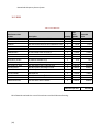
10.2
BOM ............................................................................................................................ 39
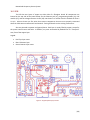
10.3
PCB .............................................................................................................................. 40
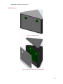
10.4
Enclosure ..................................................................................................................... 42
10.5
Microcontroller Code .................................................................................................. 45
[vi]
Networked Occupancy Sensor System
[vii]
10.5.1
main.c (user code) ................................................................................................... 45
10.5.2
user.h and user.c...................................................................................................... 49
10.5.3
system.h and system.c ............................................................................................. 51
10.5.4
interrupts.c and configuration_bits.c ...................................................................... 51
10.5.5
HardwareProfile.h and TCPIPConfig.h ..................................................................... 54
10.5.6
FPGA Testing Analysis .............................................................................................. 60
10.6
Server Application Code .............................................................................................. 61
10.7
Mobile Website Code.................................................................................................. 64
10.8
Development Environment Setup............................................................................... 70
10.8.1
Microcontroller Programming Environment Setup ................................................. 70
10.8.2
MySQL Database Setup ............................................................................................ 71
10.8.3
Application Server Setup ......................................................................................... 71
Networked Occupancy Sensor System
List of Figures
Figure 1: Network Diagram .............................................................................................................. 2
Figure 2: Sensor Module Top View (left) and Front View (right) ..................................................... 4
Figure 3: A Sample Office, with Sensor Installed ............................................................................. 5
Figure 4: Stock Price Trend of Three Major Building Automation Manufacturers ........................ 10
Figure 5: Existing Sensor Examples ................................................................................................ 10
Figure 6: High-Level Module Hardware Diagram........................................................................... 19
Figure 7: Database Entity-Relationship Chart ................................................................................ 22
Figure 8: Top-Level Software Block Diagram ................................................................................. 26
Figure 9: Top (Component) Layer of PCB ....................................................................................... 40
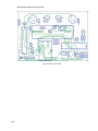
Figure 10: Bottom Layer of PCB ..................................................................................................... 41
Figure 11: Assembled Enclosure .................................................................................................... 42
Figure 12: Enclosure "Exploded" View with Board Model............................................................. 42
Figure 13: Top View of Enclosure with Dummy Board .................................................................. 43
Figure 14: Enclosure Main Body .................................................................................................... 43
Figure 15: Enclosure Front Panel ................................................................................................... 44
Figure 16: Enclosure Top Panel, Showing Mating Side .................................................................. 44
[viii]
Networked Occupancy Sensor System
Acronyms
ABS – Acetyl Butyl Styrene (a common plastic)
ADC – Analog-Digital Converter
AES – Advanced Encryption Standard
BACnet – Building Automation and Control Network
BOM – Bill of Materials
CPLD – Complex Programmable Logic Device
DHCP – Dynamic Host Configuration Protocol
FPGA – Field-Programmable Gate Array
HTML – Hypertext Markup Language
IIS – Internet Information Services
MQP – Major Qualifying Project
PHP – PHP: Hypertext Preprocessor
PIR – Passive Infrared
SPI – Serial Peripheral Interface
SQL – Scripted Query Language
UDP – User Datagram Protocol
WPI – Worcester Polytechnic Institute
[ix]
Networked Occupancy Sensor System
1 Introduction
Within the past three decades, there has been a major shift in the public’s awareness of current
environmental issues and climate change. In 1979, the first World Climate Conference was held to
investigate global climate change (United Nations Framework Convention on Climate Change, 2011).
More specifically, this conference focused on how technology was affecting the global climate. Since
then, other conferences were held, including the popular Kyoto Protocol conference. Among other
findings, these conferences concluded that industrialized nations of the world need to cut back on their
greenhouse gas emissions largely due to the combustion of fossil fuels. One way these nations could cut
back is by simply using energy more efficiently, which is beneficial to all countries, large and small.
Systems found in buildings account for approximately 50% of the total overall energy usage in
developed nations (Salsbury, 2009). Many of these systems are to provide comfort for the people within
even when conditions outside may be unpleasant. However, these systems are not always efficiently
managed and a typical building may continue providing comfort services (lights, heating, air
conditioning) even while vacant. This causes a large amount of energy to be wasted, increasing
operating expenses. Most buildings do not have an intelligent way of controlling systems. The last
person out of a room is responsible to remember to turn off the lights; otherwise the lights may be left
on, wasting energy, for hours or even days at a time. Another case where a large amount of energy is
wasted is when somebody turns their air conditioner up for the workday, but forgets to set it back down
when they leave for the night. By better controlling these systems, a building’s energy consumption may
be greatly reduced.
In addition to the environmental implications of high energy usage, there is also a large cost
associated with the generation and transmission of the energy. This cost is passed on from energy
companies and accounts for approximately 19% of a commercial building’s annual operating expense (E
Source Companies LLC, 2002). The average annual energy usage in a commercial building is about $1.34
per square foot for electricity, and this cost doesn’t include other energy sources such as natural gas or
oil used for heating. It is clearly evident that there is a significant cost motivator for reducing a building’s
energy consumption.
A low-cost system for collecting and analyzing occupancy and usage data might assist building
managers in operating various systems more efficiently. The goal of this MQP is to develop a networked
occupancy sensor system in order to help manage energy usage more effectively. This system is
intended to provide sensory data for control applications in a full- or semi-automatic building
automation system. It will also serve a secondary purpose to provide real-time data about room
occupancy status, lighting status, and current temperature in different rooms, which will be available to
building managers separate from the building automation system. The data, all put together, can aid in
more-responsibly managing the building’s energy usage. Further discussion into the specific project
goals may be found in Section 2: Goals & Specifications.
[1]
Networked Occupancy Sensor System
2 Goals & Specifications
The end-result of this project will be a functional prototype system that will collect data on
occupancy status, lighting status, and temperature in multiple rooms in a building. The system will use
the data to control building systems (e.g. lighting, heating, ventilation) and generate room occupancy,
lighting, and temperature statistics that can later be reviewed by building managers. Ideally, the
prototype system would have been able to integrate with WPI’s existing building automation system;
however, this was not possible due to integration challenges and the existing environment, where
accidental damage was a concern. Beyond performing simple sensory data collection, each module in
the system will be networked together using a standard communication protocol. The information
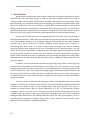
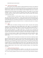
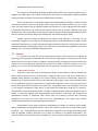
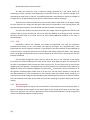
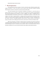
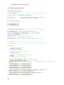
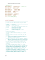
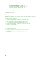
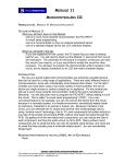
should be available to any authorized internet-enabled device for remote building management. Figure
1 below shows how the devices would be connected in a building automation system.
Figure 1: Network Diagram
In the diagram above, there are three major functions occurring. On the left-hand side, sensor
modules are reporting data back to the building automation server. On the right-hand side, various
building systems are being controlled by the building automation server, while the sensors provide
feedback as to the effectiveness of those systems. The building automation server then provides data to
[2]
Networked Occupancy Sensor System
the web interface server so that it can report back to the user. Note that the building automation server
and web interface servers are not necessarily different machines, as both functions can run concurrently
on one piece of computing hardware.
During the course of the project, a set of design goals were outlined that include the
development of core device functions. The following list describes the goals for these features:
1. Individually-Configurable Devices
Each of the devices should be configurable such that they can identify which room in which they
are located. For the purpose of the prototype system, each device has a hard-coded identifier. Future
work could include the implementation of a software interface to configure the devices dynamically
rather than during production.
2. Multiple Sensors in One Device
The devices should be able to report multiple values. The primary purpose of the devices is to
detect room occupancy, measure temperature and the current light levels, and report this data to the
building automation system. This system is more useful than a simple occupancy detector by providing
additional information that can be used to control the subsystems in the building more efficiently.
3. Reliable Detection
The devices should be able to detect occupancy reliably by any single available method or by
multiple occupancy-detection technologies. In addition, a software algorithm may be used to reduce the
occurrence of false positives from sensor hardware limitations. An individual device should be able to
reliably detect occupancy within a 25-foot radius that covers a 90° or more “pie slice”. The temperature
sensor circuit will be designed to maintain operational accuracy (within ±4°C) over typical interior
temperatures (50°F-120°F). To achieve these specifications, complex sensors may be used (i.e. not a
simple thermistor).
4. Long-term Power Supply
To reduce maintenance costs and simplify operation, the devices should have a consistent
power supply that can last over very long intervals of at least two years. This also implies that the
system should be a low-power device, particularly if it is run on battery power. The intent of this design
goal is to prevent the need for manual replacement of batteries as much as is possible.
5. Data Accessibility
The devices should provide data to a central hub, which may be the building automation system
and/or a separate processing platform. Once collected, the data should be accessible to building
management so that they can track building usage and adjust resources accordingly. This may include
the implementation of a web-based portal through which authorized users can access the data. Ideally,
the information would be accessible on any device, including smart phones.
[3]
Networked Occupancy Sensor System
A consideration is the availability of data to users and to the internal elements of the overall
automation system. For the automation system, it is assumed that there is one central control device
(e.g. a server) and the individual sensor modules would report all data back to that controller. With that
data, the controller could then manage building resources and provide real-time statistics for viewing,
either through a public interface or via a private control terminal.
Another goal of this project is to make it standards compliant and therefore compatible with
existing systems and with new designs. To make the system interoperable with existing building
automation systems, it will be important to make use of the most widely-used (non-proprietary) HVAC
communications standard. The final devices created should be general enough to be integrated into
building automation systems manufactured by multiple vendors.
6. Cost
In a typical installation, each sensor “point” in an HVAC system costs approximately $800 on
average (Spratt, Second Meeting, 2012). This includes the cost of the unit and the cost to install
necessary underlying infrastructure including communications and power connections. For a large
system with multiple buildings, the cost may reach into the millions. To be competitive in the building
automation market, this system must be as economical as possible without compromising functionality.
Ideally, each sensing unit would cost under $100 for the unit itself, not including additional installation
costs.
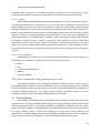
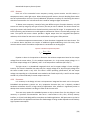
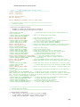
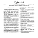
7. Physical Characteristics
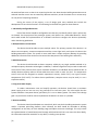
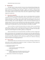
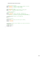
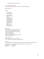
Figure 2: Sensor Module Top View (left) and Front View (right)
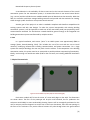
Each sensor module will fit into the corner of a room with edges on the walls. The dimensions
are shown above. The face of the prototype will be plain and functional, but for production the
enclosure would ideally be more aesthetically-pleasing. Sensors will be strategically positioned on the
unit for accuracy and visual appeal. As can be seen in the Front View above, there are two openings in
the front of the enclosure. The passive infrared sensors will poke through where the green-colored
[4]
Networked Occupancy Sensor System
sections are in that image. The prototype’s body will be composed of acetyl butyl styrene (ABS), and will
be printed using a rapid prototyping machine. The unit will weigh less than one pound and will be
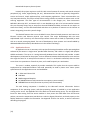
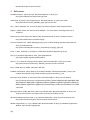
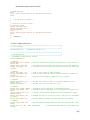
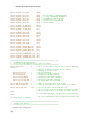
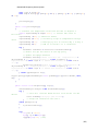
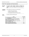
mounted directly to the wall. The units would be corner-mountable and unobtrusive in a typical office:
Networked Occupancy
Sensor Module
2'-6"
2'-6"
11'-0"
Occupancy Detection Zone Limit
8'-8"
8'-8"
Occupancy Detection Zone Limit
8'-3"
2'-6"
Figure 3: A Sample Office, with Sensor Installed
[5]
1'-6"
Networked Occupancy Sensor System
3 Background
There are many factors that must be considered in designing a multi-room system. Before any
development can begin, it is important to know what kind of existing technology can be implemented in
the design, and how it might affect the success or failure of the device. An even more important factor is
how useful the device could become in a real life implementation. The major goal of this project is to
develop a practical device to aid in reducing energy usage.
3.1 Communications Methods
In industry, many proprietary systems exist for building automation systems. Multiple standards
are available for use in communication between modules. It is important in the system design to know
not only what the device needs, but also what modifications would be necessary to building
infrastructure to accommodate the device. Although conforming to an industry standard is a good goal,
this system is primarily meant to be a sensory system and will have generic I/O capabilities regardless of
which method of communication is chosen for the operation of the reporting system that is in use.
3.1.1
Wi-Fi / WPI Wireless
Having access to a building-wide Wi-Fi network could be very beneficial to a multi-room system.
The network infrastructure would already be in place, and no additional hardware or network design
would really be necessary. However, there are some significant disadvantages and considerations to
take into account regarding Wi-Fi. The largest deterrents against using Wi-Fi are existent traffic on the
unlicensed 2.4GHz band and the complex security procedures commonly employed on enterprise
wireless networks.
3.1.1.1 Traffic / Reliability
Largely due to the use of Wi-Fi-enabled computers, phones, and tablets, there are often many
devices attempting to communicate on the same shared radio frequencies at the same time. Although
many businesses have been rolling out IEEE 802.11N wireless access points, many devices still connect
using the IEEE 802.11G or B standard. A major problem with Wireless-G and B is that they operate in the
2.4GHz band along with hundreds of other devices, including Bluetooth devices, microwave ovens,
cordless telephones, ZigBee radios, restaurant coaster calls, and various other systems (Estrin, 2011).
With so many other devices trying to use the network, each one has to “fight” against the others to
communicate. Even if devices using these networks are not actively connected, they still generate traffic
by “pinging” networks to request access. Wireless-N and a new (draft) standard, 802.11ac would allow
for operation on the 5GHz band, thereby avoiding the congestion in the 2.4GHz band (Cox, 2012).
What happens, particularly in high-traffic locations, is that the hardware used for Wireless-G
and B communications becomes saturated with radio traffic and simply cannot effectively communicate
with additional devices, often disrupting devices that are already connected (Estrin, 2011). Cases of this
have been documented during sporting events where unexpected traffic brought down coordinators’
wireless networks. Using an alternative radio band or alternative data transmission system could
potentially alleviate some of the over-usage and increase reliability, but newer Wi-Fi infrastructure is
still not present in most places. The potential traffic and security on enterprise Wi-Fi makes wireless
operation on most existing Wi-Fi infrastructures a poor choice for reliability and long term support.
[6]
Networked Occupancy Sensor System
3.1.1.2 Wireless Security Settings
Many enterprise-scale wireless networks, including the WPI Wireless network, use the Advanced
Encryption Standard (AES) and certificate-based authentication to prevent potential intruders from
gaining access to resources on the network. Rather than using a simple passphrase as is used in other
wireless security systems, there are two certificate files that computers need to use in order to
authenticate with the WPI network. One certificate is used as a server “public key”, and a second
certificate is used as a user-level “private key” (Microsoft Technet, 2003). The encryption level for
certificates at WPI was increased in 2011 from 128-bit encryption to 256-bit encryption, which may pose
a problem for older systems.
Although the public key certificate doesn’t change very often, the private key changes every
year. Connecting the devices via WPI Wi-Fi or a similar network would necessitate downloading the new
certificate(s) to each module every year. This is problematic for devices that are not centrally-managed
by Microsoft group policy, as each device would require a user to manually update the certificates. The
WPI Network Operations department advised that there is no feasible work-around for this limitation
(Sweetser, 2012).
3.1.2
ZigBee
Another option for wirelessly connecting each sensor module is low-power radio operating
separately from the building’s Wi-Fi network (ZigBee Alliance, 2012). ZigBee is a set of specifications
regulated by a group called the ZigBee Alliance for communication using low-power digital radios. It is
optimized for systems that have a low data rate and require a long battery life, but it is also useful in
general low-power applications. In a ZigBee network there is no central unit for transmitting and
receiving data to each device. Each device can transmit and receive data with any other device and can
be used in a mesh network to transmit over long distances. Another advantage is that ZigBee is free to
use for non-commercial purposes. “ZigBee’s main advantages include product interoperability, vendor
independence, thriving and competitive ecosystem and accessibility to broader markets.” (ZigBee
Alliance, 2012)
ZigBee works well for communications over distances of 10 to 100 meters, depending on power
and environmental characteristics, and for low cost and low power consumption situations; this makes
ZigBee an excellent option for building automation, control, and monitoring applications (Kay, 2006).
ZigBee devices can be distanced ten to seventy-five meters apart in most situations and communicate
on unlicensed bands of 2.4GHz. ZigBee boasts low power consumption; conserving power by having the
individual nodes in the network spending most of their time in sleep mode. They connect to the
network, communicate with other nodes, and then go to sleep. Because of the low duty cycle of the
nodes, the ZigBee network is able to lower its power consumption making it a very energy efficient
technology.
3.1.3
Building Automation Standards
There are many building automation standards in use today. There are two main open
standards, known as BACnet and LonWorks, but there are very many proprietary systems that are still in
use in various existing installations and some that are used by even the large automation companies
[7]
Networked Occupancy Sensor System
(Snoonian, 2003). In general, most building automation companies are now using BACnet as their
communications platform of choice, even if they still have non-standard, legacy systems in place.
3.1.3.1 BACnet
BACnet (short for Building Automation and Control NETwork) is “a data communication protocol
for building automation and control networks” and its intent was to standardize communications
between different elements in an HVAC system (Newman, 1998). One major feature was that it would
also allow expandability for other systems that had similar I/O characteristics. Part of this is the ability of
BACnet to inter-operate with other systems, including legacy systems (Delta Controls, 2007). BACnet
specifies a protocol for controlling building automation elements at every level, from workstations to
networking hardware to individual devices. In addition, BACnet incorporates multiple media for data
transmission, including Ethernet; ARCNET; master/slave token passing (a BACnet twisted pair
specification); point-to-point (another BACnet specification); LonTalk; and BACnet/IP. This makes
BACnet one of the most widely-usable systems. Where older systems exist, a “BACnet gateway” may be
used to translate to and from the legacy signals so that replacement of equipment isn’t immediately
necessary.
3.1.3.2 Other Standards
Although BACnet is most popular, there are some other standards in use by various companies.
The number of old “standards” is large, but some of the more common ones are:
CEBus
EIB
Local Control Network (LCN)
Modbus
LonWorks (LonTalk)
(Schor, Sommer, & Wattenhofer, 2009), (Siemens Industry, Inc., 2012)
Among those listed above, the most popular alternative to BACnet is LonTalk, which is another
open standard more common in Europe (described in more detail below). Modbus is the standard
formerly created and used by Schneider Electric, one of the largest building automation companies in
the world (Modbus Organization, Inc.). Most of these building automation systems have been
discontinued in favor of the open standards offered by BACnet and LonTalk.
3.2 Smart Buildings
Smart buildings are buildings that use integrated sensory systems in order to control heating,
ventilation, and air conditioning (HVAC), lighting, and/or other devices/systems that do not always need
to be running (Sinopoli, 2010, p. 3). The level of a building’s “intelligence” is dependent not only on what
sensory and control hardware is installed, but also on the algorithms and control software that manages
the system (Salsbury, 2009, p. 1081). Smart buildings can range from massive buildings with
sophisticated, centrally-managed systems (e.g. the Pentagon) to simpler buildings with many individual
sensors that don’t necessarily link together, such as a personal residence (Snoonian, 2003).
[8]
Networked Occupancy Sensor System
3.2.1
Systems with Central Control
There are many systems for controlling various HVAC and lighting systems. A major problem in
large systems is that there are many proprietary systems that cannot be easily used with each other
(Snoonian, 2003). BACnet’s major competitor, LonWorks, is meant “to facilitate the need to integrate
multiple system components using a common system architecture and infrastructure” (LonMark
International, 2012). Both structures have the same goal, and either technology would be suitable for
use in designing new sensors that would be used for building control. Both of these control systems are
proven and effective, even in very large installations such as the Le Coeur Défense building in Paris,
which uses 17,000 individual LonWorks devices (Snoonian, 2003).
3.2.2
Systems with Non-Networked Control
Other systems are much simpler. The most basic version of non-networked control is the light
controller one might see in a public restroom. Many restaurants, offices, schools, and other locations
have lights that turn on as you walk in, and turn off after a certain amount of time. Typically these are
sensors that are only connected to the light switching circuit, but are otherwise not connected.
A similar system can be seen walking through the corridors of East Hall. As one walks down the
hall, lights switch on automatically. A short time afterwards, the lights turn back off. Similarly, in many
classrooms the lights will turn on as somebody enters, then turn off after a period of time. This system is
suitable for most purposes, though it may be inefficient if a person is only in the room for a short time.
This type of smart building is still significantly more energy efficient than buildings with no automation,
but without a central “brain” in the system, the building provides less control to building management
personnel.
3.2.3
Demand for Smart Buildings
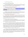
The demand for smart buildings has increased over the last decade. This can be clearly seen in
the Worcester area, where there have been multiple building projects that incorporate smart building
principles. Recently, institutions of higher education and corporate partners have begun working
together collaboratively towards energy saving programs (SynergE Worcester, 2012).
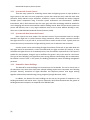
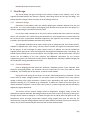
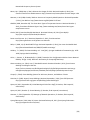
In addition, the demand for smart buildings can be seen by the growth of companies in the
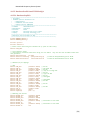
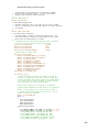
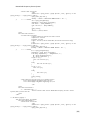
building automation and control sector. Figure 4 (Microsoft, 2012) below demonstrates the growth of
building automation companies as compared to the S&P500 index:
[9]
Networked Occupancy Sensor System
Figure 4: Stock Price Trend of Three Major Building Automation Manufacturers
As Figure 4 demonstrates above, building automation and control manufacturers including
Schneider Electric, Honeywell, and Siemens have been consistently outperforming companies in other
sectors as measured by their stock prices. As can be seen in the graph, many companies were hard-hit
by the recession in early 2008, yet building automation companies were able to recover faster than
other industries. It is reasonable to conjecture that there is a mature market for this type of device that
is growing even more as people are more conscious of energy costs and environmental impacts.
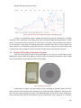
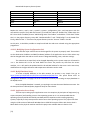
3.3 Existing WPI Building Automation Systems
There are many different systems and technologies in use even just at WPI (Spratt, Initial
Meeting with Facilities Staff, 2012). BACnet is primarily used in the building’s automation system. At WPI
there are two BACnet systems that cover 85% of the buildings.
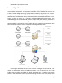
Figure 5: Existing Sensor Examples
Pictured above in Figure 5 are two existing sensors in buildings on the WPI campus. As can be
seen on the left, some elements were provided by the Automated Logic Corporation. Sensors like the
box at left are simple temperature sensors. One additional feature is that some of these temperature
sensors include simple switches that people can press to indicate the room is occupied, or to override
[10]
Networked Occupancy Sensor System
the normal set temperature for intervals up to a time limit set by building management (Spratt, Initial
Meeting with Facilities Staff, 2012). The sensor on the right is a passive infrared (PIR) sensor that checks
for people moving in the room. These sensors are the type that is often used to turn the lights on or off.
Despite having many sensors, many zones are not finely controlled. The WPI Campus Center, for
example, runs based on a timer. At 6:00 AM, the system sets its zones to “occupied” and then cools or
heats the rooms to their specified set points. Then at midnight, the system sets the zones to
“unoccupied” and virtually ceases managing the temperature and ventilation, only turning on to prevent
damage to the building (i.e. not too hot to damage equipment, not too cold to freeze pipes). The system
at present will also allow for major inefficiencies such as running air conditioning equipment in addition
to running the heating boilers.
Newer buildings including East Hall and the Recreation Center as well as many updated rooms
have been equipped with at least basic occupancy sensors to manage the light controls.
3.4 Power
Each unit in the system will need to be individually powered. When choosing the method of
powering these devices, it is important to take into consideration; the availability of the power source
where each unit will be located, the ease of installation, and any safety concerns regarding the power
source. The three main power sources that were investigated were batteries, mains voltage, and power
over Ethernet. Photovoltaics, while a popular method of powering low-power devices, would not be a
realistic option for this application because fluorescent lights are used in each room where the units
would be located. Photovoltaics work best in direct sunlight or other locations with high energy
radiation (e.g. ultraviolet rays) but do not work well with fluorescent lighting, which is much lowerenergy radiation.
3.4.1
Batteries
Using batteries to power each unit in the system would make the design and construction of the
system very easy. Batteries are also generally safe to people who come into contact with them. They can
explode but that only occurs when they have been used improperly. Also, batteries can spontaneously
leak dangerous chemicals; this is a fairly rare occurrence. While batteries are mostly safe when in use,
batteries are very harmful to the environment when not properly disposed of. Some batteries produce
toxic metal pollution by letting dangerous elements like lead, mercury, and cadmium into the
environment.
However, the main disadvantage of using batteries to power the system is that that the
batteries would need to be regularly replaced. Someone would have to go around to each room with a
unit installed and replace the batteries. Constantly replacing batteries can be time consuming and very
expensive. But if the batteries are capable of lasting for a couple years at a time without needing to be
changed, then using batteries as the unit’s power source may be possible.
The networked occupancy sensor system will consist of units that would ideally require very
little power. Since a significant part of this project’s purpose is to reduce the energy usage of a building
the system should be designed to use energy efficiently and to conserve power. Given their advantages
[11]
Networked Occupancy Sensor System
batteries are a potential option for powering the system, but may not be a sustainable choice due to
manufacturing and disposal concerns.
3.4.2
Mains (AC) Voltage
Powering each device from the mains is feasible because generally wall outlets will be available
for use. Since outlets already exist is each room, installation would be simple. In most cases it would not
be necessary to do any additional wiring in the building to power each unit, provided that the sensor
was located near an available outlet. Mains voltage in the United States is standardized to 120V. This
provides a much higher voltage than is necessary to power each device. While, to most professionals,
120V is considered low-voltage and not dangerous, significant electrical injury can still occur (Morse,
2006).
Since the mains voltage is much higher than what would be needed for each device, dedicated
power lines could be installed to provide a lower voltage. Dedicated power lines are special low-voltage
wiring that connects to the mains voltage. When installed, it provides readily available low-voltage
power sources. However, these dedicated power lines would need to be installed in every room where
there is a unit. This makes installation more difficult but these power lines have a much lower voltage
than the mains voltage, making dedicated power lines somewhat safer than directly using mains voltage.
3.4.3
Power over Ethernet
Power over Ethernet (PoE) is a viable method for powering a device as well as sending and
receiving data through a single cable. Unlike its competition, the Universal Serial Bus (USB) which is
limited to a maximum cable length of five meters and can support less than 2.5 W of power, PoE can
provide up to 12 W of power with a cable of 100 meters. PoE has major advantages over other
technologies that include:
•
•
•
•
•
•
Easier deployment – Access to hard-to-reach locations or places with a lack of space for
power deployment, such as roadside, external walls and internal ceilings, becomes
much simpler and easier to maintain.
Lower cost – Costs can quickly escalate when the installation of separate power outlets
are factored into a project, PoE switches save both time and money by avoiding the
need for separate installation of Power outlets.
Multi-location – Wherever there is an Ethernet connection, a powered device can be
used.
Increased uptime – If a UPS is used in the power supply for the PoE switch, reliability
rises towards the optimum “five nines” due to reliance not being placed on the mains
AC voltage supply.
Improved safety – 48 Volt Direct Current levels are much safer than AC mains voltage.
Plug and play – Equipping applications with PoE switches is simple and enables
interoperability with a growing variety of devices. (Power over Ethernet)
[12]
Networked Occupancy Sensor System
This method is standardized according to IEEE 802.3at-2009. The standard requires using a
category 5 or higher cable. CAT 5 cables consist of four twisted pairs and the power would be supplied
using two of them; leaving the remaining two differential pairs for data.
Power over Ethernet is a convenient method for powering devices because it utilizes existing
infrastructure without relying on AC power outlets, which are not always available for use in every
room. The most common way to implement power over Ethernet is to use a mid-span hub. Each device
is tethered with a cable to the mid-span hub and the hub sits next to a switch. Mid-span hubs were
developed as a way to power devices over Ethernet without having to replace existing network switches
with new switches specifically designed to enable power over Ethernet (Dagan, 2005).
Another attractive feature of powering the devices using Ethernet is that data can be
transmitted through the same cable that is powering the device. This would allow for a simpler system
and easier installation than a system that required multiple cables per device or an alternative and more
complicated method of powering the device. Also, Ethernet can communicate using BACnet, one system
that WPI uses to communicate between building devices.
3.5 Sensors
It is necessary for each unit of the networked occupancy sensor system to be capable of
detecting, measuring, and providing data on the temperature, light status, and occupancy of the room
being monitored. The types of sensors included in the design will be; temperature sensors to be used to
monitor the room temperature, light detection sensors to be used to determine whether or not the
lights are on in a room, and motion detecting sensors to monitor the occupancy status of the room.
3.5.1
Temperature Sensors
There are seven basic types of temperature sensors; thermocouples, resistive temperature
devices (RTDs), infrared sensors, thermometers, change-of-state sensors, and silicon diode sensors
(OMEGA, 2000). However the design of this system requires the sensor to electronically output the
temperature, therefore, bimetallic devices, thermometers, and change-of-state sensors would not work
for this application. Using infrared sensors to measure the temperature of the room may have issues
with accuracy when there are people in the room. Also, silicon diode sensors were designed to be used
in the cryogenic temperature range which is well below the temperature range that is necessary.
Thermocouples measure temperature with a change in voltage and RTDs measure temperature with a
change in resistance. Voltage, with thermocouples, and resistance, with RTDs, will change when
temperature increases or decreases. Both sensor types can positively increase with increasing
temperature, but RTDs are much more linear than thermocouples. This could make resistive
temperature devices easier to work with than thermocouples.
A temperature sensor using a thermistor would be easy to design. Its resistance varies notably
with its temperature and could be placed in series with another resistor with a known and constant
resistance. Thus, voltage between the two resistances (compared to the voltage applied over both)
could be digitized, allowing calculations to be done to determine the applied temperature. The
resistivity of the thermistor varies with its temperature. It may increase or decrease (a feature specified
[13]
Networked Occupancy Sensor System
by the manufacturer). Thermistors are partially characterized by their error, which is given in %/°C. They
can require calibration (which complicates design) but they are cheap.
While designing a custom temperature sensing module would be relatively simple, purchasing a
pre-constructed temperature sensor component is often a better option. By purchasing an existing
temperature sensing component the overall system design is simplified and reduces potential for
calibration error.
3.5.2
Light Detection Sensors
Each unit in the system needs to be able to detect whether or not the light in the room is on.
Photodetectors can be used to determine the light status in the room. Three types of photodetectors
that are frequently used for similar applications are; photoresistors, photodiodes, and light-emitting
diodes (LEDs) (Andromeda, 2013).
Photoresistors measure light with changes in resistance. As the light intensity increases, the
photoresistor’s resistance decreases. This type of photodetector has an analog output. Preferably a
photodetector whose output is digital would be used in order to reduce the complexity of the design.
Photodiodes can be used in photodetector applications. The output of a photodiode can either
be analog or digital depending on how it is designed to be used. To be used for measuring the amount of
light present, an analog output can be generated. Or it can be designed to generate a digital output that
can be used for control or switching applications. Digital output would be ideal for this light detection
application because it will simply output whether or not the light is on in the room.
It is also possible to use an LED as light sensor. This is an attractive option for a light detection
sensor because it can reduce the cost of the system by using a single component for multiple functions.
The LED can switch between emitting light and detecting it. To detect light it works like a photodiode
but it is only sensitive to light with wavelengths that are equal in length or shorter than the wavelength
of the light that the LED emits.
3.5.3
Motion Detecting Sensors
There are many different types of motion detecting sensors currently on the market. Some are
active sensors; they send out energy usually in the form of either light, microwaves or sound and then
wait for that energy to come back. When the returning signal has been received, calculations are made
to determine whether or not something has moved in front of it. Then there are passive sensors that do
not send out any energy, for example the passive infrared sensor that simply detects ambient energy
levels.
3.5.3.1 Passive Infrared
Passive infrared sensors work by detecting changes in levels of infrared radiation. A PIR sensor
module will detect a human by noticing the difference radiation that it emits compared to the room
because everything emits some radiation, with warmer things emitting more than cooler things. “The
sensor in a motion detector is actually split in two halves. The reason for that is that we are looking to
detect motion (change) not average IR levels. The two halves are wired up so that they cancel each
[14]
Networked Occupancy Sensor System
other out. If one half sees more or less IR radiation than the other, the output will swing high or low.”
(PIR Motion Sensors, 2012)
This type of motion detecting sensor is very common and widely used because it is small,
inexpensive, low-power, and easy to use. Using passive infrared sensors in the room occupancy
detection system is one of the better options because of its ease of implementation and accuracy. The
low-power consumption is an attractive feature because the purpose of this design is to ultimately assist
the user in lowering unnecessary energy usage in their building so it is necessary to design a system that
will save more energy than it consumes.
3.5.3.2 Ultrasonic
Ultrasonic sensors detect motion by generating high frequency sound waves and detecting the
change in time it takes to send and receive the signal. This type of sensor is used to detect the presence
of something and to measure how far away it is. By using sound rather than light, this sensor can be
used in certain applications that are impossible for other sensors; detecting objects that are translucent.
One disadvantage in using ultrasonic sensors to detect objects is that “there’s no way to tell the
difference between small objects and large objects because the pulse that’s emitted is cone shaped.
Because of the shape, an echo will be returned by all objects the pulse comes into contact with.”
(Garcia).
For this application, ultrasonic sensors may not be a practical option. A major problem is that if
something is added to the room (not a person) after the sensor has been calibrated, the ultrasonic
sensor will continuously report false positives since it cannot differentiate between an inanimate object
and a person. However, if coupled with another type of sensor, it could potentially greatly improve the
accuracy of the system as a whole.
3.5.3.3 Microwave
Microwave sensors send out microwave radio energy and wait for it to come back. When a
person walks in front of this sensor, the sensor detects the change in the returning energy. This type of
sensor is often used in automatic door openers.
There are two main microwave sensor designs; monostatic or bistatic. In monostatic systems,
the emitter and receiver are together in one unit but in bistatic systems they are in separate units. The
main differences between the two designs is that with a monostatic unit the detection range is smaller,
but users can define the area of detection more accurately than with bistatic units. Also, bistatic are
more likely to report false positives.
While microwaves are capable of passing through many material types, it cannot penetrate
metal objects (Microwave Motion Detector Guide). Most obstacles that would inhibit other sensors are
not a problem for microwave sensors. Being able to detect motion behind various objects is a very
attractive characteristic of this type of sensor. However, this is limited to objects that are not metal.
Large metal objects (e.g. desks, tables) in a room would create areas in the room where motion
detection would not be possible.
[15]
Networked Occupancy Sensor System
3.5.3.4 Acoustic
Acoustic sensors detect occupancy by listening for sounds from people in the room. This type of
sensor is prone to false positives because of environmental noise. While alone the acoustic sensor is not
very reliable, it can enhance the capabilities of other sensors when the sensors are combined in one
unit. Acoustic sensors are inexpensive and can easily be integrated with other sensors to reduce the
occurrence of false positives.
3.6 Data Access
The data that is collected from each unit should be available for building managers to view so
that they can track building usage and adjust resources accordingly. Also, the data gathered from the
units can be used to provide real-time statistics to be viewed. It is necessary to make this data easily
accessible from anywhere. This could be done by developing a mobile platform or a mobile website
interface.
3.6.1
Mobile Platform Development
There are only a few major players in the smartphone market. A recent press release from
comScore (a network market analysis group) shows that the Android operating system has achieved a
52.2% market share in the United States (comScore, 2012). Following Android, the next big systems in
use are Apple iOS at 33.4% and RIM Blackberry at 9.5%. This data doesn’t factor in the increasingly
popular tablet format for computing, so there are definitely more Android and iOS devices on the
market that are unaccounted for in these percentages. Conveniently, most applications (apps) written
for mobile phones will run properly on tablets in the same operating system family (i.e. iPhone apps will
work on iPads, Android apps will run on Android tablets).
Android and Blackberry apps are both written in Java (Kowalski, 2010). This being the case, it
should be possible to more easily re-use common code for creating a Blackberry app from the Android
app’s codebase. However, iOS apps are written in C# (“C-Sharp”), a derivative of the C programming
language.
3.6.2
Mobile Website Interface
In general, creating a website is very easy and there are a plethora of internet resources and
information to assist in the design and creation of a website. Creating a website is a viable option to
present room occupancy data to users of the system. Websites can be accessed on virtually any
computer or mobile device (including smartphones) with access to the internet. Generally, websites are
not designed with smart phones in mind. In a situation where a mobile-friendly site isn’t created, a
website may be very difficult to navigate. However, it is possible to design a website that can be
specifically optimized for mobile device use by simply making minor adjustments in the design and
adding a couple tags in the <head> section of the webpage. “Mobile META tags can be used in XHTMLMP and HTML markup to tag the document as optimized for mobile devices … A lightweight and
responsive full-HTML mobile web experience provides the best user experience across a mobile network
and on the smartphone browser.” (Rahn, 2009)
[16]
Networked Occupancy Sensor System
Implementing a mobile website interface may be the best option for presenting the data on
room occupancy rather than immediately making a smartphone app. A webpage can be accessed not
only from any computer but also on any type of mobile device; it does not matter whether the device is
an Apple or Android product. This is unlike a smartphone app where it would need to be designed for
either iOS or Android. Therefore, at least two apps would need to be designed in order to make the data
on room occupancy readily available to most people.
[17]
Networked Occupancy Sensor System
4 Methodology
As stated above, this system is primarily meant to be used in collecting room occupancy data.
The usage data would be used to manage light controllers and other system controls in order to reduce
energy consumption of buildings. The data will also be made available to authorized individuals. The
intermediate stages required to develop a robust product include:
1. Researching and analyzing various room occupancy sensing systems and networking
technologies
2. Identifying the best combination of technologies
3. Identifying hardware and processing needs for chosen technologies
4. Designing and constructing a prototype system
5. Evaluating accuracy and scalability of the system
6. Determining areas for improvement (see Conclusions)
4.1 Research and Analysis
Background research, found primarily in the previous section (Section 3: Background), comes
from academic journals as well as publications such as press releases from industry and the government.
In addition, to provide a clear assessment of currently-available systems and technologies, distributor
and manufacturer websites and/or catalogs and other marketing literature were used in preparing the
background research section. The demand/market for the new devices was found by interviewing WPI
employees who work with relevant building systems and by observing the general market trend in the
building automation and control industry.
Background research was conducted in various major aspects of the system design. This
included research into networking, power supply options, existing systems with similar functionality,
types of sensors, and interface designs that would be available for use in this project. The results of the
research were used to analyze systems that are available on the market to determine the best approach
for the design of this MQP.
4.2 System Design
After researching available occupancy-detection hardware, networking hardware, and power
supply hardware, the availability and ease of integration for each option was compared against the
alternatives. First the network and communication option was chosen, which led to the selection of the
power supply. The general type of controller/processing unit to use was chosen based on personal
experience with different devices. With clear expectations on which inputs and outputs would be
necessary, specific sensors were chosen to be integrated into the system. Finally, a processor was
selected that could handle the necessary control operations.
[18]
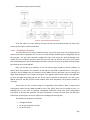
Networked Occupancy Sensor System
Figure 6: High-Level Module Hardware Diagram
4.2.1
Power and Communications
The networking option chosen for this project is Ethernet over twisted pair copper cable. This
led logically into using Power over Ethernet as the system power supply, as it reduces overall
complexity. After the options were weighed, it was decided that using a wireless system in the 2.4GHz
range would be a poor plan for the reasons described in sections 3.1.1 and 3.1.2 (Wi-Fi and ZigBee,
respectively). In addition, the convenience of Power over Ethernet made Ethernet as a data service a
highly-attractive design choice. This design is also simpler to integrate into the BACnet system, as
Ethernet is one of the primary infrastructure options in BACnet and is widely available in many buildings.
As described in the background section, BACnet specifies how the individual devices communicate to
and from the building automation server.
In the system, each module will need to be powered individually and communicate to the system.
Utilizing Power over Ethernet (PoE), the system can be powered using the same cable over which data is
transmitted within the system. This simplifies the installation of the system since it relies primarily on
preexisting infrastructure.
Originally, the power supply was designed to use Power over Ethernet to produce a stable, lowvoltage power supply for the rest of the circuit. However, the complexity of 802.3af made creating a
new PoE power supply too difficult. To solve this problem, an off-the-shelf IEEE802.3af compliant PoE
module was added to the design to provide the necessary regulated 3.3V output. This module performs
all of the PoE interfacing with minimal additional configuration.
[19]
Networked Occupancy Sensor System
4.2.2
Sensors
Each unit of the networked room occupancy sensing system contains two PIR sensors, a
temperature sensor, and a light sensor. When choosing specific sensors, the main deciding factors were
ease of implementation and cost. The only additional component necessary for interfacing the sensors
with the microcontroller is a 3.0V reference that is used for analog-to-digital conversions.
To detect room occupancy, instead of using two different types of motion detectors, only PIR
sensors are used. By using only one type of sensor, the cost per unit is reduced. The sensors chosen are
long-range sensors and therefore have limited sensitivity across the full range. To compensate for this
loss of sensitivity, two PIR sensors are used together to determine if there is a warm body moving in the
room. The specific PIR sensor chosen provides a digital output that has integrated false-positive
reduction, which allows for two sensors to be used without causing more false-positives.
For ambient temperature measurement, a linear thermistor integrated circuit was chosen. This
is a low-cost device that does not require an additional signal-conditioning circuit like many other
resistive sensors would. The ambient temperature is converted to an analog signal.
Equation 1: Ambient Temperature Equation
𝑇𝐴 =
𝑉𝑜𝑢𝑡 − 𝑉0°𝐶
𝑇𝐶
Equation 1 above is the equation to determine the ambient temperature based on the output
voltage from the sensor where; TA is the ambient temperature, Vout is the sensor output voltage, V0°C is
the sensor output voltage at 0°C (400mV), and TC is the temperature coefficient (19.5mV/°C).
The light sensor is a photodiode integrated circuit and its output voltage is linear with light
intensity. The sensor’s datasheet lists values only for a supply voltage of 5V, but the supply voltage from
the sensor module circuit is only 3.3V. This value is within operating specifications, but the output
voltage corresponding to an illuminated room needed to be found empirically. A well-lit sensor output
around 2.5V, and a moderately-lit sensor output around 1V.
4.2.3
Processor
It is necessary in the design to have a microprocessor integrated into each unit in the system.
Embedded microprocessor systems are very inexpensive because they use a relatively standard
hardware architecture that fits a large variety of applications. Also, software is significantly easier to
develop than custom hardware is to design in order to do the same task.
There are many options for embedded systems-on-chip to choose from. For this design it is not
necessary to purchase microcontrollers that have a state-of-the-art CPU, GPU, off-chip memory
interface, or 2-level cache designed for smartphone and tablet applications. DSP processors may also be
over-powered for this application and have the disadvantage of being vendor dependent and relatively
high in power consumption.
[20]
Networked Occupancy Sensor System
Instead, this project requires a small CPU with a small amount of memory and control-oriented
peripherals (e.g. timers, digital/analog I/O, etc.). Microcontrollers like this are generally designed for
sensors and control, simple appliances/toys, and low-power applications. These microcontrollers are
very low-power devices; this project needs to be as energy efficient as possible to reduce strain on PoE
sourcing equipment. The main types of microcontrollers in this category are; Texas Instruments
MSP430’s, Microchip PIC’s, and Atmel AVR’s. It was decided to go with a PIC microcontroller because
they are extremely cheap, easy to setup (have internal EEPROM and RAM, and most do not require an
external oscillator), and are well-documented and there are a plethora of resources on the internet to
assist in integrating it into this system’s design.
Two desired features that are not included in many feature-limited processors are Power over
Ethernet circuitry and Ethernet physical layer control. One major disadvantage with the more
sophisticated chips is that they are almost always surface mount and are hard (or impossible) to work
with on a normal prototyping board. For ease of development, these systems are instead handled by
dedicated additional hardware, described more in the section Final Design.
4.2.4
Application Server
An application server is necessary to this project for hosting the website and for processing data
collected by the sensors. A single server provides both functions, and is built on a legacy Dell Optiplex
GX260 workstation. The server is running Microsoft Windows Server 2003 R2 and provides a stable
development environment for the project. A minor difference between the development server and one
that might be found in an enterprise environment is that it is not domain controlled, does not have
server-class virus protection or firewalls in place, and is used frequently as a workstation.
The server is modest, especially by modern standards. This implies that the system could be
implemented on antiquated hardware and could potentially be used by home users. Some system
specifications for the application server are listed below:
1.7GHz Intel Celeron CPU
1GB RAM
64MB Integrated Graphics
10/100MB Ethernet Card (connection to occupancy system network)
1000MB Ethernet Card (connection to primary local area network)
The web hosting component is handled by the Microsoft Internet Information Services
component of the operating system, and data processing element is handled by a Java application
running on the server. See Appendix 10.8.3 for details on the web hosting set-up. The Java application
listens for data coming from the sensor modules. It then parses the useful data from the Ethernet
packets, converts the temperature raw data into a value in degrees Fahrenheit, and sends a query to the
MySQL database to update the information. See Appendix 10.6 for the source, as well as comments
describing the program.
[21]
Networked Occupancy Sensor System
4.2.5
MySQL Database
The interface development relies on the operation of a database server and an application
server. The interface itself runs on the application server, and it retrieves data from the database server.
The microcontroller transmits data from the sensors to the database (via the application server),
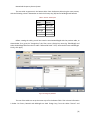
updating the data tables. Figure 7 is the database’s entity-relationship chart. It outlines the information
contained in each table within the database and the relationship between those tables.
Figure 7: Database Entity-Relationship Chart
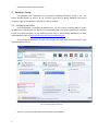
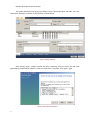
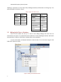
The database is hosted on the WPI Computing and Communications Center (CCC) MySQL server,
which is hosted across multiple physical servers. User interface with the MySQL server is done through
Oracle MySQL Workbench, any changes made on one physical server are propagated across the others
(Oracle, 2013). MySQL Workbench is a graphical tool that can be used to create tables in the database
and edit data within the database tables. The database server is typical for enterprise environments,
running the enterprise version of MySQL database server.
The database is updated with information from the microcontroller as it is received by the
application server. The application server hosts an application that analyzes data coming from the
microcontroller and separates out the useful data. The data are then uploaded to the MySQL server
where they are simply added to the existing data tables.
4.2.6
Mobile Website
From the MySQL database, the data from the sensors is displayed on a website designed for
mobile devices. The layout and navigation of the mobile website is specifically designed for use on
smartphones. Mobile websites need to accommodate the low-resolution, typically vertical, screens of
mobile devices. The mobile website for this project is designed with all of the content formatted in a
single-column interface. Along with constraining all scrolling to the vertical axis, text size and all clickable
areas are auto-scaled to be large enough to be easily read and to be accurately “clicked”.
To retrieve data from the MySQL database, the website uses PHP (see Appendix 10.7 for the
mobile website’s code). PHP stands for PHP: Hypertext Preprocessor (The PHP Group, 2013). PHP is an
open-source scripting language and PHP files may contain text, HTML, and JavaScript code along with
the PHP code. The server executes the PHP code and returns the result to the browser as plain HTML
(along with JavaScript, if used). PHP can easily be used to output data from a database to web pages.
[22]
Networked Occupancy Sensor System
4.2.7
Electronics Assembly & Enclosure
Most electronic components will be mounted directly to a custom printed circuit board. The
circuit board will be designed and then manufactured off-site. Before making the circuit board, each
electronic subsystem will be tested in a laboratory environment. A risk involved in using a custom PCB is
that if anything is overlooked, it can cause problems later on that are much harder to fix.
The enclosure protects the electronics from environmental hazards (e.g. dust, curious people)
and allows for easier installation in a room. The enclosure will be designed to fit the electronics
assemblies. Some considerations in designing the enclosure are ease of access to the circuit board, size
constraints, and manufacturability.
4.3 Evaluation of Complete Prototype System
Electrical testing was performed on individual portions of the design. Each sensor module was
tested on breadboards, and the sensors’ output was read on a laboratory digital multimeter. After
electrical testing, the sensors were tested with the microcontroller to observe proper communication
between the sensors and the microcontroller. After the electronics assemblies were completed,
additional testing was done to verify that the PCB and the rest of the circuit were working.
With the completed modules, the whole system was tested to verify that it can sense occupancy
in a room in accordance with the design guidelines set forth in Goals & Specifications. In addition to
verifying that humans work to set off the sensors within the expected range, attempts were made to
generate false positives by “tricking” the sensors (e.g. using a hair dryer to blow hot air past an IR
sensor). The modules were also set up to provide visual feedback to demonstrate that the temperature
and light sensing subsystems were operational.
In the event that networking did not work properly, hardware and software debugging
techniques could be used to prove that the sensing system operates correctly. With an operational
networking system, data were collected and checked for errors while the system was running in a
“steady state”.
The web interface is largely dependent on data from the sensors. Prior to getting real data from
sensors, dummy data was used to test the web interface. The web interface was tested by viewing it on
multiple mobile devices and on computers, and it was shown that the data is being generated
dynamically from the database.
[23]
Networked Occupancy Sensor System
5 Final Design
The overall design has gone through much iteration. Despite many setbacks, many of the
originally-intended features now function. However, some things had to be cut from the design. This
section details the design process and many of the final design decisions.
5.1.1
Schematic Design
ExpressSCH, a free software tool, was used for designing the schematic because of its cost and
ease of use. It is a very useful program for designing small printed circuit boards. Since this project is a
relatively simple design, ExpressSCH worked very well.
For all of the major components in the circuit, custom symbols had to be created to represent
them in the schematic. This involved using the datasheets for each component to recreate them with
the correct pin-outs in ExpressSCH. Standard components, like capacitors and resistors, were already
included in the ExpressSCH database and were easily inserted.
The schematic underwent three major revisions prior to making the PCB, and a fourth revision,
available in Appendix 10.1, after testing. The first revision includes the original microcontroller chosen
for the project, as well as designs for power supply circuitry. In addition, this version included the
originally-chosen light sensor, which was replaced by a through-hole component later in the design. The
second revision includes the new microcontroller, the new light sensor, and the PoE module. The third
revision has the addition of the 3.0V reference and additional connections for the in-circuit
programming system. The final fourth revision, found in Appendix 10.1: Schematic includes changes that
were made after testing the modules on the PCB.
5.1.2
Circuit Verification
Prior to designing the PCB around the schematic, individual portions of the schematic were
tested on prototyping boards. The elements that were tested were the ones that could be tested
individually. This includes each of the sensors, as well as the PoE module.
During the initial testing of the sensors, all sensors functioned generally as expected. The PIR
sensors had an output voltage between 3.2-3.3V when motion was detected. They were sensitive
enough to detect most slight movements. However, when approaching the sensor directly from a
distance exceeding 25’ it is possible to go undetected. To reduce the impact of this blind spot, the
module should be installed in a corner of the room at least 5’ up from the ground, with the PIR sensors
angled very slightly downwards.
The thermal sensor’s output voltage varied as temperature changed, closely to how the
characteristic equation describes. No testing was done at this point to verify the accuracy of the sensor.
The light sensor outputs a voltage of ∼2.5V when the lights are on and 0V when the lights are off. The
temperature sensor and light sensor both produce analog outputs that must be read into the
microcontroller using the analog-to-digital converter (ADC) module. Once data from the two sensors are
read in, they must be translated by the microcontroller to make the data useful.
[24]
Networked Occupancy Sensor System
The ADC was tested by using a reference voltage generated by a lab power supply. By
calculating the ADC resolution and comparing the expected value for the reference voltage, then
outputting the actual value on I/O pins, it was determined that is was possible to read in the voltages to
a margin of error of approximately 0.04V, which is sufficiently accurate for the design.
The Power over Ethernet module was tested to verify that it could obtain a 3.3V supply voltage
from the Ethernet line. Initially,the data ports used were not connected to a PoE sourcing device, but
after borrowing a PoE injector, the PoE module was able to output a useful voltage.
Two parts that should have been tested were the voltage reference regulator and the Ethernet
oscillator. Both of these parts did not arrive until after the deadline for ordering the PCB, and were
therefore untested until on the PCB. These two parts caused additional problems on the PCB, as
described below.
5.1.3
PCB
ExpressPCB, another free software tool related to ExpressSCH, was used for component
placement and routing on the circuit board (see Figure 9 and Figure 10 in Appendix 10.3). Since
ExpressSCH was used to create the schematic, it was possible to link that schematic to the PCB design to
verify the net list. Linking the schematic to the PCB file made routing significantly easier; when drawing
traces, the program showed which pins to connect based off of the net list for the schematic that was
linked to the PCB file.
The PCB went through four major revisions. Due to the errors in the schematic, a few routing
errors were not discovered during the review process. Wires were added to switch the connections to
the LEDs on the MagJack and to connect the center tap pin to VDD. The only other error on the PCB was
related to the 3.0V regulator. The regulator was not set up properly in the schematic, and it required an
additional resistor to be soldered in between its input and VDD. Conveniently, the no-connection pin of
the regulator provided another solder point to fix the error. One last minor problem on the PCB was
non-ideal placement of a few components on the secondary side of the board; which caused pins to
inconveniently extend through the board hindering the positioning of the Power over Ethernet module.
This was fixed with extra solder on the other side, and close trimming of capacitor leads under the PoE
module.
5.1.4
Microcontroller
The main program running on the microcontroller is what determines what the system does. In
general, the whole of the program can be broken down into a couple control loops and a few major
steps. On a high-level view, the main procedure involves initialization followed by a loop during which
sensors are checked and data is sent to the server.
[25]
Networked Occupancy Sensor System
Figure 8: Top-Level Software Block Diagram
All of the code in the main function and the user files are well-documented with line-by-line
comments that explain what the code does.
5.1.4.1 Initialization Procedure
The initialization of the sensor modules involves a lot of one-time setup. The configuration bit
code may be found in Appendix 10.5.4.2. First, the code includes establishing the configuration bits of
the processor. The two most important configuration bits to the project are WDTEN (watchdog timer
enable) and FOSC (oscillator selection). WDTEN was set to off and FOSC was set to INTIO67, which meant
that the watchdog timer was disabled and the oscillator would use the internal oscillator while providing
port function on pins RA6 and RA7.
Next, the PIC sets up its oscillator to use the HFINTOSC (high frequency internal oscillator) to
directly drive the processor. The oscillator set-up code can be found in Appendix 10.5.3. This gives a
processor clock of 16MHz, with an instruction clock of 4MHz. Then the processor sets up its analog and
digital input/output pins. This is done by setting the TRIS registers and the ANSEL registers (see Appendix
0). Once the digital and analog I/O pins are set up, the PIC initializes its peripherals. This sets up the
default values for the ADC and for the SPI module. After those peripherals, the processor enables all
interrupts.
At this point, the PIC is almost ready to run application code. Before it does, it loads several
configuration values from the ROM to RAM for use by the TCP/IP stack (see first section of main() in
Appendix 10.5.1). The stack is initialized immediately afterwards, which also sends configuration
instructions to the Ethernet controller. The stack initialization is a library function from the Microchip
TCP/IP stack. At that point, the chip is ready to start sending and receiving data.
The initialization sequence is as follows:
1. Configure oscillator
2. Set up microcontroller I/O pins
3. Set up Tick timer
[26]
Networked Occupancy Sensor System
4. Load configuration data from ROM to RAM
5. Run TCP/IP stack initialization routine
6. Set initial values for control variables
5.1.4.2 Cooperative Multitasking Main Code
Within the main loop, there are several processes that must all run at the same time. This is
performed by creating elements to act like state machines. As the system processes all the different
tasks, it will fall through any that are waiting for something else to happen, thereby allowing other tasks
to run while one task waits. The major function calls are StackTask and StackApplications, which are
TCP/IP stack library functions that process commands that go to the Ethernet controller chip. Following
these two tasks are the “user task”, which is where the sensors are polled and data is prepared to be
sent to the server. This code is available in Appendix 10.5.1: main.c (user code), after initialization is
complete and the main “while” loop is entered.
The control loops are fairly simple. After sending one update to the server, there is a flag
(UpdateEnable) that prevents sending another update for one minute. For the PIR sensors, the oneminute interval may be interrupted, but then the PIR sensor cannot update for another five minutes. In
this way, temperature and light updates may be sent to the server at a maximum interval of 60
updates/hour, while occupancy updates may be sent only 12 times/ hour. See the full code for details.
5.1.5
Enclosure
The enclosure went through two revisions, one fairly simple and one complex. The first revision
was effectively a hollow triangular prism that was 3D printed out of ABS. This model was determined to
be difficult to work with since it only provided access through a removable top plate. In addition, it
didn’t provide much room for position of the electronics. This model served as a guide for the features
that the second revision would incorporate.
In the second revision, a more-complex pentagon-footprint was used to accommodate the
thickness of the assembled PCB. This new revision had a removable top and a removable, sliding front
face. This allows for the PCB to be directly removed from the enclosure so that it can be accessed from
the back. Accessing the front side of the board is still very limited, but because of the through-hole
components used, most components may still be accessed from the back of the board. In addition, the
second revision was modeled around a 1:1 scale model of the assembled PCB. In this way, it was shown
to fit properly in a Solidworks assembly with the holes in the appropriate places for PIR sensors and the
Ethernet jack. However, holes were omitted for the light and temperature sensors, and were added
later.
For simple dimensions, please see Figure 2 in Section 2 above. See Appendix section 10.4 for
images of the 3-D Solidworks models. For full details, please see the accompanying Solidworks models.
5.1.6
Standards Compliance
Part of the design is to make use of industry standards. The utilization of a pre-built PoE module
allows compliance with IEEE 802.3af in the system power supply. Implementing Power over Ethernet is a
challenging task, and could have been a full project by itself. The device communicates over twisted pair
[27]
Networked Occupancy Sensor System
data connections terminated in RJ-45 connectors. This part of the design involves 802.3at-2009compliant Ethernet communication, which was achieved by the combination of the
microcontroller/software and Ethernet controller chip. BACnet was originally intended to be a part of
this design. However, due to time constraints and design challenges, BACnet compliance was cut from
the final design in favor of a much simpler connectivity strategy.
[28]
Networked Occupancy Sensor System
6 Testing
The overall design had to be tested after everything was in place on the printed circuit board.
This involved a combination of probing individual pins while the system was on, using LED indicators and
instrumentation code, and using a debugger on the microcontroller to “see” what was going on in the
system. Since preliminary test results were already promising for the sensors, the microcontroller and
Ethernet controller were tested first. Additionally, the Power over Ethernet module worked immediately
after being soldered on to the board and energized.
6.1 Circuit Testing
During design, there were a few errors that got overlooked through all revisions of the
schematic. First, capacitance values were never corrected for the load capacitors connected to the
crystal oscillator for the Ethernet controller. The capacitance on the schematic remained at .1μF,
although it should have actually been 18pF. This was found during testing because it prevented the
oscillator from running properly.
Another problem was with symbol creation. The 3.0V regulator for the ADC voltage reference
was created with the wrong labels on its pins. This caused some confusion when it was put into the
schematic, and the error was not found until it was powered up but not working properly. Again related
to symbol creation, the polarity of the LED pins on the MagJack (RJ45 jack) was swapped. The anodes
and cathodes for each LED were reversed, so the LEDs did not light up as expected. Unrelated to symbol
creation, a wire was missing that was meant to connect the common center tap pin of the MagJack to
VDD. Two other parts affected by symbol creation were the thermal sensor and the PIR sensors. For both
of these parts, the symbols were created from the bottom view of the parts. This meant that on the
circuit board, the pins were correct for the part, but only if it was placed on the bottom-side of the
board.
6.2 Microcontroller
The first thing that was tested once the microcontroller was soldered on to the PCB was to verify
that it could be successfully programmed. At the same point in time as the first PCB was assembled, a
more sophisticated programmer with in-circuit debugging capabilities was acquired for use during the
remaining part of the project. The new programmer/debugger did not provide power to the board,
unlike the programmer for which some of the external connections were designed. On subsequent PCB
assemblies, the now-unused pins and components were omitted (reflected in the schematic included in
this report). The new programmer worked perfectly for loading test code onto the microcontroller.
Many elements of the sensor system rely on accurate timing. Despite attempting to set up the
internal oscillator on the PIC to run at 16MHz, it was not operating as expected. Test software was
developed that would toggle an LED on/off at a known frequency (e.g. every 5 seconds). The actual time
between LED pulses was measured with a stopwatch. From this test, it was evident that the oscillator
was not running at the frequency that was expected (16MHz), but appeared to be running at 1MHz.
After several code iterations that changed oscillator configuration registers, the code was tested using a
different compiler (C18 instead of XC8). To improve the accuracy of the “stopwatch test”, external
testing hardware was employed to measure the period at which the LED was toggled.
[29]
Networked Occupancy Sensor System
An FPGA with a 50MHz crystal oscillator was used to measure the time between LED flashes to
an accuracy of ∼20ns. In addition the description here, the procedure and primary findings of this test
are described in Appendix 10.5.6. After computing the time between pulses, the FPGA output the data
on a four-digit display module, where the value was shown to the hundredth of a second. By using the
data from the FPGA, the clock was verified to be running at 16MHz within a very small margin of error
when using the C18 compiler with the test code.
All other microcontroller-related tasks were more specifically related to the other subsystems
and are described below.
6.3 Ethernet System
When attempting to achieve Ethernet connectivity, the first goal was to establish a serial
connection between the PIC microcontroller and the ENC28J60 Ethernet controller. To accomplish this,
commands were sent over the serial interface that would set the LEDs integrated into the Ethernet jack
from showing Link/Activity to operating Always-On/Blinking. By using the debugger, it was established
that the program on the PIC was getting caught in a loop while trying to connect to the Ethernet
controller. After attempting to debug this issue in software, it was determined to be a hardware issue.
When reviewing the design again, compared with other designs implementing the ENC28J60, it was
found that the oscillator load capacitors were of an incorrect value. By replacing them, the program was
able to proceed beyond the point at which it had been stalling.
With the debugger providing “proof” that the connection between the microcontroller and
Ethernet controller was active, again the integrated LEDs were set to run in Always-On/Blinking mode.
After multiple code iterations attempting to achieve LED activity, the polarity of one of the LEDs was
manually reversed, demonstrating another design flaw on the PCB. By setting the LEDs back to
Link/Activity mode, debugging could proceed to attempt a connection to another Ethernet device.
With a laptop connected over a crossover category-5 (cat-5) Ethernet cable, the Link/Activity
lights still did not turn on. The same was true using a standard cat-5 Ethernet cable between the sensor
module and a router. The problem was again investigated in software, but determined to be another
hardware error. Eventually it was found that a connection was missing in the schematic and on the PCB
between power and the center-tap pin (pin 2) of the Ethernet jack. The center tap pin connects to the
center tap of an isolation transformer within the Ethernet jack. It is there to provide the energy needed
to send data over the network. Ethernet communication requires that the center tap of the Ethernet
jack is always energized, and data is put on the physical lines by differential signaling on either of the
other pins of the transformer. Once a wire was soldered between the center tap pin and a power pin,
the Link light came on, but there was still no activity.
Activity was missing because the microcontroller was again entering a non-breaking loop. Upon
investigation with the debugger, it was found that there was an interrupt flag that was never being
cleared. Additionally, the interrupt code was not being run. A missing bit flag needed to be set to
globally-enable interrupts, which are by default disabled on the microcontroller. With that bit set,
Ethernet began to work.
[30]
Networked Occupancy Sensor System
To test bi-directional transmission capability, the sensor module was connected to a noninternet-connected router with a laptop as a peer on the router. It was shown that the sensor module
acquired an IP address by using DHCP, and then an ICMP ping request was sent to the sensor from the
laptop. The sensor promptly replied to the ICMP ping each time that a packet was sent. Additionally, on
each ping packet, the activity light on the sensor module would flash.
6.4 Sensors
The sensors were tested with the microcontroller similarly to how they were originally tested
before making the PCB. The light sensor was tested first, as its indication of “on” or “off” is determined
by a simple digital value. Code ran that handled all networking tasks, as well as reading both the thermal
sensor (not installed on hardware) and the light sensor. Then, the light sensor’s output was compared
against a threshold value and an LED was turned on in the presence of light, and turned off when the
light level dropped below the threshold.
The thermal sensor was tested by sending data to the server at frequent intervals. In this way,
many samples could be compared against the expected values for the room’s temperature. The
calculation of the temperature happens on the server since the PIC lacks the arithmetic capabilities to
perform the necessary calculations.
The passive infrared sensors were tested by setting up the sensor at a point in the room, using
an LED to show if they were tripped. To test the range and sensitivity of the PIR sensors, a voluntary
assistant walked across the room at various speeds and at different distances from the sensor. Unless
the volunteer actively tried to evade the sensor (very slow movements), they were detected. It was
reasonably reliable up to 25ft, but its ability to detect smaller movements were greatly reduced at that
range. To test the reliability of the sensor’s accuracy within the design’s goal range, a 25ft string was
used to define the area the module can detect occupancy. During this portion of the test, the volunteer
was limited to staying with the 25ft radius outlined by the string. Evading detection within this range
was much more difficult for the volunteer; this demonstrates satisfactory functionality of the PIR
sensors.
[31]
Networked Occupancy Sensor System
7 Ethical Implications
This project poses two main concerns. The first is that the sensor effectively monitors when
people are present in a room. The second is that the system makes information available to building
administrators, who have no restrictions on how they use the information.
The issue of personal privacy is focused on installation of the device in a room that only one
person normally uses (e.g. an office). In public spaces, the system does not provide any identifying data
that could tie someone to their activities in a room. In addition, this system is intended for use in
commercial/enterprise environments, where there is no expectation of privacy in most areas of the
campus. In the case of a personal office, it is unlikely that there would be any real concern, since a
camera is not used to detect occupancy, and therefore only occupancy, not actions, is detected. Since
this system is meant for a building automation system and not a security system, the information is
further restricted to use for building automation tasks, and would not normally be reviewed in detail.
When the information is reviewed, it would normally be restricted to key personnel involved in
managing the building automation system. In the prototype system the web page is unsecured, but if
further developed, the system could have security in place to make it so that the information would not
be publicly available. Even so, none of the information alone could be used to identify a person.
[32]
Networked Occupancy Sensor System
8 Conclusions
The project overall is mostly successful. There were many unforeseen design challenges and a
lot of time was lost debugging hard-to-see problems. Beginning with a development board would have
greatly smoothed over the design process although at a higher cost. However, by doing everything
“from scratch”, the whole system design was a greater challenge and a more significant demonstration
of the students’ abilities to create a system, rather than just an application running on hardware
designed by somebody else.
8.1 System Functionality
Most elements of the system work normally. There are three design elements that deviate
substantially from the original goals and specifications. BACnet communications are not implemented,
historical trend data is not available, and the original temperature sensitivity goal of ±2°F was not
achieved. Each board is able to acquire data from the sensors, send UDP packets over Ethernet that
contain the building, room, and zone designations, as well as the current temperature, light, and
occupancy status. The server can then parse data from the UDP packets and upload it to the MySQL
database. The web interface also works, retrieving the data from the database server using PHP. Since
historical data is not implemented, only the most recent updates are recorded on the website.
Power over Ethernet is another fully-functional feature of the device. When connected through
a PoE injector, the device can power up and begin processing its main functions. As previously stated,
Ethernet works and packets can be sent from the devices. In addition, the modules will automatically
acquire their network configurations (IP address, gateway, etc.) through DHCP.
BACnet communications were not implemented due to the difficulty involved in integrating the
BACnet communication stack. The temperature sensor used is also not up to the original specifications.
The temperature sensor was chosen based on price and availability, and the accuracy was overlooked
until late into the design. Instead, the accuracy is closer to ±7°F. Historical data was not implemented
because of inexperience with database systems and the lack of sufficient time to dedicate to developing
the SQL code necessary for managing large data sets.
8.2 Future Work
As previously discussed, there are features that were cut from the final design and features that
did not work as well as expected (e.g. temperature sensing). The following are design changes that
would improve the overall function of the system:
•
•
•
•
[33]
More-accurate temperature sensor
More powerful processor
o Inclusion of proper real-time operating system
o Floating point calculations
BACnet integration
o Requires implementation of the BACnet stack within the code
o Respond to BACnet queries instead of simple blind updates
Implementation of individual device configuration
Networked Occupancy Sensor System
•
•
•
o Could be done using a simple webpage running on the devices
Full implementation of trend data
Re-implementation of light sensor as an analog data source
Better communication between server and modules
o In particular, automatic acquisition of IP/MAC address pairs for the server
[34]
Networked Occupancy Sensor System
9 References
PIR Motion Sensors. (2012, April 27). Retrieved September 2, 2012, from
http://www.ladyada.net/learn/sensors/pir.html
Andromeda, R. (2013). Types of Light Sensors. Retrieved February 22, 2013, from eHow:
http://www.ehow.com/list_6820001_types-light-sensors.html
Cox, J. (2012, September 21). 11ac will be faster, but how much faster really? Network World.
Dagan, S. (2005). Power over Ethernet (PoE) Midspan - The Smart Path to Providing Power for IP
Telephony.
Delta Controls. (2007, August 30). BACnet FAQ. Retrieved October 9, 2012, from Delta Controls:
http://www.deltacontrols.com/bacnet/faq/
E Source Companies LLC. (2002). Managing Energy Costs in Office Buildings. Retrieved September 25,
2012, from National Grid:
http://www.nationalgridus.com/non_html/shared_energyeff_office.pdf
Estrin, L. (2011, December 1). Taming the 2.4GHz band. Broadcast Engineering, 53(12).
FAQ. (n.d.). Retrieved September 4, 2012, from ZigBee Alliance:
http://www.zigbee.org/About/FAQ.aspx#14
Garcia, J. (n.d.). How do Ultrasonic Sensors Work? Retrieved September 2, 2012, from eHow:
http://www.ehow.com/how-does_4947693_ultrasonic-sensors-work.html
Kay, R. (2006, May 15). ZigBee. Worcester, MA, USA.
LonMark International. (2012). What is the LonWorks Platform? Retrieved September 5, 2012, from
LonMark International: http://www.lonmark.org/connection/what_is_lon
Microsoft. (2012, October 1). Interactive Chart. Retrieved October 1, 2012, from msn Money:
http://investing.money.msn.com/investments/charts/?symbol=SBGSF#symbol=$INX,SBGSF,SMA
WF,HON&event=&BB=off&CCI=off&EMA=off&FSO=off&MACD=off&MFI=off&PSAR=off&RSI=off
&SMA=off&SSO=off&Volume=off&period=Custom&linetype=Line&scale=Auto&dates=11/1/2001
,10/1/2012
Microsoft Technet. (2003, March 28). How CA Certificates Work. Retrieved September 5, 2012, from
Technet: http://technet.microsoft.com/en-us/library/cc737264(v=ws.10)
Microwave Motion Detector Guide. (n.d.). Retrieved September 2, 2012, from Home Security Guru:
http://www.homesecurityguru.com/microwave-motion-sensors
Modbus Organization, Inc. (n.d.). Modbus FAQ. Retrieved October 9, 2012, from Modbus Organization
Website: http://modbus.org/faq.php
[35]
Networked Occupancy Sensor System
Morse, M. S. (2006, May 1). Don't Discount the Danger of 120V. Retrieved October 9, 2012, from
Electrical Construction & Maintenance: http://ecmweb.com/content/dont-discount-danger-120v
Newman, H. M. (1998, October). BACnet: Answers to Frequently Asked Questions. Retrieved September
5, 2012, from BACnet: http://www.bacnet.org/FAQ/HPAC-3-97.html
OMEGA. (2000, December 28). The Seven Basic Types of Temperature Sensors. Retrieved October 2,
2012, from Water & Wastes Digest: http://www.wwdmag.com/water/seven-basic-typestemperature-sensors
Oracle. (2013). Download MySQL Workbench. Retrieved February 26, 2013, from MySQL:
http://dev.mysql.com/downloads/workbench
Power over Ethernet. (n.d.). Retrieved September 2, 2012, from GarrettCom:
http://www.garrettcom.co.uk/power-over-ethernet
Rahn, G. (2009, July 3). Mobile META Tags. Retrieved September 3, 2012, from Learn the Mobile Web:
http://learnthemobileweb.com/2009/07/mobile-meta-tags/
Salsbury, T. I. (2009). The Smart Building. In S. Y. Nof (Ed.), Springer Handbook of Automation (pp. 10791093). Springer Berlin Heidelberg.
Schor, L., Sommer, P., & Wattenhofer, R. (2009). Towards a Zero-Configuration Wireless Sensor Network.
BuildSys '09 (pp. 31-36). New York: Association for Computing Machinery.
Siemens Industry, Inc. (2012, June 7). Standard Protocols. Retrieved October 9, 2012, from Siemens
Building Technologies USA Site:
https://w3.usa.siemens.com/buildingtechnologies/us/en/building-automation-and-energymanagement/apogee/architecture/standard-protocols/Pages/standard-protocols.aspx
Sinopoli, J. (2010). Smart Building Systems for Architects, Owners, and Builders. Elsevier.
Snoonian, D. (2003, August). Smart Buildings. Retrieved September 5, 2012, from IEEE Spectrum:
http://spectrum.ieee.org/green-tech/buildings/smart-buildings/0
Spratt, W. (2012, September 18). Initial Meeting with Facilities Staff. (P. Brodeur, & M. Imperiali,
Interviewers)
Spratt, W. (2012, October 2). Second Meeting. (P. Brodeur, & M. Imperiali, Interviewers)
Sweetser, F. (2012, September 27). Manager of Network Operations. (P. Brodeur, & M. Imperiali,
Interviewers)
SynergE Worcester. (2012, May 31). News. Retrieved February 18, 2013, from SynergE Worcester:
http://synergeworcester.com/news/
[36]
Networked Occupancy Sensor System
The PHP Group. (2013, February 22). General Information. Retrieved February 22, 2013, from PHP:
http://www.php.net/manual/en/faq.general.php
United Nations Framework Convention on Climate Change. (2011). Essential Background. Retrieved
September 9, 2012, from United Nations Framework Convention on Climate Change:
http://unfccc.int/essential_background/items/6031.php
Xandem Tomographic Motion Detection (TMD). (n.d.). Retrieved September 2, 2012, from Xandem
Synergistic Sensing: http://www.xandem.com/motion-detection
ZigBee Alliance. (2012). Specifications. Retrieved October 9, 2012, from ZigBee Alliance:
http://www.zigbee.org/Specifications.aspx
[37]
Networked Occupancy Sensor System
10 Appendix
10.1 Schematic
[38]
Networked Occupancy Sensor System
10.2 BOM
Table 1: Bill of Materials
Manufacturer Part
Number
PIC18F23K20-E/SP
ENC28J60-I/SP-ND
AG9033S
SI-52003-F
9B-25.000MAAJ-B
LM4040D30ILP
AMN34111
TSL14S-LF
MCP9701-E/TO-ND
9-1879026-0
MFR-25FRF-52-165R
RNF14FTD2K32
RNF14FTD1K00
RNF14FTD698K
FK24X5R0J106K
SR295E104MAR
K180J15C0GF5TH5
Description
IC PIC MCU FLASH 4KX16 28SDIP
IC ETHERNET CTRLR W/SPI 28SDIP
POE SOLUTION 1500V DC-DC CONVERTER 3.3V
CONN MAGJACK 1PORT 100 BASE-T
CRYSTAL 25.000MHZ 18PF THRU
IC VREF SHUNT PREC 3V T092-3
SENSOR MOTION 10M DETECT BLK LEN
IC SENSOR LIGHT-VOLTAGE SIDELOOKER
IC SENSOR THERMAL 3.1V
RES 49.9 OHM 1/4W 0.1% AXIAL
RES 165 OHM 1/4W 1% METAL FILM
RES MF 1/4W 2.32K OHM 1% AXIAL
RES MF 1/4W 1K OHM 1% AXIAL
698 OHM RES
CAP CER 10UF 6.3V 10% RADIAL
CAP CER 0.1UF 50V 20% RADIAL
CAP CER 18PF 50V 5% RADIAL
Unit
Price
Extended
Quantity @1000
Price
1
1.74
1.74
1
2.51
2.51
1
10.64
10.64
1
3.834
3.834
1
0.182
0.182
1
0.2916
0.2916
2
10.74325
21.4865
1
0.6174
0.6174
1
0.19
0.19
4
0.13163
0.52652
2
0.00784
0.01568
1
0.00652
0.00652
1
0.00652
0.00652
1
0.0095
0.0095
1
0.10804
0.10804
10
0.04865
0.4865
2
0.03024
0.06048
Total Cost per Unit
Bill of Materials excludes the cost of the enclosure and the PCB manufacturing.
[39]
42.71126
Networked Occupancy Sensor System
10.3 PCB
The PCB has two layers of copper on either side of a fiberglass board. All components are
located on the top side of the board except for the Ethernet jack (J1), programming header (J2), PoE
module (U7), and the voltage reference circuit (U9). Not shown is a resistor from the cathode of U9 to a
VDD pin. Also not shown are five wires that connect components that were not properly connected
when the PCBs were manufactured. See Section 6: Testing for details on the missing connections.
Also not pictured are power and ground planes. Each layer is mostly-filled by copper, except for
the space around traces and holes. In addition, any area surrounded by dashed lines is a “keep out”
area, free of the copper layer.
Legend:
•
•
•
Red: Top-layer traces
Blue: Silkscreen layer
Green: Bottom-layer traces
Figure 9: Top (Component) Layer of PCB
[40]
Networked Occupancy Sensor System
Figure 10: Bottom Layer of PCB
[41]
Networked Occupancy Sensor System
10.4 Enclosure
Figure 11: Assembled Enclosure
Figure 12: Enclosure "Exploded" View with Board Model
[42]
Networked Occupancy Sensor System
Figure 13: Top View of Enclosure with Dummy Board
Figure 14: Enclosure Main Body
[43]
Networked Occupancy Sensor System
Figure 15: Enclosure Front Panel
Figure 16: Enclosure Top Panel, Showing Mating Side
[44]
Networked Occupancy Sensor System
10.5 Microcontroller Code
10.5.1 main.c (user code)
/******************************************************************************/
/* Files to Include
*/
/******************************************************************************/
#include <p18cxxx.h>
/* C18 General Include File */
#include "system.h"
#include "user.h"
/* System funct/params, like osc/peripheral config */
/* User funct/params, such as InitApp */
#include "TCPIPConfig.h"
#include "TCPIP Stack/TCPIP.h"
void UpdateProcess(void);
void PollSensors(void);
void WriteWORD(WORD data);
/******************************************************************************/
/* User Global Variable Declaration
*/
/******************************************************************************/
APP_CONFIG AppConfig; // TCPIP Stack Configuration Variable
unsigned Temperature, Occupied, Light, tempval; // Sensor data storage
unsigned char UpdateReady = 1, UpdateEnable = 1; // Control variables
unsigned char LastOccUpdate = 0;
DWORD UpdateTimer;
// Controls update interval
// Defines the server to be accessed for this application
NODE_INFO BASserver; // Holds information for server that the modules talk to
/******************************************************************************/
/* Main Program
*/
/******************************************************************************/
void main(void)
{
// Local variable declarations
unsigned int i, occval;
static DWORD Timer, PIRTimer;
/* Configure the oscillator for the device */
ConfigureOscillator();
/* Initialize I/O and Peripherals for application */
InitApp();
TickInit(); //setup the tick timer
// Set up configuration for TCP/IP stack
AppConfig.Flags.bIsDHCPEnabled = TRUE; // Enable DHCP module
AppConfig.Flags.bInConfigMode = TRUE;
AppConfig.MyMACAddr.v[0] = MY_DEFAULT_MAC_BYTE1;
// Default MAC address bytes at physical layer
initialization
AppConfig.MyMACAddr.v[1] = MY_DEFAULT_MAC_BYTE2;
AppConfig.MyMACAddr.v[2] = MY_DEFAULT_MAC_BYTE3;
AppConfig.MyMACAddr.v[3] = MY_DEFAULT_MAC_BYTE4;
AppConfig.MyMACAddr.v[4] = MY_DEFAULT_MAC_BYTE5;
AppConfig.MyMACAddr.v[5] = MY_DEFAULT_MAC_BYTE6;
// Below: Set default values for network interface
AppConfig.MyIPAddr.Val = MY_DEFAULT_IP_ADDR_BYTE1 | MY_DEFAULT_IP_ADDR_BYTE2<<8ul |
MY_DEFAULT_IP_ADDR_BYTE3<<16ul | MY_DEFAULT_IP_ADDR_BYTE4<<24ul;
AppConfig.DefaultIPAddr.Val = AppConfig.MyIPAddr.Val;
AppConfig.MyMask.Val = MY_DEFAULT_MASK_BYTE1 | MY_DEFAULT_MASK_BYTE2<<8ul |
MY_DEFAULT_MASK_BYTE3<<16ul | MY_DEFAULT_MASK_BYTE4<<24ul;
AppConfig.DefaultMask.Val = AppConfig.MyMask.Val;
[45]
Networked Occupancy Sensor System
AppConfig.MyGateway.Val = MY_DEFAULT_GATE_BYTE1 | MY_DEFAULT_GATE_BYTE2<<8ul |
MY_DEFAULT_GATE_BYTE3<<16ul | MY_DEFAULT_GATE_BYTE4<<24ul;
AppConfig.PrimaryDNSServer.Val = MY_DEFAULT_PRIMARY_DNS_BYTE1 | MY_DEFAULT_PRIMARY_DNS_BYTE2<<8ul
MY_DEFAULT_PRIMARY_DNS_BYTE3<<16ul | MY_DEFAULT_PRIMARY_DNS_BYTE4<<24ul;
AppConfig.SecondaryDNSServer.Val = MY_DEFAULT_SECONDARY_DNS_BYTE1 |
MY_DEFAULT_SECONDARY_DNS_BYTE2<<8ul | MY_DEFAULT_SECONDARY_DNS_BYTE3<<16ul |
MY_DEFAULT_SECONDARY_DNS_BYTE4<<24ul;
|
// Set Building Automation Server IP
BASserver.IPAddr.v[0] = SERVER_IP0;
BASserver.IPAddr.v[1] = SERVER_IP1;
BASserver.IPAddr.v[2] = SERVER_IP2;
BASserver.IPAddr.v[3] = SERVER_IP3;
// Set Building Automation Server MAC Address
BASserver.MACAddr.v[0] = SERVER_MAC0;
BASserver.MACAddr.v[1] = SERVER_MAC1;
BASserver.MACAddr.v[2] = SERVER_MAC2;
BASserver.MACAddr.v[3] = SERVER_MAC3;
BASserver.MACAddr.v[4] = SERVER_MAC4;
BASserver.MACAddr.v[5] = SERVER_MAC5;
StackInit();
// Initialize stack, prepare hardware for data transmission
// Initilize a few control variables
i = 0;
UpdateEnable = 1;
UpdateReady = 1;
Timer = TickGet();
while(1)
{
// Let Stack Manager perform its task
StackTask();
// Let any Stack application perform its task.
StackApplications();
// e.g. DHCP, ICMP, Announce
// Application code:
// Occupied only locks on when we have multiple changes, then stays
//
locked on for 5 minutes.
// Unlock at end of 5 minutes
// Checks for occupancy locked on and releases if it has been 5 minutes
if((TickGet() - PIRTimer) >= (5 * TICK_MINUTE))
{
Occupied = 0;//TICK_MINUTE
}
// Locking code
tempval = PIRR | PIRL;
if(occval != tempval)
{
i++;
occval = tempval;
// Data is collected over 5 cycles of the main loop
}
if(i >= 5) // If the occupancy sensor has pulsed then it has detected motion
{
PIRTimer = TickGet();
if(!Occupied)
{
// If not set to occupied before this bit, it will update the server immediately
UpdateEnable = 1;
UpdateReady = 1;
}
i = 0;
Occupied = 1;
LastOccUpdate = 1; // Set last occupancy to 1 so we know to reset it later
}
else if(Occupied == 0 && LastOccUpdate == 1)
{
// If currently unoccupied, but the last update to the server says we are occupied,
[46]
Networked Occupancy Sensor System
}
// tell the server that we're unoccupied now.
UpdateEnable = 1;
UpdateReady = 1;
LastOccUpdate = 0;
// Sensor-polling
if((TickGet() - Timer) >= (3 * TICK_SECOND))
{
PollSensors();
// Poll sensors -- See definition below.
Timer = TickGet(); // Update timer variable
}
LED = Occupied; // Debug use
}
if(UpdateEnable) UpdateProcess(); // process updates if allowed.
// Reset update enable to allow updates after 1 minute.
else if((TickGet() - UpdateTimer) >= TICK_MINUTE) UpdateEnable = 1; // TICK_MINUTE
}
void PollSensors(void)
// Poll sensors
{
unsigned int LightLevel;
int absvar;
// Measure Light and Temperature Levels
ADCON2bits.ADFM = 1; // Right-justify
ADCON0=0b00000011;
// Set up the ADC for CH0 and trigger it
while(ADCON0bits.GO_DONE); // Wait for ADC result to be ready
tempval = Temperature;
// Record temperature
Temperature = ADRESH * 256; // Move temperature high bits to the correct positions
Temperature |= ADRESL;
// Add the low bits
// If the temperature is different enough, send update request.
absvar = Temperature - tempval;
if(absvar < 0) absvar = 0 - absvar;
if(absvar > 15) UpdateReady = 1;
ADCON2bits.ADFM = 0; // Left-justify
ADCON0=0b00000111;
// Set up the ADC for CH1 and trigger it
while(ADCON0bits.GO_DONE); // Wait for ADC result to be ready
LightLevel = ADRESH;
// Store result into LightLevel
tempval = Light;
if(LightLevel > LIGHT_THRESHOLD) Light = 1; // Compare analog light level vs. threshold.
else Light = 0;
// If the light level has changed, update the system.
if(Light != tempval) UpdateReady = 1;
ADCON0=0x00;
// Turn off the ADC
}
return;
void UpdateProcess(void)
{
static DWORD Timer;
static UDP_SOCKET MySocket = INVALID_UDP_SOCKET;
static enum _UpdateProcessState
{
SM_HOME = 0,
SM_SOCKET_OBTAINED,
SM_DISCONNECT,
SM_DONE
} UpdateProcessState = SM_DONE;
[47]
Networked Occupancy Sensor System
switch(UpdateProcessState)
{
case SM_HOME:
// Connect a socket to the remote UDP building automation server
MySocket = UDPOpen(4413,&BASserver,BACnet_PORT);
// Abort operation if the BACnet socket is unavailable
if(MySocket == INVALID_UDP_SOCKET) break;
UpdateProcessState++; // Go to next state
Timer = TickGet();
break;
case SM_SOCKET_OBTAINED:
// Check the buffer for enough space
if(UDPIsPutReady(MySocket) < 80u) // size we're sending.
break;
// Place the application protocol data into transmit buffer
WriteWORD(BUILDING);
WriteWORD(ROOM);
WriteWORD(ZONE);
WriteWORD(Occupied);
WriteWORD(Light);
WriteWORD((Temperature-TEMPERATURE_ADJUST));
// Send the packet
UDPFlush();
UpdateProcessState++;
break;
case SM_DISCONNECT:
// Close the socket so it can be used by other modules
UDPClose(MySocket);
MySocket = INVALID_UDP_SOCKET;
UpdateReady = 0; // Reset update ready flag
UpdateEnable = 0; // Reset enable flag
UpdateTimer = TickGet(); // Reset update timer
UpdateProcessState = SM_DONE;
break;
}
}
case SM_DONE:
// Wait until an update is ready.
if(UpdateReady == 1) UpdateProcessState = SM_HOME;
break;
// Writes one word to the UDP data buffer
void WriteWORD(WORD data)
{
int i;
unsigned char temp;
for(i = 3; i>-1; i--)
{
temp = data >> (8*i);
UDPPut(temp);
}
}
}
[48]
Networked Occupancy Sensor System
10.5.2 user.h and user.c
10.5.2.1 user.h
// User.h
#include "system.h"
/******************************************************************************/
/* User Level #define Macros
*/
/******************************************************************************/
#define PIRL PORTBbits.RB1 // Left PIR sensor
#define PIRR PORTBbits.RB0 // Right PIR sensor
/************************************
******CONFIGURATION DEFINITIONS******
************************************/
#define BUILDING 0x00000000
#define ROOM 0x00000003
#define ZONE 0x00000000
// Fill in the IP address for the server's network connection with the
// sensor modules.
// 0-5 is left to right (e.g. 0.1.2.3)
#define SERVER_IP0 192
#define SERVER_IP1 168
#define SERVER_IP2 0
#define SERVER_IP3 7
// Fill in the MAC address for the server's network card
// 0-5 is left to right (e.g. 00-11-22-33-44-55)
#define SERVER_MAC0 0x00
#define SERVER_MAC1 0x10
#define SERVER_MAC2 0x5A
#define SERVER_MAC3 0x15
#define SERVER_MAC4 0xA9
#define SERVER_MAC5 0x44
// Light threshold and temperature adjustment
// Light threshold should normally be between 80-120 or so
#define LIGHT_THRESHOLD 90
// The temperature adjustment allows for reducing the temperature output
// The units tested tended to be high. This should work with
// negative values as well (to increase the temperature reading)
#define TEMPERATURE_ADJUST 10
/******************************************************************************/
/* User Function Prototypes
*/
/******************************************************************************/
void InitApp(void);
/* I/O and Peripheral Initialization */
10.5.2.2 user.c
/******************************************************************************/
/* Files to Include
*/
/******************************************************************************/
#include <p18cxxx.h>
/* C18 General Include File */
#include "user.h"
/******************************************************************************/
/* User Functions
*/
/******************************************************************************/
void InitApp(void)
{
/* Setup analog functionality and port direction */
[49]
Networked Occupancy Sensor System
// Pin/Port Direction Settings
TRISA = 0b00111011; // Set port A in/out settings //RA4 & 5 are inputs
TRISB = 0b00000111; // Set port B in/out settings
TRISC = 0b00010000; // Set port C in/out settings
// Set analog/digital pins
ANSEL = 0b00001011; // Disable digital buffer on analog inputs
ANSELH = 0x00; // Enable all of Port B as digital
/* Initialize peripherals */
// ADC Initialization
ADCON1 = 0b00010000; // Vref- = VSS, Vref+ = External, pin 5
ADCON2 = 0b00001011; // Use ADC clock, Wait 2 Tad before acquiring
/* IGNORE THIS // ADC result is right aligned so xxxxxx11 11111111 */
/* Set RC6 to always be ground, for the debug LED*/
PORTCbits.RC6 = 0;
LED = 0;
// SPI Initialization
PORTBbits.RB4 = 1; // Bring chip select high (no transfer)
SSPSTAT = 0b01000000;
SSPCON1 = 0b00100000;
}
/* Configure the IPEN bit (1=on) in RCON to turn on/off int priorities */
RCONbits.IPEN = 1;
/* Enable interrupts */
INTCONbits.GIEH = 1;
INTCONbits.GIEL = 1;
[50]
Networked Occupancy Sensor System
10.5.3 system.h and system.c
10.5.3.1 system.h
/******************************************************************************/
/* System Level #define Macros
*/
/******************************************************************************/
/* Debug LED. This lets you say LED = 1 (on) or LED = 0 to turn off.*/
#define LED PORTCbits.RC7
/* Microcontroller MIPs (FCY) */
#define SYS_FREQ
16000000UL
#define FCY
SYS_FREQ/4
extern unsigned char Transmit;
/******************************************************************************/
/* System Function Prototypes
*/
/******************************************************************************/
/* Custom oscillator configuration funtions, reset source evaluation
functions, and other non-peripheral microcontroller initialization functions
go here. */
void ConfigureOscillator(void); /* Handles clock switching/osc initialization */
10.5.3.2 system.c
/******************************************************************************/
/** System.c **/
#include <p18cxxx.h>
/* C18 General Include File */
#include "system.h"
void ConfigureOscillator(void)
{
OSCCONbits.IDLEN = 0; // Device enters sleep on sleep instr. 1 enters idle.
OSCCONbits.IRCF = 0b111; // HFINTOSC drives clock directly
OSCCONbits.SCS = 0b11;
// Use HFINTOSC
}
OSCTUNEbits.INTSRC = 0; // Internal 31kHz clock directly from LFINTOSC
OSCTUNEbits.PLLEN = 0; // Phase Locked Loop disabled
OSCTUNEbits.TUN = 0;
// Use factory calibrated setting
10.5.4 interrupts.c and configuration_bits.c
10.5.4.1 interrupts.c
/******************************************************************************/
/*Files to Include
*/
/******************************************************************************/
#include <p18cxxx.h>
/* C18 General Include File */
#include "system.h"
#include "TCPIP Stack\Tick.h"
/******************************************************************************/
/* Interrupt Routines
*/
/******************************************************************************/
/* High-priority service */
#if defined (__18CXX)
#pragma code high_isr=0x08
#pragma interrupt high_isr
[51]
Networked Occupancy Sensor System
void high_isr(void)
#else
#error "Invalid compiler selection for implemented ISR routines"
#endif
{
}
// No high-priority interrupts
/* Low-priority interrupt routine */
#if defined (__18CXX)
#pragma code low_isr=0x18
#pragma interruptlow low_isr
void low_isr(void)
#else
#error "Invalid compiler selection for implemented ISR routines"
#endif
{
TickUpdate();
}
10.5.4.2 configuration_bits.c
/******************************************************************************/
/* Files to Include
*/
/******************************************************************************/
#include <p18cxxx.h>
/* C18 General Include File */
/******************************************************************************/
/* Configuration Bits
*/
/******************************************************************************/
// PIC18F26K20 Configuration Bit Settings
#include <p18F26K20.h>
// CONFIG1H
#pragma config FOSC = INTIO67
RA6 and RA7)
#pragma config FCMEN = OFF
#pragma config IESO = OFF
disabled)
// CONFIG2L
#pragma config PWRT = OFF
#pragma config BOREN = OFF
software)
#pragma config BORV = 30
// CONFIG2H
#pragma config WDTEN = OFF
WDTCON register)
#pragma config WDTPS = 1
// CONFIG3H
#pragma config CCP2MX = PORTBE
#pragma config PBADEN = OFF
Reset)
#pragma config LPT1OSC = OFF
power operation)
#pragma config HFOFST = OFF
is stable.)
#pragma config MCLRE = ON
// Oscillator Selection bits (Internal oscillator block, port function on
// Fail-Safe Clock Monitor Enable bit (Fail-Safe Clock Monitor disabled)
// Internal/External Oscillator Switchover bit (Oscillator Switchover mode
// Power-up Timer Enable bit (PWRT disabled)
// Brown-out Reset Enable bits (Brown-out Reset disabled in hardware and
// Brown Out Reset Voltage bits (VBOR set to 3.0 V nominal)
// Watchdog Timer Enable bit (WDT is controlled by SWDTEN bit of the
// Watchdog Timer Postscale Select bits (1:1)
// CCP2 MUX bit (CCP2 input/output is multiplexed with RB3)
// PORTB A/D Enable bit (PORTB<4:0> pins are configured as digital I/O on
// Low-Power Timer1 Oscillator Enable bit (Timer1 configured for higher
// HFINTOSC Fast Start-up (The system clock is held off until the HFINTOSC
// MCLR Pin Enable bit (MCLR pin enabled; RE3 input pin disabled)
// CONFIG4L
#pragma config STVREN = ON
// Stack Full/Underflow Reset Enable bit (Stack full/underflow will cause
Reset)
#pragma config LVP = OFF //TODO: TURN BACK ON
// Single-Supply ICSP Enable bit (Single-Supply ICSP
enabled)
[52]
Networked Occupancy Sensor System
#pragma config XINST = ON
// Extended Instruction Set Enable bit (Instruction set extension and
Indexed Addressing mode enabled)
// CONFIG5L
#pragma config
#pragma config
#pragma config
#pragma config
CP0
CP1
CP2
CP3
=
=
=
=
OFF
OFF
OFF
OFF
// CONFIG5H
#pragma config CPB = OFF
protected)
#pragma config CPD = OFF
// CONFIG6L
#pragma config
#pragma config
#pragma config
#pragma config
protected)
WRT0
WRT1
WRT2
WRT3
=
=
=
=
OFF
OFF
OFF
OFF
//
//
//
//
Code
Code
Code
Code
Protection
Protection
Protection
Protection
Block
Block
Block
Block
0
1
2
3
(Block
(Block
(Block
(Block
0
1
2
3
(000800-003FFFh)
(004000-007FFFh)
(008000-00BFFFh)
(00C000-00FFFFh)
not
not
not
not
code-protected)
code-protected)
code-protected)
code-protected)
// Boot Block Code Protection bit (Boot block (000000-0007FFh) not code// Data EEPROM Code Protection bit (Data EEPROM not code-protected)
//
//
//
//
Write
Write
Write
Write
Protection
Protection
Protection
Protection
Block
Block
Block
Block
0
1
2
3
(Block
(Block
(Block
(Block
0
1
2
3
(000800-003FFFh) not write-protected)
(004000-007FFFh) not write-protected)
(008000-00BFFFh) not write-protected)
(00C000h-00FFFFh) not write-
// CONFIG6H
#pragma config WRTC = OFF
// Configuration Register Write Protection bit (Configuration registers
(300000-3000FFh) not write-protected)
#pragma config WRTB = OFF
// Boot Block Write Protection bit (Boot Block (000000-0007FFh) not writeprotected)
#pragma config WRTD = OFF
// Data EEPROM Write Protection bit (Data EEPROM not write-protected)
// CONFIG7L
#pragma config EBTR0 = OFF
from table reads executed in
#pragma config EBTR1 = OFF
from table reads executed in
#pragma config EBTR2 = OFF
from table reads executed in
#pragma config EBTR3 = OFF
from table reads executed in
//
other
//
other
//
other
//
other
Table Read
blocks)
Table Read
blocks)
Table Read
blocks)
Table Read
blocks)
Protection Block 0 (Block 0 (000800-003FFFh) not protected
Protection Block 1 (Block 1 (004000-007FFFh) not protected
Protection Block 2 (Block 2 (008000-00BFFFh) not protected
Protection Block 3 (Block 3 (00C000-00FFFFh) not protected
// CONFIG7H
#pragma config EBTRB = OFF
// Boot Block Table Read Protection bit (Boot Block (000000-0007FFh) not
protected from table reads executed in other blocks)
[53]
Networked Occupancy Sensor System
10.5.5 HardwareProfile.h and TCPIPConfig.h
10.5.5.1 HardwareProfile.h
/*********************************************************************
* Originally:
* Hardware specific definitions for:
*
- PIC18 Explorer
*
- PIC18F8722 and other PIC18s
*
- Ethernet PICtail (ENC28J60)
*********************************************************************
* FileName:
HardwareProfile.h
* Dependencies:
Compiler.h
* Processor:
PIC18
* Compiler:
Microchip C18 v3.36 or higher
* Company:
Microchip Technology, Inc.
**********************************************************************
* Modified by Patrick Brodeur for MQP
********************************************************************/
#ifndef HARDWARE_PROFILE_H
#define HARDWARE_PROFILE_H
#include "system.h"
#include "Compiler.h"
// Define a macro describing this hardware set up (used in other files)
#define PIC18_NOSS
// Clock frequency values
// These directly influence timed events using the Tick module. They also are used for UART and SPI baud
rate generation.
#define GetSystemClock()
SYS_FREQ
#define GetInstructionClock()
(GetSystemClock()/4)
// Should be GetSystemClock()/4 for PIC18
#define GetPeripheralClock()
(GetSystemClock()/4)
// Should be GetSystemClock()/4 for PIC18
// Hardware I/O pin mappings
// LEDs
#define
#define
#define
#define
#define
#define
#define
#define
#define
#define
#define
#define
#define
#define
#define
#define
#define
#define
LED0_TRIS
LED0_IO
LED1_TRIS
LED1_IO
LED2_TRIS
LED2_IO
LED3_TRIS
LED3_IO
LED4_TRIS
LED4_IO
LED5_TRIS
LED5_IO
LED6_TRIS
LED6_IO
LED7_TRIS
LED7_IO
LED_GET()
LED_PUT(a)
(TRISAbits.TRISA7)
(LATAbits.LATA7)
(TRISAbits.TRISA6)
(LATAbits.LATA6)
(TRISCbits.TRISC0)
(LATCbits.LATC0)
(TRISCbits.TRISC6)
(LATCbits.LATC2)
(TRISAbits.TRISA2)
(LATAbits.LATA2)
(TRISDbits.TRISD5)
(LATDbits.LATD5)
(TRISDbits.TRISD6)
(LATDbits.LATD6)
(TRISDbits.TRISD7)
(LATDbits.LATD7)
(0xFF)
(LED = 1)
// Momentary push buttons
#define BUTTON0_TRIS
#define BUTTON0_IO
#define BUTTON1_TRIS
#define BUTTON1_IO
#define BUTTON2_TRIS
#define BUTTON2_IO
#define BUTTON3_TRIS
#define BUTTON3_IO
(TRISAbits.TRISA4)
(PORTAbits.RA4)
(TRISAbits.TRISA5)
(PORTAbits.RA5)
(TRISBbits.TRISB3)
(1u)
(TRISBbits.TRISB3)
(1u)
//
//
//
//
//
//
//
//
Ref A7
PIR Sense LED
Ref A6
Temp out of range LED
Ref C0
Light low LED
Ref C6
Unassigned
// Unassigned
// Ref D6
// Ref D7
// Ref D8
// No Button2 on this board
// No Button3 on this board
[54]
Networked Occupancy Sensor System
// ENC28J60 I/O pins
#define ENC_RST_TRIS
#define ENC_RST_IO
#define ENC_CS_TRIS
#define ENC_CS_IO
#define ENC_SCK_TRIS
#define ENC_SDI_TRIS
#define ENC_SDO_TRIS
#define ENC_SPI_IF
#define ENC_SSPBUF
#define ENC_SPISTAT
#define ENC_SPISTATbits
#define ENC_SPICON1
#define ENC_SPICON1bits
#define ENC_SPICON2
(TRISCbits.TRISC1)
(LATCbits.LATC1)
(TRISBbits.TRISB4)
(LATBbits.LATB4)
(TRISCbits.TRISC3)
(TRISCbits.TRISC4)
(TRISCbits.TRISC5)
(PIR1bits.SSPIF)
(SSPBUF)
(SSPSTAT)
(SSPSTATbits)
(SSPCON1)
(SSPCON1bits)
(SSPCON2)
// RESET_N on RC1
#endif // #ifndef HARDWARE_PROFILE_H
10.5.5.2 TCPIPConfig.h
/*********************************************************************
*
* Microchip TCP/IP Stack Demo Application Configuration Header
*
*********************************************************************
* FileName:
TCPIPConfig.h
* Dependencies:
Microchip TCP/IP Stack
* Processor:
PIC18, PIC24F, PIC24H, dsPIC30F, dsPIC33F, PIC32
* Compiler:
Microchip C32 v1.10 or higher
*
Microchip C30 v3.12 or higher
*
Microchip C18 v3.34 or higher
*
HI-TECH PICC-18 PRO 9.63PL2 or higher
* Company:
Microchip Technology, Inc.
*
* Software License Agreement
*
* Copyright (C) 2002-2010 Microchip Technology Inc. All rights
* reserved.
*
* Microchip licenses to you the right to use, modify, copy, and
* distribute:
* (i) the Software when embedded on a Microchip microcontroller or
*
digital signal controller product ("Device") which is
*
integrated into Licensee's product; or
* (ii) ONLY the Software driver source files ENC28J60.c, ENC28J60.h,
*
ENCX24J600.c and ENCX24J600.h ported to a non-Microchip device
*
used in conjunction with a Microchip ethernet controller for
*
the sole purpose of interfacing with the ethernet controller.
*
* You should refer to the license agreement accompanying this
* Software for additional information regarding your rights and
* obligations.
*
* THE SOFTWARE AND DOCUMENTATION ARE PROVIDED "AS IS" WITHOUT
* WARRANTY OF ANY KIND, EITHER EXPRESS OR IMPLIED, INCLUDING WITHOUT
* LIMITATION, ANY WARRANTY OF MERCHANTABILITY, FITNESS FOR A
* PARTICULAR PURPOSE, TITLE AND NON-INFRINGEMENT. IN NO EVENT SHALL
* MICROCHIP BE LIABLE FOR ANY INCIDENTAL, SPECIAL, INDIRECT OR
* CONSEQUENTIAL DAMAGES, LOST PROFITS OR LOST DATA, COST OF
* PROCUREMENT OF SUBSTITUTE GOODS, TECHNOLOGY OR SERVICES, ANY CLAIMS
* BY THIRD PARTIES (INCLUDING BUT NOT LIMITED TO ANY DEFENSE
* THEREOF), ANY CLAIMS FOR INDEMNITY OR CONTRIBUTION, OR OTHER
* SIMILAR COSTS, WHETHER ASSERTED ON THE BASIS OF CONTRACT, TORT
* (INCLUDING NEGLIGENCE), BREACH OF WARRANTY, OR OTHERWISE.
*
*
[55]
Networked Occupancy Sensor System
* V5.36
---- STACK_USE_MPFS support has been removed
********************************************************************/
#ifndef __TCPIPCONFIG_H
#define __TCPIPCONFIG_H
#include "GenericTypeDefs.h"
#include "Compiler.h"
#define GENERATED_BY_TCPIPCONFIG "Version 1.0.4612.18258"
// =======================================================================
//
Application Options
// =======================================================================
/* Application Level Module Selection
*
Uncomment or comment the following lines to enable or
*
disabled the following high-level application modules.
*/
//#define STACK_USE_UART
// Application demo using UART for IP address display and
stack configuration
//#define STACK_USE_UART2TCP_BRIDGE
// UART to TCP Bridge application example
//#define STACK_USE_IP_GLEANING
#define STACK_USE_ICMP_SERVER
// Ping query and response capability
#define STACK_USE_ICMP_CLIENT
// Ping transmission capability
//#define STACK_USE_HTTP2_SERVER
// New HTTP server with POST, Cookies, Authentication, etc.
//#define STACK_USE_SSL_SERVER
// SSL server socket support (Requires SW300052)
//#define STACK_USE_SSL_CLIENT
// SSL client socket support (Requires SW300052)
#define STACK_USE_AUTO_IP
// Dynamic link-layer IP address automatic configuration protocol
#define STACK_USE_DHCP_CLIENT
// Dynamic Host Configuration Protocol client for obtaining IP
address and other parameters
//#define STACK_USE_DHCP_SERVER
// Single host DHCP server
//#define STACK_USE_FTP_SERVER
// File Transfer Protocol (old)
//#define STACK_USE_SMTP_CLIENT
// Simple Mail Transfer Protocol for sending email
//#define STACK_USE_SNMP_SERVER
// Simple Network Management Protocol v2C Community Agent
//#define STACK_USE_SNMPV3_SERVER
// Simple Network Management Protocol v3 Agent
//#define STACK_USE_TFTP_CLIENT
// Trivial File Transfer Protocol client
#define STACK_USE_GENERIC_TCP_CLIENT_EXAMPLE
// HTTP Client example in GenericTCPClient.c
//#define STACK_USE_GENERIC_TCP_SERVER_EXAMPLE // ToUpper server example in GenericTCPServer.c
//#define STACK_USE_TELNET_SERVER
// Telnet server
#define STACK_USE_ANNOUNCE
// Microchip Embedded Ethernet Device Discoverer server/client
#define STACK_USE_DNS
// Domain Name Service Client for resolving hostname strings to IP
addresses
//#define STACK_USE_DNS_SERVER
// Domain Name Service Server for redirection to the local device
//#define STACK_USE_NBNS
// NetBIOS Name Service Server for repsonding to NBNS hostname
broadcast queries
#define STACK_USE_REBOOT_SERVER
// Module for resetting this PIC remotely. Primarily useful for a
Bootloader.
//#define STACK_USE_SNTP_CLIENT
// Simple Network Time Protocol for obtaining current date/time
from Internet
//#define STACK_USE_UDP_PERFORMANCE_TEST
// Module for testing UDP TX performance characteristics.
NOTE: Enabling this will cause a huge amount of UDP broadcast packets to flood your network on the discard
port. Use care when enabling this on production networks, especially with VPNs (could tunnel broadcast
traffic across a limited bandwidth connection).
//#define STACK_USE_TCP_PERFORMANCE_TEST
// Module for testing TCP TX performance characteristics
//#define STACK_USE_DYNAMICDNS_CLIENT
// Dynamic DNS client updater module
//#define STACK_USE_BERKELEY_API
// Berekely Sockets APIs are available
//#define STACK_USE_ZEROCONF_LINK_LOCAL // Zeroconf IPv4 Link-Local Addressing
//#define STACK_USE_ZEROCONF_MDNS_SD
// Zeroconf mDNS and mDNS service discovery
// =======================================================================
//
Network Addressing Options
// =======================================================================
/* Default Network Configuration
*
These settings are only used if data is not found in EEPROM.
*
To clear EEPROM, hold BUTTON0, reset the board, and continue
*
holding until the LEDs flash. Release, and reset again.
[56]
Networked Occupancy Sensor System
*/
#define MY_DEFAULT_HOST_NAME
"NOSS1"
#define
#define
#define
#define
#define
#define
MY_DEFAULT_MAC_BYTE1
MY_DEFAULT_MAC_BYTE2
MY_DEFAULT_MAC_BYTE3
MY_DEFAULT_MAC_BYTE4
MY_DEFAULT_MAC_BYTE5
MY_DEFAULT_MAC_BYTE6
(0x00)
(0x08)
(0x74)
(0x2E)
(0xF8)
(0xF6)
#define
#define
#define
#define
MY_DEFAULT_IP_ADDR_BYTE1
MY_DEFAULT_IP_ADDR_BYTE2
MY_DEFAULT_IP_ADDR_BYTE3
MY_DEFAULT_IP_ADDR_BYTE4
(169ul)
(254ul)
(1ul)
(5ul)
#define
#define
#define
#define
MY_DEFAULT_MASK_BYTE1
MY_DEFAULT_MASK_BYTE2
MY_DEFAULT_MASK_BYTE3
MY_DEFAULT_MASK_BYTE4
(255ul)
(255ul)
(255ul)
(0ul)
#define
#define
#define
#define
MY_DEFAULT_GATE_BYTE1
MY_DEFAULT_GATE_BYTE2
MY_DEFAULT_GATE_BYTE3
MY_DEFAULT_GATE_BYTE4
(169ul)
(254ul)
(1ul)
(1ul)
#define
#define
#define
#define
MY_DEFAULT_PRIMARY_DNS_BYTE1
MY_DEFAULT_PRIMARY_DNS_BYTE2
MY_DEFAULT_PRIMARY_DNS_BYTE3
MY_DEFAULT_PRIMARY_DNS_BYTE4
(169ul)
(254ul)
(1ul)
(1ul)
#define
#define
#define
#define
MY_DEFAULT_SECONDARY_DNS_BYTE1
MY_DEFAULT_SECONDARY_DNS_BYTE2
MY_DEFAULT_SECONDARY_DNS_BYTE3
MY_DEFAULT_SECONDARY_DNS_BYTE4
(0ul)
(0ul)
(0ul)
(0ul)
//
//
//
//
//
//
Use the default of 00-04-A3-00-00-00
if using an ENCX24J600, MRF24WB0M, or
PIC32MX6XX/7XX internal Ethernet
controller and wish to use the
internal factory programmed MAC
address instead.
// =======================================================================
//
PIC32MX7XX/6XX MAC Layer Options
//
If not using a PIC32MX7XX/6XX device, ignore this section.
// =======================================================================
#define ETH_CFG_LINK
0
// set to 1 if you need to config the link to specific following
parameters
// otherwise the default connection will be attempted
// depending on the selected PHY
#define ETH_CFG_AUTO
1
// use auto negotiation
#define ETH_CFG_10
1
// use/advertise 10 Mbps capability
#define ETH_CFG_100
1
// use/advertise 100 Mbps capability
#define ETH_CFG_HDUPLEX
1
// use/advertise half duplex capability
#define ETH_CFG_FDUPLEX
1
// use/advertise full duplex capability
#define ETH_CFG_AUTO_MDIX
1
// use/advertise auto MDIX capability
#define ETH_CFG_SWAP_MDIX
1
// use swapped MDIX. else normal MDIX
#define EMAC_TX_DESCRIPTORS
#define EMAC_RX_DESCRIPTORS
2
8
// number of the TX descriptors to be created
// number of the RX descriptors and RX buffers to be created
#define EMAC_RX_BUFF_SIZE
1536
// size of a RX buffer. should be multiple of 16
// this is the size of all receive buffers processed by the ETHC
// The size should be enough to accomodate any network received
packet
buffers
now and the packet is discarded.
// If the packets are larger, they will have to take multiple RX
// The current implementation does not handle this situation right
// =======================================================================
//
Transport Layer Options
// =======================================================================
/* Transport Layer Configuration
[57]
Networked Occupancy Sensor System
*
The following low level modules are automatically enabled
*
based on module selections above. If your custom module
*
requires them otherwise, enable them here.
*/
//#define STACK_USE_TCP
#define STACK_USE_UDP
/* Client Mode Configuration
*
Uncomment following line if this stack will be used in CLIENT
*
mode. In CLIENT mode, some functions specific to client operation
*
are enabled.
*/
#define STACK_CLIENT_MODE
/* TCP Socket Memory Allocation
*
TCP needs memory to buffer incoming and outgoing data. The
*
amount and medium of storage can be allocated on a per-socket
*
basis using the example below as a guide.
*/
// Allocate how much total RAM (in bytes) you want to allocate
// for use by your TCP TCBs, RX FIFOs, and TX FIFOs.
#define TCP_ETH_RAM_SIZE
(610ul)
#define TCP_PIC_RAM_SIZE
(0ul)
#define TCP_SPI_RAM_SIZE
(0ul)
#define TCP_SPI_RAM_BASE_ADDRESS
(0x00)
// Define names of socket types
#define TCP_SOCKET_TYPES
#define TCP_PURPOSE_GENERIC_TCP_CLIENT 0
#define TCP_PURPOSE_GENERIC_TCP_SERVER 1
#define TCP_PURPOSE_TELNET 2
#define TCP_PURPOSE_FTP_COMMAND 3
#define TCP_PURPOSE_FTP_DATA 4
#define TCP_PURPOSE_TCP_PERFORMANCE_TX 5
#define TCP_PURPOSE_TCP_PERFORMANCE_RX 6
#define TCP_PURPOSE_UART_2_TCP_BRIDGE 7
#define TCP_PURPOSE_HTTP_SERVER 8
#define TCP_PURPOSE_DEFAULT 9
#define END_OF_TCP_SOCKET_TYPES
#if defined(__TCP_C)
// Define what types of sockets are needed, how many of
// each to include, where their TCB, TX FIFO, and RX FIFO
// should be stored, and how big the RX and TX FIFOs should
// be. Making this initializer bigger or smaller defines
// how many total TCP sockets are available.
//
// Each socket requires up to 56 bytes of PIC RAM and
// 48+(TX FIFO size)+(RX FIFO size) bytes of TCP_*_RAM each.
//
// Note: The RX FIFO must be at least 1 byte in order to
// receive SYN and FIN messages required by TCP. The TX
// FIFO can be zero if desired.
#define TCP_CONFIGURATION
ROM struct
{
BYTE vSocketPurpose;
BYTE vMemoryMedium;
WORD wTXBufferSize;
WORD wRXBufferSize;
} TCPSocketInitializer[] =
{
{TCP_PURPOSE_GENERIC_TCP_CLIENT, TCP_ETH_RAM, 125, 100},
{TCP_PURPOSE_GENERIC_TCP_SERVER, TCP_ETH_RAM, 20, 20},
//{TCP_PURPOSE_TELNET, TCP_ETH_RAM, 200, 150},
//{TCP_PURPOSE_TELNET, TCP_ETH_RAM, 200, 150},
//{TCP_PURPOSE_TELNET, TCP_ETH_RAM, 200, 150},
//{TCP_PURPOSE_FTP_COMMAND, TCP_ETH_RAM, 100, 40},
//{TCP_PURPOSE_FTP_DATA, TCP_ETH_RAM, 0, 128},
[58]
Networked Occupancy Sensor System
{TCP_PURPOSE_TCP_PERFORMANCE_TX, TCP_ETH_RAM, 200, 1},
//{TCP_PURPOSE_TCP_PERFORMANCE_RX, TCP_ETH_RAM, 40, 1500},
//{TCP_PURPOSE_UART_2_TCP_BRIDGE, TCP_ETH_RAM, 256, 256},
//{TCP_PURPOSE_HTTP_SERVER, TCP_ETH_RAM, 200, 200},
//{TCP_PURPOSE_HTTP_SERVER, TCP_ETH_RAM, 200, 200},
//{TCP_PURPOSE_DEFAULT, TCP_ETH_RAM, 200, 200},
};
#define END_OF_TCP_CONFIGURATION
#endif
/* UDP Socket Configuration
*
Define the maximum number of available UDP Sockets, and whether
*
or not to include a checksum on packets being transmitted.
*/
#define MAX_UDP_SOCKETS
(8u)
#define UDP_USE_TX_CHECKSUM
// This slows UDP TX performance by nearly 50%, except when using the
ENCX24J600 or PIC32MX6XX/7XX, which have a super fast DMA and incurs virtually no speed pentalty.
/* Berkeley API Sockets Configuration
*
Note that each Berkeley socket internally uses one TCP or UDP socket
*
defined by MAX_UDP_SOCKETS and the TCPSocketInitializer[] array.
*
Therefore, this number MUST be less than or equal to MAX_UDP_SOCKETS + the
*
number of TCP sockets defined by the TCPSocketInitializer[] array
*
(i.e. sizeof(TCPSocketInitializer)/sizeof(TCPSocketInitializer[0])).
*
This define has no effect if STACK_USE_BERKELEY_API is not defined and
*
Berkeley Sockets are disabled. Set this value as low as your application
*
requires to avoid waisting RAM.
*/
#define BSD_SOCKET_COUNT (5u)
// =======================================================================
//
Application-Specific Options
// =======================================================================
#define MDD_ROOT_DIR_PATH
"\\"
// -- BACnet options ----------------------------------------------#define BACnet_PORT (47808u)
[59]
Networked Occupancy Sensor System
10.5.6 FPGA Testing Analysis
Used the following code on the PIC microcontroller to confirm clock speeds:
#include <delays.h>
while(1)
{
Delay10KTCYx(0);
Delay10KTCYx(0);
Delay10KTCYx(0);
Delay10KTCYx(0);
LED = 1;
PORTAbits.RA2 = 1;
PORTAbits.RA2 = 0;
Delay10KTCYx(0);
Delay10KTCYx(0);
Delay10KTCYx(0);
Delay10KTCYx(0);
LED = 0;
PORTAbits.RA2 = 1;
PORTAbits.RA2 = 0;
}
What it does:
1 Waits FPGA can be started up to measure time
2 Turns on indicator LED for human benefit
3 Generates a rising edge to input to the FPGA
4 Waits 10.24 megacycles
5 Turns off the indicator LED
6 Sends another rising edge to input to the FPGA
7 Loops for additional trials.
Results of the test:
2.56 seconds consistently across multiple runs.
10.24 * 10^6 cycles / 2.56 seconds = 4MHz = 16MHz / 4
Discussion:
The results show that the INSTRUCTION clock rate is 4MHz. Remembering that the system uses the
PIC18 architecture, the instruction clock is SYS_FREQ/4, consistent with the results.
#define SYS_FREQ
16000000ul
#define FCY
SYS_FREQ/4
[60]
Networked Occupancy Sensor System
10.6 Server Application Code
import
import
import
import
import
import
import
import
import
import
import
import
import
import
import
import
import
import
java.awt.event.ActionEvent;
java.awt.event.ActionListener;
java.awt.event.FocusEvent;
java.math.BigInteger;
java.net.DatagramPacket;
java.net.DatagramSocket;
java.net.InetAddress;
java.sql.Connection;
java.sql.DriverManager;
java.sql.PreparedStatement;
java.sql.ResultSet;
java.sql.SQLException;
java.sql.Statement;
java.util.logging.Level;
java.util.logging.Logger;
javax.swing.DefaultListModel;
javax.swing.JFrame;
javax.swing.ListModel;
public class databaseManager {
// Initialize variables for room data
private static Connection connection;
byte[] sentence = new byte[24];
int building
= 0x00000000;
int room
= 0x00000000;
int zoneID
= 0x00000000;
int occupancy
= 0x00000000;
int light
= 0x00000000;
int temp
= 0x00000000;
public databaseManager()
{
try {
// Connect to the MySQL Database
connection =
DriverManager.getConnection("jdbc:mysql://mysql.wpi.edu/noss", "noss",
"gSYc2J");
} catch (SQLException ex) {
Logger.getLogger(databaseManager.class.getName()).log(Level.SEVERE, null,
ex);
}
}
public void processData(byte[] data)
{
// Breaks up the received packet containing the room's data to be
used to update the database
this.building = data[3];
this.room = data[7]| (data[6] << 8) | (data[5] << 16) | (data[4] <<
24);
this.zoneID = data[11]| (data[10] << 8) | (data[9] << 16) | (data[8]
<< 24);
this.occupancy = data[15];
[61]
Networked Occupancy Sensor System
<< 24);
}
this.light = data[19];
this.temp = data[23]| (data[22] << 8) | (data[21] << 16) | (data[20]
processQuery();
public void processQuery()
{
// Converts the temperature value from the ADC to degrees F
double adjustedTemp = temp*2.9297; // Convert ADC value to
millivolts
adjustedTemp -=400; // Subtracts offset
adjustedTemp /=19.53; // Divides by slope of temperature-voltage
curve
adjustedTemp *=1.8;
// Multiply by 9/5 to convert deg C to deg F
adjustedTemp +=32;
// Add 32 to finish C to F conversion
try {
Statement statement = connection.createStatement();
// Result set get the result of the SQL query
// Update the MySQL Database
statement.execute("UPDATE noss.Data SET Temperature=\'" +
adjustedTemp + "\', OccupancyStatus=\'" + this.occupancy + "\',
LightStatus=\'" + this.light + "\' WHERE Data.RoomID=\'" + this.room +
"\';");
System.out.println("UPDATE noss.Data SET Temperature=\'" +
adjustedTemp + "\', OccupancyStatus=\'" + this.occupancy + "\',
LightStatus=\'" + this.light + "\' WHERE Data.RoomID=\'" + this.room +
"\';");
} catch (SQLException ex) {
Logger.getLogger(databaseManager.class.getName()).log(Level.SEVERE, null,
ex);
}
}
public static void main(String[] args) {
driver
databaseManager manager = new databaseManager();
try {
// This will load the MySQL driver, each DB has its own
Class.forName("com.mysql.jdbc.Driver");
// Setup the connection with the D
}
catch (Exception e)
{
e.printStackTrace();
}
try{
int port = 0xbac0;
byte[] ip = new byte[4];
ip[0]=(byte) 255; //192;
[62]
Networked Occupancy Sensor System
ip[1]=(byte) 255; //168;
ip[2]=(byte) 255; //0;
ip[3]=(byte) 255; //5;
InetAddress IPAddress = InetAddress.getByAddress(ip);
//int port = args.length == 0 ? 47808 :
Integer.parseInt(args[0]);
DatagramSocket serverSocket = new DatagramSocket(port);
//serverSocket.connect(IPAddress, port);
byte[] receiveData = new byte[24];
System.out.println(serverSocket.getLocalPort());
System.out.println(serverSocket.getPort());
System.out.printf("Listening on udp:%s:%d%n",
InetAddress.getLocalHost().getHostAddress() , port);
while(true)
{
// Receive Data from the Module
DatagramPacket receivePacket = new
DatagramPacket(receiveData,
receiveData.length);
serverSocket.receive(receivePacket);
byte[] sentence = (receivePacket.getData());
manager.processData(sentence);
System.out.println("RECEIVED: " + sentence);
}
} catch (Exception e) {
System.out.println(e);
}
}
}
[63]
Networked Occupancy Sensor System
10.7 Mobile Website Code
<html>
<head>
<meta name="viewport" content="width=320" />
<meta charset="utf-8">
<title>Networked Occupancy Sensor System</title>
<link href="http://code.jquery.com/mobile/1.0/jquery.mobile-1.0.min.css" rel="stylesheet"
type="text/css"/>
<script src="http://code.jquery.com/jquery-1.6.4.min.js" type="text/javascript"></script>
<script src="http://code.jquery.com/mobile/1.0/jquery.mobile-1.0.min.js" type="text/javascript"></script>
</head>
<body>
<!--Main Page (page)-->
<div data-role="page" id="page">
<div data-role="header">
<center><font size=6><br>Networked Occupancy <br> Sensor System<br><br> </font></center>
</div>
<div data-role="content">
<!--Links to each building-->
<ul data-role="listview">
<li><a href="#page2"><big>Atwater Kent</big></a></li>
<li><a href="#page3"><big>Building 2</big></a></li>
<li><a href="#page4"><big>Building 3</big></a></li>
</ul>
</div>
<div data-role="footer">
<!-- <h4>Footer</h4> -->
</div>
</div>
<!--Atwater Kent Page (page2)-->
<div data-role="page" id="page2">
<div data-role="header">
<center><font size=6><br>Atwater Kent <br><br> </font></center>
</div>
<div data-role="content">
<ul data-role="listview">
<!--Links to the floors within Atwater Kent-->
<li><a href="#page5"><big>1st Floor</big></a></li>
<li><a href="#page6"><big>2nd Floor</big></a></li><br><br><br><br><br><br><br><br>
<li><a href="#page"><big>Back</big></a></li>
<li><a href="#page"><big>Main Page</big></a></li>
</ul>
</div>
<div data-role="footer">
<!-- <h4>Footer</h4> -->
<br><br><center><font size=5> Networked Occupancy <br><br> Sensor
System</font></center><br><br>
</div>
</div>
<!--Atwater Kent 1st Floor (page 5)-->
<div data-role="page" id="page5">
<div data-role="header">
<center><font size=6><br>Atwater Kent <br> 1st Floor <br> </font></center>
</div>
<div data-role="content">
<ul data-role="listview">
<!--Links to each room on 1st floor that contain a sensing module-->
<li><a href="#page8"><big>
<?php
$connection = mysql_connect ('mysql.wpi.edu','noss','gSYc2J') or die
(mysql_errno().": ".mysql_error()."<BR>");
mysql_select_db('noss');
$strSQL = "SELECT * FROM Rooms WHERE RoomID = '02 ' ";
//
<------- RoomID
[64]
Networked Occupancy Sensor System
$rs = mysql_query($strSQL);
while($row = mysql_fetch_array($rs)) {
echo $row['RmName'];
}
mysql_close();
?>
</big></a></li>
<br><br><br><br><br><br><br><br><br><br><br>
<li><a href="#page2"><big>Back</big></a></li>
<li><a href="#page"><big>Main Page</big></a></li>
</ul>
</div>
<div data-role="footer">
<!-- <h4>Footer</h4> -->
<br><br><center><font size=5> Networked Occupancy <br><br> Sensor
System</font></center><br><br>
</div>
</div>
<!--Atwater Kent 2nd Floor (page6)-->
<div data-role="page" id="page6">
<div data-role="header">
<center><font size=6><br>Atwater Kent <br> 2nd Floor <br> </font></center>
</div>
<div data-role="content">
<ul data-role="listview">
<!--Links to each room on the 2nd floor that contain a sensing module-->
<li><a href="#page7"><big>
<?php
$connection = mysql_connect ('mysql.wpi.edu','noss','gSYc2J') or die
(mysql_errno().": ".mysql_error()."<BR>");
mysql_select_db('noss');
$strSQL = "SELECT * FROM Rooms WHERE RoomID = '01 ' ";
//
<------- RoomID
$rs = mysql_query($strSQL);
while($row = mysql_fetch_array($rs)) {
echo $row['RmName'];
}
mysql_close();
?>
</big></a></li>
<li><a href="#page9"><big>
<?php
$connection = mysql_connect ('mysql.wpi.edu','noss','gSYc2J') or die
(mysql_errno().": ".mysql_error()."<BR>");
mysql_select_db('noss');
$strSQL = "SELECT * FROM Rooms WHERE RoomID = '03 ' ";
//
<------- RoomID
$rs = mysql_query($strSQL);
while($row = mysql_fetch_array($rs)) {
echo $row['RmName'];
}
mysql_close();
?>
</big></a></li> <br><br><br><br><br><br><br><br>
<li><a href="#page2"><big>Back</big></a></li>
<li><a href="#page"><big>Main Page</big></a></li>
</ul>
</div>
<div data-role="footer">
<!-- <h4>Footer</h4> -->
<br><br><center><font size=5> Networked Occupancy <br><br> Sensor
System</font></center><br><br>
</div>
</div>
<!--AK Room 1 (page7)-->
<div data-role="page" id="page7">
<div data-role="header">
[65]
Networked Occupancy Sensor System
<center><font size=5><br>
<?php
$connection = mysql_connect ('mysql.wpi.edu','noss','gSYc2J') or die
(mysql_errno().": ".mysql_error()."<BR>");
mysql_select_db('noss');
$strSQL = "SELECT * FROM Rooms WHERE RoomID = '01 ' ";
//
<------- RoomID
$rs = mysql_query($strSQL);
while($row = mysql_fetch_array($rs)) {
echo "Room " . $row['RmNumber'];
echo "<br><br/>" . $row['RmName'];
}
mysql_close();
?>
<br><br> </font></center>
</div>
<div data-role="content">
<ul data-role="listview">
<center><table><tr><td><br><br><font size=4>
Temperature: <br><br>
Occupied: <br><br>
Lights: <br><br></td><td width=20></td><td><br><br><br><br><big>
<?php
$connection = mysql_connect ('mysql.wpi.edu','noss','gSYc2J') or die
(mysql_errno().": ".mysql_error()."<BR>");
mysql_select_db('noss');
$strSQL = "SELECT * FROM Data WHERE RoomID = '02 ' ";
//
<------- RoomID
$rs = mysql_query($strSQL);
while($row = mysql_fetch_array($rs)) {
echo $row['Temperature'] . " °F<br><br />";
$x = $row['OccupancyStatus'];
$y = $row['LightStatus'];
if ($x == 1) {
echo "Yes <br><br></p>";
}
else{
echo "No <br><br></p>";
}
if ($y == 1) {
echo "On </p>";
}
else{
echo "Off </p>";
}
}
mysql_close();
?>
</big></font><br><br><br></td></tr></table></center>
<li><a href="#page6"><big>Back</big></a></li>
<li><a href="#page"><big>Main Page</big></a></li>
</ul>
</div>
<div data-role="footer">
<!-- <h4>Footer</h4> -->
<br><br><center><font size=5> Networked Occupancy <br><br> Sensor
System</font></center><br><br>
</div>
</div>
<!--AK Room 2 (page7)-->
<div data-role="page" id="page8">
<div data-role="header">
<center><font size=5><br>
<?php
$connection = mysql_connect ('mysql.wpi.edu','noss','gSYc2J') or die
(mysql_errno().": ".mysql_error()."<BR>");
mysql_select_db('noss');
[66]
Networked Occupancy Sensor System
//
<------- RoomID
$strSQL = "SELECT * FROM Rooms WHERE RoomID = '02 ' ";
$rs = mysql_query($strSQL);
while($row = mysql_fetch_array($rs)) {
echo "Room " . $row['RmNumber'];
echo "<br><br/>" . $row['RmName'];
}
mysql_close();
?>
<br><br> </font></center>
</div>
<div data-role="content">
<ul data-role="listview">
<center><table><tr><td><br><br><font size=4>
Temperature: <br><br>
Occupied: <br><br>
Lights: <br><br></td><td width=20></td><td><br><br><br><br><big>
<?php
$connection = mysql_connect ('mysql.wpi.edu','noss','gSYc2J') or die
(mysql_errno().": ".mysql_error()."<BR>");
mysql_select_db('noss');
$strSQL = "SELECT * FROM Data WHERE RoomID = '02 ' ";
//
<------- RoomID
$rs = mysql_query($strSQL);
while($row = mysql_fetch_array($rs)) {
echo $row['Temperature'] . " °F<br><br />";
$x = $row['OccupancyStatus'];
$y = $row['LightStatus'];
if ($x == 1) {
echo "Yes <br><br></p>";
}
else{
echo "No <br><br></p>";
}
if ($y == 1) {
echo "On </p>";
}
else{
echo "Off </p>";
}
}
mysql_close();
?>
</big></font><br><br><br></td></tr></table></center>
<li><a href="#page5"><big>Back</big></a></li>
<li><a href="#page"><big>Main Page</big></a></li>
</ul>
</div>
<div data-role="footer">
<!-- <h4>Footer</h4> -->
<br><br><center><font size=5> Networked Occupancy <br><br> Sensor
System</font></center><br><br>
</div>
</div>
<!--AK Room 3 (page9)-->
<div data-role="page" id="page9">
<div data-role="header">
<center><font size=5><br>
<?php
$connection = mysql_connect ('mysql.wpi.edu','noss','gSYc2J') or die
(mysql_errno().": ".mysql_error()."<BR>");
mysql_select_db('noss');
$strSQL = "SELECT * FROM Rooms WHERE RoomID = '03 ' ";
//
<------- RoomID
$rs = mysql_query($strSQL);
while($row = mysql_fetch_array($rs)) {
[67]
Networked Occupancy Sensor System
echo "Room " . $row['RmNumber'];
echo "<br><br/>" . $row['RmName'];
}
mysql_close();
?>
<br><br> </font></center>
</div>
<div data-role="content">
<ul data-role="listview">
<center><table><tr><td><br><br><font size=4>
Temperature: <br><br>
Occupied: <br><br>
Lights: <br><br></td><td width=20></td><td><br><br><br><br><big>
<?php
$connection = mysql_connect ('mysql.wpi.edu','noss','gSYc2J') or die
(mysql_errno().": ".mysql_error()."<BR>");
mysql_select_db('noss');
$strSQL = "SELECT * FROM Data WHERE RoomID = '03 ' ";
//
<------- RoomID
$rs = mysql_query($strSQL);
while($row = mysql_fetch_array($rs)) {
echo $row['Temperature'] . " °F<br><br />";
$x = $row['OccupancyStatus'];
$y = $row['LightStatus'];
if ($x == 1) {
echo "Yes <br><br></p>";
}
else{
echo "No <br><br></p>";
}
if ($y == 1) {
echo "On </p>";
}
else{
echo "Off </p>";
}
}
mysql_close();
?>
</big></font><br><br><br></td></tr></table></center>
<li><a href="#page6"><big>Back</big></a></li>
<li><a href="#page"><big>Main Page</big></a></li>
</ul>
</div>
<div data-role="footer">
<!-- <h4>Footer</h4> -->
<br><br><center><font size=5> Networked Occupancy <br><br> Sensor
System</font></center><br><br>
</div>
</div>
<!--Building 2 Page (page3)-->
<div data-role="page" id="page3">
<div data-role="header">
<center><font size=6><br>Building 2 <br><br> </font></center>
</div>
<div data-role="content">
<ul data-role="listview">
<li><a href="#"><big>1st Floor</big></a></li>
<li><a href="#"><big>2nd Floor</big></a></li><br><br><br><br><br><br><br><br>
<li><a href="#page"><big>Back</big></a></li>
<li><a href="#page"><big>Main Page</big></a></li>
</ul>
</div>
<div data-role="footer">
<!-- <h4>Footer</h4> -->
[68]
Networked Occupancy Sensor System
<br><br><center><font size=5> Networked Occupancy <br><br> Sensor
System</font></center><br><br>
</div>
</div>
<!--Building 3 Page (page4)-->
<div data-role="page" id="page4">
<div data-role="header">
<center><font size=6><br>Building 3 <br><br> </font></center>
</div>
<div data-role="content">
<ul data-role="listview">
<li><a href="#"><big>1st Floor</big></a></li>
<li><a href="#"><big>2nd Floor</big></a></li><br><br><br><br><br><br><br><br>
<li><a href="#page"><big>Back</big></a></li>
<li><a href="#page"><big>Main Page</big></a></li>
</ul>
</div>
<div data-role="footer">
<!-- <h4>Footer</h4> -->
<br><br><center><font size=5> Networked Occupancy <br><br> Sensor
System</font></center><br><br>
</div>
</div>
</body>
</html>
[69]
Networked Occupancy Sensor System
10.8 Development Environment Setup
The project development environment is described as the collection of software and systems
that are used to make functional blocks in the project design. The three main development
environments are for the microcontroller, the database, and the application server.
10.8.1 Microcontroller Programming Environment Setup
The programming environment used in this MQP is the Microchip MPLAB X IDE version 1.60.
This software is freely available from Microchip directly, at http://www.microchip.com/pagehandler/enus/family/mplabx/. In addition, the compiler used is the Microchip C18 compiler standard/evaluation
version 3.45, also available on the Microchip website. A third development package necessary is the
Microchip Applications Libraries package, which includes the Microchip TCP/IP stack.
Once the IDE, compiler, and TCP/IP stack are installed, either of two courses of action can be
taken. The preferred approach is to import the existing project directory as a project. The alternative is
to create a new project to begin working with the system from a fresh setting.
10.8.1.1 Preferred Method – Import Project Folder
The easiest and least error-prone approach is to import the project directory. First, the project
directory should be copied to a convenient location on the hard drive. Then the project can be imported
by opening the MPLAB X IDE and going to the menu File>Open Project and finding the project on the
hard drive. Everything should be set up already, and the code should be buildable immediately. To make
any modifications to the code, skip to Section 10.8.1.3.
10.8.1.2 Alternative Method – Rebuild Project from Blank Slate
The first steps in this process are to go to File>New Project. Then, moving on to the next screen
the PIC18 Template project may be used (Samples>Microchip Embedded). From there, an appropriate
project name should be used and the wizard can be finished.
The new template will have some files that share the same names as the files used for this
project. The next step is to change project configuration settings. Right-click the project name on the
left-hand side of the screen and go to Properties. Then, open “Manage Configurations” at the bottomleft. Create a new configuration, and then close the Manage Configurations dialog. Choose the new
configuration at left, and fill in the fields with the PIC microcontroller in use (PIC18F26K20) and the
programmer/debugger in use. For this project, the primary programmer/debugger used was the PICKit 3
in-circuit programmer/debugger. For the compiler, choose C18 (v3.45). On the left-hand side, choose
C18 global options, and check the box that allows the extended instruction set.
Next, locate the TCP/IP stack include files on the computer’s hard drive. They will likely be
installed in “C:\Microchip Solutions v2012-10-15\Microchip\Include\”. Copy the folder “TCPIP Stack”
into the project directory for the new project. Additionally, copy “compiler.h” and “GenericTypeDefs.h”
form the include folder and paste them into the project folder. Then, go into the TCP/IP stack source
folder, likely installed in “C:\Microchip Solutions v2012-10-15\Microchip\TCPIP Stack”. Copy the
following list of “.c” files to the project directory:
[70]
Networked Occupancy Sensor System
Announce
Delay
DNS
Helpers
NBNS
SNTP
TCP
ARP
DHCP
ENC28J60
ICMP
Random
SSL
Tick
AutoIP
DHCPs
Hashes
IP
Reboot
StackTsk
UDP
Replace the main.c, user.h, user.c, system.h, system.c, configuration_bits.c, and interrupts.c with the
ones with this project. Then, add all the loose (.h) include files under the “Header Files” folder within the
IDE. Once those are added, choose “Add Existing Items from Folders” and add the “TCPIP Stack” folder
that is in the project directory. Next, add “HardwareProfile.h” and “TCPIPConfig.h” to the header files.
Finally, add all of the “.c” files from the project directory into the “Sources” folder in the IDE.
At this point, it should be possible to compile and load the code onto a board using the appropriate
programmer.
10.8.1.3 Modifying System Configuration Code
There are two major values that must be changed for the system to properly work. These values
are the destination IP address and MAC (hardware) address of the application server. Other values may
also be changed within the code to set the sensor’s designated building, room, and zone settings.
The values that are most likely to be changed depending on the system setup are all located in
user.h. See Section 10.5.2.1 for the code. Before the server can process any data from the sensor
modules, user.h will need to be updated with the IP and MAC address for the server. At the same time,
modifications to the light calibration and temperature calibration can be made.
10.8.2 MySQL Database Setup
To create a MySQL database on the WPI network, the process is very simple. First, go to
https://www.wpi.edu/Academics/CCC/Services/Databases/MySQL.html. This portal allows users to
manage their databases. The page has all the instructions necessary for creating an empty database on
the MySQL server.
Once the MySQL database is created, you can begin to create the actual database structure. See
the Setup and User’s Manual (below, Appendix 10.9) for more details.
10.8.3 Application Server Setup
The first step in setting up the application server is to acquire a physical piece of equipment (e.g.
a spare computer) and installing a server-class operating system on it. It is recommended that the
operating system should be installed by somebody who has experience with installing operating
systems, especially if they have experience with a server-class operating system. This project was done
using the 32-bit version of Microsoft Windows Server 2003 R2 Enterprise Edition with Service Pack 2.
More details on the physical machine used for this project are available above in Section 4.2.4.
[71]
Networked Occupancy Sensor System
Once the server is running and attached to the network, it is necessary to set it up to perform its
roles as an application server. The component of Windows server-class operating systems that handles
web sites is known as Internet Information Services. The version in use for this project is IIS 6.0. IIS can
be set up by first configuring a server role using the “Manage Your Server” tool, and then going to IIS
Manager from the control panel. Information about getting IIS configured can be found at
http://www.iis.net/learn.
Another step necessary in getting the example web interface to work is the inclusion of PHP.
This project uses PHP 5.3.5, which is available for Windows directly from Microsoft at
http://www.microsoft.com/web/platform/phponwindows.aspx. This website also includes information
for setting up the server to use PHP and to properly render PHP documents to website visitors.
From that point, the web interface .php file should be placed into the root directory of the web
site configured in IIS. If using the default web page, this is located in a location such as
“C:\Inetpub\wwwroot”. After the file is moved over, it should then be added to the list of documents to
serve to visitors. This can be done by opening the IIS manager, then going into the web site’s properties,
and then adding it to the “Documents” tab.
[72]
Networked Occupancy Sensor System
10.9 Setup and User Manual
The following pages are the Setup and User Manual that would be distributed with the sensor
modules. Its page numbers and headings have been preserved.
[73]
Networked Occupancy Sensor System
Networked Occupancy Sensor System
Setup & User’s Manual
1
Networked Occupancy Sensor System
Preface
This document is intended to accompany Networked Occupancy Sensor System modules. The
modules are built and configured for the user’s particular application. No additional software
development is necessary. This document provides a brief introduction and useful information to get
started with this system. It includes instructions for installation and operation of the modules and the
complete system.
It is assumed that the user has the module hardware fully assembled, and that the system has
already been loaded with the appropriate software. This includes the software running on the
application server. The web interface has been tested with a server running Windows Server 2003R2
with Internet Information Services 6.0 and PHP 5.0. The primary topics of this document are the userconfigurable settings and getting the hardware installed in a room.
i
Networked Occupancy Sensor System
Table of Contents
Preface .............................................................................................................................................. i
List of Figures ................................................................................................................................... 1
1
Positioning the Sensor Modules ............................................................................................... 2
2
Database Setup ......................................................................................................................... 3
2.1
Setting up an Editor .......................................................................................................... 3
2.2
Adding Tables to the Database ......................................................................................... 4
2.3
Adding Initial Data to Database ........................................................................................ 7
2.4
Tying in the Database ........................................................................................................ 8
3
Navigating the Mobile Website ................................................................................................ 9
4
Troubleshooting ...................................................................................................................... 11
[ii]
Networked Occupancy Sensor System
List of Figures
Figure 1: Choosing “New Connection” ............................................................................................ 3
Figure 2: New Connection Window ................................................................................................. 4
Figure 3: Creating a New Table ........................................................................................................ 4
Figure 4: Adding Table Data ............................................................................................................. 5
Figure 5: Review SQL Script Window ............................................................................................... 5
Figure 6: Foreign Key Addition ......................................................................................................... 6
Figure 7: Showing "Edit Table Data" Button .................................................................................... 7
Figure 8: Example "Buildings" Data ................................................................................................. 8
Figure 9: Main Screen of Mobile Website ....................................................................................... 9
Figure 10: Floor Selection Page and Room Selection Page .............................................................. 9
Figure 11: Sample "Room" Page .................................................................................................... 10
1
Networked Occupancy Sensor System
1 Positioning the Sensor Modules
Two major things must be established before installing a sensor module in a room. First, the
room must have a live Ethernet jack, connected to the same network as the building automation
system. Second, the Ethernet jack must be connected to an IEEE 802.3af (Power over Ethernet) power
supply, at the network switch or as an additional component in between the network switch and the
sensor module.
The sensor should be positioned in a corner away from the main room entrance and should not
be easily blocked by furniture or other room features. If the room is shaped, such that one sensor
module cannot cover the entire desired sensing range; it may be necessary for multiple sensors to be
installed.
Sensors should be mounted at least 5 feet from the ground on the wall, but no more than 9.5ft
without verifying that the sensing area will be sufficient for the room. If the light sensor is used, the
module must be mounted with its top side up and low enough on the wall to point generally towards
the source of light in the room.
[2]
Networked Occupancy Sensor System
2 Database Setup
The database used is dependent on the particular building automation system in use. This
section provides details on how to set up a simple system using a MySQL database that records
occupancy, light, and temperature data from the sensor modules.
2.1 Setting up an Editor
Once the database is created on the MySQL server, it is just a matter of creating tables to match
the data that is collected from the device. It is recommended that a tool with a graphical user interface
is used to create these tables. For this section, the tool in use is Oracle MySQL Workbench, an opensource database editor at http://www.mysql.com/downloads/workbench/.
To set up MySQL Workbench, first open the program, and then select “New Connection” in the
SQL Development section:
Figure 1: Choosing “New Connection”
Next, fill in the server information as necessary for your database:
3
Networked Occupancy Sensor System
Figure 2: New Connection Window
2.2 Adding Tables to the Database
Open your database connection. Find your database at the left, expand it, and right click
“Tables” to open up the menu. Then click “Create Table”:
Figure 3: Creating a New Table
[4]
Networked Occupancy Sensor System
The create table button will bring up a dialog to enter information about the table. Fill in the
table name, “Buildings” and enter in the columns, as shown below:
Figure 4: Adding Table Data
After clicking “Apply”, another window will open, requesting that you confirm the SQL code
generated by the workbench software. Unless you think there is a mistake, click “Apply” again.
Figure 5: Review SQL Script Window
5
Networked Occupancy Sensor System
The next table to generate is the Rooms table. Enter the Rooms table using the same process,
with the following columns. Remember to check the Primary Key (PK) box for BuildingID and RoomID.
Table 1: "Rooms" Table Layout
Table
Name:
Column
RoomID
BuildingID
RmNumber
RmName
Rooms
Data Type
int(11) PK
int(11) PK
varchar(45)
varchar(45)
Before creating the table, you will also need to associate BuildingID with the previous table, as
shown below. First, go to the “Foreign Keys” tab. Then, enter a foreign key name (e.g. fkbuildingID) and
select the Buildings table from the list under “Referenced Table”. Then, check the box next to BuildingID.
Finally, click Apply.
Figure 6: Foreign Key Addition
The rest of the tables are set up the same way as for the Rooms Table. Their column information
is below. For Zones, RoomID and BuildingID are both foreign keys, from the tables “Rooms” and
[6]
Networked Occupancy Sensor System
“Buildings”, respectively. For the “Data” table, BuildingID, RoomID, and ZoneID are all foreign keys. The
referenced table for ZoneID is “Zones”.
Table 2: "Zones" and "Data" Layout
Table
Name:
Column
RoomID
BuildingID
ZoneID
Description
Zones
Data Type
int(11) PK
int(11) PK
int(11) PK
varchar(60)
Table Name:
Column
BuildingID
RoomID
ZoneID
Time
Temperature
Occupancy
Status
Light Status
Data
Data Type
int(11) PK
int(11) PK
int(11) PK
datetime PK
int(11)
bit(1)
bit(1)
2.3 Adding Initial Data to Database
Once all of the tables are set up, it is time to start adding buildings and rooms that are
connected to the system. It is expected that each module has a known BuildingID, RoomID, and ZoneID
associated with it. With this information, the data tables can be populated.
For each of the tables, use MySQL workbench to edit the data. This can be done using the “Edit
Table Data” option on a table:
Figure 7: Showing "Edit Table Data" Button
7
Networked Occupancy Sensor System
Next, enter in data by selecting an empty field and entering data. Remember, the Name can
have up to 45 characters, and the address can have up to 100 characters.
Figure 8: Example "Buildings" Data
Repeat the same process for the other tables. Remember to accurately associate the Building,
Room, Zone combinations according to the values given for the modules.
2.4 Tying in the Database
Once the database is put together, it can be displayed by using the supplied web interface. The
web interface will automatically generate web pages according to the data in the database, with some
modifications. The modifications necessary involve changing the database server information within the
PHP. If the application server is running on the same network as the sensor modules, the database will
be automatically updated as the sensor modules transmit data to the application server.
[8]
Networked Occupancy Sensor System
3 Navigating the Mobile Website
Navigating the Mobile Website is easy! The main page greets users with a list of buildings that
they can choose from. If there are many buildings, they can be scrolled by swiping a finger from bottom
to top to reveal more, or by going top to bottom to go back to the top. To select a building, simply tap its
name.
Figure 9: Main Screen of Mobile Website
After selecting a building, a list of floors is shown. Select a floor by tapping its label. After
selecting a floor, another screen will show the rooms available on that floor. The room may again be
selected by tapping its label.
Figure 10: Floor Selection Page and Room Selection Page
9
Networked Occupancy Sensor System
With a room selected, you will be presented with the room’s current light, occupancy, and
temperature status, according to the most recently-captured data set. As can be seen on the last three
screenshots, there are Back buttons and Main Page buttons that help you navigate quickly to other
pages.
Figure 11: Sample "Room" Page
[10]
Networked Occupancy Sensor System
4 Troubleshooting
11
No network connectivity
o Check that the device is on and has a link light showing on its Ethernet jack. This may
indicate an incompatibility with the sensor module and the network that it is connected
to.
o If there is a link light but no data is coming from the device, there may be a problem
with how the device is obtaining its network information. Please ensure that the
network-side is running a DHCP server.
Light sensor is reading “off” when lights are on
o There is not enough light hitting the sensor. Check to make sure that there is nothing
blocking the light sensor.
o You may also wish to test by shining a light at the light sensor for a period of 18 minutes
to see if the light sensor is operating properly. If it is working, then it should report that
the lights are on. If it does not report the lights are on when it has a light shining at it,
then it may have a defective sensor.
Device is not powering on
o Ensure that the device is connected to a Power over Ethernet power sourcing device.
o Try a different cable, in case the one in use is damaged.
o If it still does not work, attempt to connect it to a known-working PoE source to verify
that the problem is on the sensor module and not somewhere in between.
Device does not detect people entering the room
o Ensure that the entry point is within the detection range. For optimal results, people
entering should cross horizontally across the sensors’ view.
Web page does not show correctly on mobile device
o Try using another browser. The system should work on most browsers, but some
(especially on older devices) do not load the mobile web page.
Occupancy sensor trips when nobody is in the room
o Check that there are no sources of infrared radiation that may be tripping the
occupancy sensors. This may include heating vents or remote controls.
The lights do not automatically turn on when I enter the room
o The sensor modules do not control any systems directly. They rely on the building
automation system to make any decisions regarding the room and are not connected
directly to the lighting infrastructure.