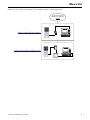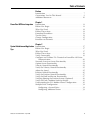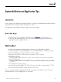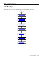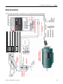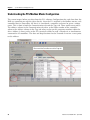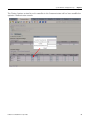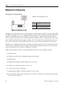
1
Position Control via HMI Connected
Components Building Block
Quick Start
Important User Information
Solid state equipment has operational characteristics differing from those of electromechanical equipment. Safety Guidelines
for the Application, Installation and Maintenance of Solid State Controls (publication SGI-1.1 available from your local
Rockwell Automation sales office or online at http://literature.rockwellautomation.com) describes some important differences
between solid state equipment and hard-wired electromechanical devices. Because of this difference, and also because of the
wide variety of uses for solid state equipment, all persons responsible for applying this equipment must satisfy themselves
that each intended application of this equipment is acceptable.
In no event will Rockwell Automation, Inc. be responsible or liable for indirect or consequential damages resulting from the
use or application of this equipment.
The examples and diagrams in this manual are included solely for illustrative purposes. Because of the many variables and
requirements associated with any particular installation, Rockwell Automation, Inc. cannot assume responsibility or liability
for actual use based on the examples and diagrams.
No patent liability is assumed by Rockwell Automation, Inc. with respect to use of information, circuits, equipment, or
software described in this manual.
Reproduction of the contents of this manual, in whole or in part, without written permission of Rockwell Automation, Inc., is
prohibited.
Throughout this manual, when necessary, we use notes to make you aware of safety considerations.
WARNING
IMPORTANT
Identifies information about practices or circumstances that can cause an explosion in a hazardous environment, which may
lead to personal injury or death, property damage, or economic loss.
Identifies information that is critical for successful application and understanding of the product.
ATTENTION
Identifies information about practices or circumstances that can lead to personal injury or death, property damage, or economic
loss. Attentions help you identify a hazard, avoid a hazard, and recognize the consequence.
SHOCK HAZARD
Labels may be on or inside the equipment, for example, a drive or motor, to alert people that dangerous voltage may be present.
BURN HAZARD
Labels may be on or inside the equipment, for example, a drive or motor, to alert people that surfaces may reach dangerous
temperatures.
Allen-Bradley, MicroLogix, PanelView, PanelView™ Component, PowerFlex, PowerFlex 40P, TechConnect, and Rockwell Automation are trademarks of Rockwell Automation, Inc.
Trademarks not belonging to Rockwell Automation are property of their respective companies.
Where to Start
Follow the path below to complete your Position Control via HMI application.
Connected Components
Building Blocks, publication
CC-QS001
Chapter 1 PowerFlex 40P Drive Integration
A/C+
Chapter 2 System Validation and Application Tips
3Publication CC-QS007B-EN-P - April 2009
3
Where to Start
Notes:
4
Publication CC-QS007B-EN-P - April 2009
Table of Contents
Preface
Introduction . . . . . . . . . . . . . . . . . . . . . . . . . . . . . . . . . . . . 7
Conventions Used in This Manual . . . . . . . . . . . . . . . . . . . . 9
Additional Resources . . . . . . . . . . . . . . . . . . . . . . . . . . . . . . 10
Chapter 1
PowerFlex 40P Drive Integration
Introduction . . . . . . . .
Before You Begin . . . .
What You Need. . . . . .
Follow These Steps . . .
Download Parameters .
Test the Drive . . . . . . .
Change Configuration .
Reconnect to Network .
.
.
.
.
.
.
.
.
.
.
.
.
.
.
.
.
.
.
.
.
.
.
.
.
.
.
.
.
.
.
.
.
.
.
.
.
.
.
.
.
.
.
.
.
.
.
.
.
.
.
.
.
.
.
.
.
.
.
.
.
.
.
.
.
.
.
.
.
.
.
.
.
.
.
.
.
.
.
.
.
.
.
.
.
.
.
.
.
.
.
.
.
.
.
.
.
.
.
.
.
.
.
.
.
.
.
.
.
.
.
.
.
.
.
.
.
.
.
.
.
.
.
.
.
.
.
.
.
.
.
.
.
.
.
.
.
.
.
.
.
.
.
.
.
.
.
.
.
.
.
.
.
.
.
.
.
.
.
.
.
.
.
.
.
.
.
.
.
.
.
.
.
.
.
.
.
.
.
.
.
.
.
.
.
.
.
.
.
.
.
.
.
.
.
.
.
.
.
.
.
.
.
.
.
.
.
.
.
.
.
.
.
.
.
.
.
.
.
.
.
.
.
.
.
11
11
12
12
13
14
15
15
Chapter 2
System Validation and Application Introduction . . . . . . . . . . . . . . . . . . . . . . . . . . . . . . . . . . . . 17
Before You Begin . . . . . . . . . . . . . . . . . . . . . . . . . . . . . . . . 17
Tips
What You Need. . . . . . . . . . . . . . . . . . . . . . . . . . . . . . . . . . 17
Follow These Steps . . . . . . . . . . . . . . . . . . . . . . . . . . . . . . . 18
Verify Connections . . . . . . . . . . . . . . . . . . . . . . . . . . . . . . . 19
Configure and Validate PVc Terminal to PowerFlex 40P Drive
Communication . . . . . . . . . . . . . . . . . . . . . . . . . . . . . . . 20
Network Overview Screen Functionality . . . . . . . . . . . . . . . . 21
Option Screen Functionality . . . . . . . . . . . . . . . . . . . . . . . . . 23
Velocity Control Functionality . . . . . . . . . . . . . . . . . . . . . . . 24
Verify the Velocity Control Functionality. . . . . . . . . . . . . . . . 25
Adjust the Speed . . . . . . . . . . . . . . . . . . . . . . . . . . . . . . . . . 25
Position Control Functionality . . . . . . . . . . . . . . . . . . . . . . . 26
Verify the Position Control Functionality . . . . . . . . . . . . . . . . 27
Verify the Hold and Restart Functionality . . . . . . . . . . . . . . . 27
Verifying Homing the Position System (Optional) . . . . . . . . . 28
Verify the Fault Condition Look-up Display . . . . . . . . . . . . . 29
Understanding the PVc Modbus Master Configuration . . . . . . 30
Multiple Drive Configuration . . . . . . . . . . . . . . . . . . . . . . . . 32
Configuring a Second Drive . . . . . . . . . . . . . . . . . . . . . . 32
Configuring Additional Drives . . . . . . . . . . . . . . . . . . . . 33
Publication CC-QS007B-EN-P - April 2009
5
Table of Contents
Notes:
6
Publication CC-QS007B-EN-P - April 2009
Preface
Introduction
This Position Control via HMI Connected Components Building Block
Quick Start is designed to provide a way to implement a connected
component for position control. Although this may appear similar to
the Position Control Connected Components Building Block Quick
Start, publication CC-QS003, which uses a MicroLogix controller, there
are several differences when connecting directly to the PanelView
Component terminal.
• The PanelView Component (PVc) terminal, not the MicroLogix
controller, becomes the Modbus master.
• Communication setup is done using a 1761-NET-AIC RS232/485
converter from the 2711C600 PanelView to the Powerflex 40P
(PF40P) device.
• Tags are created in the PVc terminal which point directly to
Powerflex 40P addresses within the product.
• Additional devices require a status indicator on every screen to
maintain communication. (See Multiple Drive Configuration on
page 32 for details.)
The drive has many configurable parameters, but only a few have
been modified in this simple positioning building block example. In
fact, it uses the same parameter configuration as the Position Control
Connected Components Building Block Quick Start, which uses a
MicroLogix controller, except that E249 is set to 'Position' and E216 is
set to ‘Quad Check’.
This Quick Start provides you with control of a one- and two-axis
system via the PanelView Component terminal without a MicroLogix
controller. To make this implementation smooth, files for both oneaxis and two-axis control are provided on the Connected Component
Building Blocks Overview CD, publication CC-QR001. Follow the
steps in Chapter 1 and Chapter 2 to complete the one-axis system first.
Then follow the steps in Multiple Drive Configuration on page 32 if
you want to complete a two-axis system. To add additional drives,
you must modify your PanelView Component application.
IMPORTANT
Use this Quick Start in conjunction with the Connected
Components Building Blocks Quick Start, publication CC-QS001.
Refer to Additional Resources on page 10 for a listing of other
related documents.
To assist in the design and installation of your system, application files
and other information are provided on the Connected Component
Building Blocks Overview CD, publication CC-QR001. The CD
provides bills of materials (BOM), CAD drawings for panel layout and
wiring, control programs, Human Machine Interface (HMI) screens,
and more. With these tools and the built-in best-practices design, the
Publication CC-QS007B-EN-P - April 2009
7
Preface
system designer is free to focus on the design of their machine control
and not on design overhead tasks.
The beginning of each chapter contains the following information.
Read these sections carefully before beginning work in each chapter:
• Before You Begin - This section lists the steps that must be
completed and decisions that must be made before starting that
chapter. The chapters in this quick start do not have to be
completed in the order in which they appear, but this section
defines the minimum amount of preparation required before
completing the current chapter.
• What You Need - This section lists the tools that are required to
complete the steps in the current chapter. This includes, but is
not limited to, hardware and software.
• Follow These Steps - This illustrates the steps in the current
chapter and identifies which steps are required to complete the
examples.
8
Publication CC-QS007B-EN-P - April 2009
Preface
Conventions Used in This
Manual
This manual uses the following conventions.
Convention
Meaning
Example
Click
Click the left mouse button once.
Click OK.
Double-click
Click the left mouse button twice in quick succession.
Scroll to 1:0.127 and double-click on it.
Select
Use the mouse to highlight a specific option.
Select Baud 115,000.
Enter
What you type.
Enter the following values.
Press
Press a specific key on the keyboard or the monitor.
Press Forward and then Reverse.
>
This symbol is used to indicate a sub-menu name.
Choose File>Menu>Options.
Publication CC-QS007B-EN-P - April 2009
9
Preface
Additional Resources
Resource
Description
Connected Components Building Blocks Quick Start, Provides information on how to select products and gain access to panel and wiring
publication CC-QS001
information.
Connected Component Building Blocks Overview
CD, publication CC-QR001
Provides files for the Connected Component Building Blocks.
PanelView Component Operator Terminals User
Manual, publication 2711C-UM001
Provides information on using the PanelView Component HMI Terminals.
PowerFlex 40P User Manual, publication 22DUM001
Provides information on installing the PowerFlex 40P Adjustable Frequency AC Drive
including wiring and parameter setup.
1203-USB Converter User Manual DRIVES-UM001
Provides information on communicating between a computer and Allen-Bradley
DPI/DSI/Scanport devices.
AIC+ Advanced Interface Converter User Manual,
publication 1761-UM004
Provides information on using the 1761-NET-AIC.
Bulletin 842 Encoder Accessories, publication 845CA500
Provides descriptions and specifications for accessories for encoders.
Allen-Bradley Control Matched Motor Catalog,
publication RAPS-CA001
Provides information on factors important to the proper selection, use, and service
of motors and their components and accessories.
http://www.ab.com/drives/driveexplorer
Provides access to DriveExplorerLite software.
http://www.ab.com
Provides access to the Allen-Bradley website.
http://www.rockwellautomation.com/
knowledgebase
Provides access to self-service support.
http://www.rockwellautomation.com/components/
connected
Provides access to the Connected Components website.
10
Publication CC-QS007B-EN-P - April 2009
Chapter
1
PowerFlex 40P Drive Integration
Introduction
This chapter explains how to download parameters to and test a PowerFlex 40P drive with
simple-position logic control created in the StepLogic Setup Position Wizard within DriveExplorer
software.
This application example simulates a smart position sequence using an encoder where position,
logic, and dwell time at position depend on the operations being performed on the motor shaft.
Before You Begin
Review the Connected Components Building Blocks Quick Start, publication CC-QS001, assuring
that you have completed hardware design and installation recommendations as well as software
installation.
Publication CC-QS007B-EN-P - April 2009
11
Chapter 1
PowerFlex 40P Drive Integration
What You Need
•
Personal computer with DriveExplorer (Full version) software installed
•
Connected Component Building Blocks Overview CD, publication CC-QR001
•
PowerFlex 40P drive
•
Correct power for your application
•
1203-USB Universal Serial Bus (USB) Converter Module
•
22-HIM-H10 Cable (included with the 1203-USB Converter Module)
PowerFlex 40P configuration for downloading parameters
1203-USB
Converter
Module
USB Cable
PowerFlex 40P Drive
Personal Computer
22-HIM-H10 Cable
Follow These Steps
Follow these steps to download drive parameters to the PVc terminal, test the drive, and change
parameter configuration.
Start
Download Parameters,
page 13
Test the Drive,
page 14
Change Configuration,
page 15
Reconnect to Network,
page 15
12
Publication CC-QS007B-EN-P - April 2009
PowerFlex 40P Drive Integration
Chapter 1
Download Parameters
1. Disconnect the network cable connected to the RJ45 port on the PowerFlex 40P drive.
2. Connect your personal computer to the RJ45 port on the PowerFlex 40P drive using the 1203USB Converter Module.
3. Launch DriveExplorer software.
4. At startup, click OK if prompted.
5. Choose Explore>Configure Communication.
6. Select Serial.
7. Select COM x.
The x represents the name of your USB comm port.
8. Select Baud 115,000.
9. Click OK.
10. Choose Explore>Connect>Serial Point-to-Point.
Once you are connected, this application
window appears.
11. Download the default parameters set from the file provided on the Connected Components
Building Blocks Overview CD, publication CC-QR001.
a. Choose Actions>Download Saved File.
b. If prompted to continue, click Yes.
c. If not already inserted, insert the CD into your personal computer.
d. In the Open window, browse to the Files\Building Blocks Folder\Simple Position Control
Via HMI directory.
Publication CC-QS007B-EN-P - April 2009
13
Chapter 1
PowerFlex 40P Drive Integration
e. Select the ‘HMI to PF40P-Position C0_01.csf’ file and click Open.
This progress window appears.
When the process completes, an application
window opens.
12. In the application window, choose Actions>Control Bar.
13. In the Load Control Bar window, click OK.
Test the Drive
WARNING
Stay clear of the motor shaft.
Failure to observe this safety precaution could result in personal injury or damage to equipment.
The motor ramps up to 45 Hz and back down to 0 Hz before stopping.
1. Click Start.
2. Check the drive for any fault condition.
•
If after five seconds, the drive does not fault, click Stop. Skip to Change Configuration.
•
If F091 flashes on the drive denoting Encoder Loss, perform the following steps.
a. Verify all encoder connections are secure or swap channel inputs since Parameter 1:0.216
is configured for ‘Quad Check’.
b. Choose Explore>Device Properties.
c. Click the Faults tab.
d. Select Clear Faults.
e. Click Yes.
f. Click Close.
3. Repeat steps 1 and 2 until the encoder fault is resolved.
14
Publication CC-QS007B-EN-P - April 2009
PowerFlex 40P Drive Integration
Chapter 1
Change Configuration
1. In the left column, select Parameter List.
2. Click in the white space in the right column, but do not click on any parameter.
3. Scroll to 1:0.127 and double-click on it.
4. In the 127 - Autotune window, in the Value drop-down list, select Rotate Tune.
5. Click OK.
6. Choose Actions>Control Bar.
7. On the Control Bar, click Start.
8. After the Autotune function has completed, verify that the Value for parameter 1:0.127
Autotune has returned to Ready/Idle.
9. (Optional) Save all the configuration changes to your personal computer for future reference.
a. Choose Actions>Upload and Save.
b. Select All Parameters.
c. Click OK.
d. Wait for the uploading process to complete.
e. Specify the name and location for the saved file.
f. Click Save.
Reconnect to Network
1. Disconnect the 1203-USB Converter Module from the PowerFlex 40P drive.
2. Reconnect the network cable, which was disconnected in Download Parameters, to the RJ45
port on the PowerFlex 40P drive.
3. Cycle power to the drive to accept the new node address in the parameter file that was
downloaded.
Publication CC-QS007B-EN-P - April 2009
15
Chapter 1
PowerFlex 40P Drive Integration
Additional Resources
Refer to page 10 for a listing of product and information resources.
16
Publication CC-QS007B-EN-P - April 2009
Chapter
2
System Validation and Application Tips
Introduction
In this chapter, you validate that communication is occurring as intended between the PanelView
Component (PVc) terminal and the PowerFlex 40P drive.
The operation of the Position Control sample screens is described.
Before You Begin
• Verify that you have completed all of the steps in Chapter 1 of this document.
• Verify that the PowerFlex drive, NET AIC, and PanelView Component terminal have
appropriate power applied to them.
What You Need
•
•
•
•
•
•
•
•
•
Connected Component Building Blocks Overview CD, publication CC-QR001.
Personal computer with Internet Explorer 7.x or Mozilla Firefox 2.x software installed.
PVc TC600 terminal, catalog number 2711C-T6C or higher.
Ethernet CAT5 cable to connect personal computer to PVc terminal.
PowerFlex 40P drive.
(Catalog number 22D-D1P4N104 is used in this document, but your drive may differ.)
Motor with Encoder.
(Catalog number CM201-NV00118AXZCA-334 is used in this document, but your motor
may differ.)
1761-NET-AIC networking device.
Serial Cable, catalog number 1761-CBL-AC00, or serial cable, catalog number 1747-CP3.
Pre-Wired Cable Assembly, catalog number 845-CA-C-xx.
This is a complete Modbus configuration. The PVc terminal is the Modbus master. No other
network protocol can be configured at the same time.
17Publication CC-QS007B-EN-P - April 2009
17
Chapter 2
System Validation and Application Tips
Follow These Steps
Follow these steps to verify that communication is occurring between your devices.
Start
Verify Connections, page 19
Configure and Validate PVc
Terminal to PowerFlex 40P
Drive Communication, page 20
Verify the Velocity Control
Functionality, page 25
Adjust the Speed, page 25
Verify the Position Control
Functionality, page 27
Verify the Hold and Restart
Functionality, page 27
Verify the Fault Condition
Look-up Display, page 29
18
Publication CC-QS007B-EN-P - April 2009
Publication CC-QS007B-EN-P - April 2009
Earth Ground
to Ground Bus
dc- Functional
1761-CBL-AC00
or 1747-CP3
Serial Cable
dc+
DIP switch selects 12 or 5 volt power supplied at
terminals “+V” and “Cm” for the encoder.
Single channel, pulse train, or quadrature A input
Quadrature B input
Internal power source 250 mA (isolated)
Description
10-pin Pre-Wired Cable Assembly
845-CA-C-xx
120 ohm
1/4 Watt
Resistor
AK-U0-RJ45-TB2P
PowerFlex 40P 22D-D1P4N104
(1) When using 12V Encoder power, 24V I/O power, maximum output current at
I/O Terminal 11 is 60 mA.
Output (1)
Motor with Encoder
CM201-NV00118AXZCA-334
1761-NET-AIC
PVc Terminal
2711C-T6C
Encoder A (NOT)
Encoder A
AA
Encoder B (NOT)
Encoder B
B
Power Return
Cm
B-
5V-12V Power(1)
+V
No. Signal
System Validation and Application Tips
Chapter 2
Verify Connections
Confirm that your primary components are connected as illustrated below.
19
Chapter 2
System Validation and Application Tips
Configure and Validate PVc Terminal to PowerFlex 40P Drive Communication
The following Position Point-to-Point Control program example is provided and configured for
communicating with one drive, set to node address 1. The step-by-step procedures are listed for
one drive using the single drive program example.
If your application has multiple drives, you should perform the same steps for each subsequent
drive. Refer to Multiple Drive Configuration, page 32.
Follow the steps in the next sections to verify or change the settings.
This 6-inch color touchscreen PanelView Component (PVc) terminal communicates with the
PowerFlex 40P drive via the 1761-NET-AIC RS232 to 485 network. The PVc application reads from
and writes to the address of the PowerFlex 40P drive directly via tags created in the PVc
application.
1. On the personal computer, choose Start>Settings>Network Connections>Local Area
Connection>Properties>Internet Protocol (TCP/IP)>Properties>Use the following IP address.
2. Enter the following values.
• IP address: 192.168.1.1
• Subnet mask: 255.255.255.0
3. Click OK.
4. Close all windows opened in this process.
5. Refer to Connected Component Building Blocks Quick Start, publication CC-QS001.
a. Follow the procedures in the Set Up the PanelView Component Operator Interface
Terminal section of Chapter 3.
b. Follow the procedures in Load Your HMI Screens section of Chapter 3. When directed to
browse to the .cha file on the CD, browse to Files\Building Blocks Folder\Simple
Position Control Via HMI\HMI to 1 PF40P-Position C0_01.cha.
Disregard instructions for MicroLogix controller, as that is not a component in this
procedure.
c. After the application is finished loading, disconnect the Ethernet cable from the PVc
terminal.
You may eject the Connected Component Building Blocks Quick Start CD now.
20
Publication CC-QS007B-EN-P - April 2009
System Validation and Application Tips
Chapter 2
Network Overview Screen Functionality
This Network Overview screen has been preconfigured to support one drive, node address 1.
Once the PVc application is running, verify that the Network Overview screen indicates the drive
is enabled by displaying Ready, as shown below.
Ready Status indicators
showing drive enabled
and stopped
The object on the left side of the screen is a status indicator. This provides the state of the drive
via the Logic Status word. Within the object for this indicator is a second status indicator used to
display if the drive is running or stopped. So the following combinations can occur:
• Ready - Running or Stopped
• Not Ready - Stopped
• Faulted
TIP
For diagnostic information on faults, refer to step 2 in Verify the Fault Condition Look-up
Display, page 29, for information on how to identify Fault Type, Description, and
Actions.
Any objects in the center of the screen above the Start and Stop buttons are GoTo buttons which
take you to additional functions for that axis.
The object on the right side of the screen displays the commanded mode: Position or Velocity.
Publication CC-QS007B-EN-P - April 2009
21
Chapter 2
System Validation and Application Tips
If communication is broken when the PVc application is running, the Ready status indicator
objects will be replaced by X marks and there will be a yellow banner message similar to the
illustration below. This indicates the PVc application is not able to communicate with the network
at the configured Modbus address. To correct this communication error, resolve the wiring
connection issue. When you re-establish communication, the Ready status objects return to
normal status. Then press OK on all instances of the banner until they are all closed.
Error
Banner
Communication
Broken
TIP
During a communication loss, the drive’s fault code F081 [Comm Loss] will never appear on the
screen above and neither will the CLR Fault object button. The PVc terminal can only read from a
connected device. If communication is lost, the read function is lost. When communication is
reestablished, the fault is cleared automatically.
This is a three-wire control function. Pressing the Start button enables all drives connected and in
a ready state to start at once. Pressing the Stop button stops all drives and also clears applicable
faults.
You can execute a broadcast Start and Stop from the Network Overview screen also.
TIP
Before starting, verify which mode and associated position your drive is in, to make sure it is safe.
The
button in the top-right corner of the Network Overview screen lets you enter the PVc
File Manager screen. Your application will continue to run. To re-enter the Network Overview
screen, press Run on the File Manager screen.
IMPORTANT
22
We recommend that the broadcast Stop be issued before proceeding with any deliberate action to
enter the File Manager screen. To eliminate the option to enter the File Manager screen, you can
remove the X button GoTo object from the Network Overview screen in your final application.
Publication CC-QS007B-EN-P - April 2009
System Validation and Application Tips
Chapter 2
Option Screen Functionality
When that the PVc terminal is successfully communicating with the PowerFlex 40P drive, you will
use the procedures in Follow These Steps, page 18 to test the Control functionality.
To access the Control functionality, press the Axis #1 button on the Network Overview screen.
On this screen, the header is Axis #1 Option
Screen, a text object. You can change the text
for this object to reflect an appropriate name
and description for your system.
Below the header text object is a status of the
commanded mode. It is the same status found
on the Network Overview screen. To access
the logic functions in either of the two modes,
press Go to Velocity screen or Go to Position
screen button. Each will take you to its
respective functional control screen.
Caution
message
Change mode
button
Upon entering this screen, you may notice a flashing caution message displayed on the lower
portion of the screen. This only appears if the drive is active. Because of the design of the PVc
terminal, all buttons for both Position and Velocity functions are visible and available at all times
on this screen. At any time, it is possible to change the mode (Position or Velocity), but doing so
while the motor is running is not recommended. The caution message is provided to notify you
to prevent unwanted changes to your process. This screen is the only place where this caution is
needed because this screen is the only one with the capability to change the mode.
Pressing the
button in the top-right corner of the Axis #1 Option Screen takes you back to
the previous screen.
A Stop button has been provided on every screen. However,
unlike the Network Overview screen which sends a broadcast
Stop, all other Stop buttons are specific to the active Axis
screen.
Publication CC-QS007B-EN-P - April 2009
23
Chapter 2
System Validation and Application Tips
Velocity Control Functionality
The second heading on this screen indicates which
Commanded Mode is enabled. (If it displays Position, exit
the screen by using the X button and change the mode in
the Option Screen.)
Entering the Velocity functional control screen allows these
functions shown on the right side of the screen:
• Standard three-wire Start/Stop control of the drive
• Forward or Reverse directions
• Jog function (default of 10 Hz)
This screen also displays the current status of that specific drive as follows.
The numeric displays in the middle show:
•
•
•
•
the
the
the
the
output current in Amps (I load x100).
output voltage in Volts (V out x10).
reference frequency in Hertz (Hz Ref x100).
actual frequency in Hertz (Hz Act x100).
The drive provides these values to the PVc terminal as integer values, so the text ‘x100’ and
‘x10’ are shown to help clarify the value. (So, for example, 6000 Hz is actually 60.00 Hz.)
The Hz Ref display is also a numeric entry button. Refer to Adjust the Speed, page 25. When
you press this button, a numeric keypad is displayed to let you enter a new reference
frequency. This value is an integer. So, for example, entering 3520 is actually 35.20 Hz to the
drive. Only the Velocity screen has this numeric keypad function.
The indicators on the left side show:
•
•
•
•
24
whether the drive is Ready to run (not faulted).
Active (running).
the direction (Forward or Reverse).
whether the drive is running at the reference frequency (At Ref).
Publication CC-QS007B-EN-P - April 2009
System Validation and Application Tips
Chapter 2
Verify the Velocity Control Functionality
Follow this procedure to test the velocity control.
1. Press Forward and then Reverse. Using the built-in display, verify that the drive is switching
between these two states as indicated by a green status indicator. The text object identifies
the actual state. If the drive is not switching between forward and reverse, go back to Verify
Connections on page 19 and Configure and Validate PVc Terminal to PowerFlex 40P Drive
Communication on page 20 to verify there is communication to this drive.
2. With the motor disconnected from the load (open shaft), test the jog function by pressing
and holding Jog. The drive will ramp up to the 10 Hz (default) Jog frequency.
3. Release Jog. The drive should decelerate back to stop.
4. Press Start. The drive should accelerate up to the reference frequency displayed in Hz Ref.
5. Press the reference frequency button (Hz Ref) and enter a new reference frequency. The
drive accepts the new reference frequency and the Hz Ref value updates to the new value.
Adjust the Speed
Follow this procedure to adjust the relative speed of your positioning system while in Velocity
mode.
1. Press the reference frequency
button (Hz Ref) button.
The numeric keypad appears.
Example: 03520
means 35.20 Hz.
2. Type the new raw speed value.
3. Press Enter.
The keypad closes and the motor
speed is updated with the new
value.
TIP
Enter
Press ESC to exit at any time.
Publication CC-QS007B-EN-P - April 2009
25
Chapter 2
System Validation and Application Tips
Position Control Functionality
The second heading on this screen indicates which
Commanded Mode is enabled. (If it displays Velocity, exit
the screen by pressing the X button and change the mode
in the Option screen to Position.)
Entering the Position functional control screen allows these
functions shown on the right side of the screen:
• Standard three-wire Start/Stop control of the drive
• Hold (causes the drive to remain at its current step)
• Position Redefine (resets the home position to the
current position)
• Home (when set, the next Start command causes the drive to find home)
• Enable Logic 1 and Logic 2 (cause the drive to jump to a predefined step)
This screen also displays the current status of that specific drive as follows.
The indicators on the left side show:
•
•
•
•
•
Pos Step # (active value in the StepLogic sequence).
At Position (last completed step number).
At Home (indicates when a new home position has been set).
Homed (indicates when a new or existing home position has been reached).
Ready (not faulted).
The numeric displays in the middle show:
• output current in Amps (I load x100).
• output voltage in Volts (V out x10).
• actual frequency in Hertz (Hz Act x100).
The drive provides these values to the PVc terminal as integer values, so the text ‘x100’ and
‘x10’ are shown to help clarify the values. (So, for example, 3000 Hz is actually 30.00 Hz.)
26
Publication CC-QS007B-EN-P - April 2009
System Validation and Application Tips
Chapter 2
Verify the Position Control Functionality
Follow this procedure to start your Position Control example using PowerFlex 40P.csf
downloaded to the drive.
1. On the Options screen, the drive must be set to
Position mode. If it is in Velocity mode, press
Press to Enable Position Mode.
2. Press Go to Position screen.
3. Press Pos Redfn.
This marks the new starting point.
4. Press Start.
The drive will step through states 0...5 and repeat.
5. Press Lgc1 Enable at any point in the sequence.
The Pos Step # jumps to step 6.
6. Press Lgc2 Enable within five seconds of pressing Lgc1 Enable. The drive jumps to step 7
(end sequence) and the drive stops and resets to step 0.
If you do not press Lgc2 Enable within five seconds of pressing Lgc1 Enable, the drive goes
to step 0 and repeats.
Verify the Hold and Restart Functionality
Follow this procedure to hold (pause) your position system and then resume the system.
1. Press Start.
2. Press HOLD.
The button displays ‘HOLDING’ while flashing. This is a maintain function button.
3. Press HOLDING.
The drive releases the hold bit and resumes to the next step.
Publication CC-QS007B-EN-P - April 2009
27
Chapter 2
System Validation and Application Tips
4. Press Stop.
The motor stops.
Verifying Homing the Position System (Optional)
Follow this procedure if you want to home your position system by using a sensor wired into the
drive digital input.
1. Press HOME with the drive stopped.
The HOME button displays Homing while flashing. This is a maintain function button.
2. Press Start.
The motor rotates at 10 Hz looking for the home location. Once the object has reached the
sensor, the At Home indicator turns green.
The Homed indicator changes state to green unless the system has been previously Homed.
3. Press Homing to release the Home function.
4. Press Start.
The Pos Step # now displays 0 and the system begins stepping through the sequence.
5. Verify that values for ‘I load x100’, ‘V out x10’, and ‘Hz Act x100’ are displayed while
running.
28
Publication CC-QS007B-EN-P - April 2009
System Validation and Application Tips
Chapter 2
Verify the Fault Condition Look-up Display
Follow this procedure to verify the active fault status feature of the control screen. The Fault
Look-up display lets you cross-reference a drive’s active fault.
1. Disconnect the incoming power to the drive until
the F4 fault appears and then quickly restore the
incoming power. (If the drive powers down
completely, the fault resets.)
2. On the current display, press the fault indicator
button, F4 Under Voltage in this case. It will be
blinking with the indicated fault name and code
number.
The text on this fault indicator button is specific to each individual fault. Pressing this button
takes you to the Fault Type, Description and Action display for that fault.
The Fault Type, Description & Action display appears.
The screen provides the same information and
troubleshooting tips for the PowerFlex 40P drive as
found in the drive user documentation.
3. Press X to return to the previous screen.
Upon return to the previous screen, notice that the fault is still active.
4. Press
to clear the fault. The fault clears, as indicated by the fault display button
disappearing, along with the CLR Fault button.
Publication CC-QS007B-EN-P - April 2009
29
Chapter 2
System Validation and Application Tips
Understanding the PVc Modbus Master Configuration
The screen images below are taken from the PVc software Configuration tabs and show how the
HMI can communicate with the drive directly. Since the PVc terminal is the Modbus master, each
controlled device (PowerFlex 40P drive) is considered a controller and must be given a unique
name. This is done in both the Communication tab and the Tags tab. These names must match.
The address column in the Communication tab refers to the Node number of the controller
whereas the address column in the Tags tab refers to the specific parameter number within the
drive. Address 0 always refers to the PVc terminal’s ability to send a 'Broadcast' or simultaneous
command to all controllers. The Start and Stop functions on the Network Overview screen point
to this address.
Must match the Controller name in the Tags tab.
30
Publication CC-QS007B-EN-P - April 2009
System Validation and Application Tips
Chapter 2
The Timing Options section for each controller in the Communication tab has been modified to
optimize communication transfer.
Publication CC-QS007B-EN-P - April 2009
31
Chapter 2
System Validation and Application Tips
Multiple Drive Configuration
Configuring a Second Drive
Example for illustration purposes only
Item
Description
1
Axis 1
2
Axis 2 (with terminating resistor)
Multiple drive configuration uses a second Position Control routine example. This example (HMI
to 2 PF40Ps-Position C0_01.cha) supports Modbus communication with two PowerFlex 40P drives
without any modifications. Since a Modbus network supports communication with only one
device at a time, the more drives on the network, the longer it takes to communicate with all the
drives. With the default communication settings, the PVc terminal takes approximately 40 ms to
get a status update from each enabled drive because two separate read requests are required.
Multiple drive configuration includes a Broadcast Start/Stop function. On the Network Overview
screen, there are buttons for Start and Stop. These buttons simultaneously start or stop all drives
on the network that are connected, configured, and ready.
Follow this procedure to add a second PowerFlex 40P drive to your Modbus network.
1. Remove power.
2. Install the second drive, including wiring to the encoder.
3. Apply power.
4. Download the ‘HMI to PF40P-Position C0_01.csf’ file.
5. Change the value of parameter 1:0.104 to 2.
6. Cycle power to the second drive.
7. Download the ‘HMI to 2 PF40Ps-Position C0_01.cha’ file.
8. Daisy-chain the RJ45 connector from drive 1 to drive 2, making sure to move the termination
resistor to the end drive.
32
Publication CC-QS007B-EN-P - April 2009
System Validation and Application Tips
Chapter 2
9. On the Network Overview screen, verify that the status indicators on the left side indicate
the drive is ready.
If the drive is not ready, resolve any faults or communication errors.
10. Test the newly-configured network by pressing the Start and Stop broadcast buttons to
command simultaneous Start/Stop to all drives on the network.
11. Test the second drive by performing all the test functions in preceding sections of this
chapter.
Configuring Additional Drives
Application Changes
To add additional drives, you must modify your PanelView Component application as
appropriate for your system needs. Except for understanding the drive status indicator, described
below, application changes are beyond the scope of this Quick Start.
Drive Status Indicator
To maintain communication between the PVc terminal and the drives, a
status indicator for additional drives is needed on every screen. Without this,
communication will be lost to all non-active-screen related drives. In the
application code provided for two-axis configuration, this is a transparent
drive object located in the lower right corner. For two-axis configuration, the
drive object on Axis 1-related screens points to the Ready bit in the drive
status word for Axis 2. Likewise, the drive object on Axis 2-related screens
points to the Ready bit in the drive status word for Axis 1.
As you add more drives, one of these objects is needed on every screen pointing to one of each
other axis. So for a three-axis configuration, two drive objects are needed on Axis 1-related
screens to point to the Ready bit in the drive status word for Axis 2 and Axis 3 respectively.
Similarly, the two drive objects on Axis 2-related screens must point to the Ready bit in the drive
status word for Axis 1 and Axis 3 respectively.
If you choose, you can make these drive status indicator objects visible.
Publication CC-QS007B-EN-P - April 2009
33
Chapter 2
System Validation and Application Tips
Additional Resources
For detailed steps for various configurations, refer to CCBB Simple Positioning Examples PF40P
StepLogic setup document, which uses DriveExplorer software, located on the Connected
Components Building Blocks Overview CD, publication CC-QR001, in the Building Blocks Folder
for Simple Position.
Refer to page 10 for a listing of product and information resources.
34
Publication CC-QS007B-EN-P - April 2009
Rockwell Automation
Support
Rockwell Automation provides technical information on the Web to assist
you in using its products. At http://support.rockwellautomation.com, you can
find technical manuals, a knowledge base of FAQs, technical and application
notes, sample code and links to software service packs, and a MySupport
feature that you can customize to make the best use of these tools.
For an additional level of technical phone support for installation,
configuration, and troubleshooting, we offer TechConnect Support programs.
For more information, contact your local distributor or Rockwell Automation
representative, or visit http://support.rockwellautomation.com.
Installation Assistance
If you experience a problem with a hardware module within the first 24
hours of installation, please review the information that's contained in this
manual. You can also contact a special Customer Support number for initial
help in getting your module up and running.
United States
1.440.646.3434
Monday – Friday, 8 a.m. – 5 p.m. EST
Outside United
States
Please contact your local Rockwell Automation representative for any
technical support issues.
New Product Satisfaction Return
Rockwell tests all of its products to ensure that they are fully operational
when shipped from the manufacturing facility. However, if your product is
not functioning, it may need to be returned.
United States
Contact your distributor. You must provide a Customer Support case
number (see phone number above to obtain one) to your distributor in
order to complete the return process.
Outside United
States
Please contact your local Rockwell Automation representative for
return procedure.
Publication CC-QS007B-EN-P - April 2009
Supersedes Publication CC-QS007A-EN-P - January 2009
Copyright © 2009 Rockwell Automation, Inc. All rights reserved. Printed in the U.S.A.